EP2018995A1 - Steuervorrichtung für elektroauto - Google Patents
Steuervorrichtung für elektroauto Download PDFInfo
- Publication number
- EP2018995A1 EP2018995A1 EP06732581A EP06732581A EP2018995A1 EP 2018995 A1 EP2018995 A1 EP 2018995A1 EP 06732581 A EP06732581 A EP 06732581A EP 06732581 A EP06732581 A EP 06732581A EP 2018995 A1 EP2018995 A1 EP 2018995A1
- Authority
- EP
- European Patent Office
- Prior art keywords
- load
- inverter
- state
- electric
- power
- Prior art date
- Legal status (The legal status is an assumption and is not a legal conclusion. Google has not performed a legal analysis and makes no representation as to the accuracy of the status listed.)
- Withdrawn
Links
Images


Classifications
-
- B—PERFORMING OPERATIONS; TRANSPORTING
- B60—VEHICLES IN GENERAL
- B60L—PROPULSION OF ELECTRICALLY-PROPELLED VEHICLES; SUPPLYING ELECTRIC POWER FOR AUXILIARY EQUIPMENT OF ELECTRICALLY-PROPELLED VEHICLES; ELECTRODYNAMIC BRAKE SYSTEMS FOR VEHICLES IN GENERAL; MAGNETIC SUSPENSION OR LEVITATION FOR VEHICLES; MONITORING OPERATING VARIABLES OF ELECTRICALLY-PROPELLED VEHICLES; ELECTRIC SAFETY DEVICES FOR ELECTRICALLY-PROPELLED VEHICLES
- B60L7/00—Electrodynamic brake systems for vehicles in general
- B60L7/10—Dynamic electric regenerative braking
- B60L7/14—Dynamic electric regenerative braking for vehicles propelled by AC motors
-
- B—PERFORMING OPERATIONS; TRANSPORTING
- B60—VEHICLES IN GENERAL
- B60L—PROPULSION OF ELECTRICALLY-PROPELLED VEHICLES; SUPPLYING ELECTRIC POWER FOR AUXILIARY EQUIPMENT OF ELECTRICALLY-PROPELLED VEHICLES; ELECTRODYNAMIC BRAKE SYSTEMS FOR VEHICLES IN GENERAL; MAGNETIC SUSPENSION OR LEVITATION FOR VEHICLES; MONITORING OPERATING VARIABLES OF ELECTRICALLY-PROPELLED VEHICLES; ELECTRIC SAFETY DEVICES FOR ELECTRICALLY-PROPELLED VEHICLES
- B60L9/00—Electric propulsion with power supply external to the vehicle
- B60L9/16—Electric propulsion with power supply external to the vehicle using AC induction motors
- B60L9/18—Electric propulsion with power supply external to the vehicle using AC induction motors fed from DC supply lines
- B60L9/22—Electric propulsion with power supply external to the vehicle using AC induction motors fed from DC supply lines polyphase motors
-
- H—ELECTRICITY
- H02—GENERATION; CONVERSION OR DISTRIBUTION OF ELECTRIC POWER
- H02P—CONTROL OR REGULATION OF ELECTRIC MOTORS, ELECTRIC GENERATORS OR DYNAMO-ELECTRIC CONVERTERS; CONTROLLING TRANSFORMERS, REACTORS OR CHOKE COILS
- H02P29/00—Arrangements for regulating or controlling electric motors, appropriate for both AC and DC motors
- H02P29/02—Providing protection against overload without automatic interruption of supply
- H02P29/024—Detecting a fault condition, e.g. short circuit, locked rotor, open circuit or loss of load
- H02P29/0241—Detecting a fault condition, e.g. short circuit, locked rotor, open circuit or loss of load the fault being an overvoltage
-
- H—ELECTRICITY
- H02—GENERATION; CONVERSION OR DISTRIBUTION OF ELECTRIC POWER
- H02P—CONTROL OR REGULATION OF ELECTRIC MOTORS, ELECTRIC GENERATORS OR DYNAMO-ELECTRIC CONVERTERS; CONTROLLING TRANSFORMERS, REACTORS OR CHOKE COILS
- H02P3/00—Arrangements for stopping or slowing electric motors, generators, or dynamo-electric converters
- H02P3/06—Arrangements for stopping or slowing electric motors, generators, or dynamo-electric converters for stopping or slowing an individual dynamo-electric motor or dynamo-electric converter
- H02P3/18—Arrangements for stopping or slowing electric motors, generators, or dynamo-electric converters for stopping or slowing an individual dynamo-electric motor or dynamo-electric converter for stopping or slowing an AC motor
-
- B—PERFORMING OPERATIONS; TRANSPORTING
- B60—VEHICLES IN GENERAL
- B60L—PROPULSION OF ELECTRICALLY-PROPELLED VEHICLES; SUPPLYING ELECTRIC POWER FOR AUXILIARY EQUIPMENT OF ELECTRICALLY-PROPELLED VEHICLES; ELECTRODYNAMIC BRAKE SYSTEMS FOR VEHICLES IN GENERAL; MAGNETIC SUSPENSION OR LEVITATION FOR VEHICLES; MONITORING OPERATING VARIABLES OF ELECTRICALLY-PROPELLED VEHICLES; ELECTRIC SAFETY DEVICES FOR ELECTRICALLY-PROPELLED VEHICLES
- B60L2200/00—Type of vehicles
- B60L2200/26—Rail vehicles
-
- B—PERFORMING OPERATIONS; TRANSPORTING
- B60—VEHICLES IN GENERAL
- B60L—PROPULSION OF ELECTRICALLY-PROPELLED VEHICLES; SUPPLYING ELECTRIC POWER FOR AUXILIARY EQUIPMENT OF ELECTRICALLY-PROPELLED VEHICLES; ELECTRODYNAMIC BRAKE SYSTEMS FOR VEHICLES IN GENERAL; MAGNETIC SUSPENSION OR LEVITATION FOR VEHICLES; MONITORING OPERATING VARIABLES OF ELECTRICALLY-PROPELLED VEHICLES; ELECTRIC SAFETY DEVICES FOR ELECTRICALLY-PROPELLED VEHICLES
- B60L2210/00—Converter types
- B60L2210/20—AC to AC converters
-
- Y—GENERAL TAGGING OF NEW TECHNOLOGICAL DEVELOPMENTS; GENERAL TAGGING OF CROSS-SECTIONAL TECHNOLOGIES SPANNING OVER SEVERAL SECTIONS OF THE IPC; TECHNICAL SUBJECTS COVERED BY FORMER USPC CROSS-REFERENCE ART COLLECTIONS [XRACs] AND DIGESTS
- Y02—TECHNOLOGIES OR APPLICATIONS FOR MITIGATION OR ADAPTATION AGAINST CLIMATE CHANGE
- Y02T—CLIMATE CHANGE MITIGATION TECHNOLOGIES RELATED TO TRANSPORTATION
- Y02T10/00—Road transport of goods or passengers
- Y02T10/60—Other road transportation technologies with climate change mitigation effect
- Y02T10/72—Electric energy management in electromobility
Definitions
- This invention relates to a control apparatus for an electric train, wherein an AC electric motor is used as a drive source, and the AC electric motor is controlled by a variable-voltage variable-frequency inverter.
- the regenerative energy of the electric train in the regenerative braking state is greater than power which is consumed by the electric train in the power running state
- the voltage of the overhead line or the voltage of a filter capacitor disposed at a stage preceding an inverter increases to an overvoltage, and a protective function is sometimes actuated.
- the regenerative power from the electric train in the regenerative braking state is fined to lower a braking force based on the regenerative braking, and that the lowered component of the braking force is compensated by mechanical braking.
- a brake shoe wears off due to the mechanical braking, and hence, the maintenance of the brake shoe needs to be performed in a certain fixed period.
- a brake chopper which consists of a switching element and a resistor is disposed on the DC side of the inverter.
- the brake chopper is operated to consume the regenerative power. Since, however, the brake chopper is added to a control apparatus in this case, there has been the problem that the control apparatus becomes large in size and high in fabrication cost.
- Fig. 1 of JP2003-199204A Patent Document 1
- an electric-double-layer capacitor which can store regenerative energy is employed instead of the brake chopper.
- the electric-double-layer capacitor in a control apparatus for an electric train, wherein a smoothing capacitor is disposed in a DC power feed circuit which is connected to a DC power feed line through a collector shoe and wherein a DC voltage smoothed by the smoothing capacitor is fed to a variable-voltage variable-frequency inverter, the electric-double-layer capacitor is connected in parallel with the smoothing capacitor through a DC/DC converter having a switching element, and in a regenerative braking state, regenerative energy from the inverter is stored in the electric-double-layer capacitor, whereas in a power running state or a coasting running state, the energy stored in the electric-double-layer capacitor is fed to the power feed line or the inverter.
- Fig. 10 of JP2004-104976A Patent Document 2
- an electric-double-layer capacitor is employed instead of a brake chopper circuit for the purpose of storing regenerative energy.
- This invention has been made in order to solve the above problem, and it has for its object to propose an improved control apparatus for an electric train as can consume surplus regenerative energy by utilizing the load of an auxiliary power source device, without adding the brake chopper or the electric-double-layer capacitor.
- a control apparatus for an electric train is configured including an AC electric motor which drives the electric train, and a variable-voltage variable-frequency inverter which controls the AC electric motor, wherein the variable-voltage variable-frequency inverter has DC side terminals which are connected to a DC power feed circuit of the electric train, and AC side terminals which are connected to the AC electric motor, and wherein, in a power running state of the electric train, the variable-voltage variable-frequency inverter converts DC electric power fed from the DC power feed circuit to the DC side terminals, into AC electric power, so as to feed the AC electric power from the AC side terminals to the AC electric motor, while in a regenerative braking state of the electric train, it converts AC electric power fed from the AC electric motor to the AC side terminals, into DC electric power, so as to feed the DC electric power from the DC side terminals to the DC power feed circuit.
- the control apparatus further includes an auxiliary power source device connected to the DC power feed circuit and load control means for controlling a load connected to the auxiliary power source device, wherein the load control means receives an inverter state signal representative of an operation state of the variable-voltage variable-frequency inverter from it, and the control means controls the load in accordance with the inverter state signal.
- a control apparatus for an electric train is configured including an AC electric motor which drives the electric train, and a variable-voltage variable-frequency inverter which controls the AC electric motor, wherein the variable-voltage variable-frequency inverter has DC side terminals which are connected to a DC power feed circuit of the electric train, and AC side terminals which are connected to the AC electric motor, and wherein, in a power running state of the electric train, the variable-voltage variable-frequency inverter converts DC electric power fed from the DC power feed circuit to the DC side terminals, into AC electric power, so as to feed the AC electric power from the AC side terminals to the AC electric motor, while in a regenerative braking state of the electric train, it converts AC electric power fed from the AC electric motor to the AC side terminals, into DC electric power, so as to feed the DC electric power from the DC side terminals to the DC power feed circuit.
- the control apparatus further includes an auxiliary power source device connected to the DC power feed circuit, load control means for controlling a load connected to the auxiliary power source device, and detection means for detecting DC power feed information representative of a DC power feed state of the DC power feed circuit, wherein the load control means controls the load in accordance with the DC power feed information.
- the load control means receives the inverter state signal representative of the operation state of the variable-voltage variable-frequency inverter from it, and the control means controls the load connected to the auxiliary power source device, in accordance with the inverter state signal, so that the regenerative energy of the DC power feed circuit can be consumed by the load of the auxiliary power source device without disposing a brake chopper or an electric-double-layer capacitor in the DC power feed circuit.
- the load control means receives the DC power feed information of the DC power feed circuit, and it controls the load connected to the auxiliary power source device, in accordance with the DC power feed information, so that the regenerative energy of the DC power feed circuit can be consumed by the load of the auxiliary power source device without disposing a brake chopper or an electric-double-layer capacitor in the DC power feed circuit.
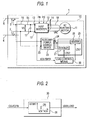
- Fig. 1 is a block diagram showing Embodiment 1 of a control apparatus for an electric train according to this invention.
- the control apparatus 10 for the electric train in Embodiment 1 is the control apparatus installed in the electric train 1.
- the electric train 1 includes a wheel 2, and a collector shoe 3.
- the wheel 2 runs on a track 4, and the collector shoe 3 touches an overhead line, that is, a DC power feed line 5 and receives the feed of DC electric power from the DC power feed line 5.
- the DC power feed line 5 feeds DC electric power to a plurality of electric trains including the electric train 1.
- the prescribed voltage VD0 of the DC power feed line 5 is set at, for example, 1500 (V) or 750 (V).
- the control apparatus 10 includes an AC electric motor 11, an inverter 12, a DC power feed circuit 15, an AC power feed circuit 18, an auxiliary power source device 22, a load 25, and load control means 30.
- the AC electric motor 11 is the drive source of the electric train 1, and it drives the wheel 2.
- This AC electric motor 11 is an AC induction motor of, for example, three phases.
- the inverter 12 is a variable-voltage variable-frequency inverter (VVVF inverter), and it is configured by employing, for example, a thyristor.
- VVVF inverter variable-voltage variable-frequency inverter
- This inverter 12 has a pair of DC side terminals 13, and three-phase AC side terminals 14.
- the DC side terminals 13 are connected to the DC power feed circuit 15.
- the DC voltage of the DC power feed circuit 15 is let be "VD”.
- the AC side terminals 14 are connected to the AC electric motor 11 through the AC power feed circuit 18.
- the AC power feed circuit 18 is a three-phase AC power feed circuit.
- VAC three-phase AC voltage of the AC power feed circuit 18
- the DC power feed circuit 15 includes a reactor 16 and a smoothing capacitor 17, and it connects the DC side terminals 13 of the inverter 12 with the collector shoe 3 and the wheel 2.
- One end of the reactor 16 is connected to the collector shoe 3, while the other end thereof is connected to the plus side terminal of the DC side terminals 13 of the inverter 12.
- the minus side terminal of the DC side terminals 13 is directly connected to the wheel 2, and it is earthed through the wheel 2 as well as the track 4.
- One end of the smoothing capacitor 17 is connected between the reactor 16 and the plus side terminal of the DC side terminals 13, while the other end thereof is connected to the minus side terminal of the DC side terminals 13.
- the smoothing capacitor 17 is connected across the pair of DC side terminals 13 and in parallel therewith.
- a power running command FD and a regenerative braking command FB are given from the driver's stand of the electric train 1 to the inverter 12.
- the power running command FD and the regenerative braking command FB are given to the inverter 12 in the travel state of the electric train.
- the power running command FD is given in a state where the electric train 1 is brought into power running.
- the inverter 12 performs the conversion operation of converting the DC electric power from the DC power feed circuit 15, into three-phase AC electric power, and it generates converted output voltages on the basis of the conversion operation.
- the AC voltage value and frequency of the three-phase AC voltage VAC to be outputted from the inverter 12 are controlled in accordance with the command contents of the power running command FD.
- the three-phase AC electric power outputted from the inverter 12 is fed to the AC electric motor 11 through the AC power feed circuit 18 so as to drive this AC electric motor 11.
- the regenerative braking command FB is given in a state where the electric train 1 is to be regeneratively braked during the travel of the electric train 1.
- the inverter 12 receives the feed of three-phase AC electric power generated by the AC electric motor 11, from the AC power feed circuit 18, it performs the conversion operation of converting the three-phase AC electric power into DC electric power, and it generates a converted output voltage on the basis of the conversion operation.
- the DC electric power outputted from the inverter 12 is fed from the inverter 12 to the DC power feed circuit 15.
- the inverter 12 falls into an inverter stop state SC when it receives neither of the power running command FD and the regenerative braking command FB. Even in the travel state, when the electric train 1 falls into a coasting travel state, the inverter 12 falls into the inverter stop state SC. Besides, when the electric train 1 stops temporarily, the inverter 12 falls into the inverter stop state SC. In the inverter stop state SC, the inverter 12 stops the conversion operation between the DC electric power and the AC electric power, and hence, the converted output voltage is not generated. In this inverter stop state SC, DC electric power is fed from the DC power feed circuit 15 to the DC side terminals 13 of the inverter 12, but the DC electric power is not converted into three-phase AC electric power. Besides, in the inverter stop state SC, even when the AC electric motor 11 generates three-phase AC electric power, the three-phase AC electric power is not converted into DC electric power.
- the auxiliary power source device 22 is, for example, a constant-voltage constant-frequency inverter, and it has a pair of DC side terminals 23 and a pair of single-phase AC side terminals 24.
- the DC side terminals 23 of the auxiliary power source device 22 are connected to the DC power feed circuit 15, while the AC side terminals 24 thereof are connected to the load 25.
- the load 25 is the AC electric equipment of the electric train 1, and it includes, at least, the in-room heater 26 and in-room cooler 27 of the electric train 1.
- the in-room heater 26 is arranged under a seat within the car room of the electric train 1, and the in-room cooler 27 is arranged at a ceiling within the car room of the electric train 1.
- the in-room heater 26 and in-room cooler 27 receives the feed of a single-phase AC voltage from the AC side terminals 24 of the auxiliary power source device 22, and they are turned ON/OFF by the control of the load control means 30.
- the in-room illumination lamp of the electric train 1 is also included in the load 25.
- the illumination lamp is connected so as to normally receive the feed of the single-phase AC voltage from the auxiliary power source device 22, without resorting to the load control means 30. Also the illumination lamp, however, can be turned ON/OFF by the load control means 30, together with the in-room heater 26 and in-room cooler 27.
- the load control means 30 is configured of, for example, a microcomputer, and it has a CPU and a memory.
- the load control means 30 in Embodiment 1 receives an inverter state signal ICS-FD/FB from the inverter 12, and it ON/OFF-controls the in-room heater 26 and in-room cooler 27 on the basis of the inverter state signal ICS-FD/FB.
- the inverter state signal ICS-FD/FB represents the state where the power running command FD is given to the inverter 12, and the state where the regenerative braking command FB is given to the inverter 12, and it becomes a high level signal in the state where the power running command FD is given to the inverter 12, and the state where the regenerative braking command FB is given to the inverter 12.
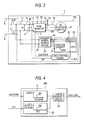
- Fig. 2 is a block diagram showing the details of the load control means 30 in Embodiment 1.
- the load control means 30 has a voltage generation table 31.
- This load control means 30 receives the inverter state signal ICS-FD/FB, and it generates load start signals LDS1 and LDS2 by utilizing the voltage generation table 31.
- the load start signal LDS1 is a start signal for the in-room heater 26, while the load start signal LDS2 is a start signal for the in-room cooler 27.
- the voltage generation table 31 sets the load start signals LDS1 and LDS2 at ON signals and simultaneously brings the in-room heater 26 and in-room cooler 27 into ON states.
- the inverter 12 has fallen into the inverter stop state SC, this inverter 12 does not generate the converted output voltage, and the inverter state signal ICS-FD/FB becomes a low level signal, so that the load start signals LDS1 and LDS2 become OFF signals, and both the in-room heater 26 and the in-room heater 27 are brought into OFF states.
- Embodiment 1 in a state where the power running command FD is given to the inverter 12, and a state where the regenerative braking command FB is given to the inverter 12, the inverter state signal ICS-FD/FB becomes a high level signal, and both the load start signals LDS1 and LDS2 of the load control means 30 become ON signals on the basis of this inverter state signal ICS-FD/FB, whereby the in-room heater 26 and the in-room cooler 27 fall into ON states, and the in-room heater 26 and in-room cooler 27 are simultaneously fed with electric power from the auxiliary power source device 22.
- the adjustment temperatures of the in-room heater 26 and in-room cooler 27 are both set at a comfortable temperature, for example, 20 (°C), whereby by way of example, in summer, the interior of the car room is brought into a cooled state as compared with the exterior of the car room, and in winter, the interior of the car room is brought into a heated state as compared with the exterior of the car room, so that the comfortable temperature can be established.
- the inverter 12 and the load 25 of the auxiliary power source device 22 form the regenerative load of another electric train connected to the identical DC power feed line 5, and the regenerative energy of the other electric train can be consumed.
- the load 25 of the auxiliary power source device 22 consumes the regenerative energy of the inverter 12.
- the inverter state signal ICS-FD/FB becomes a low level signal, and both the load start signals LDS1 and LDS2 of the load control means 30 become OFF signals, so that both the in-room heater 26 and in-room cooler 27 of the load 25 of the auxiliary power source device 22 are brought into OFF states.
- the load control means 30 brings both the in-room heater 26 and in-room cooler 27 forming the load 25 of the auxiliary power source device 22, into the ON states, so that the inverter 12 and the load 25 of the auxiliary power source device 22 form the regenerative load of the other electric train and can consume the regenerative energy of the other electric train.
- the load control means 30 brings both the in-room heater 26 and in-room cooler 27 forming the load 25 of the auxiliary power source device 22, into the ON states, so that the load 25 of the auxiliary power source device 22 can be set as the regenerative load of the inverter 12.
- the load 25 of the auxiliary power source device 22 can be set as the regenerative load of the inverter 12, and the voltage rise of the DC power feed circuit 15 can be suppressed.
- the regenerative energy can be consumed without adding a brake chopper or an electric-double-layer capacitor to the control apparatus 10, to bring forth the advantages that the wear of a brake shoe which affords mechanical braking during regenerative braking can be avoided, and that the control apparatus 10 can be made small in size.
- the in-room heater 26 and in-room cooler 27 of the electric train 1 are simultaneously turned ON/OFF by the load control means 30.
- a temperature within the car room of the electric train 1 can be adjusted to a comfortable temperature by appropriately setting the adjustment setting temperatures of the heater and the cooler.
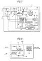
- Fig. 3 is a block diagram showing Embodiment 2 of a control apparatus for an electric train according to this invention
- Fig. 4 is a block diagram showing the details of load control means 30A for use in this embodiment 2.
- Embodiment 1 the in-room heater 26 and the in-room cooler 27 which form the load 25 of the auxiliary power source device 22 are simultaneously ON/OFF-controlled by the load control means 30 on the basis of the inverter state signal ICS-FD/FB, whereas in this embodiment 2, detection means 20 for detecting the DC power feed information DIF of a DC power feed circuit 15 is added to the DC power feed circuit 15, and the in-room heater 26 and the in-room cooler 27 which form the load 25 of the auxiliary power source device 22 are simultaneously ON/OFF-controlled by the load control means 30A on the basis of the inverter state signal ICS-FD/FB and the DC power feed information DIF.
- the others are configured to be the same as in Embodiment 1.
- the in-room heater 26 and the in-room cooler 27 which form the load 25 of the auxiliary power source device 22 are simultaneously ON/OFF-controlled on the basis of the inverter state signal ICS-FD/FB and the DC power feed information DIF of the DC power feed circuit 15, so that the in-room heater 26 and the in-room cooler 27 which form the load 25 of the auxiliary power source device 22 can be controlled more exactly in accordance with a load state on the side of a DC power feed line 5.
- the control apparatus for the electric train in Embodiment 2 is indicated by reference sign 10A.
- This control apparatus 10A for the electric train is such that the detection means 20 is added to the control apparatus 10 in Embodiment 1.
- This detection means 20 is concretely a voltage sensor, which detects a DC voltage VD applied across a smoothing capacitor 17 and which supplies the load control means 30A with the DC power feed information DIF representative of the DC voltage VD.
- the load control means 30A in Embodiment 2 has a voltage generation table 32 and a logical product circuit (AND circuit) 33 in addition to a voltage generation table 31.
- the output of the voltage generation table 31 and the output of the voltage generation table 32 are both inputted to the logical product circuit 33, and this logical product circuit 33 generates load start signals LDS1 and LDS2.
- the DC power feed information DIF from the detection means 20 is supplied to the voltage generation table 32.
- This voltage generation table 32 outputs an ON signal when the DC voltage VD in the DC power feed circuit 15 has exceeded a predetermined voltage value VD1 greater than the prescribed voltage VD0 of the DC power feed line 5.
- the predetermined voltage value VD1 is set at 1850 - 1900 (V)
- the predetermined voltage value VD1 is set at 850 - 900 (V).
- the voltage generation table 32 of the load control means 30A outputs the ON signal when the DC voltage VD in the DC power feed circuit 15 has exceeded the predetermined voltage value VD1.
- the inverter 12 converts DC electric power to three-phase AC electric power and feeds the AC electric power to an AC electric motor 11, so that the DC voltage VD lowers.
- the DC voltage VD exceeds the predetermined voltage value VD1.
- this inverter 12 converts three-phase AC electric power generated by the AC electric motor 11, into DC electric power and feeds the DC electric power to the DC power feed circuit 15. Therefore, if a regenerative load on the side of the DC power feed line 5 is low, the DC voltage VD rises and exceeds the predetermined voltage value VD1.
- the voltage generation table 31 outputs an ON signal on the basis of the inverter state signal ICS-FD/FB, when this inverter state signal ICS-FD/FB has become a high level signal, in other words, when the inverter 12 is generating a converted output voltage, in the state where the power running command FD is given to the inverter 12, and in the state where the regenerative braking command FB is given to the inverter 12.
- the logical product circuit 33 sets the load start signals LDS1 and LDS2 at ON signals and brings both the in-room heater 26 and in-room cooler 27 of the load 25 into ON states.
- the ON signal fails to be outputted from the voltage generation table 32, so that both the load start signals LDS1 and LDS2 become OFF signals, and the power feed to the in-room heater 26 and in-room cooler 27 of the load 25 is stopped.
- the ON signal fails to be outputted from the voltage generation table 31, so that the power feed to the in-room heater 26 and in-room cooler 27 of the load 25 is similarly stopped.
- Embodiment 2 as in Embodiment 1, there are attained the advantages that regenerative energy can be effectively consumed, that the wear of a brake shoe which affords mechanical braking during regenerative braking can be avoided, and that the control apparatus 10A can be made small in size, without adding a brake chopper or an electric-double-layer capacitor to the control apparatus 10A.
- the in-room cooler and in-room heater of the load 25 of the auxiliary power source device 22 are started on the basis of also the DC power feed information DIF of the DC power feed circuit 15, and hence, only when the load on the side of the DC power feed line 5 is low, the load 25 of the auxiliary power source device 22 can be started, to attain the advantage that the energy can be effectively consumed.
- the detection means 20 has been configured as the voltage sensor so as to detect the DC voltage VD from the voltage of the smoothing capacitor 17.
- the DC voltage of the DC power feed line 5 can also be detected on the input side of a reactor 16, and the same advantages can be attained in this case.
- preciser DC power feed information DIF can be obtained in such a way that a current sensor is disposed in series with the reactor 16, that the DC electric power of the DC power feed circuit 15 is calculated on the basis of the voltage sensor output and current sensor output of the detection means 20, and that the calculated DC electric power is used as the DC power feed information DIF.
- Fig. 5 is a block diagram showing Embodiment 3 of a control apparatus for an electric train according to this invention
- Fig. 6 is a block diagram showing the details of load control means 30B for use in this embodiment 3.
- the control apparatus for the electric train in this embodiment 3 is indicated by reference sign 10B.
- This control apparatus 10B for the electric train is such that the load control apparatus 30A in Embodiment 2 is replaced with the load control means 30B, and the others are configured to be the same as in Embodiment 2.
- the load control means 30B for use in Embodiment 3 has voltage generation tables 31 and 32 and a logical product circuit 33, likewise to the load control means 30A used in Embodiment 2, but an inverter state signal ICS-FD is inputted to the voltage generation table 31.
- the inverter state signal ICS-FD is a signal representative of a powering command signal FD which is given to an inverter 12, and this inverter state signal ICS-FD becomes a high level signal in a state where the powering command signal FD is given to the inverter 12, whereas it becomes a low level signal in both a state where a regenerative braking command FB is given to the inverter 14 and a state where the inverter 12 has fallen into an inverter stop state SC.
- the voltage generation table 31 of the load control means 30B outputs an ON signal when the inverter state signal ICS-FD has become the high level signal, in other words, when the inverter 12 is generating a converted output voltage of AC, in the state where the power running command FD is given to the inverter 12.
- the inverter state signal ICS-FD becomes the low level signal, and hence, the voltage generation table 31 outputs an OFF signal.
- the voltage generation table 32 of the load control means 30B outputs an ON signal when a DC voltage VD in a DC power feed circuit 15 has exceeded a predetermined voltage value VD1.
- this inverter 12 converts DC electric power from the DC power feed circuit 15, into three-phase AC electric power and feeds the AC electric power to an AC electric motor 11, so that the DC voltage VD lowers.
- the DC voltage VD exceeds the predetermined voltage value VD1.
- the logical product circuit 33 in Embodiment 3 sets load start signals LDS1 and LDS2 at ON signals, so as to simultaneously start the in-room heater 26 and in-room cooler 27 of the load 25 of an auxiliary power source device 22.
- the load start signals LDS1 and LDS2 become the ON signals to simultaneously start the in-room heater 26 and in-room cooler 27 of the load 25, whereby the DC energy of the DC power feed circuit 15 is effectively consumed.
- Embodiment 3 as in Embodiment 1, there are attained the advantages that the regenerative energy can be effectively consumed, that the wear of a brake shoe which affords mechanical braking during regenerative braking can be avoided, and that the control apparatus 10B can be made small in size, without adding a brake chopper or an electric-double-layer capacitor to the control apparatus 10B.
- the in-room heater 26 and the in-room cooler 27 are simultaneously started in accordance with the DC power feed information DIF of the DC power feed circuit 15, so that only when the load on the side of the DC power feed line 5 is low, the in-room heater 26 and in-room cooler 27 of the load 25 of the auxiliary power source device 22 can be started.
- Fig. 7 is a block diagram showing Embodiment 4 of a control apparatus for an electric train according to this invention
- Fig. 8 is a block diagram showing the details of load control means 30C in this embodiment 4.
- the control apparatus for the electric train in this embodiment 3 is indicated by reference sign 10C.
- This control apparatus 10C for the electric train is such that the load control means 30A in Embodiment 2 is replaced with the load control means 30C, and the others are configured to be the same as in Embodiment 2.
- the load control means 30C for use in Embodiment 4 has voltage generation tables 31 and 32 and a logical product circuit 33, likewise to the load control means 30A used in Embodiment 2, but an inverter state signal ICS-FB is inputted to the voltage generation table 31.
- the inverter state signal ICS-FB is a signal representative of a regenerative braking command FB which is given to an inverter 12, and this inverter state signal ICS-FB becomes a high level signal in a state where the regenerative braking command FB is given to the inverter 14, whereas it becomes a low level signal in both a state where a power running command FD is given to the inverter 12 and a state where the inverter 12 has fallen into an inverter stop state SC.
- the voltage generation table 31 of the load control means 30C outputs an ON signal when the inverter state signal ICS-FB has become the high level signal, in other words, when the inverter 12 is generating a DC converted output voltage, in the state where the regenerative braking command FB is given to the inverter 12.
- the inverter state signal ICS-FB becomes the low level signal, and hence, the voltage generation table 31 outputs an OFF signal.
- the voltage generation table 32 of the load control means 30C outputs an ON signal when a DC voltage VD in a DC power feed circuit 15 has exceeded a predetermined voltage value VD1 by way of example.
- this inverter 12 converts three-phase AC electric power generated by an AC electric motor 11, into DC electric power and feeds the DC electric power to the DC power feed circuit 15, so that if a regenerative load on the side of a DC power feed line 5 is low, the DC voltage VD of the DC power feed circuit 15 rises to exceed a predetermined voltage value VD1.
- the logical product circuit 33 in Embodiment 4 sets load start signals LDS1 and LDS2 at ON signals, so as to simultaneously start the in-room heater 26 and in-room cooler 27 of the load 25 of an auxiliary power source device 22.
- the load start signals LDS1 and LDS2 become the ON signals to simultaneously start the in-room heater 26 and in-room cooler 27, whereby the regenerative energy of the DC power feed circuit 15 is effectively consumed.
- Embodiment 4 as in Embodiment 1, there are attained the advantages that the regenerative energy can be effectively consumed, that the wear of a brake shoe which affords mechanical braking during regenerative braking can be avoided, and that the control apparatus 10C can be made small in size, without adding a brake chopper or an electric-double-layer capacitor to the control apparatus 10C.
- the in-room heater 26 and the in-room cooler 27 are simultaneously started in accordance with the DC power feed information DIF of the DC power feed circuit 15, so that only when the load on the side of the DC power feed line 5 is low, the in-room heater 26 and in-room cooler 27 of the load 25 of the auxiliary power source device 22 can be started.
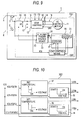
- Fig. 9 is a block diagram showing Embodiment 5 of a control apparatus for an electric train according to this invention, while Fig. 10 is a block diagram showing the details of load control means 30D for use in this embodiment 5.
- the control apparatus for the electric train in this embodiment 5 is indicated by reference sign 10D.
- This control apparatus 10D for the electric train has the load control means 30D, by which an in-room heater 26 and an in-room cooler 27 that are included in the load 25 of an auxiliary power source device 22 are controlled.
- the load control means 30D is supplied with an inverter state signal ICS from an inverter 12, and this inverter state signal ICS includes an inverter state signal ICS-FD/FB/SC and an inverter state signal ICS-FD/FB.
- the load control means 30D ON/OFF-controls the in-room heater 26 and the in-room cooler 27 and also controls the load states thereof, on the basis of these inverter state signals ICS-FD/FB/SC and ICS-FD/FB.
- the others are configured to be the same as in Embodiment 1.
- the inverter state signal ICS-FD/FB/SC becomes a high level signal in any of a state where a power running command FD is given to the inverter 12, a state where a regenerative braking command FB is given to the inverter 12, and a state where the inverter 12 has fallen into an inverter stop state SC.
- the load control means 30D has four voltage generation tables 34, 35, 36 and 37.
- the voltage generation table 34 is supplied with the inverter state signal ICS-FD/FB/SC.
- the inverter state signal ICs-FD/FB/SC becomes the high level signal in any of the state where the power running command FD is given to the inverter 12, the state where the regenerative braking command FB is given to the inverter 12, and the state where the inverter 12 has fallen into the inverter stop state SC, so that the voltage generation table 34 sets a load start signal LDSa at an ON signal normally irrespective of whether the inverter 12 is generating a converted output voltage or is not generating the converted output voltage.
- the voltage generation table 35 is supplied with the inverter state signal ICS-FD/FB.
- This inverter state signal ICS-FD/FB becomes a high level signal in the state where the power running command FD is given to the inverter 12, and the state where the regenerative braking command FB is given to the inverter 12.
- the voltage generation table 35 sets a load start signal LDSb at an ON signal on the basis of the inverter state signal ICS-FD/FB, when this inverter state signal ICS-FD/FB has become the high level signal, in other words, when the inverter 12 is generating the converted output voltage.
- the voltage generation tables 36 and 37 are supplied with the inverter state signal ICS-FD/FB.
- the voltage generation table 36 sets a high load signal LDTa at an ON signal on the basis of the inverter state signal ICS-FD/FB, when this inverter state signal ICS-FD/FB has become the high level signal, in other words, when the inverter 12 is generating the converted output voltage.
- the voltage generation table 37 sets a high load signal LDTb at an ON signal on the basis of the inverter state signal ICS-FD/FB, when this inverter state signal ICS-FD/FB has become the high level signal, in other words, when the inverter 12 is generating the converted output voltage.
- the high load signals LDTa and LDTb change the in-room heater 26 and the in-room cooler 27 from low load states into high load states when they have become the ON signals, respectively.
- the load start signals LDSa and LDSb and the high load signals LDTa and LDTb which are outputted from the load control means 30D are set into the following first states in summer:
- the load start signal LDSa of the voltage generation table 34 normally becomes the ON signal on the basis of the inverter state signal ICS-FD/FB/SC, and the in-room cooler 27 is normally started by the ON signal of the load start signal LDSa.
- the inverter state signal ICS-FD/FB becomes the high level signal, and hence, all of the load start signal LDSb and the high load signals LDTa and LDTb which are outputted from the respective voltage generation tables 35, 36 and 37 become the ON signals.
- the in-room heater 26 is started by the ON signal of the load start signal LDSb.
- the adjustment setting temperature of the in-room cooler 27 is lowered by the ON signal of the high load signal LDTa, and the in-room cooler 27 changes into the high load state.
- the adjustment setting temperature of the in-room heater 26 is raised by the ON signal of the high load signal LDTb, and the in-room heater 26 falls into the high load state.
- the in-room cooler 27 in summer, is normally held in the ON state on the basis of the inverter state signal ICS-FD/FB/SC, thereby to normally cool the interior of a car room.
- the in-room cooler 27 changes into the high load state, and the in-room heater 26 operates in the high load state, on the basis of the inverter state signal ICS-FD/FB. Since the in-room heater 26 falls into the high load state, the consumption energy of the in-room heater 26 increases. Besides, since the in-room cooler 27 falls into the high load state, the consumption energy of the in-room cooler 27 increases. Owing to the operations of the in-room cooler 27 and the in-room heater 26 in the high load states, the regenerative energy of a DC power feed circuit 15 can be consumed more.
- the load start signals LDSa and LDSb and the high load signals LDTa and LDTb which are outputted from the load control means 30D are set into the following second states in winter:
- the load start signal LDSa of the voltage generation table 34 normally becomes the ON signal on the basis of the inverter state signal ICS-FD/FB/SC, and the in-room heater 26 is normally started by the ON signal of the load start signal LDSa.
- the inverter state signal ICS-FD/FB becomes the high level signal, and hence, all of the load start signal LDSb and the high load signals LDTa and LDTb of the respective voltage generation tables 35, 36 and 37 become the ON signals.
- the in-room cooler 27 is started by the ON signal of the load start signal LDSb.
- the adjustment setting temperature of the in-room cooler 27 is lowered by the ON signal of the high load signal LDTa, and the in-room cooler 27 changes into the high load state.
- the adjustment setting temperature of the in-room heater 26 is raised by the ON signal of the high load signal LDTb, and the in-room heater 26 falls into the high load state.
- the in-room heater 26 is normally operated on the basis of the inverter state signal ICS-FD/FB/SC, thereby to normally heat the interior of the car room.
- the in-room heater 26 changes into the high load state, and the in-room cooler 27 operates in the high load state, on the basis of the inverter state signal ICS-FD/FB. Since the in-room heater 26 falls into the high load state, the consumption energy of the in-room heater 26 increases. Besides, since the in-room cooler 27 falls into the high load state, the consumption energy of the in-room cooler 27 increases. Owing to the operations of the in-room heater 26 and the in-room cooler 27 in the high load states, the regenerative energy of the DC power feed circuit 15 can be consumed more.
- Embodiment 5 when the power running command FD or the regenerative braking command FB is given to the inverter 12, the in-room heater 26 and the in-room cooler 27 are both operated in the high load states, and hence, the regenerative energy of the DC power feed circuit 15 is effectively consumed. Accordingly, also in Embodiment 5, as in Embodiment 1, there are attained the advantages that the regenerative energy can be effectively consumed, that the wear of a brake shoe which affords mechanical braking during regenerative braking can be avoided, and that the control apparatus 10D can be made small in size, without adding a brake chopper or an electric-double-layer capacitor to the control apparatus 10D. Besides, the adjustment setting temperatures of the in-room heater 26 and the in-room cooler 27 are simultaneously altered, thereby to attain the advantage that, while a pleasant in-room temperature is being realized, the regenerative energy of the DC power feed circuit 15 can be further consumed.
- the signals are set in the same states as in either summer or winter.
- the in-room heater 26 or the in-room cooler 27 is normally started by the voltage generation table 34, but in the inverter stop state SC, the adjustment setting temperature thereof is set in correspondence with spring or autumn, and the in-room heater 26 or the in-room cooler 27 which is started by the output LDSa of the voltage generation table 34 is brought into the low load state.
- Fig. 11 is a block diagram showing Embodiment 6 of a control apparatus for an electric train according to this invention
- Fig. 12 is a block diagram showing the details of load control means 30E for use in Embodiment 6.
- the control apparatus for the electric train in this embodiment 6 is indicated by reference sign 10E.
- This control apparatus 10E for the electric train has the load control means 30E, by which an in-room heater 26 and an in-room cooler 27 that form the load 25 of an auxiliary power source device 22 are controlled.
- the load control means 30E is supplied with an inverter state signal ICS from an inverter 12, and DC power feed information DIF from detection means 20.
- the inverter state signal ICS includes an inverter state signal ICS-FD/FB/SC and an inverter state signal ICS-FD/FB.
- the load control means 30E ON/OFF-controls the in-room heater 26 and the in-room cooler 27 and also controls the load states thereof, on the basis of these inverter state signals ICS-FD/FB/SC and ICS-FD/FB and the DC power feed information DIF.
- the others are configured to be the same as in Embodiment 1.
- the load control means 30E has four voltage generation tables 41, 42, 43 and 44.
- the voltage generation table 41 is supplied with the inverter state signal ICS-FD/FB/SC.
- the inverter state signal ICs-FD/FB/SC becomes a high level signal in any of a state where a power running command FD is given to the inverter 12, a state where a regenerative braking command FB is given to the inverter 12, and a state where the inverter 12 has fallen into an inverter stop state SC, so that the voltage generation table 41 sets a load start signal LDSa at an ON signal normally irrespective of whether the inverter 12 is generating a converted output voltage or is not generating the converted output voltage.
- the voltage generation table 42 is supplied with the inverter state signal ICS-FD/FB.
- This inverter state signal TCS-FD/FB becomes a high level signal in the state where the power running command FD is given to the inverter 12, and the state where the regenerative braking command FB is given to the inverter 12.
- the voltage generation table 42 sets a load start signal LDSb at an ON signal on the basis of the inverter state signal ICS-FD/FB, when this inverter state signal ICS-FD/FB has become the high level signal, in other words, when the inverter 12 is generating the converted output voltage.
- the voltage generation tables 43 and 44 are supplied with the DC power feed information DIF.
- the voltage generation table 43 generates a heater-set-temperature control signal LDT1 on the basis of the DC power feed information DIF, and the voltage generation table 44 generates a cooler-set-temperature control signal LDT2.
- the DC power feed information DIF is a signal which represents the DC voltage VD of a DC power feed circuit 15.
- the voltage generation table 43 enlarges the heater-set-temperature control signal LDT1 on the basis of the DC power feed information DIF and in proportion to the magnitude of the excess voltage value (VD - VD1), thereby to raise an adjustment setting temperature for the in-room heater 26 and to control this in-room heater 26 into a high load state.
- the voltage generation table 44 lowers the cooler-set-temperature control signal LDT2 on the basis of the DC power feed information DIF and in proportion to the magnitude of the excess voltage value (VD - VD1), thereby to lower an adjustment setting temperature for the in-room cooler 27 and to control this in-room cooler 27 into a high load state.
- Embodiment 5 on the basis of the inverter state signal ICS-FD/FB, the in-room heater 26 or the in-room cooler 27 has been ON/OFF-controlled, and conjointly, the in-room heater 26 and the in-room cooler 27 have been controlled so as to change their load states, whereas in this embodiment 6, the inverter state signal ICS-FD/FB and the DC power feed information DIF are supplied to the load control means 30E, and the in-room heater 26 or the in-room cooler 27 is ON/OFF-controlled on the basis of the inverter state signal ICS-FD/FB, and conjointly, the load states of the in-room heater 26 and the in-room cooler 27 are changed on the basis of the DC power feed information DIF.
- the inverter state signal ICS-FD/FB and the DC power feed information DIF are supplied to the load control means 30E, and the in-room heater 26 or the in-room cooler 27 is ON/OFF-controlled on the basis of the inverter state signal ICS-FD/FB, and conjointly, the load
- the load start signals LDSa and LDSb which are outputted from the load control means 30E are set into the following first states in summer:
- the load start signal LDSa of the voltage generation table 41 normally becomes the ON signal on the basis of the inverter state signal ICS-FD/FB/SC, and the in-room cooler 27 is normally started by the ON signal of the load start signal LDSa.
- the load start signal LDSb of the voltage generation table 42 becomes the ON signal.
- the in-room heater 26 is started by the ON signal of the load start signal LDSb.
- the heater-set-temperature control signal LDT1 rises in proportion to the magnitude of the excess voltage value (VD - VD1), and the consumption energy of the in-room heater 26 increases in proportion to the excess voltage value (VD - VD1).
- the cooler-set-temperature control signal LDT2 lowers, and the consumption energy of the in-room cooler 27 increases in proportion to the excess voltage value (VD - VD1).
- the in-room cooler 27 is normally operated on the basis of the inverter state signal ICS-FD/FB/SC, thereby to normally cool the interior of a car room.
- the power running command FD or the regenerative braking command FB is given to the inverter 12 in the ON state of the in-room cooler 27, the in-room heater 26 is brought into its ON state on the basis of the inverter state signal ICS-FD/FB.
- the load start signals LDSa and LDSb which are outputted from the load control means 30E are set into the following second states in winter:
- the load start signal LDSa of the voltage generation table 41 normally becomes the ON signal on the basis of the inverter state signal ICS-FD/FB/SC, and the in-room heater 26 is normally started by the ON signal of the load start signal LDSa.
- the load start signal LDSb of the voltage generation table 42 becomes the ON signal.
- the in-room cooler 27 is started by the ON signal of the load start signal LDSb.
- the heater-set-temperature control signal LDT1 rises in proportion to the magnitude of the excess voltage value (VD - VD1), and the cooler-set-temperature control signal LDT2 lowers, whereby the in-room heater 26 and the in-room cooler 27 are brought into the high load states.
- the in-room heater 26 in winter, is normally held in the ON state on the basis of the inverter state signal ICS-FD/FB/SC, thereby to normally heat the interior of the car room.
- the in-room cooler 27 is brought into its ON state on the basis of the inverter state signal ICS-FD/FB.
- Embodiment 6 as in Embodiment 1, there are attained the advantages that the regenerative energy can be effectively consumed, that the wear of a brake shoe which affords mechanical braking during regenerative braking can be avoided, and that the control apparatus 10E can be made small in size, without adding a brake chopper or an electric-double-layer capacitor to the control apparatus 10E.
- the adjustment setting temperatures of the in-room heater 26 and the in-room cooler 27 are simultaneously altered, thereby to attain the advantage that, while a pleasant in-room temperature is being realized, the regenerative energy of the DC power feed circuit 15 can be further consumed.
- the signals are set in the same states as in either summer or winter.
- the in-room heater 26 or the in-room cooler 27 is normally started by the voltage generation table 41, but in an inverter stop state SC, the adjustment setting temperature thereof is set in correspondence with spring or autumn, and the in-room heater 26 or the in-room cooler 27 which is started by the output LDSa of the voltage generation table 41 is brought into a low load state.
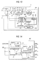
- Fig. 13 is a block diagram showing Embodiment 7 of a control apparatus for an electric train according to this invention
- Fig. 14 is a block diagram showing the details of load control means 30F for use in Embodiment 7.
- the control apparatus for the electric train in this embodiment 7 is indicated by reference sign 10F.
- This control apparatus 10F for the electric train controls an in-room heater 26 and an in-room cooler 27 which form the load 25 of an auxiliary power source device 22, by the load control means 30F.
- This load control means 30F has four voltage generation tables 41, 42, 43 and 44 likewise to the load control means 30E of Embodiment 6, and the voltage generation table 42 is supplied with DC power feed information DIF.
- the voltage generation table 42 sets a load start signal LDSb at an ON signal on the basis of the DC power feed information DIF.
- the others are configured to be the same as in Embodiment 6.
- the load start signal LDSa of the voltage generation table 41 normally becomes an ON signal on the basis of an inverter state signal ICS-FD/FB/SC, and the in-room cooler 27 is normally started by the ON signal of the load start signal LDSa.
- a DC voltage VD exceeds a predetermined voltage value VD1
- the load start signal LDSb of the voltage generation table 42 becomes the ON signal
- the in-room heater 26 is started by the ON signal of the load start signal LDSb.
- the in-room cooler 27 is normally operated on the basis of the inverter state signal ICS-FD/FB/SC, thereby to normally cool the interior of a car room.
- the in-room heater 26 is brought into its ON state on the basis of the DC power feed information DIF.
- the load start signal LDSa of the voltage generation table 41 normally becomes the ON signal on the basis of an inverter state signal ICS-FD/FB/SC, and the in-room heater 26 is normally started by the ON signal of the load start signal LDSa.
- the load start signal LDSb of the voltage generation table 42 becomes the ON signal, and the in-room cooler 27 is started by the ON signal of the load start signal LDSb.
- the in-room heater 26 normally becomes the ON state on the basis of the inverter state signal ICS-FD/FB/SC, thereby to normally heat the interior of the car room.
- the in-room cooler 27 is brought into its ON state on the basis of the DC power feed information DIF.
- Embodiment 7 when the DC voltage VD exceeds the predetermined voltage value VD1, the in-room heater 26 and the in-room cooler 27 are both operated in the high load states, and hence, the regenerative energy of the DC power feed circuit 15 is effectively consumed. Accordingly, also in Embodiment 7, as in Embodiment 1, there are attained the advantages that the regenerative energy can be effectively consumed, that the wear of a brake shoe which affords mechanical braking during regenerative braking can be avoided, and that the control apparatus 10F can be made small in size, without adding a brake chopper or an electric-double-layer capacitor to the control apparatus 10F. Besides, the adjustment setting temperatures of the in-room heater 26 and the in-room cooler 27 are simultaneously altered, thereby to attain the advantage that, while a pleasant in-room temperature is being realized, the regenerative energy of the DC power feed circuit 15 can be further consumed.
- the signals are set in the same states as in either summer or winter.
- the in-room heater 26 or the in-room cooler 27 is normally started by the voltage generation table 41, but in an inverter stop state SC, the adjustment setting temperature thereof is set in correspondence with spring or autumn, and the in-room heater 26 or the in-room cooler 27 which is started by the output LDSa of the voltage generation table 41 is brought into a low load state.
- a control apparatus for an electric train according to this invention is utilized in various electric trains in which inverters are mounted.
Landscapes
- Engineering & Computer Science (AREA)
- Power Engineering (AREA)
- Transportation (AREA)
- Mechanical Engineering (AREA)
- Life Sciences & Earth Sciences (AREA)
- Sustainable Development (AREA)
- Sustainable Energy (AREA)
- Electric Propulsion And Braking For Vehicles (AREA)
- Earth Drilling (AREA)
- Placing Or Removing Of Piles Or Sheet Piles, Or Accessories Thereof (AREA)
Applications Claiming Priority (1)
| Application Number | Priority Date | Filing Date | Title |
|---|---|---|---|
| PCT/JP2006/309650 WO2007132515A1 (ja) | 2006-05-15 | 2006-05-15 | 電気車の制御装置 |
Publications (2)
| Publication Number | Publication Date |
|---|---|
| EP2018995A1 true EP2018995A1 (de) | 2009-01-28 |
| EP2018995A4 EP2018995A4 (de) | 2013-04-24 |
Family
ID=38693618
Family Applications (1)
| Application Number | Title | Priority Date | Filing Date |
|---|---|---|---|
| EP06732581.1A Withdrawn EP2018995A4 (de) | 2006-05-15 | 2006-05-15 | Steuervorrichtung für elektroauto |
Country Status (8)
| Country | Link |
|---|---|
| US (1) | US7808195B2 (de) |
| EP (1) | EP2018995A4 (de) |
| JP (1) | JP4940234B2 (de) |
| KR (1) | KR100973889B1 (de) |
| CN (1) | CN101321645B (de) |
| CA (1) | CA2642262C (de) |
| RU (1) | RU2383684C1 (de) |
| WO (1) | WO2007132515A1 (de) |
Cited By (2)
| Publication number | Priority date | Publication date | Assignee | Title |
|---|---|---|---|---|
| CN103201132A (zh) * | 2010-11-19 | 2013-07-10 | 三菱电机株式会社 | 车辆用辅助电源装置 |
| RU2492071C1 (ru) * | 2009-07-15 | 2013-09-10 | Мицубиси Электрик Корпорейшн | Устройство управления ходом электромоторного вагона |
Families Citing this family (23)
| Publication number | Priority date | Publication date | Assignee | Title |
|---|---|---|---|---|
| JP2009225630A (ja) * | 2008-03-18 | 2009-10-01 | Toshiba Corp | 負荷調整装置を有する電気車 |
| JP5207908B2 (ja) * | 2008-10-06 | 2013-06-12 | 三菱電機株式会社 | 電気車制御装置 |
| KR101034084B1 (ko) * | 2008-12-05 | 2011-05-13 | 현대자동차주식회사 | 하이브리드 차량의 2차 소손 방지 장치 및 방지 방법 |
| JP5293390B2 (ja) * | 2009-05-08 | 2013-09-18 | コニカミノルタ株式会社 | 電源制御装置、および画像形成装置 |
| CN102574532B (zh) * | 2009-06-12 | 2016-01-20 | 三菱电机株式会社 | 车辆用电力变换装置 |
| US8482151B2 (en) * | 2009-07-02 | 2013-07-09 | Electrical Power Worx Corp. | Auxiliary power systems and methods thereof |
| KR101231800B1 (ko) * | 2011-03-18 | 2013-02-08 | 한국철도기술연구원 | 모선에 의해 공급되는 주전원과 모터의 회생제동에 의해 공급되는 보조전원의 이중 전원을 가지는 정지형 인버터 작동 방법 |
| WO2014002260A1 (ja) * | 2012-06-29 | 2014-01-03 | 三菱電機株式会社 | 交流電気車の制御装置 |
| EP2886386B1 (de) * | 2012-08-14 | 2017-09-27 | Mitsubishi Electric Corporation | Zuginformationsverwaltungsvorrichtung und steuerverfahren für diese vorrichtung |
| CN102866288B (zh) * | 2012-10-17 | 2016-03-02 | 株洲南车时代电气股份有限公司 | 一种电压检测装置和一种电力机车供电系统 |
| JP5395947B2 (ja) * | 2012-11-26 | 2014-01-22 | 株式会社東芝 | 負荷調整装置を有する電気車 |
| JP5840309B2 (ja) | 2013-01-17 | 2016-01-06 | 三菱電機株式会社 | 車両用空調制御装置 |
| JP6193117B2 (ja) * | 2013-12-27 | 2017-09-06 | 株式会社東芝 | 車両空調制御装置 |
| JP6431298B2 (ja) * | 2014-06-24 | 2018-11-28 | 株式会社東芝 | 空調制御装置 |
| JP6226914B2 (ja) * | 2015-06-12 | 2017-11-08 | ファナック株式会社 | 非常停止時にサーボモータを制御して停止させるサーボモータ停止制御装置 |
| US10195945B2 (en) * | 2015-07-29 | 2019-02-05 | Nissan Motor Co., Ltd. | Control device for electric vehicle and control method for electric vehicle |
| CN109664771A (zh) * | 2017-10-17 | 2019-04-23 | 株洲中车时代电气股份有限公司 | 一种带无火回送功能的牵引变流装置 |
| JP6671440B1 (ja) * | 2018-09-28 | 2020-03-25 | 株式会社Subaru | ジャンクションボックス制御装置 |
| CN109532568B (zh) * | 2019-01-09 | 2023-05-26 | 西南交通大学 | 一种电气化铁路列车三轨供电控制系统 |
| DE102019210770B4 (de) * | 2019-07-19 | 2021-03-11 | Bombardier Transportation Gmbh | Betreiben eines Schienenfahrzeugs beim Passieren von Trennstellen in einer fahrzeugexternen Stromversorgung |
| WO2021024462A1 (ja) * | 2019-08-08 | 2021-02-11 | 三菱電機株式会社 | データ収集システム、補助電源装置、モニタ装置およびデータ収集方法 |
| KR102829847B1 (ko) * | 2020-05-11 | 2025-07-04 | 현대자동차주식회사 | 친환경 차량의 회생제동 제어 시스템 |
| US12558965B2 (en) * | 2023-05-31 | 2026-02-24 | Fca Us Llc | Deployable resistor to dissipate power during regenerative braking for electrified vehicle |
Family Cites Families (33)
| Publication number | Priority date | Publication date | Assignee | Title |
|---|---|---|---|---|
| SU58669A1 (ru) * | 1939-04-08 | 1939-11-30 | Н.Н. Николаев | Электрический молот |
| GB1163370A (en) * | 1967-12-29 | 1969-09-04 | Conmaco Inc | Pile Driving Hammer |
| US3665495A (en) * | 1970-06-01 | 1972-05-23 | Power Systems And Controls Inc | No break power system |
| SU497405A1 (ru) * | 1970-08-26 | 1975-12-30 | Институт Горного Дела Со Ан Ссср | Электромагнитный молот |
| JPS57183201A (en) * | 1981-05-06 | 1982-11-11 | Mitsubishi Electric Corp | Suppressing method for power peak load of electric motor vehicle |
| JPS6271404A (ja) * | 1985-09-24 | 1987-04-02 | Toshiba Corp | 電気車用過電圧保護装置 |
| JPH01259701A (ja) * | 1988-04-08 | 1989-10-17 | Toshiba Corp | 車両用電源装置 |
| JP3000858B2 (ja) * | 1994-09-01 | 2000-01-17 | 株式会社日立製作所 | 電気車の制御装置 |
| JP3487952B2 (ja) * | 1995-04-14 | 2004-01-19 | 株式会社日立製作所 | 電気自動車の駆動装置及び駆動制御方法 |
| US6177734B1 (en) * | 1998-02-27 | 2001-01-23 | Isad Electronic Systems Gmbh & Co. Kg | Starter/generator for an internal combustion engine, especially an engine of a motor vehicle |
| JP3345249B2 (ja) * | 1996-02-01 | 2002-11-18 | 三菱電機株式会社 | 電気車制御装置 |
| JP3560720B2 (ja) * | 1996-03-06 | 2004-09-02 | 東芝トランスポートエンジニアリング株式会社 | 車両用電源装置 |
| JP3274377B2 (ja) * | 1996-12-25 | 2002-04-15 | 三菱電機株式会社 | 負荷短絡故障の検出方法及びその装置と電動パワーステアリング装置 |
| JP3478193B2 (ja) * | 1999-05-24 | 2003-12-15 | トヨタ自動車株式会社 | 電源監視装置 |
| JP3808701B2 (ja) * | 2000-12-20 | 2006-08-16 | 株式会社東芝 | 車両用電源装置及びそれに対する制御装置 |
| JP3795803B2 (ja) | 2001-12-25 | 2006-07-12 | 株式会社東芝 | 電気車制御装置 |
| JP4023171B2 (ja) * | 2002-02-05 | 2007-12-19 | トヨタ自動車株式会社 | 負荷駆動装置、負荷駆動装置における電力貯蔵装置の充電制御方法および充電制御をコンピュータに実行させるためのプログラムを記録したコンピュータ読取可能な記録媒体 |
| JP2004104976A (ja) | 2002-09-12 | 2004-04-02 | Toshiba Corp | 電力変換装置 |
| JP2004155264A (ja) * | 2002-11-05 | 2004-06-03 | Denso Corp | 車両用空調装置 |
| JP2004248432A (ja) * | 2003-02-14 | 2004-09-02 | Toyota Motor Corp | 駆動装置およびこれを備える自動車 |
| KR100527184B1 (ko) * | 2003-07-07 | 2005-11-08 | 현대자동차주식회사 | 전기자동차의 공조 시스템을 이용한 회생 제동 방법 |
| US7439634B2 (en) * | 2004-08-24 | 2008-10-21 | Honeywell International Inc. | Electrical starting, generation, conversion and distribution system architecture for a more electric vehicle |
| RU2282029C2 (ru) * | 2004-09-23 | 2006-08-20 | Новосибирский государственный технический университет | Электромолот |
| US7256513B2 (en) * | 2004-12-02 | 2007-08-14 | General Electric Company | Locomotive auxiliary power system |
| FR2889370B1 (fr) * | 2005-07-29 | 2007-09-07 | Valeo Equip Electr Moteur | Procede de commande d'un onduleur de tension polyphase |
| JP4517984B2 (ja) * | 2005-09-01 | 2010-08-04 | トヨタ自動車株式会社 | ハイブリッド自動車 |
| RU2315181C2 (ru) * | 2005-12-23 | 2008-01-20 | Новосибирский государственный технический университет | Электромолот |
| US20070151272A1 (en) * | 2006-01-03 | 2007-07-05 | York International Corporation | Electronic control transformer using DC link voltage |
| RU54381U1 (ru) * | 2006-01-10 | 2006-06-27 | Новосибирский государственный технический университет | Электромолот |
| JP4491434B2 (ja) * | 2006-05-29 | 2010-06-30 | トヨタ自動車株式会社 | 電力制御装置およびそれを備えた車両 |
| US20080121136A1 (en) * | 2006-11-28 | 2008-05-29 | General Electric Company | Hybrid locomotive and method of operating the same |
| JP4513812B2 (ja) * | 2007-01-04 | 2010-07-28 | トヨタ自動車株式会社 | 車両の電源装置および車両 |
| US7535116B2 (en) * | 2007-04-16 | 2009-05-19 | General Electric Company | System and method for controlling an output of an auxiliary power source of a diesel powered system |
-
2006
- 2006-05-15 KR KR1020087015460A patent/KR100973889B1/ko not_active Expired - Fee Related
- 2006-05-15 CN CN2006800420980A patent/CN101321645B/zh not_active Expired - Fee Related
- 2006-05-15 JP JP2008515403A patent/JP4940234B2/ja not_active Expired - Fee Related
- 2006-05-15 US US12/063,748 patent/US7808195B2/en not_active Expired - Fee Related
- 2006-05-15 CA CA2642262A patent/CA2642262C/en not_active Expired - Fee Related
- 2006-05-15 WO PCT/JP2006/309650 patent/WO2007132515A1/ja not_active Ceased
- 2006-05-15 EP EP06732581.1A patent/EP2018995A4/de not_active Withdrawn
-
2008
- 2008-07-30 RU RU2008131597/03A patent/RU2383684C1/ru not_active IP Right Cessation
Cited By (3)
| Publication number | Priority date | Publication date | Assignee | Title |
|---|---|---|---|---|
| RU2492071C1 (ru) * | 2009-07-15 | 2013-09-10 | Мицубиси Электрик Корпорейшн | Устройство управления ходом электромоторного вагона |
| CN103201132A (zh) * | 2010-11-19 | 2013-07-10 | 三菱电机株式会社 | 车辆用辅助电源装置 |
| CN103201132B (zh) * | 2010-11-19 | 2015-09-30 | 三菱电机株式会社 | 车辆用辅助电源装置 |
Also Published As
| Publication number | Publication date |
|---|---|
| CN101321645A (zh) | 2008-12-10 |
| KR20080089571A (ko) | 2008-10-07 |
| US7808195B2 (en) | 2010-10-05 |
| RU2383684C1 (ru) | 2010-03-10 |
| KR100973889B1 (ko) | 2010-08-03 |
| JPWO2007132515A1 (ja) | 2009-09-17 |
| US20100147184A1 (en) | 2010-06-17 |
| RU2008131597A (ru) | 2010-02-10 |
| CA2642262C (en) | 2012-01-10 |
| WO2007132515A1 (ja) | 2007-11-22 |
| EP2018995A4 (de) | 2013-04-24 |
| HK1125077A1 (en) | 2009-07-31 |
| CN101321645B (zh) | 2011-03-30 |
| CA2642262A1 (en) | 2007-11-22 |
| JP4940234B2 (ja) | 2012-05-30 |
Similar Documents
| Publication | Publication Date | Title |
|---|---|---|
| CA2642262C (en) | Control apparatus for electric train | |
| US7246686B2 (en) | Power supply for elevator systems having variable speed drives | |
| JP4568169B2 (ja) | 電気車制御装置 | |
| CA2783782C (en) | Propulsion control apparatus | |
| JP4713690B2 (ja) | 電気車の電力変換装置 | |
| CA2901956C (en) | Main conversion device for electric vehicle | |
| CN102416878A (zh) | 铁道车辆的发电系统 | |
| JPH02219401A (ja) | 電気車の制御装置 | |
| CN111332122B (zh) | 采用分布式小功率电源模块的供电系统 | |
| RU2383450C1 (ru) | Устройство управления для электропоезда | |
| JP2011050196A (ja) | 制御方法及び制御装置 | |
| HK1125077B (en) | Electric car control apparatus | |
| CN110970958A (zh) | 一种用于中低速磁悬浮列车的充电机 | |
| KR100744482B1 (ko) | 지하철 변전소의 회생인버터 직류링크단 전압안정화장치 | |
| JP2018050406A (ja) | 補助電源装置 | |
| KR101322324B1 (ko) | 순간정전 보상 전력회생 시스템이 적용된 절전형 승강기 | |
| JP2023042118A (ja) | 電力変換器の制御装置および制御方法 | |
| JP2011152040A (ja) | 電気車の電力変換装置 |
Legal Events
| Date | Code | Title | Description |
|---|---|---|---|
| PUAI | Public reference made under article 153(3) epc to a published international application that has entered the european phase |
Free format text: ORIGINAL CODE: 0009012 |
|
| 17P | Request for examination filed |
Effective date: 20081021 |
|
| AK | Designated contracting states |
Kind code of ref document: A1 Designated state(s): AT BE BG CH CY CZ DE DK EE ES FI FR GB GR HU IE IS IT LI LT LU LV MC NL PL PT RO SE SI SK TR |
|
| AX | Request for extension of the european patent |
Extension state: AL BA HR MK YU |
|
| DAX | Request for extension of the european patent (deleted) | ||
| A4 | Supplementary search report drawn up and despatched |
Effective date: 20130322 |
|
| RIC1 | Information provided on ipc code assigned before grant |
Ipc: B60L 9/22 20060101ALI20130318BHEP Ipc: H02P 29/02 20060101ALI20130318BHEP Ipc: B60L 7/14 20060101AFI20130318BHEP Ipc: H02P 3/18 20060101ALI20130318BHEP |
|
| 17Q | First examination report despatched |
Effective date: 20160713 |
|
| STAA | Information on the status of an ep patent application or granted ep patent |
Free format text: STATUS: THE APPLICATION IS DEEMED TO BE WITHDRAWN |
|
| 18D | Application deemed to be withdrawn |
Effective date: 20161124 |