EP2018945B1 - Verfahren und Vorrichtung zum Längsschneiden eines Porenbetonblocks - Google Patents
Verfahren und Vorrichtung zum Längsschneiden eines Porenbetonblocks Download PDFInfo
- Publication number
- EP2018945B1 EP2018945B1 EP08104477A EP08104477A EP2018945B1 EP 2018945 B1 EP2018945 B1 EP 2018945B1 EP 08104477 A EP08104477 A EP 08104477A EP 08104477 A EP08104477 A EP 08104477A EP 2018945 B1 EP2018945 B1 EP 2018945B1
- Authority
- EP
- European Patent Office
- Prior art keywords
- cutting
- frame
- station
- location
- longitudinal
- Prior art date
- Legal status (The legal status is an assumption and is not a legal conclusion. Google has not performed a legal analysis and makes no representation as to the accuracy of the status listed.)
- Active
Links
Images
Classifications
-
- B—PERFORMING OPERATIONS; TRANSPORTING
- B28—WORKING CEMENT, CLAY, OR STONE
- B28B—SHAPING CLAY OR OTHER CERAMIC COMPOSITIONS; SHAPING SLAG; SHAPING MIXTURES CONTAINING CEMENTITIOUS MATERIAL, e.g. PLASTER
- B28B11/00—Apparatus or processes for treating or working the shaped or preshaped articles
- B28B11/14—Apparatus or processes for treating or working the shaped or preshaped articles for dividing shaped articles by cutting
Definitions
- the invention relates to a method and apparatus for longitudinal cutting a green, not yet cured, plastic cuboid, z. B. 6 m long, moving in its longitudinal direction aerated concrete block in rectangular aerated concrete body with a longitudinal cutting station with a transversely to the longitudinal transport direction of the porous concrete block upright, stationary during cutting stationary or fixed, a plurality of side by side and upright arranged cutting wires having cutting frame and with a a support structure for the aerated concrete block which is supported in a foundation-fixed manner in front of and behind the cutting station, which can be moved in the longitudinal transport direction and which can be passed through by the cutting wires.
- a cutting device of this kind is z. B. from the DE-AS 12 74 947 . DE 195 15 757 C1 or EP 280 350 B1 known.
- the cutting wires of the cutting station are subject to wear and are replaced regularly or in the event of unexpected wire breaks by new cutting wires.
- the cutting system which usually still has one of the longitudinal cutting station upstream cross-cutting station (eg. DE 195 15 757 C1 ), shut down and the cutting wires are replaced.
- the replacement of the cutting wires is time consuming, so that the production loss due to the standstill is significant.
- Cutting frame replacement devices integrated into a cutting system which can handle and exchange a plurality of cutting frames ( DE-AS 22 60 744 ; DE-AS 16 84 042 ). These replacement devices require a considerable amount of space and are complicated.
- the DE 2260744 B1 discloses a method according to the preamble of claim 1 and a slitter according to the preamble of claim 4.
- the DE 2260744 B1 describes a method for longitudinal cutting of a still plastic molded concrete block moved in its longitudinal direction on a cutting board with a stationary cutting frame arranged in a longitudinal cutting device of a cutting machine at a cutting location.
- the aerated concrete block is transported by the cutting frame on a cutting bed, wherein the longitudinal cutting device are associated with at least two completely replaceable cutting frame and the cutting frame automatically and remotely from the cutting location and transported to a parking station and the other cutting frame are automatically or remotely moved from a parking station to the cutting site ,
- a Schneidrahmenaus rectifvorraum is integrated with the cutting frame to be replaced from the cutting location by at least one cutting frame height up to the parking location of the first parking station on one side of the cutting moves and on the other side of the cutting station at a parking location of the second parking station parking cutting frame on the Cutting location and be moved down to the cutting location.
- the object of the invention is to provide a simple method and a simple device for exchanging cutting frames, which allow relatively quick replacement.
- a gantry not only supports the cutting frame of the cutting station during cutting, but also supports a cutting frame replacement apparatus operating automatically in accordance with the present invention, which removes a cutting frame from the cutting station and then re-feeds another cutting frame.
- the removed cutting frame is transported to a first parking station and then a parked in a second parking station cutting frame spent to the cutting station, the cutting frame replacement device has two equal, independently operable Schneidrahmenpositionier nails, which are arranged transversely to the transport direction of the aerated concrete block, preferably symmetrically opposite.
- Each Schneidrahmenpositionier contributions is designed so that they z. B. with a cutting frame support an associated cutting frame from its cutting position of the cutting station up and then pivot laterally outward to an associated parking station above the cutting station. Following this, the other cutting frame positioning means can pivot and lower the other cutting frame parked above the cutting station from its associated parking station inwardly into the cutting position of the cutting station.
- the cutting frame or the cutting frame support element of the cutting frame positioning device is locked, so that longitudinal cutting of an aerated concrete block can be ensured.
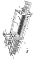
- the illustrated longitudinal cutting device is integrated in a conventional manner as a stationary longitudinal cutting station 1 in a cutting system, the z. B. upstream in aerated concrete block transport direction 2 of the cutting station 1 a fundamentfestes support frame 3 and the cutting station 1 downstream of a fundamentfestes support frame 4 has.
- the grate bars are z. B.
- a Cross cutting 7 may be arranged, which cuts the aerated concrete block transversely to its longitudinal extent ( DE 195 15 757 C1 ).
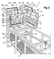
- the longitudinal cutting station 1 has a vertical standing, the cutting bed by more than one, in particular more than two cutting frame heights towering portal 15 with two lateral Grundfest, vertical supports 16, 17, the head side with a horizontal cross member 18 are braced.
- the portal 15 engages over the cutting bed, wherein the portal plane is transverse to the transport direction 2.
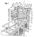
- the gantry 15 not only supports the cutting frame 8, 8a of the cutting station during cutting, but also supports two automatically operating cutting frame replacement devices according to the invention, which remove a cutting frame 8, 8a from the cutting station 1 and then re-feed another cutting frame. In this case, the removed cutting frame 8 is transported to a first parking station and then spent the parked in a second parking station cutting frame 8a to the cutting station 1.
- portalinnen pen each adjacent and extending parallel to a support 16, 17, the cross member 18 superior support columns 19, 19 a arranged.
- Each support column 19, 19a is in the foot area at a arranged in the cutting station area console element 21 and in the head area in a z. B. located in the cross member area bearing element 22, z. B. in a bearing plate, z. B. rotatable about a vertical axis held.
- B. a front longer lift arm 24, 24 a and a rear shorter abutment arm 25, 25 a.
- the length of the front lifting arm 24, 24a is for example about half the distance between the support columns 19, 19a.
- At the front free end of the lifting arm 24, 24a is a deflecting element, for example, about a horizontal, transverse to the longitudinal extension of the lifting arm 24, 24a mounted deflection roller 26, 26a rotatably arranged, over which a rope 27, 27a is deflected vertically downwards.
- the rope 27, 27a extends to connection to the deflection roller 26, 26a z.
- a support member such as a rectangular, vertically aligned, about cutting frame-sized or slightly larger or slightly smaller support frame 29, 29a, an upper cross member 30, 30a, a lower cross member 31, 31a, a front side strut 32, 32a and a rear, support-pillar side strut 33, 33a has.
- the vertical rope piece of the rope 27, 27 a is attached.
- the rear strut 33, 33a communicates with an upper support web 34, 34a and a lower support web 35, 35a with the associated support column 19, 19a in a supporting connection, wherein between the webs 34, 34a and 35, 35a and the support columns 19, 19a Guide elements (not shown) are provided, which allow a vertical raising and lowering of the support frame 29, 29 a and preferably also a pivoting of the support frame 29, 29 a about a vertical axis.
- the cutting frame 8, 8a at the cutting location for incoming to cutting block of aerated concrete facing side of the support member, for example, the support frame 29, 29a, preferably inclined slightly towards the porous concrete block to be cut and preferably limited for tilting from a vertical position to a in
- the axis of the lower cross member 10, 10a and the lower cross member 31, 31a provided horizontal respectively between the cross member 10, 10a and the cross member 31, 31a axis pivotally mounted on the support member or on the support frame 29, 29a, so that in the cutting frame. 8 , 8a upright tensioned cutting wires 13, 13a are inclined or can be variably inclined and when cutting something diagonally penetrate the porous concrete block.
- the cantilever element 23, 23 a is connected to a pivotable controllable drive device z. B. with a piston-cylinder unit 36, 36a in connection, which is supported at one end approximately in the longitudinal center region of the cross member 18 and the other end on the abutment arm 25, 25a.
- the piston-cylinder unit 36, 36a When the piston-cylinder unit 36, 36a is operated, the boom element 23, 23a is pivoted, with which the support frame 29, 29a with the integrated cutting frame 8, 8a is also pivoted.
- the cutting frame 8, 8a has an upper horizontal cross member 9, 9a, a lower horizontal cross member 10, 10a and two vertical side rails 11, 11a and 12, 12a ( Fig. 2 ), wherein between the cross beams, the cutting wires (13,13a) are stretched, which penetrate during the longitudinal cutting the porous concrete block. It may be z. B. a simple longitudinal structure cutting frame z. B. according to DE 195 15 757 C1 or z.
- Example to a longitudinal cutting frame 8, 8a, in which in the transverse bars 9, 9a and 10, 10a in the longitudinal direction of the cutting wires 13, 13a movable wire end holder (not shown) are arranged with arranged on the cutting frame 8, 8a drive means 14, 14a in itself from the EP 280 350 Bl known manner alternately relative to each other and relative to the cutting frame 8, 8a are driven.
- a cutting station 1 two z. B. same cutting frame 8, associated with 8a, which are each associated with a replacement device, with which the respective cutting frame 8, 8a can be spent for replacing the cutting location of the cutting station 1 to a respective parking location of the parking station outside the cutting site and back.
- the replaced cutting frame 8, 8a park differently, z. B. laterally next to the cutting location at about the same height.
- the cutting frames 8, 8a are arranged pivotable about a vertical axis in this embodiment of the invention.
- the cutting frames 8, 8a are parked above the cutting location according to the example described.
- This z. B. a pedestal with an accessible platform (not shown) above the cutting system provided so that the cutting frame 8, 8 a processed at the parking place, z. B. replaced the cutting wires or cutting frame can be completely replaced.
- the inventive linear cutting device of a cutting system for aerated blocks works as follows.
- An aerated concrete block is laid longitudinally extending in the transport direction on the grate bars of the support frame 3.
- the cutting wires 13 of a cutting frame 8 positioned in the cutting station 1 are moved in the direction of their longitudinal extent with the drive means 14 in an up and down movement.
- the aerated concrete block is pushed together with the grate bars with the pusher 5 and possibly supported by driven rollers or rollers on which store the grate bars through the cutting station 1, wherein the cutting wires 13 pass through the gaps between the grate bars and cut the aerated concrete block into rectangular aerated concrete body ,
- the cutting frame 8a After pivoting of the cutting frame 8, the cutting frame 8a is pivoted with its associated crane-like replacement device 19a, 24a, 25a inwards and lowered with the cable pulling device 27a, 28a in the cutting station 1 and locked. Thereafter, the cutting wires of the cutting frame 8a are started by the driving means 14a, and the next porous concrete block is pushed by the cutting frame 8a.
Landscapes
- Engineering & Computer Science (AREA)
- Structural Engineering (AREA)
- Chemical & Material Sciences (AREA)
- Ceramic Engineering (AREA)
- Mechanical Engineering (AREA)
- Devices For Post-Treatments, Processing, Supply, Discharge, And Other Processes (AREA)
- Processing Of Stones Or Stones Resemblance Materials (AREA)
Priority Applications (1)
| Application Number | Priority Date | Filing Date | Title |
|---|---|---|---|
| PL08104477T PL2018945T3 (pl) | 2007-07-25 | 2008-06-19 | Sposób i urządzenie do wzdłużnego cięcia bloku betonu komórkowego |
Applications Claiming Priority (1)
| Application Number | Priority Date | Filing Date | Title |
|---|---|---|---|
| DE102007034778A DE102007034778A1 (de) | 2007-07-25 | 2007-07-25 | Verfahren und Vorrichtung zum Längsschneiden eines Porenbetonblocks |
Publications (2)
| Publication Number | Publication Date |
|---|---|
| EP2018945A1 EP2018945A1 (de) | 2009-01-28 |
| EP2018945B1 true EP2018945B1 (de) | 2010-04-21 |
Family
ID=39940575
Family Applications (1)
| Application Number | Title | Priority Date | Filing Date |
|---|---|---|---|
| EP08104477A Active EP2018945B1 (de) | 2007-07-25 | 2008-06-19 | Verfahren und Vorrichtung zum Längsschneiden eines Porenbetonblocks |
Country Status (4)
| Country | Link |
|---|---|
| EP (1) | EP2018945B1 (pl) |
| AT (1) | ATE464988T1 (pl) |
| DE (2) | DE102007034778A1 (pl) |
| PL (1) | PL2018945T3 (pl) |
Families Citing this family (1)
| Publication number | Priority date | Publication date | Assignee | Title |
|---|---|---|---|---|
| CN107139317A (zh) * | 2017-07-14 | 2017-09-08 | 大连圣迈新建材有限公司 | 一种水泥发泡保温板切割系统 |
Family Cites Families (7)
| Publication number | Priority date | Publication date | Assignee | Title |
|---|---|---|---|---|
| DE1274947B (de) | 1963-01-16 | 1968-08-08 | Hebel Gasbetonwerke G M B H | Vorrichtung zum Schneiden von Porenbetonbloecken |
| SE301767B (pl) | 1967-02-01 | 1968-06-17 | Ytong Ab | |
| DE2216744C3 (de) | 1972-04-07 | 1975-02-20 | Grieshaber Gmbh Draht- Und Stahlverarbeitung, 7840 Muellheim | Warenträger zur Schaustellung von Waren, insbesondere Schuhen |
| DE2260744C2 (de) | 1972-12-12 | 1974-08-08 | Hebel Gasbetonwerk Gmbh, 8080 Emmering | Vorrichtung zum Schneiden von plastischen, auf einem Tisch bewegten Porenbetonblöcken in Platten verschiedener Dicke |
| DE3039005A1 (de) * | 1980-10-15 | 1982-05-13 | Georg Willy AG Maschinenfabrik, 7013 Domat | Tonstrang-schneidvorrichtung |
| NL8700271A (nl) | 1987-02-04 | 1988-09-01 | Durox Gasbeton Bv | Werkwijze en inrichting voor het snijden van gasbeton. |
| DE19515757C1 (de) | 1995-04-28 | 1996-09-05 | Ytong Ag | Vorrichtung zum Schneiden eines steifen, noch nicht gehärteten Porenbetonblocks |
-
2007
- 2007-07-25 DE DE102007034778A patent/DE102007034778A1/de not_active Withdrawn
-
2008
- 2008-06-19 DE DE502008000552T patent/DE502008000552D1/de active Active
- 2008-06-19 PL PL08104477T patent/PL2018945T3/pl unknown
- 2008-06-19 AT AT08104477T patent/ATE464988T1/de active
- 2008-06-19 EP EP08104477A patent/EP2018945B1/de active Active
Also Published As
| Publication number | Publication date |
|---|---|
| EP2018945A1 (de) | 2009-01-28 |
| ATE464988T1 (de) | 2010-05-15 |
| PL2018945T3 (pl) | 2010-09-30 |
| DE502008000552D1 (de) | 2010-06-02 |
| DE102007034778A1 (de) | 2009-01-29 |
Similar Documents
| Publication | Publication Date | Title |
|---|---|---|
| EP2025486B1 (de) | Verfahren und Vorrichtung zum Querschneiden eines Porenbetonblocks | |
| EP3268144B1 (de) | Richtmaschine und verfahren zum wechseln von richtrollenelementen | |
| DE102014019532B9 (de) | Schneidverfahren und Schneidanlage zum Quer- und Längsschneiden von schneidfesten Leichtbetonkuchen, insbesondere Poren- oder Schaumbetonkuchen, sowie Verfahren und Vorrichtung zur Herstellung von Leichtbetonformkörpern, insbesondere Poren- oder Schaumbetonformkörpern | |
| EP2467233A1 (de) | Verfahren und vorrichtung zum handhaben von brammen zum schleifen der brammen-oberflächen | |
| DE2439766A1 (de) | Stollenvortriebsmaschine | |
| DE2322542A1 (de) | Vorrichtung zur herstellung von gegossenen betonbauteilen | |
| DE2840919A1 (de) | Vorrichtung fuer das provisorische ausbauen einer strecke, sowie geeigneter ausbaurahmen | |
| EP0727385A2 (de) | Gleisgebundener Mobilkran | |
| DE2005446B2 (de) | Plattenbeladevorrichtung | |
| WO2019057230A2 (de) | Rüsten einer stanzmaschine | |
| DE1759214C3 (de) | Vorrichtung zur serienmäßigen Herstellung von einseitig offenen Raumzellen aus Stahlbeton | |
| DE3420737A1 (de) | Zusatzeinrichtung fuer hoehenverstellbare arbeitsgerueste | |
| EP0770564A2 (de) | Vorrichtung zum Lagern und Transportieren von langen Werkstücken | |
| EP2018945B1 (de) | Verfahren und Vorrichtung zum Längsschneiden eines Porenbetonblocks | |
| EP2022613B1 (de) | Stossvorrichtung in einer Porenbetonschneidanlage | |
| DE19855652C1 (de) | Verfahren und Einrichtung zum Auswechseln der Walzen von Walzgerüsten unterschiedlicher Baugröße | |
| EP1027972A2 (de) | Vorrichtung und Verfahren zum Trennen von dampfgehärteten Leichtbetonkörpern | |
| DE3608096C2 (pl) | ||
| DE4028884C2 (de) | Vorrichtung und Verfahren zum Herstellen von senkrecht stehenden Wandelementen aus Mauersteinen | |
| DE2461396A1 (de) | Ausziehvorrichtung fuer den aus- und einbau der rollen einer stranggiessmaschine | |
| DE3215743C2 (pl) | ||
| EP2986102B1 (de) | Vorrichtung zur entnahme von silage | |
| DE1531796B1 (de) | Silo fuer Schuettgueter mit einer Mittelsaeule zur Fuellung bzw. Entleerung | |
| EP0001573B1 (de) | Verfahren und Vorrichtung zum Anschweissen von Randstäben an Gitterroste | |
| EP3562726A1 (de) | Wartungskorb und verfahren zur wartung einer seilbahn |
Legal Events
| Date | Code | Title | Description |
|---|---|---|---|
| PUAI | Public reference made under article 153(3) epc to a published international application that has entered the european phase |
Free format text: ORIGINAL CODE: 0009012 |
|
| 17P | Request for examination filed |
Effective date: 20080619 |
|
| AK | Designated contracting states |
Kind code of ref document: A1 Designated state(s): AT BE BG CH CY CZ DE DK EE ES FI FR GB GR HR HU IE IS IT LI LT LU LV MC MT NL NO PL PT RO SE SI SK TR |
|
| AX | Request for extension of the european patent |
Extension state: AL BA MK RS |
|
| 17Q | First examination report despatched |
Effective date: 20090724 |
|
| AKX | Designation fees paid |
Designated state(s): AT BE BG CH CY CZ DE DK EE ES FI FR GB GR HR HU IE IS IT LI LT LU LV MC MT NL NO PL PT RO SE SI SK TR |
|
| GRAP | Despatch of communication of intention to grant a patent |
Free format text: ORIGINAL CODE: EPIDOSNIGR1 |
|
| GRAS | Grant fee paid |
Free format text: ORIGINAL CODE: EPIDOSNIGR3 |
|
| GRAA | (expected) grant |
Free format text: ORIGINAL CODE: 0009210 |
|
| AK | Designated contracting states |
Kind code of ref document: B1 Designated state(s): AT BE BG CH CY CZ DE DK EE ES FI FR GB GR HR HU IE IS IT LI LT LU LV MC MT NL NO PL PT RO SE SI SK TR |
|
| REG | Reference to a national code |
Ref country code: GB Ref legal event code: FG4D Free format text: NOT ENGLISH |
|
| REG | Reference to a national code |
Ref country code: CH Ref legal event code: EP |
|
| REG | Reference to a national code |
Ref country code: IE Ref legal event code: FG4D Free format text: LANGUAGE OF EP DOCUMENT: GERMAN |
|
| REF | Corresponds to: |
Ref document number: 502008000552 Country of ref document: DE Date of ref document: 20100602 Kind code of ref document: P |
|
| REG | Reference to a national code |
Ref country code: NL Ref legal event code: T3 |
|
| LTIE | Lt: invalidation of european patent or patent extension |
Effective date: 20100421 |
|
| REG | Reference to a national code |
Ref country code: PL Ref legal event code: T3 |
|
| REG | Reference to a national code |
Ref country code: SK Ref legal event code: T3 Ref document number: E 7535 Country of ref document: SK |
|
| PG25 | Lapsed in a contracting state [announced via postgrant information from national office to epo] |
Ref country code: NO Free format text: LAPSE BECAUSE OF FAILURE TO SUBMIT A TRANSLATION OF THE DESCRIPTION OR TO PAY THE FEE WITHIN THE PRESCRIBED TIME-LIMIT Effective date: 20100721 Ref country code: ES Free format text: LAPSE BECAUSE OF FAILURE TO SUBMIT A TRANSLATION OF THE DESCRIPTION OR TO PAY THE FEE WITHIN THE PRESCRIBED TIME-LIMIT Effective date: 20100801 Ref country code: LT Free format text: LAPSE BECAUSE OF FAILURE TO SUBMIT A TRANSLATION OF THE DESCRIPTION OR TO PAY THE FEE WITHIN THE PRESCRIBED TIME-LIMIT Effective date: 20100421 Ref country code: SE Free format text: LAPSE BECAUSE OF FAILURE TO SUBMIT A TRANSLATION OF THE DESCRIPTION OR TO PAY THE FEE WITHIN THE PRESCRIBED TIME-LIMIT Effective date: 20100421 |
|
| REG | Reference to a national code |
Ref country code: IE Ref legal event code: FD4D |
|
| PG25 | Lapsed in a contracting state [announced via postgrant information from national office to epo] |
Ref country code: LV Free format text: LAPSE BECAUSE OF FAILURE TO SUBMIT A TRANSLATION OF THE DESCRIPTION OR TO PAY THE FEE WITHIN THE PRESCRIBED TIME-LIMIT Effective date: 20100421 Ref country code: IS Free format text: LAPSE BECAUSE OF FAILURE TO SUBMIT A TRANSLATION OF THE DESCRIPTION OR TO PAY THE FEE WITHIN THE PRESCRIBED TIME-LIMIT Effective date: 20100821 Ref country code: FI Free format text: LAPSE BECAUSE OF FAILURE TO SUBMIT A TRANSLATION OF THE DESCRIPTION OR TO PAY THE FEE WITHIN THE PRESCRIBED TIME-LIMIT Effective date: 20100421 Ref country code: HR Free format text: LAPSE BECAUSE OF FAILURE TO SUBMIT A TRANSLATION OF THE DESCRIPTION OR TO PAY THE FEE WITHIN THE PRESCRIBED TIME-LIMIT Effective date: 20100421 Ref country code: SI Free format text: LAPSE BECAUSE OF FAILURE TO SUBMIT A TRANSLATION OF THE DESCRIPTION OR TO PAY THE FEE WITHIN THE PRESCRIBED TIME-LIMIT Effective date: 20100421 |
|
| PG25 | Lapsed in a contracting state [announced via postgrant information from national office to epo] |
Ref country code: CY Free format text: LAPSE BECAUSE OF FAILURE TO SUBMIT A TRANSLATION OF THE DESCRIPTION OR TO PAY THE FEE WITHIN THE PRESCRIBED TIME-LIMIT Effective date: 20100609 |
|
| PG25 | Lapsed in a contracting state [announced via postgrant information from national office to epo] |
Ref country code: EE Free format text: LAPSE BECAUSE OF FAILURE TO SUBMIT A TRANSLATION OF THE DESCRIPTION OR TO PAY THE FEE WITHIN THE PRESCRIBED TIME-LIMIT Effective date: 20100421 Ref country code: DK Free format text: LAPSE BECAUSE OF FAILURE TO SUBMIT A TRANSLATION OF THE DESCRIPTION OR TO PAY THE FEE WITHIN THE PRESCRIBED TIME-LIMIT Effective date: 20100421 Ref country code: IE Free format text: LAPSE BECAUSE OF FAILURE TO SUBMIT A TRANSLATION OF THE DESCRIPTION OR TO PAY THE FEE WITHIN THE PRESCRIBED TIME-LIMIT Effective date: 20100421 Ref country code: MC Free format text: LAPSE BECAUSE OF NON-PAYMENT OF DUE FEES Effective date: 20100630 |
|
| PLBE | No opposition filed within time limit |
Free format text: ORIGINAL CODE: 0009261 |
|
| STAA | Information on the status of an ep patent application or granted ep patent |
Free format text: STATUS: NO OPPOSITION FILED WITHIN TIME LIMIT |
|
| PG25 | Lapsed in a contracting state [announced via postgrant information from national office to epo] |
Ref country code: RO Free format text: LAPSE BECAUSE OF FAILURE TO SUBMIT A TRANSLATION OF THE DESCRIPTION OR TO PAY THE FEE WITHIN THE PRESCRIBED TIME-LIMIT Effective date: 20100421 |
|
| 26N | No opposition filed |
Effective date: 20110124 |
|
| PG25 | Lapsed in a contracting state [announced via postgrant information from national office to epo] |
Ref country code: MT Free format text: LAPSE BECAUSE OF FAILURE TO SUBMIT A TRANSLATION OF THE DESCRIPTION OR TO PAY THE FEE WITHIN THE PRESCRIBED TIME-LIMIT Effective date: 20100421 |
|
| PG25 | Lapsed in a contracting state [announced via postgrant information from national office to epo] |
Ref country code: GR Free format text: LAPSE BECAUSE OF FAILURE TO SUBMIT A TRANSLATION OF THE DESCRIPTION OR TO PAY THE FEE WITHIN THE PRESCRIBED TIME-LIMIT Effective date: 20100722 |
|
| PG25 | Lapsed in a contracting state [announced via postgrant information from national office to epo] |
Ref country code: HU Free format text: LAPSE BECAUSE OF FAILURE TO SUBMIT A TRANSLATION OF THE DESCRIPTION OR TO PAY THE FEE WITHIN THE PRESCRIBED TIME-LIMIT Effective date: 20101022 Ref country code: LU Free format text: LAPSE BECAUSE OF NON-PAYMENT OF DUE FEES Effective date: 20100619 Ref country code: PT Free format text: LAPSE BECAUSE OF FAILURE TO SUBMIT A TRANSLATION OF THE DESCRIPTION OR TO PAY THE FEE WITHIN THE PRESCRIBED TIME-LIMIT Effective date: 20100921 Ref country code: BG Free format text: LAPSE BECAUSE OF FAILURE TO SUBMIT A TRANSLATION OF THE DESCRIPTION OR TO PAY THE FEE WITHIN THE PRESCRIBED TIME-LIMIT Effective date: 20100421 |
|
| PG25 | Lapsed in a contracting state [announced via postgrant information from national office to epo] |
Ref country code: TR Free format text: LAPSE BECAUSE OF FAILURE TO SUBMIT A TRANSLATION OF THE DESCRIPTION OR TO PAY THE FEE WITHIN THE PRESCRIBED TIME-LIMIT Effective date: 20100421 |
|
| REG | Reference to a national code |
Ref country code: CH Ref legal event code: PL |
|
| REG | Reference to a national code |
Ref country code: CH Ref legal event code: PL |
|
| GBPC | Gb: european patent ceased through non-payment of renewal fee |
Effective date: 20120619 |
|
| PG25 | Lapsed in a contracting state [announced via postgrant information from national office to epo] |
Ref country code: LI Free format text: LAPSE BECAUSE OF NON-PAYMENT OF DUE FEES Effective date: 20120630 Ref country code: GB Free format text: LAPSE BECAUSE OF NON-PAYMENT OF DUE FEES Effective date: 20120619 Ref country code: CH Free format text: LAPSE BECAUSE OF NON-PAYMENT OF DUE FEES Effective date: 20120630 |
|
| PG25 | Lapsed in a contracting state [announced via postgrant information from national office to epo] |
Ref country code: BG Free format text: LAPSE BECAUSE OF FAILURE TO SUBMIT A TRANSLATION OF THE DESCRIPTION OR TO PAY THE FEE WITHIN THE PRESCRIBED TIME-LIMIT Effective date: 20100721 |
|
| REG | Reference to a national code |
Ref country code: AT Ref legal event code: MM01 Ref document number: 464988 Country of ref document: AT Kind code of ref document: T Effective date: 20130619 |
|
| PG25 | Lapsed in a contracting state [announced via postgrant information from national office to epo] |
Ref country code: AT Free format text: LAPSE BECAUSE OF NON-PAYMENT OF DUE FEES Effective date: 20130619 |
|
| REG | Reference to a national code |
Ref country code: FR Ref legal event code: PLFP Year of fee payment: 9 |
|
| REG | Reference to a national code |
Ref country code: FR Ref legal event code: PLFP Year of fee payment: 10 |
|
| REG | Reference to a national code |
Ref country code: FR Ref legal event code: PLFP Year of fee payment: 11 |
|
| PGFP | Annual fee paid to national office [announced via postgrant information from national office to epo] |
Ref country code: NL Payment date: 20250515 Year of fee payment: 18 |
|
| PGFP | Annual fee paid to national office [announced via postgrant information from national office to epo] |
Ref country code: PL Payment date: 20250416 Year of fee payment: 18 |
|
| PGFP | Annual fee paid to national office [announced via postgrant information from national office to epo] |
Ref country code: BE Payment date: 20250514 Year of fee payment: 18 Ref country code: IT Payment date: 20250513 Year of fee payment: 18 |
|
| PGFP | Annual fee paid to national office [announced via postgrant information from national office to epo] |
Ref country code: FR Payment date: 20250509 Year of fee payment: 18 |
|
| PGFP | Annual fee paid to national office [announced via postgrant information from national office to epo] |
Ref country code: SK Payment date: 20250509 Year of fee payment: 18 |
|
| PGFP | Annual fee paid to national office [announced via postgrant information from national office to epo] |
Ref country code: CZ Payment date: 20250416 Year of fee payment: 18 |
|
| PGFP | Annual fee paid to national office [announced via postgrant information from national office to epo] |
Ref country code: DE Payment date: 20250813 Year of fee payment: 18 |