EP2016338B1 - Kochfeld - Google Patents
Kochfeld Download PDFInfo
- Publication number
- EP2016338B1 EP2016338B1 EP07746432.9A EP07746432A EP2016338B1 EP 2016338 B1 EP2016338 B1 EP 2016338B1 EP 07746432 A EP07746432 A EP 07746432A EP 2016338 B1 EP2016338 B1 EP 2016338B1
- Authority
- EP
- European Patent Office
- Prior art keywords
- heater
- support spring
- main machine
- cooktop
- bracket
- Prior art date
- Legal status (The legal status is an assumption and is not a legal conclusion. Google has not performed a legal analysis and makes no representation as to the accuracy of the status listed.)
- Not-in-force
Links
Images
Classifications
-
- F—MECHANICAL ENGINEERING; LIGHTING; HEATING; WEAPONS; BLASTING
- F24—HEATING; RANGES; VENTILATING
- F24C—DOMESTIC STOVES OR RANGES ; DETAILS OF DOMESTIC STOVES OR RANGES, OF GENERAL APPLICATION
- F24C7/00—Stoves or ranges heated by electric energy
- F24C7/06—Arrangement or mounting of electric heating elements
- F24C7/067—Arrangement or mounting of electric heating elements on ranges
-
- F—MECHANICAL ENGINEERING; LIGHTING; HEATING; WEAPONS; BLASTING
- F24—HEATING; RANGES; VENTILATING
- F24C—DOMESTIC STOVES OR RANGES ; DETAILS OF DOMESTIC STOVES OR RANGES, OF GENERAL APPLICATION
- F24C7/00—Stoves or ranges heated by electric energy
- F24C7/04—Stoves or ranges heated by electric energy with heat radiated directly from the heating element
-
- H—ELECTRICITY
- H05—ELECTRIC TECHNIQUES NOT OTHERWISE PROVIDED FOR
- H05B—ELECTRIC HEATING; ELECTRIC LIGHT SOURCES NOT OTHERWISE PROVIDED FOR; CIRCUIT ARRANGEMENTS FOR ELECTRIC LIGHT SOURCES, IN GENERAL
- H05B3/00—Ohmic-resistance heating
- H05B3/68—Heating arrangements specially adapted for cooking plates or analogous hot-plates
- H05B3/74—Non-metallic plates, e.g. vitroceramic, ceramic or glassceramic hobs, also including power or control circuits
- H05B3/748—Resistive heating elements, i.e. heating elements exposed to the air, e.g. coil wire heater
Definitions
- the present invention relates to a cooktop, and more particularly, to a heater support structure of a cooktop, and a heater support spring of a cooktop that increase assembling efficiency between a main machine and a heater.
- a cooktop is a cooking appliance for delivering high heat generated from an electronic heat member to a heating portion of a top glass to cook food.
- a temperature of the heat member that is applied to the heating portion is about 500-600°C.
- the top glass is formed of tempered glass so that it is not easily destroyed by external impact.
- four or five heating portions of the top glass are provided to a predetermined position according to the standard of the cooktop. One or two of the heating portions have a greater or smaller diameter than those of other heating portions to correspond to the standard of the cooking appliance.
- An electric heater provided as a heat source to the heating portions of the top glass includes an electric heat coil installed inside a container formed of a ceramic material, and a temperature sensor attached to the container to sense heating temperature of the heat coil.
- a related art cooktop includes a main machine, a heater received inside the main machine, and a top glass provided to cover the upper surface of the main machine.
- the heater is fixed and installed on the main machine such that the upper surface of the heater contacts the lower surface of the top glass.
- a fixing member fixed on the main machine, and a separate heater support spring are coupled to each other after the heater support spring is coupled to the heater, so that the heater is fixed.
- the top glass is disposed on the heater. Since the top glass pressurizes the heater toward the upper direction of the heater, contact between the heater and the top glass is maintained.
- the heater support spring when the heater support spring is fixed to the heater using screws, it is fixed with the heater turned upside down.
- the coil installed to the heater is simply fit on the upper surface of the heater without a separate fixing element. Accordingly, when the heater support spring is fixed to the heater with the heater turned upside down, the heat coil is easily separated from the heater.
- the problem is not limited to a defect rate generated due to separation of the heat coil from the heater, but includes a problem that injures an operator's health.
- a defect rate generated due to separation of the heat coil from the heater but includes a problem that injures an operator's health.
- dusts generated while the heat coil is separated from the heater, and powder generated when the heater support spring is assembled using the screws is introduced to the operator's respiratory organ to generate respiratory ailments and skin ailments.
- DE 21 65 569 A1 describes a ceramic or glass-like hob, for an electric cooker, which has the heating elements for each of its hot zones located in a holder held against the ceramic or glass plate forming the hob.
- the holder is held by springs against the underside of the plate.
- Each spring acts on one end of a bar pivoted at its other end. The centre of each bar has a ridge that presses against the bottom of the holder.
- WO 94/24490 A1 describes a hob comprising a substantially planar member having apertures defining hotplate regions, a glass-ceramic insert being positioned in each aperture above a radiant heating element.
- the use of a moulded glass insert corresponding to a hotplate region offers several advantages over prior art hobs conventionally comprising a glass-ceramic sheet formed by a flat glass process which extends over a plurality of hotplate regions.
- DE 198 35 971 A1 describes radiant elements consisting of a carrier tray with an insulator and heat conductor in it. The carrier tray, fixed in place in a trough opposite the respective cooking spot, springs against the underside of the glass-ceramics cool top platform.
- EP 0 108 916 A2 describes a cooking-through comprising a cooking surface especially a glassceramic plate with cooking places, heating elements for the cooking places and a frame like support, which has an upper framecase, a bearing-element for the cooking-surface and an essentially vertical surrounding frame wall, on which are fixed mounting elements for parts arranged in the hollow space of the support, such as heating elements.
- DE 30 37 965 A1 describes a cooking hob with heating elements held in contact with a glass ceramic tap plate, which has each heater supported by leaf springs supported on a base plate below. Each leaf spring is S-shaped with its horizontal bottom secured to the base plate and its horizontal top secured by a screw to the heater casing.
- EP 0 211 484 A1 describes a heating unit for supporting in an opening in a hob-plate has a heating surface in the form of a glass ceramic plate surrounded by a bezel, and a housing carrying a heating element support of insulating material having a peripheral wall, the housing being secured to the bezel by a plurality of circumferentially-spaced straps forming a rigid unit, with the glass ceramic plate clamped between the bezel and the wall of the heating element support.
- An object of the present invention is to provide a cooktop that improve productivity through an increase in assembling efficiency by simplifying assembling of a heater and a main machine.
- Another object of the present invention is to provide a cooktop that can simply assembling of a heater to a main machine to improve productivity while minimizing a defect rate of the heater by seating the heater on a heater support spring after coupling the heater support spring to a fixing member when fixing the heater to the main machine.
- Still another object of the present invention is to provide a cooktop that can improve a working environment by allowing a heater to be fixed without turning the heater upside down and coupling the heater using screws.
- a cooktop having a main machine, at least one heater disposed inside the main machine, a temperature sensor for measuring a temperature of the heater, a fixing member formed in the main machine, a top glass disposed on the upper side of the main machine, and a heater support spring for supporting the heater, the cooktop including: a bracket installed in the heater, wherein the heater support spring is fixed using the fixing member, caught and supported by the bracket to seat and elastically support the heater, and limit rotation of the heater.
- a heater support tool including: a heater disposed inside a main machine; a top glass disposed on an upper side of the main machine; and at least one heater support spring supporting the heater by pushing the heater toward the top glass, wherein the heater support spring includes an installation member firmly coupled to the main machine using a predetermined coupling member, elastically supporting a lower side and a lateral side of the heater, and is installed in the heater caught and supported by the heater support spring to prevent rotation of the heater.
- a heater support spring of a cooktop that is interposed between a main machine and a heater to support the heater, and has a base fixed in the main machine, and an elastic piece extending from the base to support a lower side of the heater, the heater support spring including a side support extending perpendicularly from the base to support an outer side of the heater, wherein the side support catches a portion of the heater to prevent rotation of the heater.
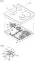
- Fig. 1 is an exploded perspective view of a cooktop according to the present invention
- Fig. 2 is an enlarged view of a cooktop of the portion A of Fig. 1
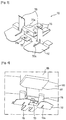
- Fig. 3 is an enlarged perspective view of a heater support spring according to the present invention.
- the cooktop 100 includes a main machine 50, heaters 60 received inside the main machine 50, a top glass 90 for covering the upper side of the main machine 50.
- the cooktop 100 heats a cooking instrument to cook food.
- the main machine 50 is formed in a box shape having an open top.
- a plurality of electric cables and devices for heat emission of the heaters 60 are installed inside the main machine 50.
- the same number of fixing members 52 as that of the heaters 60 are installed in the main machine 50.
- the plurality of fixing members 52 are arranged to correspond to positions of the heaters 60 installed inside the main machine 50, respectively.
- the fixing members 52 can be formed by cutting portions of the main machine 50.
- the cut portions include a pair of guides 53, and a bending part 54 located between the guides 53 and having a coupling hole 54a.
- a heater support spring 70 for limiting movement of the heaters 60 and stably supporting the heaters 60 is coupled to the fixing member 52.
- the heater support spring 70 includes a base 72, elastic pieces 75, and a pair of side supports 78.
- the elastic pieces 75 support the lower side of the heater 60, and can be named as a lower support.
- the side supports 78 support the lateral sides of the heater 60.
- Silts 72a into which the guides 53 of the fixing member are fitted are formed in the base 72.
- the slits 72a are provided in a pair to correspond to the pair of the guides 53.
- a fixing piece 73 plane-contacting the bending part 54 of the fixing member is formed between the slits 72a.
- a coupling hole 73a having the same measure as that of the coupling hole 54a of the fixing member is formed in the center of the fixing piece 73.
- the heater support spring 70 is coupled to the fixing member 52 in the following way.
- the guides 53 of the fixing member are fit in the slits 72a of the heater support spring, the bending part 54 of the fixing member closely contacts the fixing piece 73 of the heater support spring while they plane-contact each other.
- a screw S is coupled to pass through a pair of coupling holes 54a and 73a.
- the elastic pieces 75 for elastically supporting the lower side of the heater 60 extends from the base 72.
- the elastic pieces 75 have a shape where the central portion of portions extending from the base 72 are bent such that inner sides of the extending portions face each other.
- a screw receiving groove 75a for receiving a screw that can be installed in the lower surface of the heater 60 is formed at the front end of the elastic piece 75.
- the side supports 78 for restricting horizontal movement of the heater 60 is bent from the base 72.
- the slits 72a of the base 72 extend to the side supports 78 to allow the guides 53 to be simultaneously fitted in the side supports 78 when the guides 53 are fitted in the base 72.
- the side supports 78 are located on the same line as the front end of the elastic piece 75, and can be located both sides of the front end of the elastic piece 75. That is, the side supports 78 are located on the same line as that of the front end of the elastic piece 75 to allow the outer side of the heater 60 to maintain a closely contacting state with respect to the side supports 78 when the heater 60 is disposed on the elastic piece 75.
- the heater 60 can be formed in various shapes, description is restricted to the circle-shaped heater 60.
- a heat coil 60a is installed on the upper side of the heater 60.
- a temperature sensor 85 is installed on the periphery of the heater 60 using a bracket 87 shown in Fig. 4 .
- the bracket 87 is fixed on the periphery of the heater 60 using a screw (not shown), and the screw is received in the screw receiving groove 75a of the elastic piece.
- the top glass 90 is closely attached on the upper side of the heater 60 and coupled to the main machine 50.
- the top glass 90 is formed of a ceramic flat plate, and includes a plurality of heating portions 92 forming a predetermined arrangement.
- the top glass 92 is provided to correspond the number and arrangement of the heaters 60, and can be formed of tempered glass.
- Fig. 4 is a lower perspective view of a heater to which a heater support spring has been coupled.
- a heater support tool of a cooktop according to the present invention will be described in detail with reference to Figs. 3 and 4 .
- the heater support spring 70 is coupled to the fixing member 52 installed in the main machine 50.
- the fixing member 52 and the heater support spring 70 are coupled to each other using a screw S.
- the guides 53 are fitted in the slits 72a before the heater support spring 70 is coupled to the fixing member 52, so that an assembling process is conveniently performed as described above.
- the heater 60 is seated on the elastic piece 75 of the heater support spring 70 is seated.
- the outer peripheral surface of the heater 60 is closely attached on the inner surfaces of the side supports 78. Accordingly, horizontal movement of the heater 60 is restricted by the side supports 78.
- the bracket 87 of at least one of the heater support springs 70 is fitted between a pair of the side supports 78.
- the bracket 87 and the side supports 78 have a position relation where they are caught and supported by each other.
- the bracket 87 is designed for supporting the temperature sensor 85 as described above.
- the bracket 87 is installed between a pair of side supports 78 such that they are caught and supported by each other to prevent the heater 60 from rotating or moving against external impact or while it is carried.
- the bracket 87 is fitted between a pair of the side supports 78, so that rotation or horizontal movement of the heater 60 can be naturally limited.
- the side supports 78 contacting the periphery of the heater 60 are coupled to a pair of the guides 53, the side supports 78 stably support the periphery of the heater 60 to minimize movement of the heater 60.
- the top glass 90 is coupled to the main machine 50 while it applies force on the upper side of the heater 60 to some extent. Therefore, the heater 60 is pressurized to some extent between the top glass 90 and the main machine 50, and simultaneously, the bracket 87 is fitted between the side supports 87 of the heater support springs 70, so that movement, particularly, rotation of the heater 60 can be effectively restricted.
- the heater support springs 70 firmly support the heater 60 even when external impact is applied to the cooktop 100, or while the cooktop 100 is carried, a damage that can be generated to the heater 60 can be minimized, and durability increase can be expected.
- the bracket 87 is designed for supporting the temperature sensor.
- One bracket 87 is provided to one heater 60. Therefore, the screw receiving groove 75a may be formed in only one of the heater support springs and may not be formed in the other heater support spring.
- the screw receiving groove 75a is not limited thereto, but all of the heater support springs may be provided with the screw receiving groove 75a in order to remove difficulty in separately forming different kinds of heater support springs.
- a separate bracket 87 can be provided to other position where the temperature sensor is not provided for the purpose of supporting the heater support spring 70 as well as the temperature sensor to more firmly support the heater 60.
- the heater support springs are provided to three positions as shown in the drawing, the heater 60 can be properly supported even when the separate bracket 87 is not provided.
- the bracket 87 is provided for fixing the temperature sensor because a separate part is not consumed, the bracket 87 is not limited thereto. That is, the temperature sensor can be fixed for itself, and another bracket can be separately further provided for preventing rotation and movement of the heater support spring. Further, the bracket can be provided in a predetermined shape integrally on the outer surface of the heater, and can be separately provided on the outer surface of the heater.
- the plurality of heater support springs are provided, other portion can be supported by other type of a heater support spring, and at least one portion can be supported by the heater support spring according to the present invention.
- the heater support spring can be installed not only to allow the upper side of the main machine to approach the top glass completely sealing the upper side of the main machine, but also to support the heater with a predetermined portion of the top glass opened.
- the screw coupling process is simply performed one time while the heater is coupled to the main machine, a defective heater is not manufactured, and productivity can be improved through an increase in assembling efficiency.
- the heater can be fixed without turning the heater upside down and coupling screws, which can improve a working environment.
- the heater is not rotated and can be stably supported by the heater support spring.
Landscapes
- Engineering & Computer Science (AREA)
- Chemical & Material Sciences (AREA)
- Combustion & Propulsion (AREA)
- Mechanical Engineering (AREA)
- General Engineering & Computer Science (AREA)
- Ceramic Engineering (AREA)
- Electric Stoves And Ranges (AREA)
- Baking, Grill, Roasting (AREA)
- Induction Heating Cooking Devices (AREA)
- Resistance Heating (AREA)
- Control Of Resistance Heating (AREA)
Claims (4)
- Herdplatte, die eine Hauptmaschine (50), wenigstens ein Heizelement (60), das in der Hauptmaschine (50) angeordnet ist, einen Temperatursensor (85) zum Messen einer Temperatur des Heizelements (60), ein Befestigungselement (52), das in der Hauptmaschine ausgebildet ist, ein oberes Glas (90), das auf der Oberseite der Hauptmaschine (50) angeordnet ist, und eine Heizelement-Haltefeder (70) zum Halten des Heizelements (60) aufweist, wobei die Herdplatte (100) Folgendes umfasst:eine Halterung (87), die in das Heizelement (60) eingebaut ist, wobei die Heizelement-Haltefeder (70) unter Verwendung des Befestigungselements (52) befestigt ist, wobei die Heizelement-Haltefeder (70) durch die Halterung (87) erfasst und gehalten wird, wobei das Heizelement (60) auf der Heizelement-Haltefeder (70) sitzt und durch diese elastisch gehalten wird und wobei die Heizelement-Haltefeder (70) eine Drehung des Heizelements (60) begrenzt,dadurch gekennzeichnet, dass die Halterung (87) zwischen einem Paar Seitenhalterungen (78), die an der Heizelement-Haltefeder (70) ausgebildet sind, angeordnet ist, um eine Drehung des Heizelements (60) einzuschränken.
- Herdplatte nach Anspruch 1, wobei das Befestigungselement (52) Folgendes umfasst:ein Paar Führungen (53), in die die Heizelement-Haltefeder (70) eingepasst ist; undein Biegebauteil (54), das zwischen den Führungen (53) angeordnet ist und ein Schraubenverbindungsloch (54a) aufweist.
- Herdplatte nach Anspruch 1 oder 2, wobei die Heizelement-Haltefeder (70) Folgendes umfasst:eine Basis (72), die mit Schlitzen (72a) zum Aufnehmen eines Paars Führungen (53) versehen ist und an einem mittleren Abschnitt mit einem Befestigungsbauteil für einen Flächenkontakt des Biegebauteils des Befestigungselements vorgesehen ist;ein elastisches Bauteil (75), das sich von der Basis (72) erstreckt, um eine untere Seite des Heizelements (60) elastisch zu halten; undein Paar Seitenhalterungen (78), die von der Basis (72) senkrecht weggebogen sind, um die Führungen (53) aufzunehmen und gleichzeitig eine horizontale Bewegung des Heizelements (60) einzuschränken.
- Herdplatte nach einem der Ansprüche 1 bis 3, wobei die Halterung (87) vorgesehen ist, um den Temperatursensor (85) an dem Heizelement (60) zu installieren.
Applications Claiming Priority (2)
| Application Number | Priority Date | Filing Date | Title |
|---|---|---|---|
| KR1020060042442A KR100771628B1 (ko) | 2006-05-11 | 2006-05-11 | 전기레인지 |
| PCT/KR2007/002279 WO2007133003A1 (en) | 2006-05-11 | 2007-05-09 | Cooktop, heater support device of cooktop, and heater support spring of cooktop |
Publications (3)
| Publication Number | Publication Date |
|---|---|
| EP2016338A1 EP2016338A1 (de) | 2009-01-21 |
| EP2016338A4 EP2016338A4 (de) | 2015-04-08 |
| EP2016338B1 true EP2016338B1 (de) | 2016-07-20 |
Family
ID=38694072
Family Applications (1)
| Application Number | Title | Priority Date | Filing Date |
|---|---|---|---|
| EP07746432.9A Not-in-force EP2016338B1 (de) | 2006-05-11 | 2007-05-09 | Kochfeld |
Country Status (6)
| Country | Link |
|---|---|
| US (1) | US20090294432A1 (de) |
| EP (1) | EP2016338B1 (de) |
| KR (1) | KR100771628B1 (de) |
| AU (1) | AU2007250708B2 (de) |
| MX (1) | MX2008014352A (de) |
| WO (1) | WO2007133003A1 (de) |
Families Citing this family (10)
| Publication number | Priority date | Publication date | Assignee | Title |
|---|---|---|---|---|
| KR100955274B1 (ko) | 2009-02-27 | 2010-04-30 | 제이씨텍(주) | 전기레인지 및 그 제어방법 |
| KR101238105B1 (ko) | 2011-07-21 | 2013-02-27 | 엘지전자 주식회사 | 전기 오븐 |
| EP2784396B1 (de) | 2013-03-27 | 2017-04-19 | Whirlpool Corporation | Kochfeld |
| ES2533243B1 (es) * | 2013-10-03 | 2016-01-14 | Bsh Electrodomésticos España, S.A. | Dispositivo de campo de cocción |
| US9521708B2 (en) | 2014-01-10 | 2016-12-13 | Haier Us Appliance Solutions, Inc. | Oven range appliance |
| EP2957836B1 (de) * | 2014-06-19 | 2018-11-28 | Guangdong Midea Kitchen Appliances | Befestigungselement, kochfeld und kochherd damit |
| ES2673704B1 (es) * | 2016-12-23 | 2019-05-14 | Bsh Electrodomesticos Espana Sa | Dispositivo de aparato de coccion |
| KR102426314B1 (ko) * | 2018-03-06 | 2022-07-28 | 에스케이매직 주식회사 | 전기레인지 |
| KR200490893Y1 (ko) * | 2018-03-30 | 2020-02-11 | 이우석 | 인덕션 전기 레인지 |
| DE102020214794A1 (de) * | 2020-11-25 | 2022-05-25 | E.G.O. Elektro-Gerätebau GmbH | Kochfeld und Verfahren zur Montage eines solchen Kochfelds |
Family Cites Families (74)
| Publication number | Priority date | Publication date | Assignee | Title |
|---|---|---|---|---|
| US843775A (en) * | 1905-07-31 | 1907-02-12 | Samuel W Taliaferro | Electric heater. |
| US1189590A (en) * | 1912-10-26 | 1916-07-04 | Packard Motor Car Co | Motor-vehicle. |
| US1180417A (en) * | 1914-10-22 | 1916-04-25 | William H Miner | Leaf-spring. |
| US1178860A (en) * | 1915-09-28 | 1916-04-11 | Becker C Knudsen | Antirattling structure for vehicles and the like. |
| US2361285A (en) * | 1941-02-17 | 1944-10-24 | Chicago Electric Mfg Co | Electric cooking appliance |
| US2682602A (en) * | 1950-09-05 | 1954-06-29 | Knapp Monarch Co | Thermostat for cookers |
| US2712055A (en) * | 1952-05-05 | 1955-06-28 | James R Campbell | Electric heating system |
| US2804531A (en) * | 1952-10-30 | 1957-08-27 | Nash Kelvinator Corp | Range |
| US2808497A (en) * | 1955-09-08 | 1957-10-01 | Gen Motors Corp | Domestic appliance |
| US2952764A (en) * | 1957-05-29 | 1960-09-13 | Tokyo Shibaura Electric Co | Method and apparatus for automatically boiling rice |
| US3097285A (en) * | 1960-09-30 | 1963-07-09 | Warren Page | Thermostat-timer device |
| US3108531A (en) * | 1962-05-14 | 1963-10-29 | Sunbeam Corp | Electric heating and cooking device |
| US3272111A (en) * | 1963-05-17 | 1966-09-13 | Charles J Cretors | Corn popper |
| US3348024A (en) * | 1964-10-08 | 1967-10-17 | Gen Electric | Toast temperature detector |
| US3393295A (en) * | 1964-12-29 | 1968-07-16 | Sunbeam Corp | Cooking device with proportioning control |
| US3395264A (en) * | 1965-05-03 | 1968-07-30 | Sperry Rand Corp | Marking apparatus |
| US3390251A (en) * | 1965-10-22 | 1968-06-25 | Joshua D. Lowenfish | Heating device |
| US3418917A (en) * | 1966-05-23 | 1968-12-31 | Matsushita Electric Industrial Co Ltd | Semi-automatic pop-up toaster |
| US3371594A (en) * | 1966-07-26 | 1968-03-05 | Sunbeam Corp | Bread toaster |
| US3529534A (en) * | 1969-04-03 | 1970-09-22 | Gen Electric | Electric toaster with heat up cool down bimetal timer |
| US3622754A (en) * | 1970-07-24 | 1971-11-23 | Gen Electric | Glass plate surface heating unit with even temperature distribution |
| DE2165569C3 (de) | 1971-12-30 | 1986-05-28 | E.G.O. Elektro-Geräte Blanc u. Fischer, 7519 Oberderdingen | Elektrokochgerät mit einer oberen Platte aus hochwärmebeständigem glasartigem bzw. keramischem Material |
| US4195560A (en) * | 1977-07-11 | 1980-04-01 | Sunbeam Corporation | Electric crepe maker |
| DE3037965C2 (de) | 1980-10-08 | 1982-10-28 | Blanc Gmbh & Co, 7519 Oberderdingen | Kochmulde mit einer die Kochfläche bildenden Glaskeramikplatte |
| DE8229638U1 (de) * | 1982-10-22 | 1982-12-23 | E.G.O. Elektro-Geräte Blanc u. Fischer, 7519 Oberderdingen | Vorrichtung zur befestigung eines elektrischen heizkoerpers |
| DE3242026C2 (de) * | 1982-11-12 | 1985-08-14 | Bosch-Siemens Hausgeräte GmbH, 7000 Stuttgart | Kochmulde mit einem rahmenartigen Träger |
| AT386714B (de) * | 1983-07-07 | 1988-10-10 | Electrovac | Vorrichtung zur heissanzeige und zur regelung bzw. begrenzung der temperatur von strahlungsbzw. kontaktheizkoerpern von elektrischen kochgeraeten |
| DE8329498U1 (de) * | 1983-10-12 | 1984-01-26 | Bosch-Siemens Hausgeräte GmbH, 7000 Stuttgart | Kochmulde |
| US4527707A (en) * | 1984-04-16 | 1985-07-09 | Heymann Mark S | Devices for securing a debris holding tray to a glass or dish rack |
| DE3441281A1 (de) * | 1984-11-12 | 1986-05-22 | Bosch-Siemens Hausgeräte GmbH, 7000 Stuttgart | Kochmulde |
| GB8514785D0 (en) * | 1985-06-11 | 1985-07-10 | Micropore International Ltd | Infra-red heaters |
| GB8517401D0 (en) | 1985-07-10 | 1985-08-14 | Redring Electric Ltd | Electric hobs |
| EP0234373A3 (de) * | 1986-02-26 | 1988-03-02 | E.G.O. Elektro-Geräte Blanc u. Fischer | Kocheinheit mit Strahlheizkörper |
| CA1333194C (en) * | 1988-06-14 | 1994-11-22 | Taisuke Morino | High-frequency heating apparatus |
| JPH0369856U (de) * | 1989-11-11 | 1991-07-11 | ||
| US5106586A (en) * | 1990-05-23 | 1992-04-21 | Eastman Kodak Company | J-shaped spring used in incubator |
| GB2277145B (en) | 1993-04-13 | 1997-08-27 | Redring Electric Ltd | A hob |
| US5413032A (en) * | 1994-08-18 | 1995-05-09 | The Middleby Corporation | Restaurant type griddle with modular construction and which is load sensitive |
| DE19527823A1 (de) * | 1995-07-29 | 1997-01-30 | Ego Elektro Blanc & Fischer | Kochmuldeneinheit mit mehreren unterhalb einer Platte angeordneten Kochstellen |
| DE19604306C2 (de) * | 1996-02-07 | 2000-05-11 | Ako Werke Gmbh & Co | Strahlungsheizkörper |
| DE19746844C1 (de) * | 1997-10-23 | 1998-12-03 | Schott Glas | Anordnung eines keramischen Heizelementes als Kochzone in einer Aussparung einer Kochfläche |
| KR19990017318U (ko) * | 1997-10-31 | 1999-05-25 | 전주범 | 전기 조리기의 히터 고정구조 |
| AT405117B (de) * | 1997-11-07 | 1999-05-25 | Electrovac | Temperaturbegrenzer mit sensorelektrode |
| DE19835971C2 (de) | 1998-08-08 | 2001-10-18 | Aeg Hausgeraete Gmbh | Halteanordnung für Strahlungsheizkörper bei einem Glaskeramik-Kochfeld |
| KR100365593B1 (ko) * | 1999-12-31 | 2002-12-26 | 주식회사에이테크엔지니어링 | 숯불조리기 |
| DE10006954A1 (de) * | 2000-02-16 | 2001-10-11 | Bsh Bosch Siemens Hausgeraete | Kochfeld mit Temperaturfühler |
| DE10006974A1 (de) * | 2000-02-16 | 2001-08-23 | Bsh Bosch Siemens Hausgeraete | Kochfeld mit Temperaturfühler |
| DE10006956A1 (de) * | 2000-02-16 | 2001-08-23 | Bsh Bosch Siemens Hausgeraete | Kochfeld mit Temperaturfühler |
| US6457804B1 (en) * | 2000-04-25 | 2002-10-01 | Hewlett-Packard Company | Spring for latching a print cartridge in a carriage |
| JP3516392B2 (ja) * | 2000-06-16 | 2004-04-05 | イビデン株式会社 | 半導体製造・検査装置用ホットプレート |
| US6464215B1 (en) * | 2000-09-25 | 2002-10-15 | Aer Energy Resources, Inc. | Vibration damping mount for a metal-air battery or the like |
| JP2002318064A (ja) * | 2001-02-09 | 2002-10-31 | Mando Climate Control Corp | 漬物貯蔵庫のドア用ヒンジ組立体 |
| DE10250317B4 (de) * | 2002-10-29 | 2004-10-28 | Schott Glas | Glas- oder Glaskeramikplatte mit einer elektrischen Heizeinheit |
| US6883679B2 (en) * | 2002-10-30 | 2005-04-26 | L. L. Culmat L.P. | Snap-insert hole closing plug |
| ES2421432T3 (es) * | 2002-11-15 | 2013-09-02 | Tyco Electronics Amp Gmbh | Elemento de contacto con lengüeta de resorte |
| FR2848955B1 (fr) * | 2002-12-20 | 2005-02-18 | Journee Paul | Connecteur reliant un bras d'essuie-glace a un balai d'essuyage, qui comporte un corps et une languette de blocage dont une de ses extremites est reliee au corps par un film de matiere secable |
| US6883513B2 (en) * | 2003-09-05 | 2005-04-26 | Premark Feg L.L.C. | Rack oven and associated rack carrier |
| TW588145B (en) * | 2003-10-03 | 2004-05-21 | Asustek Comp Inc | Easily assembled device and connecting structure thereof |
| EP1523226B1 (de) * | 2003-10-07 | 2014-12-10 | Behr France Rouffach SAS | Heizungsanordnung mit PTC-Element, insbesondere für ein Kraftfahrzeug |
| US7204000B2 (en) * | 2003-10-13 | 2007-04-17 | Newfrey Llc | Fastener for fixed rib applications |
| DE102004023788A1 (de) | 2004-05-07 | 2005-12-01 | E.G.O. Elektro-Gerätebau GmbH | Kochfeld, Heizeinrichtung für ein Kochfeld und Verfahren zur Montage einer Heizeinrichtung an ein Kochfeld |
| US7135658B2 (en) * | 2004-06-08 | 2006-11-14 | Paul J Rael | Magnetic safety feature for cookware and cooking stoves |
| ES1057791Y (es) * | 2004-06-14 | 2005-01-01 | Eika S Coop | Calefactor radiante en una encimera de coccion, con un interruptor termico. |
| US7307246B2 (en) * | 2004-06-28 | 2007-12-11 | General Electric Company | System and method of detecting temperature of a cooking utensil over a radiant cooktop |
| KR100658839B1 (ko) * | 2004-08-12 | 2006-12-15 | 엘지전자 주식회사 | 가열부재의 설치구조 |
| KR100739604B1 (ko) * | 2004-09-20 | 2007-07-16 | 엘지전자 주식회사 | 전기레인지용 인덕션 히팅 모듈의 설치 구조 |
| GB0426467D0 (en) * | 2004-12-02 | 2005-01-05 | Ceramaspeed Ltd | Apparatus for detecting abnormal temperature rise associated with a cooking arrangement |
| US20060117524A1 (en) * | 2004-12-07 | 2006-06-08 | Li-Lan Yan | Structure of a shock absorbing caster |
| US7487718B2 (en) * | 2004-12-30 | 2009-02-10 | Solbern Llc | Platform for conveyor system |
| GB0502390D0 (en) * | 2005-02-05 | 2005-03-16 | Ceramaspeed Ltd | Electrical heating arrangement |
| KR100678669B1 (ko) * | 2005-06-28 | 2007-02-05 | 삼성전자주식회사 | 전기 쿡탑 |
| KR100889078B1 (ko) * | 2007-04-24 | 2009-03-17 | 엘지전자 주식회사 | 가열조리기기 |
| EP2144007B1 (de) * | 2008-07-09 | 2015-09-02 | Electrolux Home Products Corporation N.V. | Stützträger zum Tragen einer strahlenden Wärmevorrichtung auf einer Bodenplatte eines Kochfelds |
| ES2627614T3 (es) * | 2010-11-12 | 2017-07-28 | Arçelik Anonim Sirketi | Dispositivo de cocción |
-
2006
- 2006-05-11 KR KR1020060042442A patent/KR100771628B1/ko active Active
-
2007
- 2007-05-09 US US12/300,103 patent/US20090294432A1/en not_active Abandoned
- 2007-05-09 MX MX2008014352A patent/MX2008014352A/es active IP Right Grant
- 2007-05-09 AU AU2007250708A patent/AU2007250708B2/en not_active Ceased
- 2007-05-09 EP EP07746432.9A patent/EP2016338B1/de not_active Not-in-force
- 2007-05-09 WO PCT/KR2007/002279 patent/WO2007133003A1/en not_active Ceased
Also Published As
| Publication number | Publication date |
|---|---|
| AU2007250708B2 (en) | 2010-05-20 |
| EP2016338A1 (de) | 2009-01-21 |
| WO2007133003A1 (en) | 2007-11-22 |
| AU2007250708A1 (en) | 2007-11-22 |
| MX2008014352A (es) | 2008-11-24 |
| US20090294432A1 (en) | 2009-12-03 |
| KR100771628B1 (ko) | 2007-10-31 |
| EP2016338A4 (de) | 2015-04-08 |
Similar Documents
| Publication | Publication Date | Title |
|---|---|---|
| EP2016338B1 (de) | Kochfeld | |
| US20160057815A1 (en) | Induction cooking appliance and method for assembling same | |
| US5847364A (en) | Radiant heater support system | |
| EP1475998A1 (de) | Elektrischer Heizungsaufbau | |
| EP1445542B1 (de) | Kochvorrichtung | |
| KR101238105B1 (ko) | 전기 오븐 | |
| WO2009083389A1 (en) | A cooktop | |
| WO2017020964A1 (en) | Improved mounting assembly for use in a cooking appliance | |
| KR101620100B1 (ko) | 빌트인 타입 조리기기 | |
| US11519608B2 (en) | Embossed feature for cooktop assembly | |
| CN212234118U (zh) | 烹饪器具 | |
| JP2019180532A (ja) | 調理器 | |
| CN220109572U (zh) | 盖体及烹饪器具 | |
| KR20180025755A (ko) | 조작유닛 및 이것이 설치된 가전기기 | |
| CN211432215U (zh) | 烹饪器具及控制板组件 | |
| US20240230106A1 (en) | Removable bracket assembly for an oven appliance manifold | |
| US20250027657A1 (en) | Alignment features for a panel assembly of an appliance | |
| EP3989679B1 (de) | Ein induktionsheizgerät | |
| CN219283406U (zh) | 加热结构及烹饪器具 | |
| CN222640316U (zh) | 盖体和烹饪器具 | |
| CN219895343U (zh) | 煲体和烹饪器具 | |
| CN209202789U (zh) | 一种烹饪器具 | |
| JP5474380B2 (ja) | 調理器のグリル装置 | |
| KR100425134B1 (ko) | 유도가열 전기밥솥의 자력선 차폐판 고정구조 | |
| KR100662355B1 (ko) | 전기 레인지 |
Legal Events
| Date | Code | Title | Description |
|---|---|---|---|
| PUAI | Public reference made under article 153(3) epc to a published international application that has entered the european phase |
Free format text: ORIGINAL CODE: 0009012 |
|
| 17P | Request for examination filed |
Effective date: 20081030 |
|
| AK | Designated contracting states |
Kind code of ref document: A1 Designated state(s): AT BE BG CH CY CZ DE DK EE ES FI FR GB GR HU IE IS IT LI LT LU LV MC MT NL PL PT RO SE SI SK TR |
|
| AX | Request for extension of the european patent |
Extension state: AL BA HR MK RS |
|
| RBV | Designated contracting states (corrected) |
Designated state(s): DE FR GB IT SE |
|
| DAX | Request for extension of the european patent (deleted) | ||
| RIC1 | Information provided on ipc code assigned before grant |
Ipc: H05B 3/74 20060101ALI20150225BHEP Ipc: F24C 7/06 20060101AFI20150225BHEP |
|
| RA4 | Supplementary search report drawn up and despatched (corrected) |
Effective date: 20150310 |
|
| RIC1 | Information provided on ipc code assigned before grant |
Ipc: F24C 7/06 20060101AFI20150304BHEP Ipc: H05B 3/74 20060101ALI20150304BHEP |
|
| RIC1 | Information provided on ipc code assigned before grant |
Ipc: F24C 7/06 20060101AFI20151204BHEP Ipc: H05B 3/74 20060101ALI20151204BHEP |
|
| GRAP | Despatch of communication of intention to grant a patent |
Free format text: ORIGINAL CODE: EPIDOSNIGR1 |
|
| INTG | Intention to grant announced |
Effective date: 20160202 |
|
| RAP1 | Party data changed (applicant data changed or rights of an application transferred) |
Owner name: LG ELECTRONICS INC. |
|
| GRAS | Grant fee paid |
Free format text: ORIGINAL CODE: EPIDOSNIGR3 |
|
| GRAA | (expected) grant |
Free format text: ORIGINAL CODE: 0009210 |
|
| AK | Designated contracting states |
Kind code of ref document: B1 Designated state(s): DE FR GB IT SE |
|
| REG | Reference to a national code |
Ref country code: GB Ref legal event code: FG4D |
|
| REG | Reference to a national code |
Ref country code: DE Ref legal event code: R096 Ref document number: 602007047081 Country of ref document: DE |
|
| REG | Reference to a national code |
Ref country code: SE Ref legal event code: TRGR |
|
| REG | Reference to a national code |
Ref country code: DE Ref legal event code: R097 Ref document number: 602007047081 Country of ref document: DE |
|
| PLBE | No opposition filed within time limit |
Free format text: ORIGINAL CODE: 0009261 |
|
| STAA | Information on the status of an ep patent application or granted ep patent |
Free format text: STATUS: NO OPPOSITION FILED WITHIN TIME LIMIT |
|
| 26N | No opposition filed |
Effective date: 20170421 |
|
| REG | Reference to a national code |
Ref country code: DE Ref legal event code: R119 Ref document number: 602007047081 Country of ref document: DE |
|
| REG | Reference to a national code |
Ref country code: SE Ref legal event code: EUG |
|
| GBPC | Gb: european patent ceased through non-payment of renewal fee |
Effective date: 20170509 |
|
| PG25 | Lapsed in a contracting state [announced via postgrant information from national office to epo] |
Ref country code: SE Free format text: LAPSE BECAUSE OF NON-PAYMENT OF DUE FEES Effective date: 20170510 |
|
| REG | Reference to a national code |
Ref country code: FR Ref legal event code: ST Effective date: 20180131 |
|
| PG25 | Lapsed in a contracting state [announced via postgrant information from national office to epo] |
Ref country code: DE Free format text: LAPSE BECAUSE OF NON-PAYMENT OF DUE FEES Effective date: 20171201 Ref country code: GB Free format text: LAPSE BECAUSE OF NON-PAYMENT OF DUE FEES Effective date: 20170509 |
|
| PG25 | Lapsed in a contracting state [announced via postgrant information from national office to epo] |
Ref country code: IT Free format text: LAPSE BECAUSE OF NON-PAYMENT OF DUE FEES Effective date: 20170509 Ref country code: FR Free format text: LAPSE BECAUSE OF NON-PAYMENT OF DUE FEES Effective date: 20170531 |