EP2012281A2 - Vorrichtung zur Warenausgabe - Google Patents
Vorrichtung zur Warenausgabe Download PDFInfo
- Publication number
- EP2012281A2 EP2012281A2 EP08156361A EP08156361A EP2012281A2 EP 2012281 A2 EP2012281 A2 EP 2012281A2 EP 08156361 A EP08156361 A EP 08156361A EP 08156361 A EP08156361 A EP 08156361A EP 2012281 A2 EP2012281 A2 EP 2012281A2
- Authority
- EP
- European Patent Office
- Prior art keywords
- commodity
- bucket
- carrying
- main unit
- width direction
- Prior art date
- Legal status (The legal status is an assumption and is not a legal conclusion. Google has not performed a legal analysis and makes no representation as to the accuracy of the status listed.)
- Granted
Links
Images






Classifications
-
- G—PHYSICS
- G07—CHECKING-DEVICES
- G07F—COIN-FREED OR LIKE APPARATUS
- G07F11/00—Coin-freed apparatus for dispensing, or the like, discrete articles
- G07F11/02—Coin-freed apparatus for dispensing, or the like, discrete articles from non-movable magazines
- G07F11/38—Coin-freed apparatus for dispensing, or the like, discrete articles from non-movable magazines in which the magazines are horizontal
- G07F11/42—Coin-freed apparatus for dispensing, or the like, discrete articles from non-movable magazines in which the magazines are horizontal the articles being delivered by motor-driven means
-
- G—PHYSICS
- G07—CHECKING-DEVICES
- G07F—COIN-FREED OR LIKE APPARATUS
- G07F11/00—Coin-freed apparatus for dispensing, or the like, discrete articles
- G07F11/02—Coin-freed apparatus for dispensing, or the like, discrete articles from non-movable magazines
- G07F11/04—Coin-freed apparatus for dispensing, or the like, discrete articles from non-movable magazines in which magazines the articles are stored one vertically above the other
- G07F11/16—Delivery means
- G07F11/163—Delivery means characterised by blocking access to the output bins
-
- G—PHYSICS
- G07—CHECKING-DEVICES
- G07F—COIN-FREED OR LIKE APPARATUS
- G07F11/00—Coin-freed apparatus for dispensing, or the like, discrete articles
- G07F11/02—Coin-freed apparatus for dispensing, or the like, discrete articles from non-movable magazines
- G07F11/04—Coin-freed apparatus for dispensing, or the like, discrete articles from non-movable magazines in which magazines the articles are stored one vertically above the other
- G07F11/16—Delivery means
- G07F11/165—Delivery means using xyz-picker or multi-dimensional article picking arrangements
- G07F11/1653—Delivery means using xyz-picker or multi-dimensional article picking arrangements the picking arrangements being collecting buckets
-
- G—PHYSICS
- G07—CHECKING-DEVICES
- G07F—COIN-FREED OR LIKE APPARATUS
- G07F11/00—Coin-freed apparatus for dispensing, or the like, discrete articles
- G07F11/02—Coin-freed apparatus for dispensing, or the like, discrete articles from non-movable magazines
- G07F11/28—Coin-freed apparatus for dispensing, or the like, discrete articles from non-movable magazines in which the magazines are inclined
- G07F11/30—Coin-freed apparatus for dispensing, or the like, discrete articles from non-movable magazines in which the magazines are inclined two or more magazines having independent delivery
Definitions
- the present invention relates to a commodity carrying out device that is capable of carrying out a commodity that is stored in a commodity storage column to a predetermined commodity carrying out position.
- a device that includes a plurality of commodity storage columns that are aligned with respect to each other in a vertical direction and a width direction for storing commodities in a condition in which the commodities are arranged in the front-to-rear direction, a bucket for receiving a commodity that is stored in a selected commodity storage column, and a bucket moving mechanism for moving the bucket to the front side of an arbitrary commodity storage column and moving the bucket that receives a commodity to a predetermined commodity carrying out position.
- a commodity stored in a commodity storage column is received in the bucket in a state in which the commodity has the same posture as when the commodity is stored in the commodity storage column and the bucket is then moved to the predetermined commodity carrying out position. Consequently, in a case in which a commodity that has a vertically long shape is received in a bucket in an upright state, when the bucket is moved in the width direction towards the predetermined commodity carrying out position a situation can arise in which the commodity becomes unstable inside the bucket, such as when the commodity topples over to the side that is opposite the predetermined commodity carrying out position. There is thus a risk that a carrying-out failure, such as the commodity dropping down from the bucket, will occur.
- the present invention comprises: a plurality of commodity storage columns aligned in a vertical direction and a width direction with respect to each other for storing commodities arranged in a front-to-rear direction; a bucket for receiving a commodity to be carried out, and in which movement of the commodity in a direction other than a direction towards a surface side from which the commodity is taken in and put out is restricted; a bucket moving mechanism for moving the bucket to a front side of an arbitrary commodity storage column and moving the bucket that receives the commodity to a predetermined commodity carrying out position; and a bucket rotating mechanism for rotating the bucket so that a surface at which the commodity is taken in and put out of the bucket faces the commodity storage column side and the predetermined commodity carrying out position side.
- the present invention comprises: a plurality of commodity storage columns aligned in a vertical direction and a width direction with respect to each other for storing commodities arranged in a front-to-rear direction; a bucket for receiving a commodity to be carried out; a bucket moving mechanism for moving the bucket to a front side of an arbitrary commodity storage column and moving the bucket that receives the commodity to a predetermined commodity carrying out position; and a commodity retention mechanism for retaining the commodity in an inclined posture when moving the bucket that receives the commodity to a predetermined commodity carrying out position.
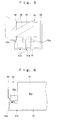
- the automatic vending machine main unit 10 is provided with a commodity storage chamber 12 for storing commodities A for sale and an equipment storage chamber 13 for storing equipment relating to selling operations. This is achieved by partitioning the inside of the automatic vending machine main unit 10 in the width direction with a heat insulating partition wall 11. The interior surface of the commodity storage chamber 12 is covered with a heat insulating material. At the lower part of the equipment storage chamber 13 is provided a commodity outlet portion 14 to which a commodity A to be sold is carried. An opening 15 that connects the commodity outlet portion 14 and the commodity storage chamber 12 is provided in the partition wall 11.
- the external door 20 is rotatably supported at one end side in the width direction of the automatic vending machine main unit 10 and is arranged to open and close the front of the commodity storage chamber 12.
- the external door 20 comprises a transparent plate 21 comprising glass or a synthetic resin or the like and a frame member 22 provided around the perimeter of the transparent plate 21.
- the interior of the commodity storage chamber 12 can be visually recognized from outside the external door 20.
- each of the vertically aligned shelves 40 are slightly greater than the height dimensions of a commodity A to be stored. This prevents erroneous storage of a commodity A that has large height dimensions that are different to the height dimensions of a commodity A that is intended to be stored.
- Each shelf 40 is formed so that the dimensions thereof in the front-to-rear direction are smaller than the dimensions in the front-to-rear direction of the commodity storage column 50. Further, to secure an operating space for receiving a commodity A into the bucket unit 60 from the commodity storage column 50, the front end of each shelf 40 is positioned further to the rear side than the front end of the commodity storage column 50.
- Each commodity storage column 50 is provided with a commodity passage 50a extending in the front-to-rear direction that is formed by a base plate 51 and a side plate 52.
- Vertically long commodities A such as canned beverages, bottled beverages, or PET bottles can be stored in the commodity passage 50a in a condition in which they are aligned in the front-to-rear direction.
- a commodity locking portion 51a that is formed to extend vertically is provided for restricting movement of a commodity A in the frontward direction.
- a notch portion 51b that enables movement of a fork member, described later, of the bucket unit 60 in the vertical direction.
- An ejecting plate 53 which is movable in the front-to-rear direction and which is urged frontward by an unshown urging member such as a power spring is disposed in the commodity passage 50a.
- an unshown urging member such as a power spring
- the ejecting plate 53 is provided with a notch portion 53a to enable movement in the vertical direction of a fork member, described later, of the bucket unit 60 when the ejecting plate 53 is positioned at the front end side of the commodity passage 50a.
- a gate plate 54 that opens and closes the front end side of the commodity passage 50a is connected in a vertically rotatable condition to the front end side of the side plate 52.
- the gate plate 54 is arranged so as to block off the commodity passage 50a in a posture in which it extends diagonally upward from the side plate 52.
- the gate plate 54 is urged in a direction that blocks off the commodity passage 50a by an urging member such as a coiled spring.
- the gate plate 54 is arranged to open the commodity passage 50a by rotating upward against the urging force of the urging member through contact of a gate release portion, described later, provided on the bucket unit 60 side against the bottom surface of the gate plate 54.
- a guide portion 52a for guiding the gate release portion in the front-to-rear direction is also provided on the commodity passage 50a side of the side plate 52 on which the gate plate 54 is supported.
- the unit base 61 has an electric motor 61a as a motive power that moves the bucket base 62 in the front-to-rear direction and also rotates the bucket 64, a guide groove 61b for guiding the bucket base 62 in the front-to-rear direction, a protrusion 61c that imparts a force that rotates the rotating member 63 to the commodity outlet portion 14 side upon movement of the bucket base 62 to the front, a pair of width direction rails 61d for regulating movement of the fork member 65 in the width direction to guide the fork member 65 in the front-to-rear direction, and a commodity detecting sensor 61e such as a microswitch that is turned on/off by the commodity detecting plate 67.
- an electric motor 61a as a motive power that moves the bucket base 62 in the front-to-rear direction and also rotates the bucket 64
- a guide groove 61b for guiding the bucket base 62 in the front-to-rear direction
- a protrusion 61c
- the two ends on the left and right of the bottom surface side and the upper and lower sides of one end in the width direction of the bucket base 62 are formed so as to engage with the guide groove 61b that is provided in the unit base 61 so that the bucket base 62 is movable along the guide groove 61b.
- a groove 62a extending in the width direction is also provided on the bottom surface of the bucket base 62, and a link member 69 having one end connected to the electric motor 61a is arranged so that the other end side thereof engages with the groove 62a.
- the bucket base 62 is moved in the front-to-rear direction along the guide groove 61b by the movement of the other end side of the link member 69.
- An abutting portion 62b formed to have a curved surface shape is provided in the bucket base 62.
- the surface of the bucket 64 on the opposite side of the commodity receiving surface contacts against the abutting portion 62b.
- a gate release portion 62c that extends rearward from a position below the abutting portion 62b is also provided in the bucket base 62. By rearward movement of the bucket base 62, the gate release portion 62c presses the gate plate 54 upward to open the front end side of the commodity passage 50a.
- the rotating member 63 is connected to the bucket 64 in a condition in which the bucket 64 is rotatable backwards and forwards. Further, an end in the width direction of the rotating member 63 is rotatably connected to the bucket base 62.
- the rotating member 63 is urged by an unshown urging member so that the commodity receiving surface of the bucket 64 faces rearward (towards the commodity storage column side). More specifically, the rotating member 63 moves in the front-to-rear direction together with the bucket base 62 in a state in which the commodity receiving surface of the bucket 64 faces rearward.
- the rotating member 63 is pushed by the protrusion 61c arranged in the unit base 61 so as to extend rearward. As a result, the orientation of the rotating member 63 changes by 90° to the commodity outlet portion 14 side.
- the bucket 64 is formed in a semi-cylindrical, curved surface shape in which a concave side serves as a commodity receiving surface.
- the lower end side is rotatably connected to the rotating member 63, and a surface on a side opposite the commodity receiving surface is supported by the abutting portion 62b of the bucket base 62 so that the commodity receiving surface faces diagonally upward.
- the angle of inclination of the bucket 64 is arranged so as to be changed in accordance with the shape of the abutting portion 62b of the bucket base 62 and the shape of the bucket 64 against which the abutting portion 62b abuts.
- the angle of inclination of the bucket 64 at the start of rotation is set to be less than when receiving a commodity A. Thereafter, when the bucket 64 faces completely to the commodity outlet portion 14 side, the angle of inclination is set to be larger than when receiving a commodity A.
- An opening for attaching the commodity detecting plate 67 is provided at the center in the width direction of the bucket 64, in a condition in which the opening extends in the vertical direction.
- the base end side of the fork member 65 is connected to the lower end side of the bucket 64 in a condition in which the fork member 65 is rotatable in the vertical direction.
- the fork member 65 is provided with a plurality of commodity supporting portions 65a that are arranged with a space between each commodity supporting portion 65a.
- On the under surface of the fork member 65 are provided a pair of grooves 65b for moving the fork member 65 along the pair of width direction rails 61d provided in the unit base 61 that restrict movement in the width direction of the fork member 65.
- the upper surface of the fork member 65 is inclined in a normal state from the base end side towards the front end side.
- the rotation restricting member 66 is arranged to be moveable in the vertical direction at a lower part of the surface on the opposite side to the commodity receiving surface of the bucket 64, and is urged toward the bottom side by an unshown urging member.
- the rotation restricting member 66 contacts against the end on the base end side of the fork member 65 in a state in which the rotation restricting member 66 is positioned on the lower side to thereby restrict downward rotation of the fork member 65.
- the rotation restricting member 66 is arranged so as to release the restriction on downward rotation of the fork member 65 by moving upward.
- the rotation restricting member 66 is arranged so as to be pressed upward by the restriction releasing member 68.
- the commodity detecting plate 67 extends in the vertical direction over the commodity receiving surface side of the bucket 64, and the top end side thereof is rotatably supported by the bucket 64. Similarly to the bucket 64, the commodity detecting plate 67 is formed in a curved surface shape so that a center portion in the width direction of the commodity receiving surface curves inward vertically so that a commodity A that is received in the bucket 64 is moved to the center portion side. The lower end side of the commodity detecting plate 67 is urged in a direction away from the commodity receiving surface of the bucket 64 by an unshown urging member so as to rotate when a commodity A is received.
- a commodity detecting sensor 61e provided in the unit base 61 is arranged so as to be turned on/off by the top end of the commodity detecting plate 67 in a state in which the commodity receiving surface of the bucket 64 is facing the commodity outlet portion 14 side.
- the commodity detecting sensor 61e turns off, and when the bucket 64 does not contain a commodity A, the commodity detecting sensor 61e turns on.
- An abutting portion 67a against which the rotation restricting member 66 that moves upward contacts is provided in a projecting condition on the surface of the side opposite the commodity receiving surface of the commodity detecting plate 67.
- the unit moving device 70 is provided at the front side of the commodity storage chamber 12.
- the unit moving device 70 comprises a widthwise movement mechanism 71 for moving the bucket unit 60 in the width direction and a vertical movement mechanism 72 for moving the bucket unit 60 in the vertical direction.
- the widthwise movement mechanism 71 and the vertical movement mechanism 72 are respectively constituted by an unshown mechanism that converts rotational motion into linear motion, such as a belt and pulley, a chain and sprocket, or a feed screw mechanism.
- the widthwise movement mechanism 71 and the vertical movement mechanism 72 are respectively arranged to be driven by an electric motor so as to move the bucket unit 60 in the width direction and the vertical direction.
- the bucket unit 60 that is positioned at a predetermined standby position moves using the unit moving device 70 to the front end side of a commodity storage column 50 in which the selected commodity A is stored.
- the electric motor 61a is driven to lower the commodity supporting portion 65a of the fork member 65 downward while moving the bucket base 62 rearward with respect to the unit base 61 so that, as shown in FIG. 14 , the commodity supporting portion 65a is inserted to an area below the commodity A positioned at the front end side of the commodity storage column 50.
- the gate release portion 62c of the bucket base 62 contacts the bottom surface of the gate plate 54 of the commodity storage column 50, the gate plate 54 is rotated upward by the rearward movement of the bucket base 62, to thereby open the front end side of the commodity passage 50a of the commodity storage column 50. Further, positioning in the width direction of the bucket unit 60 with respect to the commodity storage column 50 is carried out by one end side in the width direction of the gate release portion 62c contacting with the gate plate 54 and the other end side in the width direction of the gate release portion 62c contacting with the guide portion 52a. Next, as shown in FIG.
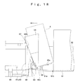
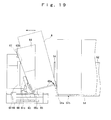
- the bucket unit 60 containing the commodity A is moved in the vertical direction and width direction by the unit moving device 70 to move to the commodity carrying out position.
- the commodity A in the bucket unit 60 is retained in a state in which the commodity A inclines in a width direction that is opposite to the width direction in which the bucket unit 60 moves.
- the restriction releasing member 68 contacts against the operating portion 16 provided adjacent to the opening 15 of the commodity outlet portion 14 and moves diagonally upward to thereby move the rotation restricting member 66 upward.
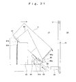
- FIG. 24 shows a flowchart illustrating operations to be performed when a commodity A in a commodity storage column 50 located adjacent to the wall surface on the opposite side to the commodity outlet portion 14 side of the commodity storage chamber 12 is to be carried out to the commodity outlet portion 14.
- the controller 80 receives the commodity A in the bucket 64 from the commodity storage column 50 (step S1), moves the bucket unit 60 a predetermined distance in the width direction to the commodity outlet portion 14 side (step S2), and rotates the bucket 64 to the commodity outlet portion 14 side (step S3).
- the bucket 64 is rotated so that the commodity receiving surface of the bucket 64 faces the commodity storage column 50 side and the predetermined commodity carrying out position side.
- the surface side of the commodity detecting plate 67 that contacts with a commodity is formed in a curved shape so that the center in the width direction of the commodity detecting plate 67 forms a concave portion.
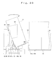
- the angle of inclination of the bucket 64 after the commodity receiving surface of the bucket 64 is rotated to the commodity outlet portion 14 side is arranged to be greater than the angle of inclination of the bucket 64 when receiving the commodity A in the bucket 64 from the commodity storage column 50.
- the angle of inclination of the bucket 64 after the bucket base 62 is moved forward with respect to the unit base 61 is arranged to be smaller than the angle of inclination of the bucket 64 when the commodity A is received in the bucket 64 from the commodity storage column 50. Since it is therefore possible to prevent the commodity A that is received in the bucket 64 from contacting the external door 20, an increase in the dimensions in the front-to-rear direction of the automatic vending machine main unit 10 can be prevented.
- FIG. 26 illustrates a second embodiment of the present invention.
- the same reference symbols are assigned to components that are the same as in the previous embodiment.
- the bucket 64 is composed from a pair of bucket members 64a disposed in the width direction.
- the pair of bucket members 64a are rotatably connected to each other in a condition in which the center in the width direction of the bucket 64 serves as the center of rotation.
- the drop prevention plates 64b contact the side plate 52 of the commodity storage column 50 and rotate downward. Further, when the bucket unit 64 that receives the commodity A is to be moved to the predetermined commodity carrying out position, the drop prevention plates 64b prevent the commodity A from dropping from the bucket 64.
- drop prevention plates for preventing a received commodity A from dropping are provided so as to extend to the commodity receiving surface side from both sides in the width direction of the bucket 64. It is therefore possible to prevent a received commodity A from dropping down from the bucket 64 and to improve the accuracy with respect to carrying out a commodity A.
- the commodity detecting sensor 61e that is turned on/off by the commodity detecting plate 67 is provided in the unit base 61.
- the commodity detecting sensor 61e can similarly detect when a commodity A is sold out or when a fault occurs during an operation to carry out a commodity A.
- the commodity A of a predetermined commodity storage column 50 is sold out, the commodity A of a different commodity storage column 50 can be carried out, and in the case of a failure to receive a commodity A in the bucket 64, the carrying out operation is performed again so that the commodity A can be definitely sold.
Landscapes
- Physics & Mathematics (AREA)
- General Physics & Mathematics (AREA)
- Vending Machines For Individual Products (AREA)
Applications Claiming Priority (1)
| Application Number | Priority Date | Filing Date | Title |
|---|---|---|---|
| JP2007134536 | 2007-05-21 |
Publications (3)
| Publication Number | Publication Date |
|---|---|
| EP2012281A2 true EP2012281A2 (de) | 2009-01-07 |
| EP2012281A3 EP2012281A3 (de) | 2009-11-25 |
| EP2012281B1 EP2012281B1 (de) | 2014-11-19 |
Family
ID=39590744
Family Applications (1)
| Application Number | Title | Priority Date | Filing Date |
|---|---|---|---|
| EP08156361.1A Active EP2012281B1 (de) | 2007-05-21 | 2008-05-16 | Vorrichtung zur Warenausgabe |
Country Status (4)
| Country | Link |
|---|---|
| US (1) | US20080290108A1 (de) |
| EP (1) | EP2012281B1 (de) |
| JP (1) | JP5308713B2 (de) |
| CN (1) | CN101311975B (de) |
Cited By (3)
| Publication number | Priority date | Publication date | Assignee | Title |
|---|---|---|---|---|
| CN106743034A (zh) * | 2017-01-18 | 2017-05-31 | 上海机商实业有限公司 | 一种商品运输装置 |
| CN110120122A (zh) * | 2018-02-05 | 2019-08-13 | 富士电机株式会社 | 自动售货机 |
| CN110419064A (zh) * | 2017-01-12 | 2019-11-05 | 克莱恩销售系统有限公司 | 增强型自动售货机产品传送系统 |
Families Citing this family (17)
| Publication number | Priority date | Publication date | Assignee | Title |
|---|---|---|---|---|
| WO2014030790A1 (ko) * | 2012-08-24 | 2014-02-27 | 수퍼쿨러 주식회사 | 음료 제품 자동판매기 및 자동판매기 온도 제어방법 |
| WO2015019645A1 (ja) * | 2013-08-09 | 2015-02-12 | 富士電機株式会社 | 商品収納装置 |
| CN110246265B (zh) * | 2015-02-27 | 2021-04-27 | 富士电机株式会社 | 商品排出装置 |
| CN105719394B (zh) * | 2016-01-26 | 2019-02-26 | 橙果信息技术有限公司 | 自动售货机取货机械手 |
| CN106157447A (zh) * | 2016-08-02 | 2016-11-23 | 徐海慧 | 一种自动售水机 |
| CN106485834B (zh) * | 2016-09-29 | 2019-07-19 | 江苏蓝天空港设备有限公司 | 自动售货机 |
| US10490014B2 (en) | 2016-12-16 | 2019-11-26 | Pepsico, Inc. | Lean vending machine |
| CN106781002B (zh) * | 2017-01-03 | 2022-06-28 | 上海机商实业有限公司 | 一种连续加热食品的装置 |
| FR3065864B1 (fr) * | 2017-05-05 | 2019-06-28 | Cksquare | Distributeur automatique d'articles ou de produits, en emballages rigides ou souples |
| CN109993915B (zh) * | 2017-12-29 | 2024-07-12 | 山东新北洋信息技术股份有限公司 | 货斗及自动售货机 |
| USD931101S1 (en) | 2018-03-02 | 2021-09-21 | Berlin Packaging, Llc | Closure |
| USD900606S1 (en) | 2018-03-02 | 2020-11-03 | Berlin Packaging, Llc | Closure |
| USD878466S1 (en) * | 2018-06-07 | 2020-03-17 | Vendors Exchange International | Vending machine door |
| CN110766860A (zh) * | 2018-07-27 | 2020-02-07 | 威海新北洋数码科技有限公司 | 一种自动售货机 |
| CN110796790B (zh) * | 2018-08-03 | 2021-05-28 | 威海新北洋数码科技有限公司 | 一种货斗及自动售货机 |
| US10867463B2 (en) * | 2018-09-18 | 2020-12-15 | Pepsico, Inc. | Vending machine |
| JP7534936B2 (ja) * | 2020-11-27 | 2024-08-15 | 株式会社小松製作所 | ホイールローダの制御システム、方法、およびホイールローダ |
Citations (2)
| Publication number | Priority date | Publication date | Assignee | Title |
|---|---|---|---|---|
| FR2718624A1 (fr) | 1994-04-14 | 1995-10-20 | Blanc Roger | Installation pour restauration rapide. |
| JP2000076535A (ja) | 1998-08-27 | 2000-03-14 | Toshiba Corp | 自動販売機 |
Family Cites Families (19)
| Publication number | Priority date | Publication date | Assignee | Title |
|---|---|---|---|---|
| JPS4827959B1 (de) * | 1969-01-22 | 1973-08-28 | ||
| IT1169483B (it) * | 1982-12-08 | 1987-05-27 | Sanden Corp | Meccanismo erogatore per macchine distributrici o simili |
| JPS6324529Y2 (de) * | 1984-12-28 | 1988-07-05 | ||
| JPH0397777U (de) * | 1990-01-29 | 1991-10-08 | ||
| US5570811A (en) * | 1994-11-01 | 1996-11-05 | Fawn Engineering Corporation | Apparatus and method for dispensing items from a vending machine |
| US6230930B1 (en) * | 1997-10-14 | 2001-05-15 | Cross-Given Manufacturing Company | Apparatus and method for vending products |
| US6513677B1 (en) * | 1997-10-14 | 2003-02-04 | Gross-Given Manufacturing Company | Apparatus and method for vending products |
| US6241121B1 (en) * | 1998-03-31 | 2001-06-05 | Sanyo Electric Co., Ltd | Commodity accommodating unit of an automatic vending machine |
| US6283324B1 (en) * | 1999-01-08 | 2001-09-04 | Stuart M. Jenkins | Coin roll dispensing apparatus |
| WO2003074396A1 (en) * | 2002-03-04 | 2003-09-12 | Alexandre Maldonado | Adjustable push forward dispensing mechanism |
| EP1162582A3 (de) * | 2000-06-05 | 2003-03-12 | Sanden Corporation | Verkaufsautomat |
| JP2002092725A (ja) * | 2000-09-20 | 2002-03-29 | Fuji Electric Co Ltd | 自動販売機 |
| FI107721B (fi) * | 2000-10-27 | 2001-09-28 | Jypa Automaatio Oy | Valinta-automaatti |
| JP3952996B2 (ja) * | 2003-06-17 | 2007-08-01 | 富士電機リテイルシステムズ株式会社 | 自動販売機 |
| US7222748B2 (en) * | 2003-09-26 | 2007-05-29 | Royal Vendors, Inc. | Clear door vending machine |
| CA2557607A1 (en) * | 2004-02-27 | 2005-09-15 | Sandenvendo America, Inc. | Vending machine and component parts |
| JP4285331B2 (ja) * | 2004-06-01 | 2009-06-24 | 富士電機リテイルシステムズ株式会社 | 自動販売機の商品搬出装置 |
| JP4779932B2 (ja) * | 2006-10-30 | 2011-09-28 | 富士電機リテイルシステムズ株式会社 | 自動販売機の商品搬出装置 |
| US20080142537A1 (en) * | 2006-12-14 | 2008-06-19 | The Coca-Cola Company | First in First Out Vending Systems |
-
2008
- 2008-05-16 EP EP08156361.1A patent/EP2012281B1/de active Active
- 2008-05-19 JP JP2008130961A patent/JP5308713B2/ja not_active Expired - Fee Related
- 2008-05-21 US US12/124,811 patent/US20080290108A1/en not_active Abandoned
- 2008-05-21 CN CN2008101079640A patent/CN101311975B/zh not_active Expired - Fee Related
Patent Citations (2)
| Publication number | Priority date | Publication date | Assignee | Title |
|---|---|---|---|---|
| FR2718624A1 (fr) | 1994-04-14 | 1995-10-20 | Blanc Roger | Installation pour restauration rapide. |
| JP2000076535A (ja) | 1998-08-27 | 2000-03-14 | Toshiba Corp | 自動販売機 |
Cited By (7)
| Publication number | Priority date | Publication date | Assignee | Title |
|---|---|---|---|---|
| CN110419064A (zh) * | 2017-01-12 | 2019-11-05 | 克莱恩销售系统有限公司 | 增强型自动售货机产品传送系统 |
| EP3568841A4 (de) * | 2017-01-12 | 2020-10-28 | Crane Merchandising Systems, Inc. | Verbessertes produktabgabesystem für verkaufsautomat |
| US11631294B2 (en) | 2017-01-12 | 2023-04-18 | Crane Payment Innovations, Inc. | Enhanced vending machine product delivery system |
| CN106743034A (zh) * | 2017-01-18 | 2017-05-31 | 上海机商实业有限公司 | 一种商品运输装置 |
| CN106743034B (zh) * | 2017-01-18 | 2019-07-02 | 上海机商实业有限公司 | 一种商品运输装置 |
| CN110120122A (zh) * | 2018-02-05 | 2019-08-13 | 富士电机株式会社 | 自动售货机 |
| CN110120122B (zh) * | 2018-02-05 | 2022-09-20 | 富士电机株式会社 | 自动售货机 |
Also Published As
| Publication number | Publication date |
|---|---|
| CN101311975A (zh) | 2008-11-26 |
| JP2009003924A (ja) | 2009-01-08 |
| US20080290108A1 (en) | 2008-11-27 |
| JP5308713B2 (ja) | 2013-10-09 |
| EP2012281B1 (de) | 2014-11-19 |
| CN101311975B (zh) | 2013-01-02 |
| EP2012281A3 (de) | 2009-11-25 |
Similar Documents
| Publication | Publication Date | Title |
|---|---|---|
| EP2012281B1 (de) | Vorrichtung zur Warenausgabe | |
| EP2383708B1 (de) | Vorrichtung zur Warenausgabe | |
| JP5853526B2 (ja) | 自動販売機 | |
| CN107103689B (zh) | 自动售货机 | |
| CN107195099B (zh) | 自动售货机的商品送出装置 | |
| CN106415675B (zh) | 商品排出装置 | |
| JP5668545B2 (ja) | 商品収納装置 | |
| CN105874515B (zh) | 商品收纳装置 | |
| CN104541310B (zh) | 商品收纳装置 | |
| JP4175993B2 (ja) | 自動販売機の商品搬出装置 | |
| JP6686720B2 (ja) | 自動販売機 | |
| CN107004328B (zh) | 商品排出装置 | |
| JP4839561B2 (ja) | 自動販売機の商品ラック | |
| JP3671710B2 (ja) | 移動仕切り装置を備えた自動販売機 | |
| JP6672634B2 (ja) | 商品収納装置 | |
| JP5742328B2 (ja) | 商品収納装置 | |
| JP5691963B2 (ja) | 自動販売機 | |
| JP5668546B2 (ja) | 商品収納装置 | |
| CN107209972A (zh) | 商品排出装置 | |
| JP2005128682A (ja) | 自動販売機 | |
| JPH0962923A (ja) | 自動販売機の商品搬出装置 | |
| JPH06290340A (ja) | 自動販売機の商品搬出装置 |
Legal Events
| Date | Code | Title | Description |
|---|---|---|---|
| PUAI | Public reference made under article 153(3) epc to a published international application that has entered the european phase |
Free format text: ORIGINAL CODE: 0009012 |
|
| AK | Designated contracting states |
Kind code of ref document: A2 Designated state(s): AT BE BG CH CY CZ DE DK EE ES FI FR GB GR HR HU IE IS IT LI LT LU LV MC MT NL NO PL PT RO SE SI SK TR |
|
| AX | Request for extension of the european patent |
Extension state: AL BA MK RS |
|
| PUAL | Search report despatched |
Free format text: ORIGINAL CODE: 0009013 |
|
| AK | Designated contracting states |
Kind code of ref document: A3 Designated state(s): AT BE BG CH CY CZ DE DK EE ES FI FR GB GR HR HU IE IS IT LI LT LU LV MC MT NL NO PL PT RO SE SI SK TR |
|
| AX | Request for extension of the european patent |
Extension state: AL BA MK RS |
|
| 17P | Request for examination filed |
Effective date: 20100514 |
|
| AKX | Designation fees paid |
Designated state(s): AT BE BG CH CY CZ DE DK EE ES FI FR GB GR HR HU IE IS IT LI LT LU LV MC MT NL NO PL PT RO SE SI SK TR |
|
| 17Q | First examination report despatched |
Effective date: 20110930 |
|
| GRAP | Despatch of communication of intention to grant a patent |
Free format text: ORIGINAL CODE: EPIDOSNIGR1 |
|
| INTG | Intention to grant announced |
Effective date: 20140806 |
|
| GRAS | Grant fee paid |
Free format text: ORIGINAL CODE: EPIDOSNIGR3 |
|
| GRAA | (expected) grant |
Free format text: ORIGINAL CODE: 0009210 |
|
| AK | Designated contracting states |
Kind code of ref document: B1 Designated state(s): AT BE BG CH CY CZ DE DK EE ES FI FR GB GR HR HU IE IS IT LI LT LU LV MC MT NL NO PL PT RO SE SI SK TR |
|
| REG | Reference to a national code |
Ref country code: GB Ref legal event code: FG4D |
|
| REG | Reference to a national code |
Ref country code: CH Ref legal event code: EP |
|
| REG | Reference to a national code |
Ref country code: AT Ref legal event code: REF Ref document number: 697407 Country of ref document: AT Kind code of ref document: T Effective date: 20141215 |
|
| REG | Reference to a national code |
Ref country code: IE Ref legal event code: FG4D |
|
| REG | Reference to a national code |
Ref country code: DE Ref legal event code: R096 Ref document number: 602008035423 Country of ref document: DE Effective date: 20141231 |
|
| REG | Reference to a national code |
Ref country code: NL Ref legal event code: VDEP Effective date: 20141119 |
|
| REG | Reference to a national code |
Ref country code: AT Ref legal event code: MK05 Ref document number: 697407 Country of ref document: AT Kind code of ref document: T Effective date: 20141119 |
|
| REG | Reference to a national code |
Ref country code: LT Ref legal event code: MG4D |
|
| PG25 | Lapsed in a contracting state [announced via postgrant information from national office to epo] |
Ref country code: NL Free format text: LAPSE BECAUSE OF FAILURE TO SUBMIT A TRANSLATION OF THE DESCRIPTION OR TO PAY THE FEE WITHIN THE PRESCRIBED TIME-LIMIT Effective date: 20141119 Ref country code: NO Free format text: LAPSE BECAUSE OF FAILURE TO SUBMIT A TRANSLATION OF THE DESCRIPTION OR TO PAY THE FEE WITHIN THE PRESCRIBED TIME-LIMIT Effective date: 20150219 Ref country code: LT Free format text: LAPSE BECAUSE OF FAILURE TO SUBMIT A TRANSLATION OF THE DESCRIPTION OR TO PAY THE FEE WITHIN THE PRESCRIBED TIME-LIMIT Effective date: 20141119 Ref country code: PT Free format text: LAPSE BECAUSE OF FAILURE TO SUBMIT A TRANSLATION OF THE DESCRIPTION OR TO PAY THE FEE WITHIN THE PRESCRIBED TIME-LIMIT Effective date: 20150319 Ref country code: ES Free format text: LAPSE BECAUSE OF FAILURE TO SUBMIT A TRANSLATION OF THE DESCRIPTION OR TO PAY THE FEE WITHIN THE PRESCRIBED TIME-LIMIT Effective date: 20141119 Ref country code: IS Free format text: LAPSE BECAUSE OF FAILURE TO SUBMIT A TRANSLATION OF THE DESCRIPTION OR TO PAY THE FEE WITHIN THE PRESCRIBED TIME-LIMIT Effective date: 20150319 Ref country code: FI Free format text: LAPSE BECAUSE OF FAILURE TO SUBMIT A TRANSLATION OF THE DESCRIPTION OR TO PAY THE FEE WITHIN THE PRESCRIBED TIME-LIMIT Effective date: 20141119 |
|
| PG25 | Lapsed in a contracting state [announced via postgrant information from national office to epo] |
Ref country code: HR Free format text: LAPSE BECAUSE OF FAILURE TO SUBMIT A TRANSLATION OF THE DESCRIPTION OR TO PAY THE FEE WITHIN THE PRESCRIBED TIME-LIMIT Effective date: 20141119 Ref country code: SE Free format text: LAPSE BECAUSE OF FAILURE TO SUBMIT A TRANSLATION OF THE DESCRIPTION OR TO PAY THE FEE WITHIN THE PRESCRIBED TIME-LIMIT Effective date: 20141119 Ref country code: PL Free format text: LAPSE BECAUSE OF FAILURE TO SUBMIT A TRANSLATION OF THE DESCRIPTION OR TO PAY THE FEE WITHIN THE PRESCRIBED TIME-LIMIT Effective date: 20141119 Ref country code: LV Free format text: LAPSE BECAUSE OF FAILURE TO SUBMIT A TRANSLATION OF THE DESCRIPTION OR TO PAY THE FEE WITHIN THE PRESCRIBED TIME-LIMIT Effective date: 20141119 Ref country code: GR Free format text: LAPSE BECAUSE OF FAILURE TO SUBMIT A TRANSLATION OF THE DESCRIPTION OR TO PAY THE FEE WITHIN THE PRESCRIBED TIME-LIMIT Effective date: 20150220 Ref country code: CY Free format text: LAPSE BECAUSE OF FAILURE TO SUBMIT A TRANSLATION OF THE DESCRIPTION OR TO PAY THE FEE WITHIN THE PRESCRIBED TIME-LIMIT Effective date: 20141119 Ref country code: AT Free format text: LAPSE BECAUSE OF FAILURE TO SUBMIT A TRANSLATION OF THE DESCRIPTION OR TO PAY THE FEE WITHIN THE PRESCRIBED TIME-LIMIT Effective date: 20141119 |
|
| PG25 | Lapsed in a contracting state [announced via postgrant information from national office to epo] |
Ref country code: CZ Free format text: LAPSE BECAUSE OF FAILURE TO SUBMIT A TRANSLATION OF THE DESCRIPTION OR TO PAY THE FEE WITHIN THE PRESCRIBED TIME-LIMIT Effective date: 20141119 Ref country code: DK Free format text: LAPSE BECAUSE OF FAILURE TO SUBMIT A TRANSLATION OF THE DESCRIPTION OR TO PAY THE FEE WITHIN THE PRESCRIBED TIME-LIMIT Effective date: 20141119 Ref country code: SK Free format text: LAPSE BECAUSE OF FAILURE TO SUBMIT A TRANSLATION OF THE DESCRIPTION OR TO PAY THE FEE WITHIN THE PRESCRIBED TIME-LIMIT Effective date: 20141119 Ref country code: RO Free format text: LAPSE BECAUSE OF FAILURE TO SUBMIT A TRANSLATION OF THE DESCRIPTION OR TO PAY THE FEE WITHIN THE PRESCRIBED TIME-LIMIT Effective date: 20141119 Ref country code: EE Free format text: LAPSE BECAUSE OF FAILURE TO SUBMIT A TRANSLATION OF THE DESCRIPTION OR TO PAY THE FEE WITHIN THE PRESCRIBED TIME-LIMIT Effective date: 20141119 |
|
| REG | Reference to a national code |
Ref country code: DE Ref legal event code: R097 Ref document number: 602008035423 Country of ref document: DE |
|
| PLBE | No opposition filed within time limit |
Free format text: ORIGINAL CODE: 0009261 |
|
| STAA | Information on the status of an ep patent application or granted ep patent |
Free format text: STATUS: NO OPPOSITION FILED WITHIN TIME LIMIT |
|
| 26N | No opposition filed |
Effective date: 20150820 |
|
| PG25 | Lapsed in a contracting state [announced via postgrant information from national office to epo] |
Ref country code: IT Free format text: LAPSE BECAUSE OF FAILURE TO SUBMIT A TRANSLATION OF THE DESCRIPTION OR TO PAY THE FEE WITHIN THE PRESCRIBED TIME-LIMIT Effective date: 20141119 |
|
| REG | Reference to a national code |
Ref country code: CH Ref legal event code: PL |
|
| GBPC | Gb: european patent ceased through non-payment of renewal fee |
Effective date: 20150516 |
|
| PG25 | Lapsed in a contracting state [announced via postgrant information from national office to epo] |
Ref country code: LU Free format text: LAPSE BECAUSE OF FAILURE TO SUBMIT A TRANSLATION OF THE DESCRIPTION OR TO PAY THE FEE WITHIN THE PRESCRIBED TIME-LIMIT Effective date: 20150516 Ref country code: LI Free format text: LAPSE BECAUSE OF NON-PAYMENT OF DUE FEES Effective date: 20150531 Ref country code: CH Free format text: LAPSE BECAUSE OF NON-PAYMENT OF DUE FEES Effective date: 20150531 Ref country code: MC Free format text: LAPSE BECAUSE OF FAILURE TO SUBMIT A TRANSLATION OF THE DESCRIPTION OR TO PAY THE FEE WITHIN THE PRESCRIBED TIME-LIMIT Effective date: 20141119 |
|
| REG | Reference to a national code |
Ref country code: IE Ref legal event code: MM4A |
|
| REG | Reference to a national code |
Ref country code: FR Ref legal event code: ST Effective date: 20160129 |
|
| PG25 | Lapsed in a contracting state [announced via postgrant information from national office to epo] |
Ref country code: SI Free format text: LAPSE BECAUSE OF FAILURE TO SUBMIT A TRANSLATION OF THE DESCRIPTION OR TO PAY THE FEE WITHIN THE PRESCRIBED TIME-LIMIT Effective date: 20141119 |
|
| REG | Reference to a national code |
Ref country code: DE Ref legal event code: R081 Ref document number: 602008035423 Country of ref document: DE Owner name: SANDEN RETAIL SYSTEMS CORPORATION, ISESAKI-SHI, JP Free format text: FORMER OWNER: SANDEN CORP., ISESAKI-SHI, GUNMA-KEN, JP Ref country code: DE Ref legal event code: R081 Ref document number: 602008035423 Country of ref document: DE Owner name: SANDEN HOLDINGS CORPORATION, LSESAKI-SHI, JP Free format text: FORMER OWNER: SANDEN CORP., ISESAKI-SHI, GUNMA-KEN, JP |
|
| PG25 | Lapsed in a contracting state [announced via postgrant information from national office to epo] |
Ref country code: GB Free format text: LAPSE BECAUSE OF NON-PAYMENT OF DUE FEES Effective date: 20150516 Ref country code: IE Free format text: LAPSE BECAUSE OF NON-PAYMENT OF DUE FEES Effective date: 20150516 |
|
| PG25 | Lapsed in a contracting state [announced via postgrant information from national office to epo] |
Ref country code: FR Free format text: LAPSE BECAUSE OF NON-PAYMENT OF DUE FEES Effective date: 20150601 |
|
| PG25 | Lapsed in a contracting state [announced via postgrant information from national office to epo] |
Ref country code: MT Free format text: LAPSE BECAUSE OF FAILURE TO SUBMIT A TRANSLATION OF THE DESCRIPTION OR TO PAY THE FEE WITHIN THE PRESCRIBED TIME-LIMIT Effective date: 20141119 |
|
| PG25 | Lapsed in a contracting state [announced via postgrant information from national office to epo] |
Ref country code: BG Free format text: LAPSE BECAUSE OF FAILURE TO SUBMIT A TRANSLATION OF THE DESCRIPTION OR TO PAY THE FEE WITHIN THE PRESCRIBED TIME-LIMIT Effective date: 20141119 Ref country code: HU Free format text: LAPSE BECAUSE OF FAILURE TO SUBMIT A TRANSLATION OF THE DESCRIPTION OR TO PAY THE FEE WITHIN THE PRESCRIBED TIME-LIMIT; INVALID AB INITIO Effective date: 20080516 |
|
| PG25 | Lapsed in a contracting state [announced via postgrant information from national office to epo] |
Ref country code: TR Free format text: LAPSE BECAUSE OF FAILURE TO SUBMIT A TRANSLATION OF THE DESCRIPTION OR TO PAY THE FEE WITHIN THE PRESCRIBED TIME-LIMIT Effective date: 20141119 |
|
| PG25 | Lapsed in a contracting state [announced via postgrant information from national office to epo] |
Ref country code: BE Free format text: LAPSE BECAUSE OF FAILURE TO SUBMIT A TRANSLATION OF THE DESCRIPTION OR TO PAY THE FEE WITHIN THE PRESCRIBED TIME-LIMIT Effective date: 20141119 |
|
| REG | Reference to a national code |
Ref country code: DE Ref legal event code: R081 Ref document number: 602008035423 Country of ref document: DE Owner name: SANDEN RETAIL SYSTEMS CORPORATION, ISESAKI-SHI, JP Free format text: FORMER OWNER: SANDEN HOLDINGS CORPORATION, LSESAKI-SHI, GUNMA, JP |
|
| PGFP | Annual fee paid to national office [announced via postgrant information from national office to epo] |
Ref country code: DE Payment date: 20250521 Year of fee payment: 18 |