EP2010691B1 - Beschichteter körper - Google Patents
Beschichteter körper Download PDFInfo
- Publication number
- EP2010691B1 EP2010691B1 EP07724445.7A EP07724445A EP2010691B1 EP 2010691 B1 EP2010691 B1 EP 2010691B1 EP 07724445 A EP07724445 A EP 07724445A EP 2010691 B1 EP2010691 B1 EP 2010691B1
- Authority
- EP
- European Patent Office
- Prior art keywords
- layer
- hard material
- material layer
- cutting tool
- metallic elements
- Prior art date
- Legal status (The legal status is an assumption and is not a legal conclusion. Google has not performed a legal analysis and makes no representation as to the accuracy of the status listed.)
- Active
Links
Images

Classifications
-
- C—CHEMISTRY; METALLURGY
- C23—COATING METALLIC MATERIAL; COATING MATERIAL WITH METALLIC MATERIAL; CHEMICAL SURFACE TREATMENT; DIFFUSION TREATMENT OF METALLIC MATERIAL; COATING BY VACUUM EVAPORATION, BY SPUTTERING, BY ION IMPLANTATION OR BY CHEMICAL VAPOUR DEPOSITION, IN GENERAL; INHIBITING CORROSION OF METALLIC MATERIAL OR INCRUSTATION IN GENERAL
- C23C—COATING METALLIC MATERIAL; COATING MATERIAL WITH METALLIC MATERIAL; SURFACE TREATMENT OF METALLIC MATERIAL BY DIFFUSION INTO THE SURFACE, BY CHEMICAL CONVERSION OR SUBSTITUTION; COATING BY VACUUM EVAPORATION, BY SPUTTERING, BY ION IMPLANTATION OR BY CHEMICAL VAPOUR DEPOSITION, IN GENERAL
- C23C14/00—Coating by vacuum evaporation, by sputtering or by ion implantation of the coating forming material
- C23C14/06—Coating by vacuum evaporation, by sputtering or by ion implantation of the coating forming material characterised by the coating material
- C23C14/08—Oxides
-
- C—CHEMISTRY; METALLURGY
- C23—COATING METALLIC MATERIAL; COATING MATERIAL WITH METALLIC MATERIAL; CHEMICAL SURFACE TREATMENT; DIFFUSION TREATMENT OF METALLIC MATERIAL; COATING BY VACUUM EVAPORATION, BY SPUTTERING, BY ION IMPLANTATION OR BY CHEMICAL VAPOUR DEPOSITION, IN GENERAL; INHIBITING CORROSION OF METALLIC MATERIAL OR INCRUSTATION IN GENERAL
- C23C—COATING METALLIC MATERIAL; COATING MATERIAL WITH METALLIC MATERIAL; SURFACE TREATMENT OF METALLIC MATERIAL BY DIFFUSION INTO THE SURFACE, BY CHEMICAL CONVERSION OR SUBSTITUTION; COATING BY VACUUM EVAPORATION, BY SPUTTERING, BY ION IMPLANTATION OR BY CHEMICAL VAPOUR DEPOSITION, IN GENERAL
- C23C14/00—Coating by vacuum evaporation, by sputtering or by ion implantation of the coating forming material
- C23C14/06—Coating by vacuum evaporation, by sputtering or by ion implantation of the coating forming material characterised by the coating material
- C23C14/0641—Nitrides
-
- C—CHEMISTRY; METALLURGY
- C23—COATING METALLIC MATERIAL; COATING MATERIAL WITH METALLIC MATERIAL; CHEMICAL SURFACE TREATMENT; DIFFUSION TREATMENT OF METALLIC MATERIAL; COATING BY VACUUM EVAPORATION, BY SPUTTERING, BY ION IMPLANTATION OR BY CHEMICAL VAPOUR DEPOSITION, IN GENERAL; INHIBITING CORROSION OF METALLIC MATERIAL OR INCRUSTATION IN GENERAL
- C23C—COATING METALLIC MATERIAL; COATING MATERIAL WITH METALLIC MATERIAL; SURFACE TREATMENT OF METALLIC MATERIAL BY DIFFUSION INTO THE SURFACE, BY CHEMICAL CONVERSION OR SUBSTITUTION; COATING BY VACUUM EVAPORATION, BY SPUTTERING, BY ION IMPLANTATION OR BY CHEMICAL VAPOUR DEPOSITION, IN GENERAL
- C23C14/00—Coating by vacuum evaporation, by sputtering or by ion implantation of the coating forming material
- C23C14/06—Coating by vacuum evaporation, by sputtering or by ion implantation of the coating forming material characterised by the coating material
- C23C14/0676—Oxynitrides
-
- C—CHEMISTRY; METALLURGY
- C23—COATING METALLIC MATERIAL; COATING MATERIAL WITH METALLIC MATERIAL; CHEMICAL SURFACE TREATMENT; DIFFUSION TREATMENT OF METALLIC MATERIAL; COATING BY VACUUM EVAPORATION, BY SPUTTERING, BY ION IMPLANTATION OR BY CHEMICAL VAPOUR DEPOSITION, IN GENERAL; INHIBITING CORROSION OF METALLIC MATERIAL OR INCRUSTATION IN GENERAL
- C23C—COATING METALLIC MATERIAL; COATING MATERIAL WITH METALLIC MATERIAL; SURFACE TREATMENT OF METALLIC MATERIAL BY DIFFUSION INTO THE SURFACE, BY CHEMICAL CONVERSION OR SUBSTITUTION; COATING BY VACUUM EVAPORATION, BY SPUTTERING, BY ION IMPLANTATION OR BY CHEMICAL VAPOUR DEPOSITION, IN GENERAL
- C23C14/00—Coating by vacuum evaporation, by sputtering or by ion implantation of the coating forming material
- C23C14/22—Coating by vacuum evaporation, by sputtering or by ion implantation of the coating forming material characterised by the process of coating
- C23C14/34—Sputtering
- C23C14/35—Sputtering by application of a magnetic field, e.g. magnetron sputtering
- C23C14/352—Sputtering by application of a magnetic field, e.g. magnetron sputtering using more than one target
-
- C—CHEMISTRY; METALLURGY
- C23—COATING METALLIC MATERIAL; COATING MATERIAL WITH METALLIC MATERIAL; CHEMICAL SURFACE TREATMENT; DIFFUSION TREATMENT OF METALLIC MATERIAL; COATING BY VACUUM EVAPORATION, BY SPUTTERING, BY ION IMPLANTATION OR BY CHEMICAL VAPOUR DEPOSITION, IN GENERAL; INHIBITING CORROSION OF METALLIC MATERIAL OR INCRUSTATION IN GENERAL
- C23C—COATING METALLIC MATERIAL; COATING MATERIAL WITH METALLIC MATERIAL; SURFACE TREATMENT OF METALLIC MATERIAL BY DIFFUSION INTO THE SURFACE, BY CHEMICAL CONVERSION OR SUBSTITUTION; COATING BY VACUUM EVAPORATION, BY SPUTTERING, BY ION IMPLANTATION OR BY CHEMICAL VAPOUR DEPOSITION, IN GENERAL
- C23C28/00—Coating for obtaining at least two superposed coatings either by methods not provided for in a single one of groups C23C2/00 - C23C26/00 or by combinations of methods provided for in subclasses C23C and C25C or C25D
- C23C28/04—Coating for obtaining at least two superposed coatings either by methods not provided for in a single one of groups C23C2/00 - C23C26/00 or by combinations of methods provided for in subclasses C23C and C25C or C25D only coatings of inorganic non-metallic material
- C23C28/042—Coating for obtaining at least two superposed coatings either by methods not provided for in a single one of groups C23C2/00 - C23C26/00 or by combinations of methods provided for in subclasses C23C and C25C or C25D only coatings of inorganic non-metallic material including a refractory ceramic layer, e.g. refractory metal oxides, ZrO2, rare earth oxides
-
- C—CHEMISTRY; METALLURGY
- C23—COATING METALLIC MATERIAL; COATING MATERIAL WITH METALLIC MATERIAL; CHEMICAL SURFACE TREATMENT; DIFFUSION TREATMENT OF METALLIC MATERIAL; COATING BY VACUUM EVAPORATION, BY SPUTTERING, BY ION IMPLANTATION OR BY CHEMICAL VAPOUR DEPOSITION, IN GENERAL; INHIBITING CORROSION OF METALLIC MATERIAL OR INCRUSTATION IN GENERAL
- C23C—COATING METALLIC MATERIAL; COATING MATERIAL WITH METALLIC MATERIAL; SURFACE TREATMENT OF METALLIC MATERIAL BY DIFFUSION INTO THE SURFACE, BY CHEMICAL CONVERSION OR SUBSTITUTION; COATING BY VACUUM EVAPORATION, BY SPUTTERING, BY ION IMPLANTATION OR BY CHEMICAL VAPOUR DEPOSITION, IN GENERAL
- C23C28/00—Coating for obtaining at least two superposed coatings either by methods not provided for in a single one of groups C23C2/00 - C23C26/00 or by combinations of methods provided for in subclasses C23C and C25C or C25D
- C23C28/04—Coating for obtaining at least two superposed coatings either by methods not provided for in a single one of groups C23C2/00 - C23C26/00 or by combinations of methods provided for in subclasses C23C and C25C or C25D only coatings of inorganic non-metallic material
- C23C28/044—Coating for obtaining at least two superposed coatings either by methods not provided for in a single one of groups C23C2/00 - C23C26/00 or by combinations of methods provided for in subclasses C23C and C25C or C25D only coatings of inorganic non-metallic material coatings specially adapted for cutting tools or wear applications
-
- C—CHEMISTRY; METALLURGY
- C23—COATING METALLIC MATERIAL; COATING MATERIAL WITH METALLIC MATERIAL; CHEMICAL SURFACE TREATMENT; DIFFUSION TREATMENT OF METALLIC MATERIAL; COATING BY VACUUM EVAPORATION, BY SPUTTERING, BY ION IMPLANTATION OR BY CHEMICAL VAPOUR DEPOSITION, IN GENERAL; INHIBITING CORROSION OF METALLIC MATERIAL OR INCRUSTATION IN GENERAL
- C23C—COATING METALLIC MATERIAL; COATING MATERIAL WITH METALLIC MATERIAL; SURFACE TREATMENT OF METALLIC MATERIAL BY DIFFUSION INTO THE SURFACE, BY CHEMICAL CONVERSION OR SUBSTITUTION; COATING BY VACUUM EVAPORATION, BY SPUTTERING, BY ION IMPLANTATION OR BY CHEMICAL VAPOUR DEPOSITION, IN GENERAL
- C23C28/00—Coating for obtaining at least two superposed coatings either by methods not provided for in a single one of groups C23C2/00 - C23C26/00 or by combinations of methods provided for in subclasses C23C and C25C or C25D
- C23C28/04—Coating for obtaining at least two superposed coatings either by methods not provided for in a single one of groups C23C2/00 - C23C26/00 or by combinations of methods provided for in subclasses C23C and C25C or C25D only coatings of inorganic non-metallic material
- C23C28/048—Coating for obtaining at least two superposed coatings either by methods not provided for in a single one of groups C23C2/00 - C23C26/00 or by combinations of methods provided for in subclasses C23C and C25C or C25D only coatings of inorganic non-metallic material with layers graded in composition or physical properties
-
- C—CHEMISTRY; METALLURGY
- C23—COATING METALLIC MATERIAL; COATING MATERIAL WITH METALLIC MATERIAL; CHEMICAL SURFACE TREATMENT; DIFFUSION TREATMENT OF METALLIC MATERIAL; COATING BY VACUUM EVAPORATION, BY SPUTTERING, BY ION IMPLANTATION OR BY CHEMICAL VAPOUR DEPOSITION, IN GENERAL; INHIBITING CORROSION OF METALLIC MATERIAL OR INCRUSTATION IN GENERAL
- C23C—COATING METALLIC MATERIAL; COATING MATERIAL WITH METALLIC MATERIAL; SURFACE TREATMENT OF METALLIC MATERIAL BY DIFFUSION INTO THE SURFACE, BY CHEMICAL CONVERSION OR SUBSTITUTION; COATING BY VACUUM EVAPORATION, BY SPUTTERING, BY ION IMPLANTATION OR BY CHEMICAL VAPOUR DEPOSITION, IN GENERAL
- C23C28/00—Coating for obtaining at least two superposed coatings either by methods not provided for in a single one of groups C23C2/00 - C23C26/00 or by combinations of methods provided for in subclasses C23C and C25C or C25D
- C23C28/40—Coatings including alternating layers following a pattern, a periodic or defined repetition
- C23C28/42—Coatings including alternating layers following a pattern, a periodic or defined repetition characterized by the composition of the alternating layers
-
- C—CHEMISTRY; METALLURGY
- C23—COATING METALLIC MATERIAL; COATING MATERIAL WITH METALLIC MATERIAL; CHEMICAL SURFACE TREATMENT; DIFFUSION TREATMENT OF METALLIC MATERIAL; COATING BY VACUUM EVAPORATION, BY SPUTTERING, BY ION IMPLANTATION OR BY CHEMICAL VAPOUR DEPOSITION, IN GENERAL; INHIBITING CORROSION OF METALLIC MATERIAL OR INCRUSTATION IN GENERAL
- C23C—COATING METALLIC MATERIAL; COATING MATERIAL WITH METALLIC MATERIAL; SURFACE TREATMENT OF METALLIC MATERIAL BY DIFFUSION INTO THE SURFACE, BY CHEMICAL CONVERSION OR SUBSTITUTION; COATING BY VACUUM EVAPORATION, BY SPUTTERING, BY ION IMPLANTATION OR BY CHEMICAL VAPOUR DEPOSITION, IN GENERAL
- C23C30/00—Coating with metallic material characterised only by the composition of the metallic material, i.e. not characterised by the coating process
- C23C30/005—Coating with metallic material characterised only by the composition of the metallic material, i.e. not characterised by the coating process on hard metal substrates
-
- H—ELECTRICITY
- H01—ELECTRIC ELEMENTS
- H01J—ELECTRIC DISCHARGE TUBES OR DISCHARGE LAMPS
- H01J37/00—Discharge tubes with provision for introducing objects or material to be exposed to the discharge, e.g. for the purpose of examination or processing thereof
- H01J37/32—Gas-filled discharge tubes
- H01J37/34—Gas-filled discharge tubes operating with cathodic sputtering
- H01J37/3464—Operating strategies
- H01J37/3467—Pulsed operation, e.g. HIPIMS
Definitions
- the invention relates to a cutting tool for machining with a substrate and a hard material layer applied to the substrate and to a method for producing a hard material layer.
- Coated bodies comprise a substrate material and one or more layers deposited thereon.
- tools for example drills, milling cutters or indexable inserts
- a substrate material for example HSS steel or hard metal.
- hard material layers can be formed. These layers are particularly useful for improving hardness, hot hardness, wear resistance, frictional properties, chemical resistance and oxidation resistance.
- layers of aluminum oxide have proven useful. These are often applied with the CVD technique.
- the CVD technique uses high temperatures, which leads to a corresponding load on the substrates, and to high tensile stresses in the layer.
- Another disadvantage is u. A. the contamination with halogens. Since steel materials soften at high temperatures, CVD coatings for tools and wearing parts are mainly applied to cemented carbide. But even these relatively temperature-resistant substrates are embrittled in CVD by eta-phase formation in the surface.
- the high temperatures due to the different thermal expansion lead to the harmful high tensile stresses known in CVD. Therefore, the layers usually have a crack network that weakens the composite layer and worsens the corrosion protection of the layer.
- PVD methods by arc evaporation (Are method) in which the metallic element is evaporated on the molten phase and on the other hand, the magnetron sputtering, are used in the targets of the material to be sputtered as the cathode of a low-pressure electrical discharge, wherein ions of the Plasmas atomize the targets.
- Re method arc evaporation
- the magnetron sputtering are used in the targets of the material to be sputtered as the cathode of a low-pressure electrical discharge, wherein ions of the Plasmas atomize the targets.
- the hard coating is applied by means of a PVD process, in which on the one hand the material of an AIP target (Arc discharge Ion Plating) with the aid of arc evaporation and on the other hand the material of an MS target (Magentron Sputtering) with magnetron rods is transferred into a plasma.
- AIP target Arc discharge Ion Plating
- MS target Magneticentron Sputtering
- oxygen-containing process gases are supplied.
- the layer comprises the metal elements Si and at least one further element selected from the transition metals of groups 4a, 4a and 6a of the Periodic Table, Al and B.
- the coating also comprises non-metallic elements selected from C, N and O. Oxygen becomes Improved lubrication used, however, the proportion of oxygen to the non-metallic elements is limited to 5 At .-%.
- the layer includes, among others, the metallic elements Al, Cr, and Si and the non-metallic elements N, B, C, and O. Numerous combinations are cited with said elements, but the oxygen content among the non-metallic elements does not exceed 25 at. % addition.
- compositions obtained here are (Ti 0.2 , Cr 0.2 , Al 0.55 , Si 0.05 ) N, (Ti 0.15 , Cr 0.2 , Al 0.6 , Si 0.05 ) N, (Ti 0.2 , Cr 0.23 , Al 0.53 , Si 0.04 ) N , (Ti 0.14 , Cr 0.22 , Al 0.59 , Si 0.05 ) N.
- coated substrates are heat-treated in air at 1000 ° C. for 30 minutes to cause oxidation.
- the atomic fraction of oxygen in the thus treated layer varies between 60 and 0 at.%.
- a cutting tool which consists of a substrate made of hard metal, cermet, ceramic or HSS steel and on the surface by means of PVD or CVD a hard, abrasion-resistant hard material coating is applied.
- a first layer of TiN, TiC, TiCN or TiAlN may be deposited on the substrate.
- the above applied hard material layer of a thickness of 0.5 to 20, preferably 2 to 6 microns is formed as a multilayer layer in alternation of metal nitride or metal carbide nanolayers and Al 2 O 3 nanosheets.
- the metal nitride or metal carbide layers contain two metal elements selected from the group Ti, Nb, Hf, V, Ta, Mo, Zr, Cr, W, Al.
- each of an Al 2 O 3 and metal nitride or metal carbide layer is between 3 and 100 nm, preferably less than 25 nm.
- the layer is preferred applied in the PVD process with bipolar pulsed magnetron sputtering, wherein the individual layers are generated by switching on and off of separate magnetron systems.
- a substrate provided with a hard material layer for example hard metal, HSS steel, cermet or the like is described.
- the coating consists of several layers, the outermost layer of which is cubic boron nitride.
- an adhesive layer composed of one or more metals selected from the group consisting of the elements in Groups 4a, 5a and 6a of the Periodic Table or a nitride and / or carbonitride is applied directly to the substrate one or more of these metals.
- a gradient layer in which the content of B and C changes continuously or stepwise from the adhesive layer to the surface layer.
- the described layers are produced in a PVD process by means of unmatched magnetron sputtering, one target containing said metals and another target containing at least B and C.
- WO 03/085152 A2 is a tool described with a substrate and one or more layers of a material system applied thereto comprising aluminum, nitrogen and one or more further elements having the property of forming cubic nitrides in NaCl structure.
- the layer has a low electrical conductivity.
- the further elements can be selected from the group consisting of the elements An, Ce, Cr, Cm, Er, Eu, Gd, Hf, La, Lu, Mo, Mn, Mb, Nd, Np, Pa, Pr, Pu, Re, Sc, Sm, Sr, Ta, Tb, Tc, Th, Ti, U, V, W, Y, Yb, Zr.
- the hard material layer is deposited by means of magnetron sputtering and contains the metallic elements Al, Cr and Si and non-metallic elements selected from the group B, C, N, O.
- the atomic fraction of oxygen at the non-metallic elements is greater than 30%.
- Such a body has particularly good surface properties for use as a cutting tool for machining. Due to the high oxygen content results in a very good oxidation resistance of the layer. On the other hand, an excessively low oxygen content leads to a low oxidation resistance.
- non-metallic elements may be present in the hard material layer, preferably from the group B, C, N.
- the relative atomic proportions of the non-metallic elements B, C, N, o are given to each other and with the unit atomic percent or At%.
- the non-metallic elements are preferably predominantly (ie more than 80 at.%), Preferably close to 100 at.%, Chemically bound to the metallic elements.
- the atomic fraction of oxygen on the non-metallic elements is greater than 70%.
- the layers are always z. B. may contain caused by the manufacturing process additional elements that act as impurities.
- the layers are usually contaminated with the inert gas used as the process gas.
- the contamination z. B. with argon is usually not more than 3 at.%.
- a typical value is 1-2 at.%.
- the possibly existing sputtering gas Krypton is not or significantly weaker installed.
- the layers produced in the PVD process are free of halides and / or hydrogen.
- the contamination by metals is usually low during sputtering when the chamber and the holder systems are already covered with the coating material and the targets have a high purity.
- the oxygen content of the hard material layer is nearly 100% At.%, I. Except for possibly present impurities, non-metallic elements contain exclusively oxygen in the layer. Very high oxygen contents result in excellent oxidation resistance.
- the non-metallic elements can also be chosen so that in addition to a high oxygen content (30 at.% And more), a nitrogen content is present.
- a nitrogen content is present in the hard material layer substantially (ie in addition to conventional impurities) are present as nonmetals only oxygen and nitrogen, wherein the atomic proportion of nitrogen in relation to the sum of oxygen and nitrogen greater than or equal to 10 at.% and less than or equal to 70 at.%. More preferably, the nitrogen content is greater than or equal to 30 at.%, Particularly preferably greater than or equal to 50 at.%.
- the hard material layers may contain further metals, preferably elements from groups 4 to 6 of the periodic table (according to IUPAC 1988).
- the addition of other metallic (and non-metallic) elements should, however, be limited in quantity, since this can adversely affect hardness, density, layer adhesion, layer structure and layer stresses.
- Metallic elements which do not form mechanically stable oxides should be present in the layer only to a limited extent. Because the use of oxygen as a reactive gas produces oxides of these elements in the layer, which can promote erosion of the layer when exposed to abrasive stress. For example, titanium oxides are detrimental to the layer properties in the manner described.
- the properties can be favorably influenced.
- the percentages in atomic percent (At.%) In this document, unless otherwise stated, the relative proportions of the metallic elements Al, Cr and Si with each other.
- the hard material layer preferably contains predominantly (i.e., greater than 50 atomic%) elements of the group Al, Cr, Si. More preferably, the atomic proportion of the metallic elements of this group is greater than 80 at.%. Most preferably, the proportion is nearly 100 at.%, I. that except for possibly present impurities are contained in metallic Al elements exclusively Al, Cr and Si in the layer.
- An essential reason for the advantages of the body according to the invention is that the elements Al, Cr, Si all form stable oxides and nitrides. As will be described, nitrides can be used preferably for adhesive or transition layers to achieve good substrate adhesion.
- the hard material layer preferably contains oxides and / or mixed oxides of the elements Al, Si and Cr. Numerous tests have shown that hard coatings that have a Combination of oxides and / or mixed oxides of the elements Al, Cr and Si contain particularly favorable layer properties with regard to hardness, adhesion, toughness and oxidation resistance.
- the hard material layer comprises the metallic elements Al, Cr and Si in the ratio (in At.% Only of the metallic elements) x to y to z.
- the hard material layer may be single-phase, for example in the gamma phase of Al 2 O 3 .
- the hard material layer may be multiphase.
- the hard material layer can, for example, be composed of Al 2 O 3 in the gamma, alpha or kappa phase, of Cr 2 O 3 , SiO 2 , and of mixed substitution crystals of the elements Al-Cr-Si-O.
- Al-Cr-Si-ON for example Si 3 N 4 , AlN, CrN and Cr 2 N. These may be present as amorphous compounds, in particular the Si compounds.
- Crystalline phases and / or mixed phases in the system Al-Cr-Si-O are preferably contained in the hard material layer, in particular in the composition (Al, Cr, Si) 2 O 3 .
- Both cubic phases of the space group Fd3m and hexagonal phases of the space group R-3c can form.
- the hexagonal phases are formed mainly in Cr-rich compositions (eg above 50 at.% Cr). Even at low Cr contents, the cubic phase can form well below 5 at.%.
- the cubic phase also includes substitution mixed crystals of gamma-Al2O3, in which Al is replaced by other elements. If such materials are examined by means of X-ray diffraction, only phases of the system (Al, Cr) 2O3 can often be detected in the XRD spectra. Apparently, a certain amount of Si promotes the formation of these phases, because the phases only occur if Si is also included in the layer. On the other hand, the Si content should preferably remain limited because otherwise the layer adhesion is reduced.
- the layer is applied by means of magnetron sputtering.
- magnetron sputtering the target is sputtered directly from the solid phase.
- PVD processes by arc evaporation Arc process
- the metallic element is vaporized via the molten phase.
- the magnetron sputtering thereby avoids the resulting disadvantages such as the incorporation of molten microparticles, so-called droplets.
- magnetron sputtering in which targets of the material to be sputtered are connected as the cathode of a low-pressure electrical glow discharge, ions of the plasma atomize the target without having to reach the melting temperature of the target material. To increase the plasma density and the removal rates, there is a magnet system behind the target.
- the temperatures can be kept low, even by cooling the target, for example. As a result, reactions of the target material with the reactive gases remain low. Therefore, the magnetron method is particularly well suited to deposit oxides, in particular alumina, at low temperatures.
- the temperatures are preferably below 500 ° C.
- the substrate can be bombarded with ions during the coating. As a rule, this improves the quality of the layer properties, such as density, adhesion, hardness, porosity, etc.
- the ion bombardment further promotes layer formation by reaction with the existing reactive gas, in the present case preferably oxygen.
- the targets are removed evenly after a short break-in period in accordance with their proportions of material.
- the targets may consist of alloys or compounds of the coating materials.
- the targets can be composed of different material segments. When using several magnetrons, these can also be equipped with different target materials.
- coatings can be made with all metals and metalloids.
- temperatures are to be chosen to be very low and if a high proportion of crystalline phases is to be present in the hard material layer, means for additional ionization, such as e.g. Hollow electrodes are used.
- the electrodes instead of using conventional DC plasmas, one can operate the electrodes with AC voltage.
- the pamphlets US-A-4046659 and US-A-4013532 such as DD 252205 describe coating devices and methods in which the electrodes are operated not with DC voltage but with AC voltage (pulsed plasmas).
- the so-called “high-power pulsed magnetron sputtering” (English “High Power Impulse Magnetron Sputtering” or short HIPIMS) is used.
- This is characterized by short pulses of very high power.
- the pulses can have such high powers that the targets achieve a power density of 500-5000 W / cm 2 , but only for a maximum of 20% of the cycle time. Due to the very low duty cycle (on-time to off-time), the performance in the time average then again in the same range as in conventional DC or pulse PVD method. However, this results in a nearly complete ionization before the target.
- HIPIMS produces particularly dense and hard layers.
- an adhesive layer is arranged between the substrate, ie the material of the base body, and the hard material layer.
- the layer adhesion to the substrate can be decisively improved.
- the particular composition and thickness of the adhesive layer should depend on the particular Substrate material can be selected.
- the chemical bond, the expansion coefficients and lattice parameters of substrate and layer play a role.
- the adhesive layer is preferably composed of a selection of elements from the set of Al, Si and elements of Groups 4 to 6 of the Periodic Table according to IUPAC (1988), as well as from a selection of non-metallic elements from the group B, C, N, O.
- the elements Ti, Al, Si, Cr are preferred.
- the oxygen content is lower than in the hard material layer.
- the adhesive layer is preferably applied directly to the substrate material.
- the metallic elements of the adhesive layer are preferably selected from the group of metallic elements of the hard material layer. More preferably, an atomic fraction of N on the non-metallic elements is present in the adhesive layer, which is greater than in the hard material layer.
- the proportion of N is more preferably substantially 100% At.%, I. that it is - with the exception of impurities - a pure nitride layer.
- the adhesive layer can also consist of crystalline (Ti, Al) N and the hard material layer of AlCrSiO.
- a transition layer is preferably arranged between the adhesive layer and the hard material layer. This consists of a selection of the elements that form the hard material and adhesive layer. Thus, there is a transition from the composition of the adhesive layer to the composition hard material layer.
- At least one element continuously changes in concentration so that the concentration of the element at the boundary to the hard layer is substantially equal to the concentration in the hard layer and substantially equal to the boundary layer Concentration in the adhesive layer is.
- the varying element is preferably N, O or both of these elements.
- the body consists only of the substrate material with a constant in their composition hard material layer.
- at least one adhesive and intermediate layer between substrate and hard material layer are preferred. Since, in the case of heavy wear of the hard material layer, it is also possible to partially expose the adhesive layer and, if applicable, the transitional layer, the properties for protecting the substrate are also important in these layers.
- the thickness of the entire layer system is, for example, 1-10, preferably 2-8, particularly preferably 3-5 .mu.m. If an adhesive layer is present, this comprises, for example, 10 to 70%, preferably 25 to 60%, particularly preferably at least 35%, of the layer system.
- the thickness of the transition layer can be of the same order of magnitude as that of the hard material layer. However, the transition layer is preferably thinner, and more preferably in the range of 2-200 nm.
- the body can also have, for example, a multi-layer coating (multilayer).
- multilayer This may comprise layers having compositions as described above as adhesive and transition layers alternating with the described hard material layers.
- a sequence of hard material layers is possible, wherein the composition of the metallic elements changes substantially periodically.
- multi-layer coatings are advantageous, in the production of which the reactive gases N2 and O2 are varied periodically and in opposite directions in order to produce corresponding periodic variations in the layer material.
- Other multilayer coatings arise when targets differ Composition switched on and off or varied in performance. Multilayer coatings with individual layer thicknesses in the nanometer range result when the substrates on turntables are passed periodically past targets of different composition.
- Fig.1 shows a symbolic representation of an example of components of a PVD coating system 10 for performing magnetron sputtering.
- a PVD coating system 10 for performing magnetron sputtering.
- Such systems and the procedure for applying coatings are known per se to those skilled in the art, so that only a brief general explanation of Appendix 10 should be made here. The specific operating modes for producing layers according to the invention will be discussed later.
- a coating chamber 12 under low pressure are a number of, in illustrated example, four cathodes 16 and a substrate holder 18 (consisting of a rotating substrate table 20 with a number of turn rotating holding structures 22).
- the process gases consisting of an inert gas, for example. Argon, and reactive gases, for example. N2, O2 supplied.
- the cathodes 16 are formed as magnetron cathodes and each have targets which are formed as plates of the material to be sputtered.
- targets which are formed as plates of the material to be sputtered.
- the Cr or Si in the form of plugs may be inserted in bores of an aluminum plate and / or composite or alloy targets made of the materials may be used. If, as shown, a plurality of magnetron targets are present, then, for example, each magnetron can atomize one component, and the concentrations can thus be set particularly well via the electrical power supplied to the magnetrons.
- the composition of the layer in the case of magnetron sputtering corresponds approximately to the composition of the targets, if they were previously retracted. On the target side, the composition in the region of the erosion trench generated by the magnetic fields of the magnetron is decisive.
- a voltage of, for example, about 500 volts is applied to the cathodes 16.
- the cathodes 16 may be pulsed individually or against each other. Ions of the working gas are alternately accelerated between each two targets and atomize them.
- gaseous oxygen or nitrogen is supplied through the gas inlet. Under the influence of the electric and magnetic fields in the area in front of the cathodes 16, a coating atmosphere in the form of a plasma is formed.
- the coating atmosphere contains the supplied gaseous constituents as well as the atomized constituents of the targets.
- the coating system can also be designed to carry out the HIPIMS coating method.
- the targets are operated with short pulses of high power, but at a low duty cycle.
- the basics of HIPIMS can be found among others Kouznetsov, et al., "A Novel Pulsed Magnetron Sputter Technique Utilizing Very High Target Power Densities "in Surface and Coatings Technology, 1999, pp. 290-293, vol. 122 ,
- the coating system has special power supplies suitable for HIPIMS, such as described in US-A-6296742 , Additionally, as described in EP-A-1609882 , Different ways are used to direct the ions after the pulse on the substrates.
- the particular composition of the coating atmosphere is dependent on the sputtering rates of the target materials as well as on the set gas flow. It can be influenced by suitable choice of the material of the targets (free surface of the respective target materials taking into account the sputtering rate), but also by different addition of gaseous constituents. For example, it is known that oxygen infiltration results in so-called "poisoning" (i.e., formation of an oxide already on the solid target material) of a target of Al.
- the Al content of the coating atmosphere can also be adjusted in a targeted manner.
- the elements of the coating atmosphere deposit on the substrates, i. H. on attached to the substrate holder 18 workpieces such as drills, indexable inserts, etc., from.
- a potential difference is generated between the substrates and the plasma, for example, by a voltage source between the substrate holder 18 and the wall of the chamber 12. Due to this bias voltage, it also comes on the substrate to a bombardment with ions of the working gas, which a higher compression of the layer and a higher energy input during the layer formation leads. Thus, crystalline phases can form despite low substrate temperatures.
- the material of the targets is atomized and, in addition to the inert gas, a reactive gas is also supplied, so that the corresponding materials are deposited from the plasma on the substrate.
- an adhesive layer is formed on the substrate.
- the targets can be pulsed alternately in pairs, as described, in pairs.
- Nitrogen is fed in as reactive gas, so that a layer is deposited on the substrate.
- this is an (Al, Cr, Si) -N layer.
- a transition phase begins, in which a transition layer is applied to the adhesive layer.
- the composition of the process gas is changed so that over the duration of the transition phase, the nitrogen content is continuously reduced in favor of an oxygen content.
- the nitrogen feed is maintained at a low level.
- Fig. 2 shows schematically the resulting layer structure.
- an adhesive layer 32 the composition of which depends on the elements present in the plasma during their deposition (ie, reactive gas and sputtered targets).
- the thickness of the adhesive layer depends on the chosen coating time with the appropriate conditions.
- the adhesion layer is followed by a graded transition layer 34, in which thickness and composition can be selected as described above. At the transition layer, the hard material layer 36 connects.
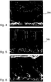
- Figure 4 shows a Cr-poor layer 36a with a cubic phase of the space group Fd3m.
- Figure 5 shows a Cr-rich hard material layer 36b having a hexagonal phase of space group R-3c.
- the hard material layer has a columnar, crystalline microstructure.
- Figure 6 shows by way of illustration a comparative example with a pure Al2O3 hard material layer on an (Al, Cr, Si) N adhesive layer.
- the Al2O3 layer has an amorphous appearance.
- the hard material layer 36 in FIG Fig. 2 was generated by constant conditions during the coating period.
- a multilayer structure can also be generated if the conditions on the substrate change during the coating period.
- Fig. 3 schematically shows such a multilayer layer structure.
- On the substrate 30 there is also an adhesive layer 32 and a transition layer 34.
- the coating over it alternately comprises layers 36a and 36b (in the example shown two each, of course, however, any numbers can be generated).
- the layers 36a and 36b are different in composition. These can be achieved, for example, by supplying different process gases during the coating period (for example alternating nitrogen / oxygen) or by different target placement.
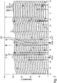
- Figure 7 shows XRD spectra of hard coatings of the type Al-Cr-Si-O. These layers were deposited on an Al-Cr-Si-N intermediate layer on a WC-Co hard metal. The process conditions were the same except for the composition of the targets.
- the XRD spectrum also shows phases of the interlayer and phases with tungsten. The latter are caused by the cemented carbide substrate.
- an Al-Cr-Si oxide layer having an Al-Cr-Si nitride adhesion layer and an Al-Cr-Si oxinitride transition layer is to be PVD-deposited.
- Applicant's CC800 system has four targets of Al-Si alloy plates with 10 at.% Silicon embedded in Cr plugs.
- the areal Cr content in the erosion trench is approx. 33%. All used targets were run in before the experiments.
- the substrates are heated to about 400 ° C.
- the cathodes are operated bipolarly between two cathodes each at a frequency of 250 kHz in pulse mode.
- the layer thickness is after 2.5 hours about 3.5 microns.
- the size of the grains of the layer is about 50-100 nm.
- the hardness of the layer produced is about 2400 HV.
- the XRD spectrum shows u.a. the gamma phase of an (Al, Cr) 2O3 or (Al, Cr, Si) 2O3 substitution mixed crystal.
- Example 1 Essentially, the same parameters are set as in Example 1, but the targets no longer contain silicon but consist of pure aluminum with Cr plugs. The parameters were slightly adjusted with respect to the changed targets. The coating time was chosen so as to give the same layer thickness as in Example 1.
- the hardness of the produced layer is about 2200 HV.
- a manually performed abrasion test in contrast to Example 1, there is a failure of the edges, since the layer is partially dissolved.
- the XRD shows no phases from the system Al-Cr-O.
- Example 1 Essentially the same parameters are set as in Example 1, but the targets consist only of aluminum. The parameters were slightly adjusted with respect to the changed targets. The coating time was chosen so as to give the same layer thickness as in Example 1. The hardness was only 1200 HV. Crystalline phases of Al2O3 were not or at most suggestively found.
- Example 1 shows a better adhesion in the Rockwell test.
- example 1 Essentially the same parameters as in example 1 are set. However, two of the four targets each consist of a titanium plate with aluminum plugs. Since only two of the four targets run at a time, the coating time must be extended accordingly. Initially, only the two TiAl targets are operated with nitrogen as the reactive gas until an approximately 2 ⁇ m thick TiAlN layer has formed.
- the magnetrons are then switched off with the TiAl targets and switched on with AlCrSi targets. Immediately thereafter, the inflow of nitrogen is suppressed while oxygen is admitted. An approximately 100 nm thick transition layer of AlCrSiNO is formed, on which an AlCrSiO layer then grows as in Example 1. At a total layer thickness of also 3.5 microns was the Process stopped: As far as measurement accuracy is concerned, the layer has the same good properties as the layer in Example 1.
- the substrate is coated with a hard material layer of CrAlSiO (N) by pulsed DC magnetron sputtering.
- the coating is deposited by means of two targets with a composition in the ratio Al: Cr: Si of 60: 35: 5 At%.
- a CrAlSiN layer of 1.7 ⁇ m thick is deposited under the following conditions.
- a 0.2 ⁇ m thick transition layer is created by a decrease in N2 flux to 60 ml with a simultaneous increase in O2 flow from 0 ml to 17 ml.
- a hard material layer with a thickness of 2.9 ⁇ m is applied under the following conditions: target power 3100 W, target voltage 350 V, total pressure 255 mPa, N2 flow 60 ml / min, Ar flow 240 ml / min, O2 flow 17 ml, substrate temperature 300 ° C. Since nitrogen is less reactive, relatively more nitrogen must be added.
- the nitrogen content in the hard material layer is 45 at.%.
- the atomic ratios of Al: Cr: Si are 57: 37: 6.
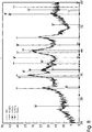
- Fig. 8 an XRD spectrum of the generated hard material layer is shown.
- the associated XRD spectrum shows peaks of crystalline Cr2O3 as well as gamma and kappa Al2O3.
- the existing Si does not show its own crystalline phases, but is present at the grain boundaries as amorphous Si or as an amorphous Si compound, for example as Si3N4.
- Other peaks are due to the hard metal substrate (WC).
- the hardness of the layer is 2800 HV.
- a layer sequence as in Example 4 is produced by means of HiPiMS, wherein the time-averaged electrical power at the targets is selected to be equal to Example 4.
- the average voltage is 650 V and the maximum power density before the target is 4 kW / cm 2 .
- the hardness is 3100 HV.
Landscapes
- Chemical & Material Sciences (AREA)
- Engineering & Computer Science (AREA)
- Organic Chemistry (AREA)
- Materials Engineering (AREA)
- Mechanical Engineering (AREA)
- Metallurgy (AREA)
- Chemical Kinetics & Catalysis (AREA)
- Inorganic Chemistry (AREA)
- Ceramic Engineering (AREA)
- Physics & Mathematics (AREA)
- Plasma & Fusion (AREA)
- Analytical Chemistry (AREA)
- Physical Vapour Deposition (AREA)
- Cutting Tools, Boring Holders, And Turrets (AREA)
Description
- Die Erfindung betrifft ein Schneidwerkzeug zum Zerspanen mit einem Substrat und einer auf dem Substrat aufgebrachten Hartstoffschicht sowie ein Verfahren zur Herstellung einer Hartstoffschicht.
- Zur Verbesserung der Eigenschaften ist es bekannt, die Oberfläche von Körpern zu beschichten. Beschichtete Körper umfassen ein Substratmaterial und eine oder mehrere darauf aufgebrachte Schichten. Insbesondere für Werkzeuge, beispielsweise Bohrer, Fräser oder Wendeschneidplatten ist es bekannt, auf einem Substrat-Material, beispielsweise HSSStahl oder Hartmetall, eine oder mehrere Schichten aufzubringen.
- Es sind verschiedene Materialien bzw. Materialsysteme aus verschiedenen Elementen bekannt, aus denen Hartstoffschichten gebildet werden können. Diese Schichten dienen besonders der Verbesserung der Härte, Warmhärte, Verschleissfestigkeit, Reibeigenschaften, der chemischen Beständigkeit und der Oxidationsbeständigkeit.
- Besonders in Hinblick auf die Oxidationsbeständigkeit haben sich Schichten aus Aluminiumoxid bewährt. Diese werden häufig mit der CVD-Technik aufgebracht. Beispielsweise in
US-A-4180400 ist die Abscheidung von kristallinem alphaAI2O3 mittels thermischem CVD beschrieben. Die CVD-Technik verwendet allerdings hohe Temperaturen, was zu einer entsprechenden Belastung der Substrate, und zu hohen Zugspannungen in der Schicht führt. Weiterer Nachteil ist u. A. die Verunreinigung mit Halogenen. Da Stahlwerkstoffe bei den hohen Temperaturen weich werden, werden CVDBeschichtungen für Werkzeuge und Verschleissteile vorwiegend auf Hartmetall aufgebracht. Doch selbst diese relativ temperaturbeständigen Substrate werden beim CVD durch eta-Phasenbildung in der Oberfläche versprödet. Überdies führen die hohen Temperaturen auf Grund der unterschiedlichen Wärmeausdehnung zu den bei CVD bekannten schädlichen hohen Zugspannungen. Die Schichten weisen deshalb in der Regel ein Rissnetzwerk auf, das den Schichtverbund schwächt und den Korrosionsschutz der Schicht verschlechtert. - Eine alternative Beschichtungstechnik sind insbesondere plasmagestützte PVD-Verfahren. Bekannt sind hier einerseits PVD-Verfahren mittels Lichtbogenverdampfens (Are-Verfahren), bei denen das metallische Element über die schmelzflüssige Phase verdampft wird und andererseits das Magnetronzerstäuben, bei dem Targets aus dem zu zerstäubenden Material als Kathode einer elektrischen Niederdruckglimmentladung eingesetzt werden, wobei Ionen des Plasmas die Targets zerstäuben.
- Bei der Beschichtung mit Oxidschichten gibt es jedoch erhebliche Einschränkungen bei der verwendeten Beschichtungstechnik, da diese Schichten i.d.R. elektrisch isolierend sind.
- Es fehlt nicht an Versuchen, kristalline Phasen des Aluminiumoxids mittels PVD aufzubringen. Dabei lässt sich bei den verwendeten niedrigen Temperaturen, wie beschrieben in
US-A-4790920 ,US-A-5693417 undUS-A-6210726 , vor allem die kristalline gamma-Phase erzeugen. - In der
EP-A-1614655 sind eine Hartstoffbeschichtung und ein PVD-Herstellungsverfahren hierfür beschrieben. Die Hartstoffbeschichtung wird mit Hilfe eines PVD-Verfahrens aufgebracht, bei dem einerseits das Material eines AIP-Targets (Arc discharge Ion Plating) mit Hilfe von Lichtbogenverdampfen und andererseits das Material eines MS-Targets (Magentron Sputtering) mit Magnetronzerstäben in ein Plasma überführt wird. Dabei werden Sauerstoff-haltige Prozessgase zugeführt. Die Schicht umfasst die Metall-Elemente Si und mindestens ein weiteres Element ausgewählt aus den Übergangsmetallen der Gruppen 4a, 4a und 6a des Periodensystems, Al und B. Weiter umfasst die Beschichtung nicht-metallische Elemente ausgewählt aus C, N und O. Sauerstoff wird zur Verbesserung der Schmierung eingesetzt, allerdings ist der Anteil des Sauerstoffs an den nicht-metallischen Elementen auf 5 At.-% beschränkt. - In der
EP-A-701982 - In der
EP-A1422311 werden Hartstoffschichten beschrieben, die mittels Lichtbogenverdampfens hergestellt werden. Die Schicht beinhaltet u. a. die metallischen Elemente Al, Cr, und Si sowie die nichtmetallischen Elemente N, B, C und O. Es sind zahlreiche Kombinationen mit den genannten Elementen genannt, jedoch geht der Sauerstoffanteil unter den nichtmetallischen Elementen nicht über 25 At. % hinaus. - In Yamamoto et al: "Structural and mechanical property of Si incorporated (Ti,Cr,Al)N coatings deposited by arc ion plating process" SURFACE AND COATINGS TECHNOLOGY, ELSEVIER, AMSTERDAM, NL, Bd. 200, Nr. 5 - 6, 21. November 2005 (2005-11-21), Seiten 1383 - 1390, XP005173157, ISSN: 0257-8972 werden (Ti, Cr, Al, Si)N-Beschichtungen auf WC-Co Wendeschneidplatten untersucht. Die Substrate werden zunächst einem Ätzverfahren mit Argonionen unterworfen und dann durch Lichtbogen-Ionenplattieren mit Hilfe einer plasmaunterstützten Kathode beschichtet. Erwähnte, hierbei erzielte Zusammensetzungen sind (Ti0.2, Cr0.2, Al0.55, Si0.05) N, (Ti0.15, Cr0.2, Al0.6, Si0.05)N, (Ti0.2, Cr0.23, Al0.53, Si0.04)N, (Ti0.14, Cr0.22, Al0.59, Si0.05)N. In einer auf die Oxidationsbeständigkeit gerichteten Untersuchung werden beschichtete Substrate in Luft bei 1000°C für 30 Minuten wärmebehandelt, wobei es zur Oxidation kommt. In einem AES-Tiefenprofil variiert hierbei der atomare Anteil von Sauerstoff in der so behandelten Schicht zwischen 60 und 0 at.-%.
- In der
WO 99/29920 A - In Wang et al: "Improvement of the interfacial integrity of (Ti,Al)N hard coatings deposited on high speed steel cutting tools" SURFACE AND COATINGS TECHNOLOGY ELSEVIER SWITZERLAND, Bd. 120 - 121, November 1999 (1999-11), Seiten 388 - 394, SP002444203 ISSN: 0257-8972 wird eine (Ti, Al)N-Beschichtung auf HSS-Werkzeugen untersucht. Um Haftungsproblemen zu begegnen, die aufgrund der großen Diskrepanz der thermischen Eigenschaften auftreten, wird eine dünne TiN-Haftschicht von 0.2 µm aufgebracht.
- In der
DE 103 60 482 A1 ist ein mit einer Hartstoffschicht versehenes Substrat, beispielsweise Hartmetall, HSS-Stahl, Cermet oder dergleichen beschrieben. Die Beschichtung besteht aus mehreren Schichten, von denen die äußerste Schicht kubisches Bornitrid ist. Um eine gute Haftung auf dem Substrat zu erreichen, ist direkt auf dem Substrat eine Haftschicht aufgebracht, die aus einem oder mehreren Metallen ausgewählt aus der Gruppe bestehend aus den Elementen in den Gruppen 4a, 5a und 6a des Periodensystems oder ein Nitrid und/oder Karbonitrid eines oder mehrerer dieser Metalle umfaßt. Zwischen der Haftschicht und der Oberflächenschicht befindet sich eine Gradientenschicht, in der sich der Gehalt an B und C von der Haftschicht zur Oberflächenschicht hin kontinuierlich oder schrittweise ändert. Die beschriebenen Schichten werden in einem PVD-Verfahren mittels nicht ausgeglichenem Magnetron-Sputtern erzeugt, wobei ein Target die genannten Metalle und ein weiteres Target mindestens B und C enthält. - In der
WO 03/085152 A2 - Es ist Aufgabe der Erfindung, ein Werkzeug zum Zerspanen sowie ein Verfahren zur Herstellung eines beschichteten Körpers, vorzuschlagen, bei denen Schichten mit besonders günstigen Eigenschaften Verwendung finden.
- Diese Aufgabe wird gelöst durch ein Schneidwerkzeug nach Anspruch 1 und ein Verfahren nach Anspruch 15. Abhängige Ansprüche beziehen sich auf bevorzugte Ausführungsformen der Erfindung.
- Bei dem erfindungsgemäßen Schneidwerkzeug ist die Hartstoffschicht mittels Magnetronzerstäubens abgeschieden und enthält die metallischen Elemente Al, Cr und Si sowie nichtmetallische Elemente ausgewählt aus der Gruppe B, C, N, O. Der atomare Anteil von Sauerstoff an den nichtmetallischen Elementen ist größer als 30%.
- Ein derartiger Körper hat besonders gute Oberflächeneigenschaften für die Verwendung als Schneidwerkzeug zum Zerspanen. Durch den hohen Sauerstoffanteil ergibt sich eine sehr gute Oxidationsbeständigkeit der Schicht. Ein zu geringer Sauerstoffanteil führt hingegen zu einer zu geringen Oxidationsbeständigkeit.
- Neben Sauerstoff können in der Hartstoffschicht weitere nichtmetallische Elemente vorhanden sein, bevorzugt aus der Gruppe B, C, N. Bezüglich der nichtmetallischen Elemente in der Schicht werden in dieser Schrift die relativen atomaren Anteile der nichtmetallischen Elemente B,C,N,o untereinander angegeben und mit der Einheit Atomprozent oder At.% versehen. Die nichtmetallischen Elemente sind bevorzugt weit überwiegend (i. e. mehr als 80 At.%), bevorzugt zu nahezu 100 At.%, chemisch an die metallischen Elemente gebunden.
- Bevorzugt ist der atomare Anteil von Sauerstoff an den nichtmetallischen Elementen größer als 70%.
- Bei den At.% Angaben ist zu berücksichtigen, daß die Schichten stets z. B. durch den Herstellungsprozeß bedingte zusätzliche Elemente enthalten können, die als Verunreinigungen wirken. Bei PVD-Sputterschichten sind die Schichten in der Regel mit dem als Prozeßgas verwendeten Edelgas verunreinigt. Die Verunreinigung z. B. mit Argon liegt meist bei nicht mehr als 3 At.%. Ein typischer Wert ist 1-2 At.%. Das ggf. vorhandene Sputtergas Krypton wird nicht oder wesentlich schwächer eingebaut.
- Dagegen sind die im PVD-Verfahren erzeugten Schichten im Gegensatz zu CVD-Schichten frei von Halogeniden und/oder Wasserstoff.
- Die Verunreinigung durch Metalle ist beim Sputtern in der Regel gering, wenn die Kammer und die Haltersysteme schon mit dem Beschichtungsmaterial belegt sind und die Targets eine hohe Reinheit besitzen.
- In einer besonders bevorzugten Ausführung beträgt der Sauerstoffgehalt der Hartstoffschicht nahezu 100% At.%, d.h. bis auf ggfs. vorhandene Verunreinigungen ist an nichtmetallischen Elementen ausschließlich Sauerstoff in der Schicht enthalten. Durch sehr hohe Sauerstoffgehalte ergibt sich eine hervorragende Oxidationsbeständigkeit.
- In Fällen, in denen zwar eine erhöhte Oxidationsbeständigkeit, aber zusätzlich eine hohe Härte erzielt werden soll, können alternativ die nichtmetallischen Elemente auch so gewählt werden, dass neben einem hohen Sauerstoffanteil (30 At.% und mehr) ein Stickstoffanteil vorhanden ist. Wie sich herausgestellt hat, lassen sich besonders harte Schichten bis zu 3500 HV erzielen, wenn in der Hartstoffschicht im Wesentlichen (d.h. neben üblichen Verunreinigungen) als Nichtmetalle nur Sauerstoff und Stickstoff vorliegen, wobei der atomare Anteil von Stickstoff im Verhältnis zur Summe von Sauerstoff und Stickstoff größer gleich 10 At.% und kleiner gleich 70 At.% ist. Weiter bevorzugt ist der Stickstoffanteil größer gleich 30 At.%, besonders bevorzugt größer gleich 50 At.%. Die Hartstoffschichten können weitere Metalle, bevorzugt Elemente aus den Gruppen 4 bis 6 des Periodensystems (nach IUPAC 1988) enthalten. Die Beimengung anderer metallischer (und nichtmetallischer) Elemente sollte allerdings in der Menge begrenzt sein, da hierdurch Härte, Dichte, Schichthaftung, Schichtstruktur und Schichtspannungen ungünstig beeinflusst werden können. Metallische Elemente, die keine mechanisch stabilen Oxide ausbilden, sollten in der Schicht nur in beschränktem Maße vorhanden sein sollten. Denn durch die Verwendung von Sauerstoff als Reaktivgas entstehen Oxide dieser Elemente in der Schicht, die bei abrasiver Belastung die Erosion der Schicht fördern können. Beispielsweise sind Titanoxide den Schichteigenschaften in der beschriebenen Weise abträglich.
- Durch geeignete Auswahl der Mengenverhältnisse der metallischen Elemente lassen sich die Eigenschaften günstig beeinflussen. Die Prozentangaben in Atomprozent (At.%) sind in dieser Schrift, wenn nicht anders gesagt, die relativen Anteile der metallischen Elemente Al, Cr und Si untereinander.
- An metallischen Elementen enthält die Hartstoffschicht bevorzugt überwiegend (d.h. zu mehr als 50 At.%) Elemente der Gruppe Al, Cr, Si. Weiter bevorzugt ist der atomare Anteil der metallischen Elemente dieser Gruppe größer als 80 At.%. Besonders bevorzugt ist der Anteil nahezu 100 At.%, d.h. daß bis auf ggfs. vorhandene Verunreinigungen sind an metallischen Elementen ausschließlich Al, Cr und Si in der Schicht enthalten. Ein wesentlicher Grund für die Vorteile des erfindungsgemäßen Körpers ist, dass die Elemente Al, Cr, Si alle stabile Oxide und Nitride bilden. Wie noch beschrieben wird, können Nitride bevorzugt für Haft- oder Übergangsschichten verwendet werden um eine gute Substrathaftung zu erzielen.
- Weitere Verbindungen und Oxide können zwar bspw. als Festschmierstoffe den Zerspanprozess verbessern. In der eigentlichen Hartstoffschicht ist ihr Anteil aber wie dargestellt zu begrenzen. Sie können bevorzugt als separate, obere Funktionsschichten oder als Zwischenschichten in einer Multilayer-Struktur vorgesehen sein.
- Bevorzugt beinhaltet die Hartstoffschicht Oxide und/oder Mischoxide der Elemente Al, Si und Cr. In zahlreichen Versuchen hat sich herausgestellt, dass Hartstoffschichten, die eine Kombination aus Oxiden und/oder Mischoxiden der Elemente Al, Cr und Si enthalten besonders günstige Schichteigenschaften hinsichtlich Härte, Haftung, Zähigkeit und Oxidationsbeständigkeit aufweisen.
- Gemäß einer Weiterbildung der Erfindung umfasst die Hartstoffschicht die metallischen Elemente Al, Cr und Si im Verhältnis (in At.% nur der metallischen Elemente) x zu y zu z. Bevorzugt ist eine Zusammensetzung mit einem Cr-Anteil y zwischen 1% und 70% und einem Si-Anteil z zwischen 0,1% und 20%, Rest Al. Weiter bevorzugt ist y zwischen 4% und 60%, z zwischen 0,5% und 10%, Rest Al. Besonders bevorzugt ist y zwischen 10% und 50%, z zwischen 1% und 5%, Rest Al. Außerhalb der beanspruchten Bereiche nehmen vor allem Härte und Haftung der Schichten ab, so dass keine Vorteile bei Verschleißanwendungen zu erwarten sind.
- Die Hartstoffschicht kann einphasig sein, bspw. in der gamma-Phase des Al2O3 vorliegen. Alternativ kann die Hartstoffschicht mehrphasig sein. Die Hartstoffschicht kann sich bspw. zusammensetzen aus Al2O3 in der gamma-, alpha-, oder kappa-Phase, aus Cr2O3, SiO2, sowie aus Substitutionsmischkristallen der Elemente Al-Cr-Si-O.
- Bei Anwesenheit von Stickstoff liegen auch Phasen im System Al-Cr-Si-O-N vor, bspw. Si3N4, AlN, CrN und Cr2N. Diese können als amorphe Verbindungen vorliegen, insbesondere die Si-Verbindungen.
- Bevorzugt sind in der Hartstoffschicht kristalline Phasen und/oder Mischphasen im System Al-Cr-Si-O enthalten, im Besonderen in der Zusammensetzung (Al,Cr,Si)2O3.
- Es können sich sowohl kubische Phasen der Raumgruppe Fd3m als auch hexagonale Phasen der Raumgruppe R-3c ausbilden. Die hexagonalen Phasen bilden sich vor allem bei Cr-reichen Zusammensetzungen (bspw. über 50 At.% Cr). Die kubische Phase kann sich schon bei geringen Cr-Gehalten deutlich unter 5 At.% bilden. Zur kubischen Phase gehören auch Substitutionsmischkristalle des gamma-Al2O3, in denen Al durch andere Elemente ersetzt ist. Werden derartige Materialien mittels Röntgenbeugung untersucht, sind in den XRD-Spektren häufig nur Phasen des Systems (Al,Cr)2O3 zu erkennen. Offenbar fördert ein gewisser Si-Anteil die Bildung dieser Phasen, denn die Phasen treten nur auf, wenn auch Si in der Schicht enthalten ist. Andererseits sollte der Si-Anteil bevorzugt begrenzt bleiben, da es sonst zu einer Verminderung der Schichthaftung kommt.
- Bei dem erfindungsgemäßen Verfahren wird die Schicht mittels Magnetronzerstäubens aufgebracht. Beim Magnetronzerstäuben erfolgt unmittelbar aus der festen Phase das Zerstäuben der Targets. Im Gegensatz hierzu wird bei PVD -Verfahren mittels Lichtbogenverdampfens (Arc-Verfahren) das metallische Element über die schmelzflüssige Phase verdampft. Das Magnetronzerstäuben vermeidet dabei die hieraus resultierenden Nachteile wie den Einbau von aufgeschmolzenen Kleinstpartikeln, sog. droplets. Vor allem aber hat sich bezüglich Arc-Verfahren herausgestellt, dass das Einbringen von Sauerstoff wegen einer sofortigen Reaktion des Sauerstoffs mit dem aufgeschmolzenen Material problematisch sein kann. Gleiches gilt für das thermische Aufschmelzen von Metallen aus Tiegeln oder mittels Elektronenstrahls.
- Beim Magnetronzerstäuben, bei dem Targets aus dem zu zerstäubenden Material als Kathode einer elektrischen Niederdruckglimmentladung geschaltet sind, zerstäuben Ionen des Plasmas das Target, ohne dass die Schmelztemperatur des Targetmaterials erreicht werden muss. Zur Erhöhung der Plasmadichte und der Abtragsraten befindet sich hinter dem Target ein Magnetsystem.
- Die Temperaturen können - auch bspw. durch Kühlung des Targets - niedrig gehalten werden. Hierdurch bleiben Reaktionen des Targetmaterials mir den Reaktivgasen gering. Deshalb ist das Magnetronverfahren besonders gut geeignet, auch Oxide, im besonderen Aluminiumoxid, bei niedrigen Temperaturen abzuscheiden. Die Temperaturen bleiben dabei bevorzugt unter 500°C.
- Durch ein zusätzliches negatives Potential am Substrattisch kann das Substrat während der Beschichtung mit Ionen beschossen werden. Dies verbessert in der Regel die Qualität der Schichteigenschaften wie Dichte, Haftung, Härte, Porosität u.a. Durch den Ionenbeschuss wird ferner die Schichtbildung durch Reaktion mit dem vorhandenen Reaktivgas, im vorliegenden Fall bevorzugt Sauerstoff, gefördert.
- Die Targets werden beim Magnetronzerstäuben nach kurzer Einfahrzeit gleichmäßig entsprechend ihren Materialanteilen abgetragen. Die Targets können aus Legierungen oder Verbindungen der Beschichtungsmaterialien bestehen. Ferner können die Targets aus unterschiedlichen Materialsegmenten zusammengesetzt sein. Bei Verwendung mehrerer Magnetrons können diese ferner mit unterschiedlichen Targetmaterialien bestückt werden. Im Prinzip können Beschichtungen mit allen Metallen und Metalloiden hergestellt werden.
- Sollen die Temperaturen sehr niedrig gewählt werden und soll ein hoher Anteil an kristallinen Phasen in der Hartstoffschicht vorliegen, können Mittel zur Zusatzionisation, wie z.B. Hohlelektroden eingesetzt werden.
- Für die Magnetronabscheidung von Oxiden kann man, statt herkömmliche Gleichstromplasmen zu verwenden, die Elektroden mit Wechselspannung betreiben. Die Druckschriften
US-A-4046659 undUS-A-4013532 sowieDD 252205 - Gemäß einer Weiterbildung der Erfindung wird das so genannte "hochleistungsgepulste Magnetronzerstäuben" (englisch "High Power Impuls Magnetron Sputtering" oder kurz HIPIMS) eingesetzt. Dieses ist gekennzeichnet durch kurze Pulse von sehr hoher Leistung. Die Pulse können so hohe Leistungen aufweisen, daß von den Targets eine Leistungsdichte von 500-5000 W/cm2 erreicht werden, die aber nur für maximal 20% der Zykluszeit anliegen. Aufgrund des sehr niedrigen Tastverhältnisses (An-Zeit zu Aus-Zeit) liegt die Leistung im zeitlichen Mittel dann wieder im selben Bereich wie bei herkömmlichen DC- oder Puls-PVD Verfahren. Es ergibt sich aber eine nahezu vollständige Ionisation vor dem Target. Wie sich für die erfindungsgemäßen Schichten herausgestellt hat, werden durch HIPIMS besonders dichte und harte Schichten erzeugt.
- Gemäß einer Weiterbildung der Erfindung ist zwischen dem Substrat, d.h. dem Material des Grundkörpers, und der Hartstoffschicht eine Haftschicht angeordnet. Hierdurch kann die Schichthaftung auf dem Substrat entscheidend verbessert werden. Die jeweilige Zusammensetzung und Dicke der Haftschicht sollte abhängig vom jeweiligen Substratmaterial gewählt werden. Hier spielen die chemische Bindung, die Ausdehnungskoeffizienten und Gitterparameter von Substrat und Schicht eine Rolle.
- Die Haftschicht setzt sich bevorzugt aus einer Auswahl von Elementen aus der Menge Al, Si und Elementen der Gruppen 4 bis 6 des Periodensystems nach IUPAC (1988), sowie aus einer Auswahl von nichtmetallischen Elementen aus der Gruppe B, C, N, O zusammen. Bei den metallischen Anteilen der Haftschicht sind die Elemente Ti, Al, Si, Cr bevorzugt. In der Haftschicht ist der Sauerstoffanteil geringer als in der Hartstoffschicht. Die Haftschicht ist bevorzugt direkt auf dem Substratmaterial aufgetragen.
- Bevorzugt sind die metallischen Elemente der Haftschicht aus der Gruppe der metallischen Elemente der Hartstoffschicht ausgewählt. Weiter bevorzugt ist in der Haftschicht ein atomarer Anteil von N an den nichtmetallischen Elementen vorhanden, der größer ist als in der Hartstoffschicht. Der Anteil an N ist besonders bevorzugt im Wesentlichen bei 100% At.%, d.h. dass es sich - bis auf Verunreinigungen - um eine reine Nitridschicht handelt.
- Bevorzugt ist eine Kombination von Hartstoffschicht und Haftschicht, in der die Hartstoffschicht im Wesentlichen (d.h. bis auf Verunreinigungen an metallischen oder nichtmetallischen Elementen) aus Al, Cr, Si und O besteht und die Haftschicht im Wesentlichen aus Al, Cr, Si und N, insbesondere aus kristallinem (Al,Cr,Si)N. Alternativ kann die Haftschicht auch aus kristallinem (Ti, Al)N bestehen und die Hartstoffschicht aus AlCrSiO.
- Die Hartstoffschicht kann zwar direkt auf die Haftschicht folgen. Gemäß einer Weiterbildung der Erfindung ist aber zwischen der Haftschicht und der Hartstoffschicht bevorzugt eine Übergangsschicht angeordnet. Diese setzt sich aus einer Auswahl der Elemente zusammen, die die Hartstoff- und Haftschicht bilden. So findet ein Übergang von der Zusammensetzung der Haftschicht zur Zusammensetzung Hartstoffschicht statt.
- Es hat sich besonders bewährt, für Haft- und Übergangsschichten die gleiche Zusammensetzung an metallischen Elementen, wie in der Hartstoffschicht zu wählen und als nicht-metallisches Element vorwiegend N zu verwenden. Dies gilt besonders für Hartmetall-Substrate.
- Bevorzugt ändert sich in der Übergangsschicht in der Richtung quer zur Schicht wenigstens ein Element in seiner Konzentration kontinuierlich, so dass die Konzentration des Elements an der Grenze zur Hartstoffschicht im wesentlichen gleich der Konzentration in der Hartstoffschicht ist und an der Grenze zur Haftschicht im wesentlichen gleich der Konzentration in der Haftschicht ist. Bei dem variierenden Element handelt es sich bevorzugt um N, O, oder um beide dieser Elemente.
- Es ist eine Vielzahl von möglichen Schichtfolgen denkbar. Im einfachsten Fall besteht der Körper nur aus dem Substratmaterial mit einer in ihrer Zusammensetzung konstanten Hartstoffschicht. Bevorzugt sind wie oben beschrieben jeweils mindestens eine Haft- und Zwischenschicht zwischen Substrat und Hartstoffschicht. Da im Einsatz bei starkem Verschleiß der Hartstoffschicht auch Haft- und ggfs. Übergangsschicht teilweise freigelegt werden können, kommt es auch auch bei diesen Schichten auf die Eigenschaften zum Schutz des Substrates an. Die Dicke des gesamten Schichtsystems beträgt bspw. 1-10, bevorzugt 2-8, besonders bevorzugt 3-5 µm. Falls eine Haftschicht vorhanden ist, umfaßt diese bspw. 10 - 70 %, bevorzugt 25 - 60 %, besonders bevorzugt mindestens 35 % des Schichtsystems. Die Dicke der Übergangsschicht kann in derselben Größenordnung liegen wie die der Hartstoffschicht. Die Übergangsschicht ist aber bevorzugt dünner, und liegt weiter bevorzugt im Bereich von 2-200 nm.
- Der Körper kann allerdings auch beispielsweise eine Mehrlagenbeschichtung (multilayer) aufweisen. Diese kann Schichten mit Zusammensetzungen wie vorstehend als Haft- und Übergangsschichten beschrieben im Wechsel mit den beschriebenen Hartstoffschichten umfassen. Ebenso ist eine Folge von Hartstoffschichten möglich, wobei sich die Zusammensetzung der metallischen Elemente im Wesentlichen periodisch ändert. Beispielsweise sind Mehrlagenbeschichtungen vorteilhaft, bei deren Herstellung die Reaktivgase N2 und O2 periodisch und gegenläufig variiert werden um entsprechende periodische Variationen im Schichtmaterial zu erzeugen. Andere Mehrlagenbeschichtungen ergeben sich, wenn Targets unterschiedlicher Zusammensetzung an- und abgeschaltet bzw. in der Leistung variiert werden. Mehrlagenbeschichtungen mit Einzelschichtdicken im Nanometerbereich ergeben sich, wenn die Substrate auf Drehtischen periodisch an Targets mit unterschiedlicher Zusammensetzung vorbeigeführt werden.
- Nachfolgend werden Ausführungsformen der Erfindung in Hinblick auf die beigefügten Zeichnungen näher beschrieben. In den Zeichnungen zeigen
- Fig. 1
- in symbolischer Darstellung ein Beispiel von Bestandteilen einer PVD-Beschichtungsanlage,
- Fig. 2
- in symbolischer Darstellung ein erstes Ausführungsbeispiel eines beschichteten Körpers mit einer Haftschicht, einer Übergangsschicht und einer Hartstoffschicht,
- Fig. 3
- in symbolischer Darstellung ein zweites Ausführungsbeispiel eines beschichteten Körpers mit einer Multilayer-Struktur,
- Fig. 4
- eine Fotografie eines Schliffs einer ersten Ausführungsform einer (Al,Cr,Si)2O3-Hartstoffschicht,
- Fig. 5
- eine Fotografie eines Schliffs einer zweiten Ausführungsform einer (Al,Cr,Si)2O3-Hartstoffschicht,
- Fig. 6
- eine Fotografie eines Schliffs einer Al2O3 Hartstoffschicht auf einer (Al,Cr,Si)N Haftschicht als Vergleichsbeispiel,
- Fig. 7
- in Diagrammform XRD-Spektren von Hartstoffschichten der Art Al-Cr-Si-O,
- Fig. 8
- in Diagrammform ein XRD-Spektrum einer Hartstoffschicht der Art Al-Cr-Si-O-N.
-
Fig.1 zeigt in symbolischer Darstellung ein Beispiel von Bestandteilen einer PVD-Beschichtungsanlage 10 zur Durchführung von Magnetron-Sputterverfahren. Derartige Anlagen sowie die Arbeitsweise zum Aufbringen von Beschichtungen sind dem Fachmann per se bekannt, so dass hier nur eine kurze eine generelle Erläuterung der Anlage 10 erfolgen soll. Auf die speziellen Betriebsarten zur Erzeugung von erfindungsgemäßen Schichten soll später eingegangen werden. - In einer Beschichtungskammer 12 unter niedrigem Druck sind eine Anzahl von, im dargestellten Beispiel vier Kathoden 16 sowie ein Substrat-Halter 18 (bestehend aus einem rotierenden Substrattisch 20 mit einer Anzahl von ihrerseits drehenden Halte-Aufbauten 22) angeordnet. Über einen Gaseinlass 24 werden die Prozessgase, bestehend aus einen Inertgas, bspw. Argon, und Reaktivgasen bspw. N2, O2 zugeleitet.
- Die Kathoden 16 sind als Magnetron-Kathoden ausgebildet und weisen jeweils Targets auf, die als Platten aus dem zu zerstäubendem Material ausgebildet sind. Für das System Al-Cr-Si kann beispielsweise das Cr oder Si in Form von Stopfen in Bohrungen einer Aluminiumplatte eingesetzt werden und/oder Verbund- oder Legierungstargets aus den Materialien verwendet werden. Sind wie dargestellt mehrere Magnetrontargets vorhanden, dann kann beispielsweise jedes Magnetron eine Komponente zerstäuben und die Konzentrationen lassen sich so über die elektrische Leistung, die den Magnetrons zugeführt wird, besonders gut einstellen.
- Wie dem Fachmann bekannt ist, entspricht die Zusammensetzung der Schicht beim Magnetronzerstäuben in etwa der Zusammensetzung der Targets, wenn diese zuvor eingefahren wurden. Auf der Targetseite ist dabei die Zusammensetzung im Bereich des durch die Magnetfelder des Magnetrons erzeugten Erosionsgrabens ausschlaggebend.
- Im Betrieb der Anlage 10 liegt eine Spannung von beispielsweise etwa 500 Volt an den Kathoden 16 an. Zur Vermeidung von Aufladungen bei hohem Sauerstoffgehalt können die Kathoden 16 einzeln oder gegeneinander gepulst werden. Ionen des Arbeitsgases werden wechselweise zwischen jeweils zwei Targets beschleunigt und zerstäuben diese. Zusätzlich wird als reaktives Gas gasförmiger Sauerstoff oder Stickstoff durch den Gaseinlass zugeführt. Unter dem Einfluss der elektrischen und magnetischen Felder im Bereich vor den Kathoden 16 kommt es zur Ausbildung einer Beschichtungsatmosphäre in Form eines Plasmas. Die Beschichtungsatmosphäre enthält die zugeführten gasförmigen Bestandteile sowie die zerstäubten Bestandteile der Targets.
- Alternativ kann die Beschichtungsanlage auch zur Ausführung des HIPIMS-Beschichtungsverfahrens ausgebildet sein. Dabei werden die Targets mit kurzzeitigen Pulsen hoher Leistung, allerdings bei niedrigem Tastverhältnis betrieben. Die Grundlagen des HIPIMS finden sich u.a. bei Kouznetsov, et al., "A Novel Pulsed Magnetron Sputter Technique Utilizing Very High Target Power Densities" in Surface and Coatings Technology, 1999, pp. 290-293, vol. 122. Die Beschichtungsanlage verfügt in diesem Fall über spezielle, für HIPIMS geeignete Leistungsversorgungen, wie bspw. beschrieben in
US-A-6296742 . Zusätzlich können, wie beschrieben inEP-A-1609882 , verschiedene Möglichkeiten genutzt werden, die Ionen nach dem Puls auf die Substrate zu lenken. - Die jeweilige Zusammensetzung der Beschichtungsatmosphäre ist hierbei von den Zerstäubungsraten der Targetmaterialien sowie vom eingestellten Gasfluss abhängig. Sie kann beeinflusst werden durch geeignete Wahl des Materials der Targets (freie Oberfläche der jeweiligen Targetmaterialien unter Berücksichtigung der Zerstäubungsrate), aber auch durch unterschiedliche Zugabe gasförmiger Bestandteile. Beispielsweise ist bekannt, dass sich bei Sauerstoffzufluss eine sog. "Vergiftung" (d. h. Bildung eines Oxids bereits auf dem festen Targetmaterial) eines Targets aus Al ergibt. Da die Zerstäubungsrate auch vom Grad der Vergiftung abhängt (bei vergifteten Targets kommt es zu einem dramatischen Rückgang der Sputterrate) kann so durch Einstellung des Zuflusses eines gasförmigen Bestandteils (hier: O2) auch der Al-Anteil der Beschichtungsatmosphäre gezielt eingestellt werden.
- Die Elemente der Beschichtungsatmosphäre lagern sich auf den Substraten, d. h. auf am Substrat-Halter 18 angebrachten Werkstücken wie Bohrer, Wendeschneidplatten etc., ab. Hierbei wird zwischen den Substraten und dem Plasma eine Potentialdifferenz erzeugt, beispielsweise durch eine Spannungsquelle zwischen dem Substrat-Halter 18 und der Wandung der Kammer 12. Aufgrund dieser Bias-Spannung kommt es auch auf dem Substrat zu einem Bombardement mit Ionen des Arbeitsgases, was zu einer höheren Verdichtung der Schicht und zu einem höheren Energieeintrag während der Schichtbildung führt. So können sich trotz niedriger Substrattemperaturen kristalline Phasen ausbilden.
- Das beschriebene Ionensputtern sowie verschiedene andere PVD-Beschichtungstechniken sind dem Fachmann grundsätzlich bekannt, so dass er in der Lage ist, mit den hier gegebenen Informationen auf einem Substrat eine Schicht aus den Elementen eines jeweils gewählten Systems abzuscheiden und dabei die Parameter des Verfahrens, beispielsweise Zusammensetzung der Beschichtungsatmosphäre, Substrattemperatur, Leistung der Kathoden, Bias-Spannung usw. so einzustellen, dass ein Schichtaufbau mit jeweils gewünschter Schichtrate und -struktur erfolgt.
- Zur Erzeugung von Schichten die Ausführungsformen der Erfindung darstellen wird wie folgt vorgegangen:
- Als Werkstücke werden Körper, insbesondere Werkzeug-Grundkörper verwendet, die aus dem gewählten Substratmaterial, beispielsweise Werkzeugstahl (z.B. HSS-Stahl) oder Hartmetall (bspw. WC-Co Hartmetall) bestehen. Diese werden an den Substrat-Haltern 18 angebracht. Es erfolgt dann in an sich bekannter Weise eine Vorbereitung des Substrats durch Ionenbeschuß. Hierfür wird ohne elektrische Leistung an den Targets und unter Zufuhr nur eines Edelgases (Argon) ein Plasma in der Kammer 12 erzeugt und eine hohe Bias-Spannung zwischen Plasma und den Substraten angelegt.
- Im folgenden Beschichtungsschritt wird das Material der Targets zerstäubt und zusätzlich zum Edelgas auch ein Reaktivgas zugeführt, so dass die entsprechenden Materialien sich aus dem Plasma auf dem Substrat ablagern.
- Zunächst wird auf dem Substrat eine Haftschicht erzeugt. Hierbei können die Targets wie beschrieben jeweils paarweise wechselseitig elektrisch gepulst werden. Als Reaktivgas wird Stickstoff mit zugeführt, so dass sich auf dem Substart eine Schicht ablagert. In einem bevorzugten Beispiel ist dies eine (Al, Cr, Si)-N Schicht.
- Sobald die gewünschte Schichtdicke der Haftschicht erreicht ist beginnt eine Übergangsphase, in der auf die Haftschicht eine Übergangsschicht aufgebracht wird. Hierfür wird bei unveränderter Ansteuerung der Targets die Zusammensetzung des Prozessgases so verändert, dass über die Dauer der Übergangsphase der StickstoffAnteil zugunsten eines Sauerstoff-Anteils kontinuierlich abgesenkt wird. Zum Ende der Übergangsphase erfolgt entweder zur Erzeugung reiner Oxid-Schichten keine weitere Stickstoff-Zufuhr mehr, oder die Stickstoffzufuhr wird auf einem niedrigen Niveau beibehalten.
- Danach wird das Verfahren mit dem Aufbringen einer Al-Cr-Si-Oxidschicht (ggfs. auch - in geringem Anteil - als Nitridschicht) fortgesetzt. Hier wird ausschließlich oder wenigstens überwiegend Sauerstoff als Reaktivgas zugeführt. Nach Erreichen der gewünschten Schichtdicke wird der Prozeß beendet.
-
Fig. 2 zeigt schematisch den entstandenen Schichtaufbau. Auf dem Substrat 30 befindet sich eine Haftschicht 32, deren Zusammensetzung abhängt von den während ihrer Aufbringung im Plasma befindlichen Elementen (d.h. Reaktivgas und zerstäubte Targets). Die Dicke der Haftschicht hängt von der gewählten Beschichtungsdauer mit den entsprechenden Bedingungen ab. Auf der Haftschicht folgt eine gradierte Übergangsschicht 34, bei der Dicke und Zusammensetzung wie oben beschrieben gewählt werden können. An die Übergangsschicht schließt sich die Hartstoffschicht 36 an. -
Fig.4 und 5 zeigen Fotos von Schliffen beschichteter Körper mit (Al,Cr,Si)2O3-Hartstoffschichten 36a, 36b, die unter gleichen Bedingungen auf der gleichen Haftschicht abgeschieden wurden. Lediglich die Zusammensetzung der Targets war verändert. Die Hartstoffschichten enthalten einige Atomprozente Si und zeigen eine kristalline Mikrostruktur. -
Fig.4 zeigt eine Cr-arme Schicht 36a mit einer kubischen Phase der Raumgruppe Fd3m. -
Fig.5 zeigt eine Cr-reiche Hartstoffschicht 36b mit einer hexagonalen Phase der Raumgruppe R-3c. Die Hartstoffschicht hat eine stengelige, kristalline Mikrostruktur. -
Fig.6 zeigt zur Veranschaulichung ein Vergleichsbeispiel mit einer reinen Al2O3-Hartstoffschicht auf einer (Al,Cr,Si)N Haftschicht. Die Al2O3-Schicht hat ein amorphes Aussehen. - Die Hartstoffschicht 36 in
Fig. 2 wurde durch konstante Bedingungen während der Beschichtungsdauer erzeugt. Alternativ kann auch eine Multilayer-Struktur erzeugt werden, wenn sich die Bedingungen am Substrat während der Beschichtungsdauer ändern.Fig. 3 zeigt schematisch einen solchen Multilayer-Schichtaufbau. Auf dem Substrat 30 befindet sich auch hier eine Haftschicht 32 und eine Übergangsschicht 34. Die Beschichtung darüber umfaßt abwechselnd Schichten 36a und 36b (im gezeigten Beispiel je zwei, selbstverständlich können allerdings beliebige Anzahlen erzeugt werden). Die Schichten 36a und 36b unterscheiden sich durch unterschiedliche Zusammensetzung. Diese können erzielt werden indem bspw. während der Beschichtungsdauer unterschiedliche Prozessgase zugeführt werden (bspw. wechselweise Stickstoff/Sauerstoff) oder durch unterschiedliche Target-Bestückung. - Die Struktur der erzielten Hartstoffschicht hängt von der Zusammensetzung ab.
Fig.7 zeigt XRD-Spektren von Hartstoffschichten der Art Al-Cr-Si-O. Diese Schichten wurden auf einer Al-Cr-Si-N Zwischenschicht auf einem WC-Co-Hartmetal abgeschieden. Die Prozessbedingungen waren bis auf die Zusammensetzung der Targets gleich. - In
Fig.7 beträgt der atomare Anteil von Si unter den Metallen ca. 5 Atomprozent und der Cr-Anteil steigt von unten nach oben von ca. 20 At.% auf 70 At.%. Der Rest ist Aluminium. Bei einem Winkel 2-theta von knapp 46° ist die Lage des (400)-gamma-Al2O3 Peaks als Linie gekennzeichnet. Mit steigendem Cr-Gehalt bildet sich ab einem bestimmten Cr-Gehalt links davon ein Peak 40 aus, der sich mit steigendem Cr-Gehalt, weiter nach links bewegt, was die zunehmende Substitution von Al durch Cr im (Al,Cr,Si)2O3-Kristall anzeigt. Steigt der Chromgehalt noch weiter, nimmt der zugehörige Peak ab und es findet sich zunehmend der Peak einer hexagonalen Phase mit der Raumgruppe R-3c bei einem 2-theta-Winkel von knapp 34°. - Diese Peaks finden sich nur in einem bestimmten Konzentrationsbereich der Elemente. Die Prozentangaben in Atomprozent (At.%) sind die relativen Anteile der metallischen Elemente Al, Cr und Si untereinander. Andere metallische Elemente waren hier in den Schichten nicht enthalten. Im XRD Spektrum sind ferner Phasen der Zwischenschicht sowie Phasen mit Wolfram zu erkennen. Letztere sind durch das Hartmetallsubstrat bedingt.
- Im Folgenden werden konkrete Beispiele von Ausführungsformen der Erfindung angegeben:
- Auf einem Hartmetal-Werkzeug soll eine Al-Cr-Si-Oxid-Schicht mit einer Al-Cr-Si-Nitrid Haftschicht und einer Al-Cr-Si-Oxinitrid-Übergangsschicht im PVD-Verfahren abgeschieden werden.
- In einer Anlage des Typs CC800 der Anmelderin befinden sich vier Targets aus Platten einer Al-Si Legierung mit 10 At.% Silizium, in die Cr-Stopfen eingelassen sind. Der flächenmäßige Cr-Anteil im Erosionsgraben beträgt ca. 33 %. Alle verwendeten Targets wurden vor den Versuchen eingefahren.
- Zu Beginn des Prozesses werden die Substrate auf ca. 400°C aufgeheizt. Nach dem üblichen Plasmaätzen der Substrate durch Beschuss mit Argonionen wird zusätzlich zum Argon Stickstoffgas eingelassen. Die Kathoden werden bipolar zwischen jeweils zwei Kathoden bei einer Frequenz von 250 kHz im Pulsbetrieb betrieben.
- Es wird eine Leistung von 5 kW für jede der vier Kathoden, d. h. insgesamt 20 kW eingestellt. Es stellt sich eine Substrattemperatur von 520°C ein, bei der kristalline Al-Cr-Si-Nitrid Schichten abgeschieden werden. Aus den eingestellten Parametern resultiert eine Schichtrate von etwa 1,5 µm/h. Nach wenigen Minuten wird das Stickstoffgas über wenige Minuten hinweg langsam auf Null zurückgefahren während gleichzeitig das Sauerstoffgas auf seinen Sollwert hochgefahren wird.
- Die Schichtdicke beträgt nach 2,5 Stunden ca. 3,5 µm. Die Größe der Körner der Schicht beträgt etwa 50-100 nm. Die Härte der hergestellten Schicht beträgt ca. 2400 HV. Im XRD-Spektrum zeigt sich u.a. die gamma-Phase eines (Al,Cr)2O3 bzw. (Al,Cr,Si)2O3 Substitutionsmischkristalls.
- Es werden im wesentlichen die gleichen Parameter eingestellt, wie in Beispiel 1 allerdings beinhalten die Targets kein Silizium mehr sondern bestehen aus reinem Aluminium mit Cr-Stopfen. Die Parameter wurden hinsichtlich der geänderten Targets geringfügig angepasst. Die Beschichtungszeit wurde so gewählt, dass sich die gleiche Schichtdicke wie in Beispiel 1 ergab.
- Die Härte der hergestellten Schicht beträgt ca. 2200 HV. Bei einem manuell durchgeführten Abrasionstest kommt es im Gegensatz zu Beispiel 1 zu einem Versagen der Kanten, da sich die Schicht partiell löst. Im XRD zeigen sich keine Phasen aus dem System Al-Cr-O.
- Es werden im wesentlichen die gleichen Parameter eingestellt wie in Beispiel 1, allerdings bestehen die Targets nur noch aus Aluminium. Die Parameter wurden hinsichtlich der geänderten Targets geringfügig angepasst. Die Beschichtungszeit wurde so gewählt, dass sich die gleiche Schichtdicke wie in Beispiel 1 ergab. Die Härte betrug nur noch 1200 HV. Kristalline Phasen des Al2O3 waren nicht oder höchstens andeutungsweise zu finden.
- Es werden die gleichen Parameter wie in Beispiel 1 eingestellt. Zwei der Targets weisen allerdings einen um die Hälfte geringeren Si-Gehalt auf. Durch die Drehung des Substrattisches vor den Target entsteht ein Multilayersystem mit kontinuierlich wechselndem Si-Gehalt und in Folge mit wechselnder Zusammensetzung der (Al,Cr,Si)2O3 Phase. Im Vergleich zu Beispiel 1 zeigt sich eine bessere Haftung beim Rockwelltest.
- Es werden im wesentlichen die gleichen Parameter wie in Beispiel 1 eingestellt. Zwei der vier Targets bestehen allerdings jeweils aus einer Titanplatte mit Aluminiumstopfen. Da jeweils nur zwei der vier Targets laufen, muss die Beschichtungszeit entsprechend verlängert werden. Zunächst werden nur die beiden TiAl-Targets mit Stickstoff als Reaktivgas betrieben bis eine ca. 2 µm dicke TiAlN-Schicht entstanden ist.
- Anschließend werden die Magnetrone mit den TiAl-Targets aus- und die mit AlCrSi-Targets eingeschaltet. Unmittelbar anschließend wird der Zufluss von Stickstoff unterbunden und gleichzeitig Sauerstoff eingelassen. Es bildet sich eine ca. 100 nm dicke Übergangsschicht aus AlCrSiNO, auf die dann eine AlCrSiO Schicht wie in Beispiel 1 aufwächst. Bei einer Gesamtschichtdicke von ebenfalls 3,5 µm wurde der Prozess gestoppt: Im Rahmen des Messgenauigkeit weist die Schicht gleich gute Eigenschaften, wie die Schicht in Beispiel 1 auf.
- In einem weiteren Beispiel erfolgt eine Beschichtung des Substrats mit einer Hartstoffschicht aus CrAlSiO(N) durch gepulstes DC-Magnetronsputtern.
- Die Beschichtung wird mittels zweier Targets mit einer Zusammensetzung im Verhältnis Al:Cr:Si von 60:35:5 At% abgeschieden. Zunächst wird eine CrAlSiN-Schicht von 1,7 µm Dicke unter folgenden Bedingungen aufgebracht. Targetleistung 3100 W, Targetspannung 310 V, Totaldruck 500 mPa, N2-Fluss 135 ml/min, Ar-Fluss 400 ml/min und Substrattemperatur 300°C.
- Dann wird eine 0,2µm dicke Übergangsschicht durch eine Abnahme des N2-Flusses auf 60 ml bei gleichzeitige Zunahme des O2-Flusses von 0 ml auf 17 ml erzeugt.
- Darauf wird eine Hartstoffschicht mit einer Dicke von 2,9 µm unter folgenden Bedingungen aufgebracht: Targetleistung 3100 W, Targetspannung 350 V, Totaldruck 255 mPa, N2 Fluss 60 ml/min, Ar-Fluss 240 ml/min, O2 Fluss 17 ml, Substrattemperatur 300°C. Da Stickstoff weniger reaktiv ist muss relativ mehr Stickstoff zugegeben werden.
- Der Stickstoffanteil in der Hartstoffschicht beträgt 45 At.%. Bei den Metallanteilen ergeben sich die Atomverhältnisse von Al:Cr:Si zu 57:37:6.
- In
Fig. 8 ist ein XRD-Spektrum der erzeugten Hartstoffschicht gezeigt. Das zugehörige XRD-Spektrum zeigt Peaks von kristallinem Cr2O3 sowie von gamma- und kappa-Al2O3. Das vorhandenen Si zeigt keine eigenen kristallinen Phasen, sondern liegt an den Korngrenzen als amorphes Si oder als amorphe Si-Verbindung, bspw. als Si3N4 vor. Andere Peaks rühren vom Hartmetallsubstart (WC) her. - Die Härte der Schicht beträgt 2800 HV.
- In einem weiteren Beispiel wird eine Schichtfolge wie in Beispiel 4 mittels HiPiMS hergestellt, wobei die zeitlich gemittelte elektrische Leistung an den Targets gleich dem Beispiel 4 gewählt wird. Während des Pulses beträgt die mittlere Spannung 650 V und die maximale Leistungsdichte vor dem Target 4 kW/cm2. Die Härte beträgt 3100 HV.
Claims (16)
- Schneidwerkzeug zum Zerspanen, mit- einem Substrat- und einer auf dem Substrat aufgebrachten Hartstoffschicht, die mittels Magnetronzerstäubens abgeschieden ist und das Schneidwerkzeug mindestens teilweise bedecktdadurch gekennzeichnet, dass- die Hartstoffschicht die metallischen Elemente Al, Cr und Si sowie nichtmetallische Elemente ausgewählt aus der Gruppe B, C, N, O enthält,- wobei der atomare Anteil von Sauerstoff an den nichtmetallischen Elementen größer als 30% ist.
- Schneidwerkzeug nach Anspruch 1, dadurch gekennzeichnet, dass- der atomare Anteil von Sauerstoff an den nichtmetallischen Elementen größer als 70% ist.
- Schneidwerkzeug nach Anspruch 2, dadurch gekennzeichnet, dass- der atomare Anteil von Sauerstoff an den nichtmetallischen Elementen nahezu 100% beträgt.
- Schneidwerkzeug nach einem der vorhergehenden Ansprüche, dadurch gekennzeichnet, dass- die metallischen Elemente Al, Cr und Si in der Hartstoffschicht eine Zusammensetzung der Form Al x Cr y Si z aufweisen, wobei x, y und z die Anteile der drei Elemente untereinander in Atomprozent angeben- und x, y, z den Bedingungen genügen- x =100% - y - z,- 1% <=y <= 70% und- 0,1% <= z <= 20%.
- Schneidwerkzeug nach einem der vorhergehenden Ansprüche, dadurch gekennzeichnet, dass- in der Hartstoffschicht der atomare Anteil der metallischen Elemente aus der Gruppe Al, Cr, Si insgesamt mehr als 50 At.%, weiter bevorzugt mehr als 80 At.%, besonders bevorzugt nahezu 100 At.% ausmacht.
- Schneidwerkzeug nach einem der vorhergehenden Ansprüche, dadurch gekennzeichnet, dass- sich zwischen dem Substrat und der Hartstoffschicht eine Haftschicht befindet, die sich aus einer Auswahl von Elementen aus der Menge Al, Si und Elementen der Gruppen 4 bis 6 des Periodensystems nach IUPAC (1988), sowie aus einer Auswahl von nichtmetallischen Elementen aus der Gruppe B, C, N, O zusammensetzt.
- Schneidwerkzeug nach Anspruch 6, dadurch gekennzeichnet, dass- die metallischen Elemente der Haftschicht aus der Gruppe der metallischen Elemente der Hartstoffschicht ausgewählt sind und der atomare Anteil von N an den nichtmetallischen Elementen in der Haftschicht größer ist als in der Hartstoffschicht.
- Schneidwerkzeug nach einem der Ansprüche 6, 7, dadurch gekennzeichnet, dass- sich zwischen der Hartstoffschicht und der Haftschicht eine Übergangsschicht befindet, die sich aus einer Auswahl der Elemente zusammensetzt, die die Hartstoff- und Haftschicht bilden.
- Schneidwerkzeug nach Anspruch 8, dadurch gekennzeichnet, dass- in der Übergangsschicht in der Richtung quer zur Schicht sich wenigstens ein Element in seiner Konzentration kontinuierlich ändert, so dass die Konzentration des Elements an der Grenze zur Hartstoffschicht im wesentlichen gleich der Konzentration in der Hartstoffschicht ist und an der Grenze zur Haftschicht im wesentlichen gleich der Konzentration in der Haftschicht ist.
- Schneidwerkzeug nach einem der Ansprüche 6-9, dadurch gekennzeichnet, dass- die Hartstoffschicht im Wesentlichen aus Al, Cr, Si und O besteht und die Haftschicht aus Al, Cr, Si und N.
- Schneidwerkzeug nach einem der Ansprüche 6-10 dadurch gekennzeichnet, dass- die Haftschicht aus (Al,Cr,Si)N besteht.
- Schneidwerkzeug nach einem der vorhergehenden Ansprüche, dadurch gekennzeichnet, dass- die Hartstoffschicht die äußerste Schicht ist oder die letzte Schicht vor einer ggf. aufgebrachten Farb-, Gleit- oder Trockenschmierstoffschicht.
- Schneidwerkzeug nach einem der vorhergehenden Ansprüche, dadurch gekennzeichnet, dass- das Schneidwerkzeug eine Mehrlagenbeschichtung aufweist, die aus einer Folge von Haft-, Übergangs- und Hartstoffschichten besteht.
- Schneidwerkzeug nach einem der vorangehenden Ansprüche, dadurch gekennzeichnet, dass in der Hartstoffschicht- der Anteil von Stickstoff an den Nichtmetallen im Bereich von 10 At. % - 70 At.% liegt.
- Verfahren zur Herstellung einer Hartstoffschicht auf einem Substrat, bei dem- mittels Magnetronzerstäubens mit Sauerstoff als Reaktivgas eine Hartstoffschicht auf dem Substrat abgeschieden wird,- wobei die Hartstoffschicht die metallischen Elemente Al, Cr und Si sowie nicht-metallische Elemente ausgewählt aus der Gruppe B, C, N, O enthält,- wobei der atomare Anteil von Sauerstoff an den nichtmetallischen Elementen größer als 30% ist.
- Verfahren nach Anspruch 15, bei dem- die Hartstoffschicht durch hochleistungsgepulstes Magnetronzerstäuben abgeschieden wird.
Applications Claiming Priority (2)
| Application Number | Priority Date | Filing Date | Title |
|---|---|---|---|
| DE102006019055 | 2006-04-21 | ||
| PCT/EP2007/003509 WO2007121954A1 (de) | 2006-04-21 | 2007-04-20 | Beschichteter körper |
Publications (2)
| Publication Number | Publication Date |
|---|---|
| EP2010691A1 EP2010691A1 (de) | 2009-01-07 |
| EP2010691B1 true EP2010691B1 (de) | 2017-12-06 |
Family
ID=38255331
Family Applications (1)
| Application Number | Title | Priority Date | Filing Date |
|---|---|---|---|
| EP07724445.7A Active EP2010691B1 (de) | 2006-04-21 | 2007-04-20 | Beschichteter körper |
Country Status (5)
| Country | Link |
|---|---|
| US (1) | US8173278B2 (de) |
| EP (1) | EP2010691B1 (de) |
| JP (1) | JP5238687B2 (de) |
| CN (1) | CN101426947A (de) |
| WO (1) | WO2007121954A1 (de) |
Families Citing this family (48)
| Publication number | Priority date | Publication date | Assignee | Title |
|---|---|---|---|---|
| JP5261981B2 (ja) * | 2007-05-17 | 2013-08-14 | 日立ツール株式会社 | 被覆切削工具 |
| JP2009120912A (ja) | 2007-11-15 | 2009-06-04 | Kobe Steel Ltd | 硬質皮膜を備えた耐摩耗性部材 |
| US20090220777A1 (en) * | 2008-03-03 | 2009-09-03 | Martin Sporn | Sputter Deposition Method, Sputter Deposition System and Chip |
| TWI398537B (zh) * | 2008-04-03 | 2013-06-11 | Oc歐瑞康巴爾斯公司 | 濺鍍設備及用以製造金屬化結構的方法 |
| JP4975682B2 (ja) * | 2008-05-21 | 2012-07-11 | 日立ツール株式会社 | 被覆切削工具の製造方法 |
| DE102008028140B3 (de) * | 2008-06-13 | 2009-12-03 | Fraunhofer-Gesellschaft zur Förderung der angewandten Forschung e.V. | Verfahren zur Herstellung einer transparenten und leitfähigen Metalloxidschicht durch gepulstes, hochionisierendes Magnetronsputtern |
| EP2157205B1 (de) * | 2008-07-29 | 2011-11-30 | Sulzer Metaplas GmbH | Gepulstes Hochleistungs-Magnetronsputterverfahren sowie Hochleistungs-Elektroenergiequelle |
| DE102009001675A1 (de) | 2009-03-19 | 2010-09-23 | Eberhard-Karls-Universität Tübingen | Schneidwerkzeug |
| JP5614405B2 (ja) * | 2009-07-15 | 2014-10-29 | 日立ツール株式会社 | 硬質皮膜被覆工具及びその製造方法 |
| US8932707B2 (en) * | 2009-11-12 | 2015-01-13 | Osg Corporation | Hard film and hard film coated tool |
| KR101344170B1 (ko) | 2009-12-17 | 2013-12-20 | 스미토모덴키고교가부시키가이샤 | 피복 회전 툴 |
| DE102010011694B4 (de) * | 2010-03-17 | 2013-09-19 | Karlsruher Institut für Technologie | Hexagonaler Mischkristall aus einem Al-Cr-O-N Stoffsystem |
| JP5333418B2 (ja) * | 2010-03-31 | 2013-11-06 | 日立ツール株式会社 | 硬質皮膜被覆工具の製造方法 |
| CN102595833A (zh) * | 2011-01-05 | 2012-07-18 | 鸿富锦精密工业(深圳)有限公司 | 铝或铝合金的壳体及其制造方法 |
| JP5617933B2 (ja) * | 2011-01-14 | 2014-11-05 | 日立ツール株式会社 | 硬質皮膜被覆工具及びその製造方法 |
| JP5660457B2 (ja) * | 2011-01-19 | 2015-01-28 | 日立金属株式会社 | 硬質皮膜被覆金型 |
| CN102650051A (zh) * | 2011-02-25 | 2012-08-29 | 鸿富锦精密工业(深圳)有限公司 | 铝或铝合金的壳体及其制造方法 |
| CN102676989A (zh) * | 2011-03-11 | 2012-09-19 | 鸿富锦精密工业(深圳)有限公司 | 镀膜件及其制备方法 |
| SG194537A1 (en) * | 2011-04-20 | 2013-12-30 | Oerlikon Trading Ag | High power impulse magnetron sputtering method providing enhanced ionization of the sputtered particles and apparatus for its implementation |
| WO2012146311A1 (en) | 2011-04-29 | 2012-11-01 | Istanbul Teknik Universitesi | Method for modifying and alloying surfaces of wc based hard metal structures |
| BRPI1102335A2 (pt) * | 2011-05-27 | 2013-06-25 | Mahle Metal Leve Sa | elemento dotado de pelo menos uma superfÍcie de deslizamento com um revestimento para uso em um motor de combustço interna ou em um compressor |
| DE102011053372A1 (de) | 2011-09-07 | 2013-03-07 | Walter Ag | Werkzeug mit chromhaltiger Funktionsschicht |
| CN102345606A (zh) * | 2011-10-19 | 2012-02-08 | 上海西工压缩机配件有限公司 | 经表面改性的GCr15压缩机叶片及其制备工艺 |
| DE102011116576A1 (de) * | 2011-10-21 | 2013-04-25 | Oerlikon Trading Ag, Trübbach | Bohrer mit Beschichtung |
| WO2013159870A1 (en) * | 2012-04-22 | 2013-10-31 | Oerlikon Trading Ag, Trübbach | Arc-deposited al-cr-o coatings having enhanced coating properties |
| DE102012013577A1 (de) * | 2012-07-10 | 2014-01-16 | Oerlikon Trading Ag, Trübbach | Hochleistungsimpulsbeschichtungsmethode |
| DE102012107163A1 (de) * | 2012-08-03 | 2014-05-15 | INI Coatings Ltd. | Verfahren zur Beschichtung eines Substrats mittels Hochenergieimpulsmagnetronsputtern |
| DE102012017809A1 (de) * | 2012-09-10 | 2014-03-13 | Oerlikon Trading Ag, Trübbach | Verfahren zur Herstellung einer Metallborocarbidschicht auf einem Substrat |
| CN104755201B (zh) * | 2013-02-07 | 2017-03-15 | 三菱重工工作机械株式会社 | 表面包覆材料、利用该表面包覆材料的切削工具及机床 |
| EP2977131B1 (de) * | 2013-03-22 | 2019-01-02 | Mitsubishi Materials Corporation | Oberflächenbeschichtetes schneidwerkzeug |
| JP5742042B2 (ja) * | 2013-10-31 | 2015-07-01 | 住友電工ハードメタル株式会社 | 表面被覆窒化硼素焼結体工具 |
| US11047037B2 (en) | 2015-05-27 | 2021-06-29 | Saint-Gobain Performance Plastics Corporation | Conductive thin film composite |
| DE102015212588A1 (de) * | 2015-07-06 | 2017-01-12 | Oerlikon Surface Solutions Ag, Trübbach | Konturtreue Schutzschicht für Verdichterbauteile von Gasturbinen |
| JP2019507025A (ja) * | 2016-02-19 | 2019-03-14 | ヴァルター アーゲー | 切削装置 |
| CN106381471B (zh) * | 2016-09-19 | 2018-11-23 | 中国科学院宁波材料技术与工程研究所 | 一种硬度宽变的耐磨涂层及其制备方法及应用 |
| KR101844687B1 (ko) * | 2016-11-28 | 2018-05-15 | (주)서영 | 내부식 특성이 향상된 고경도 코팅막의 제조방법 |
| CN106987816B (zh) * | 2017-04-06 | 2019-07-02 | 天津职业技术师范大学 | 一种高铝含量超致密Al-Cr-Si-N涂层制备工艺 |
| EP3406761A1 (de) * | 2017-05-24 | 2018-11-28 | Walter Ag | Verfahren zur herstellung eines beschichteten schneidwerkzeugs und beschichtetes schneidwerkzeug |
| EP3406751A1 (de) * | 2017-05-24 | 2018-11-28 | Walter Ag | Beschichtetes schneidwerkzeug und verfahren zur dessen herstellung |
| CN107747093B (zh) * | 2017-10-10 | 2019-10-29 | 岭南师范学院 | 一种柔性硬质复合涂层及其制备方法和涂层刀具 |
| US11479862B2 (en) * | 2017-12-22 | 2022-10-25 | Oerlikon Surface Solutions Ag, Pfäffikon | Corrosion- and erosion-resistant coating for turbine blades of gas turbines |
| KR102036974B1 (ko) * | 2017-12-29 | 2019-11-26 | (주)서영 | 산소 주입에 의한 CrAlSiON 층이 삽입된 고내식성 CrAlSiN 코팅막의 제조방법 및 그에 따른 다이캐스팅 금형 |
| KR102009688B1 (ko) * | 2017-12-29 | 2019-08-12 | 한국야금 주식회사 | 절삭공구용 경질피막 |
| DE102018211649A1 (de) * | 2018-07-12 | 2020-01-16 | Robert Bosch Gmbh | Verfahren zum Beschichten wenigstens eines metallischen Bauteils |
| WO2020025102A1 (en) * | 2018-07-30 | 2020-02-06 | Applied Materials, Inc. | Method of coating a flexible substrate with a stack of layers, layer stack, and deposition apparatus for coating a flexible substrate with a stack of layers |
| DE102019124616A1 (de) * | 2019-09-12 | 2021-03-18 | Cemecon Ag | Mehrlagige Beschichtung |
| CN116583618A (zh) * | 2020-12-14 | 2023-08-11 | 欧瑞康表面解决方案股份公司,普费菲孔 | 由至少两种不同的AlCr基靶材制造的耐磨涂层 |
| JP7618814B2 (ja) * | 2021-07-30 | 2025-01-21 | 京セラ株式会社 | 被覆工具および切削工具 |
Family Cites Families (16)
| Publication number | Priority date | Publication date | Assignee | Title |
|---|---|---|---|---|
| SE406090B (sv) * | 1977-06-09 | 1979-01-22 | Sandvik Ab | Belagd hardmetallkropp samt sett att framstalla en dylik kropp |
| SE518151C2 (sv) | 1997-12-10 | 2002-09-03 | Sandvik Ab | Multiskiktbelagt skärverktyg |
| JP2002239810A (ja) | 2001-02-22 | 2002-08-28 | Mmc Kobelco Tool Kk | 切粉に対する表面潤滑性にすぐれた表面被覆超硬合金製切削工具 |
| AU2003227598A1 (en) * | 2002-04-11 | 2003-10-20 | Cemecon Ag | Coated bodies and a method for coating a body |
| JP3697221B2 (ja) * | 2002-05-01 | 2005-09-21 | 三菱重工業株式会社 | 耐高温酸化に優れた高耐摩耗性・高硬度皮膜 |
| JP3669700B2 (ja) * | 2002-11-19 | 2005-07-13 | 日立ツール株式会社 | 硬質皮膜 |
| DK1422311T3 (da) * | 2002-11-19 | 2007-06-11 | Hitachi Tool Eng | Hård film og værktöj coatet med hård film |
| JP3640310B2 (ja) * | 2002-11-25 | 2005-04-20 | 日立ツール株式会社 | 硬質皮膜 |
| JP2005126736A (ja) * | 2003-10-21 | 2005-05-19 | Hitachi Tool Engineering Ltd | 硬質皮膜 |
| US6767627B2 (en) * | 2002-12-18 | 2004-07-27 | Kobe Steel, Ltd. | Hard film, wear-resistant object and method of manufacturing wear-resistant object |
| DE10360482B4 (de) * | 2002-12-27 | 2014-07-31 | Kabushiki Kaisha Kobe Seiko Sho (Kobe Steel Co., Ltd.) | Harter Überzug mit hervorragender Haftung |
| JP3781374B2 (ja) * | 2003-12-09 | 2006-05-31 | 日立ツール株式会社 | 硬質皮膜被覆工具及びその製造方法 |
| EP1614655B2 (de) * | 2004-06-18 | 2018-08-08 | Hitachi Tool Engineering Ltd. | Hartbeschichtung und Herstellungsverfahren dazu |
| DE102004044240A1 (de) | 2004-09-14 | 2006-03-30 | Walter Ag | Schneidwerkzeug mit oxidischer Beschichtung |
| JP3934136B2 (ja) * | 2004-11-11 | 2007-06-20 | 日立ツール株式会社 | 硬質皮膜被覆部材及びその被覆方法 |
| US7348074B2 (en) * | 2005-04-01 | 2008-03-25 | Oc Oerlikon Balzers Ag | Multilayer hard coating for tools |
-
2007
- 2007-04-20 EP EP07724445.7A patent/EP2010691B1/de active Active
- 2007-04-20 JP JP2009505793A patent/JP5238687B2/ja active Active
- 2007-04-20 CN CNA2007800143520A patent/CN101426947A/zh active Pending
- 2007-04-20 US US12/297,009 patent/US8173278B2/en active Active
- 2007-04-20 WO PCT/EP2007/003509 patent/WO2007121954A1/de not_active Ceased
Also Published As
| Publication number | Publication date |
|---|---|
| WO2007121954A1 (de) | 2007-11-01 |
| US8173278B2 (en) | 2012-05-08 |
| EP2010691A1 (de) | 2009-01-07 |
| JP5238687B2 (ja) | 2013-07-17 |
| JP2009534524A (ja) | 2009-09-24 |
| CN101426947A (zh) | 2009-05-06 |
| US20090252973A1 (en) | 2009-10-08 |
Similar Documents
| Publication | Publication Date | Title |
|---|---|---|
| EP2010691B1 (de) | Beschichteter körper | |
| EP2082079B1 (de) | Schichtsystem mit zumindest einer mischkristallschicht eines mehrfachoxids | |
| DE60124061T2 (de) | Hartstoffschicht für Schneidwerkzeuge | |
| EP1627094B1 (de) | Werkstück mit alcr-haltiger hartstoffschicht | |
| EP1789607B1 (de) | Schneidwerkzeug mit oxidischer beschichtung | |
| EP3380645B1 (de) | Beschichtung eines körpers mit diamantschicht und hartstoffschicht | |
| EP2355126B1 (de) | Hartstoffschicht | |
| DE60030524T2 (de) | Pvd beschichtetes schneidwerkzeug und verfahren zu dessen herstellung | |
| EP2281072B1 (de) | Werkzeug mit metalloxidbeschichtung | |
| DE102016108734B4 (de) | Beschichteter Körper und Verfahren zur Herstellung des Körpers | |
| EP2566997B1 (de) | Pvd-hybridverfahren zum abscheiden von mischkristallschichten | |
| EP3018233A1 (de) | Schneidwerkzeug mit mehrlagiger PVD-Beschichtung | |
| EP2167705B1 (de) | Beschichtetes werkzeug | |
| EP0598762A1 (de) | Werkzeug mit verschleissfester schneide aus kubischem bornitrid oder polykristallinem kubischem bornitrid, verfahren zu dessen herstellung sowie dessen verwendung. | |
| EP2768999B1 (de) | Bohrer mit beschichtung | |
| DE102006062798B4 (de) | Laminatartige harte Beschichtung und Verfahren zu deren Herstellung | |
| EP3423609A1 (de) | Wasserstofffreie kohlenstoffbeschichtung mit zirkonium haftschicht | |
| EP3929325A1 (de) | Verfahren zur herstellung einer beschichtungsquelle zur physikalischen gasphasenabscheidung von crtan, sowie dadurch hergestellte crta beschichtungsquelle | |
| DE60023628T2 (de) | Verfahren zur herstellung eines pvd ai2o3 beschichteten schneidwerkzeugs | |
| DE112004000720T5 (de) | Aluminiumoxidschutzfilm und Herstellungsverfahren dafür | |
| DE102014104672A1 (de) | Beschichtetes Schneidwerkzeug und Verfahren zu seiner Herstellung | |
| EP2171121B1 (de) | Werzeug mit mehrlagiger metalloxidbeschichtung und verfahren zum herstellen des beschichteten werkzeugs | |
| DE112023001766T5 (de) | Beschichtetes werkzeug und schneidwerkzeug | |
| DE10314929B9 (de) | Körper mit einer Beschichtung in R-3c Struktur, Verfahren und Vorrichtung zur PVD-Beschichtung | |
| DE112023001772T5 (de) | Beschichtetes werkzeug und schneidwerkzeug |
Legal Events
| Date | Code | Title | Description |
|---|---|---|---|
| PUAI | Public reference made under article 153(3) epc to a published international application that has entered the european phase |
Free format text: ORIGINAL CODE: 0009012 |
|
| 17P | Request for examination filed |
Effective date: 20081024 |
|
| AK | Designated contracting states |
Kind code of ref document: A1 Designated state(s): AT BE BG CH CY CZ DE DK EE ES FI FR GB GR HU IE IS IT LI LT LU LV MC MT NL PL PT RO SE SI SK TR |
|
| AX | Request for extension of the european patent |
Extension state: AL BA HR MK RS |
|
| DAX | Request for extension of the european patent (deleted) | ||
| 17Q | First examination report despatched |
Effective date: 20140325 |
|
| REG | Reference to a national code |
Ref country code: DE Ref legal event code: R079 Ref document number: 502007015971 Country of ref document: DE Free format text: PREVIOUS MAIN CLASS: C23C0014060000 Ipc: C23C0014350000 |
|
| GRAP | Despatch of communication of intention to grant a patent |
Free format text: ORIGINAL CODE: EPIDOSNIGR1 |
|
| RIC1 | Information provided on ipc code assigned before grant |
Ipc: H01J 37/34 20060101ALI20170511BHEP Ipc: C23C 14/06 20060101ALI20170511BHEP Ipc: C23C 28/00 20060101ALI20170511BHEP Ipc: C23C 30/00 20060101ALI20170511BHEP Ipc: C23C 14/08 20060101ALI20170511BHEP Ipc: C23C 28/04 20060101ALI20170511BHEP Ipc: C23C 14/35 20060101AFI20170511BHEP |
|
| INTG | Intention to grant announced |
Effective date: 20170607 |
|
| GRAJ | Information related to disapproval of communication of intention to grant by the applicant or resumption of examination proceedings by the epo deleted |
Free format text: ORIGINAL CODE: EPIDOSDIGR1 |
|
| GRAR | Information related to intention to grant a patent recorded |
Free format text: ORIGINAL CODE: EPIDOSNIGR71 |
|
| GRAS | Grant fee paid |
Free format text: ORIGINAL CODE: EPIDOSNIGR3 |
|
| GRAA | (expected) grant |
Free format text: ORIGINAL CODE: 0009210 |
|
| INTC | Intention to grant announced (deleted) | ||
| INTG | Intention to grant announced |
Effective date: 20171025 |
|
| AK | Designated contracting states |
Kind code of ref document: B1 Designated state(s): AT BE BG CH CY CZ DE DK EE ES FI FR GB GR HU IE IS IT LI LT LU LV MC MT NL PL PT RO SE SI SK TR |
|
| REG | Reference to a national code |
Ref country code: GB Ref legal event code: FG4D Free format text: NOT ENGLISH |
|
| REG | Reference to a national code |
Ref country code: AT Ref legal event code: REF Ref document number: 952451 Country of ref document: AT Kind code of ref document: T Effective date: 20171215 Ref country code: CH Ref legal event code: EP |
|
| REG | Reference to a national code |
Ref country code: IE Ref legal event code: FG4D Free format text: LANGUAGE OF EP DOCUMENT: GERMAN |
|
| REG | Reference to a national code |
Ref country code: DE Ref legal event code: R096 Ref document number: 502007015971 Country of ref document: DE |
|
| REG | Reference to a national code |
Ref country code: NL Ref legal event code: MP Effective date: 20171206 |
|
| REG | Reference to a national code |
Ref country code: LT Ref legal event code: MG4D |
|
| PG25 | Lapsed in a contracting state [announced via postgrant information from national office to epo] |
Ref country code: FI Free format text: LAPSE BECAUSE OF FAILURE TO SUBMIT A TRANSLATION OF THE DESCRIPTION OR TO PAY THE FEE WITHIN THE PRESCRIBED TIME-LIMIT Effective date: 20171206 Ref country code: LT Free format text: LAPSE BECAUSE OF FAILURE TO SUBMIT A TRANSLATION OF THE DESCRIPTION OR TO PAY THE FEE WITHIN THE PRESCRIBED TIME-LIMIT Effective date: 20171206 Ref country code: SE Free format text: LAPSE BECAUSE OF FAILURE TO SUBMIT A TRANSLATION OF THE DESCRIPTION OR TO PAY THE FEE WITHIN THE PRESCRIBED TIME-LIMIT Effective date: 20171206 Ref country code: ES Free format text: LAPSE BECAUSE OF FAILURE TO SUBMIT A TRANSLATION OF THE DESCRIPTION OR TO PAY THE FEE WITHIN THE PRESCRIBED TIME-LIMIT Effective date: 20171206 |
|
| PG25 | Lapsed in a contracting state [announced via postgrant information from national office to epo] |
Ref country code: BG Free format text: LAPSE BECAUSE OF FAILURE TO SUBMIT A TRANSLATION OF THE DESCRIPTION OR TO PAY THE FEE WITHIN THE PRESCRIBED TIME-LIMIT Effective date: 20180306 Ref country code: LV Free format text: LAPSE BECAUSE OF FAILURE TO SUBMIT A TRANSLATION OF THE DESCRIPTION OR TO PAY THE FEE WITHIN THE PRESCRIBED TIME-LIMIT Effective date: 20171206 Ref country code: GR Free format text: LAPSE BECAUSE OF FAILURE TO SUBMIT A TRANSLATION OF THE DESCRIPTION OR TO PAY THE FEE WITHIN THE PRESCRIBED TIME-LIMIT Effective date: 20180307 |
|
| PG25 | Lapsed in a contracting state [announced via postgrant information from national office to epo] |
Ref country code: NL Free format text: LAPSE BECAUSE OF FAILURE TO SUBMIT A TRANSLATION OF THE DESCRIPTION OR TO PAY THE FEE WITHIN THE PRESCRIBED TIME-LIMIT Effective date: 20171206 |
|
| PG25 | Lapsed in a contracting state [announced via postgrant information from national office to epo] |
Ref country code: SK Free format text: LAPSE BECAUSE OF FAILURE TO SUBMIT A TRANSLATION OF THE DESCRIPTION OR TO PAY THE FEE WITHIN THE PRESCRIBED TIME-LIMIT Effective date: 20171206 Ref country code: EE Free format text: LAPSE BECAUSE OF FAILURE TO SUBMIT A TRANSLATION OF THE DESCRIPTION OR TO PAY THE FEE WITHIN THE PRESCRIBED TIME-LIMIT Effective date: 20171206 Ref country code: CZ Free format text: LAPSE BECAUSE OF FAILURE TO SUBMIT A TRANSLATION OF THE DESCRIPTION OR TO PAY THE FEE WITHIN THE PRESCRIBED TIME-LIMIT Effective date: 20171206 |
|
| PG25 | Lapsed in a contracting state [announced via postgrant information from national office to epo] |
Ref country code: PL Free format text: LAPSE BECAUSE OF FAILURE TO SUBMIT A TRANSLATION OF THE DESCRIPTION OR TO PAY THE FEE WITHIN THE PRESCRIBED TIME-LIMIT Effective date: 20171206 Ref country code: IT Free format text: LAPSE BECAUSE OF FAILURE TO SUBMIT A TRANSLATION OF THE DESCRIPTION OR TO PAY THE FEE WITHIN THE PRESCRIBED TIME-LIMIT Effective date: 20171206 Ref country code: RO Free format text: LAPSE BECAUSE OF FAILURE TO SUBMIT A TRANSLATION OF THE DESCRIPTION OR TO PAY THE FEE WITHIN THE PRESCRIBED TIME-LIMIT Effective date: 20171206 |
|
| REG | Reference to a national code |
Ref country code: DE Ref legal event code: R097 Ref document number: 502007015971 Country of ref document: DE |
|
| PG25 | Lapsed in a contracting state [announced via postgrant information from national office to epo] |
Ref country code: MT Free format text: LAPSE BECAUSE OF FAILURE TO SUBMIT A TRANSLATION OF THE DESCRIPTION OR TO PAY THE FEE WITHIN THE PRESCRIBED TIME-LIMIT Effective date: 20171206 |
|
| PLBE | No opposition filed within time limit |
Free format text: ORIGINAL CODE: 0009261 |
|
| STAA | Information on the status of an ep patent application or granted ep patent |
Free format text: STATUS: NO OPPOSITION FILED WITHIN TIME LIMIT |
|
| 26N | No opposition filed |
Effective date: 20180907 |
|
| PG25 | Lapsed in a contracting state [announced via postgrant information from national office to epo] |
Ref country code: SI Free format text: LAPSE BECAUSE OF FAILURE TO SUBMIT A TRANSLATION OF THE DESCRIPTION OR TO PAY THE FEE WITHIN THE PRESCRIBED TIME-LIMIT Effective date: 20171206 Ref country code: MC Free format text: LAPSE BECAUSE OF FAILURE TO SUBMIT A TRANSLATION OF THE DESCRIPTION OR TO PAY THE FEE WITHIN THE PRESCRIBED TIME-LIMIT Effective date: 20171206 Ref country code: DK Free format text: LAPSE BECAUSE OF FAILURE TO SUBMIT A TRANSLATION OF THE DESCRIPTION OR TO PAY THE FEE WITHIN THE PRESCRIBED TIME-LIMIT Effective date: 20171206 |
|
| REG | Reference to a national code |
Ref country code: CH Ref legal event code: PL |
|
| REG | Reference to a national code |
Ref country code: BE Ref legal event code: MM Effective date: 20180430 |
|
| GBPC | Gb: european patent ceased through non-payment of renewal fee |
Effective date: 20180420 |
|
| REG | Reference to a national code |
Ref country code: IE Ref legal event code: MM4A |
|
| PG25 | Lapsed in a contracting state [announced via postgrant information from national office to epo] |
Ref country code: LU Free format text: LAPSE BECAUSE OF NON-PAYMENT OF DUE FEES Effective date: 20180420 |
|
| PG25 | Lapsed in a contracting state [announced via postgrant information from national office to epo] |
Ref country code: CH Free format text: LAPSE BECAUSE OF NON-PAYMENT OF DUE FEES Effective date: 20180430 Ref country code: LI Free format text: LAPSE BECAUSE OF NON-PAYMENT OF DUE FEES Effective date: 20180430 Ref country code: GB Free format text: LAPSE BECAUSE OF NON-PAYMENT OF DUE FEES Effective date: 20180420 Ref country code: BE Free format text: LAPSE BECAUSE OF NON-PAYMENT OF DUE FEES Effective date: 20180430 |
|
| PG25 | Lapsed in a contracting state [announced via postgrant information from national office to epo] |
Ref country code: FR Free format text: LAPSE BECAUSE OF NON-PAYMENT OF DUE FEES Effective date: 20180430 Ref country code: IE Free format text: LAPSE BECAUSE OF NON-PAYMENT OF DUE FEES Effective date: 20180420 |
|
| REG | Reference to a national code |
Ref country code: AT Ref legal event code: MM01 Ref document number: 952451 Country of ref document: AT Kind code of ref document: T Effective date: 20180420 |
|
| PG25 | Lapsed in a contracting state [announced via postgrant information from national office to epo] |
Ref country code: AT Free format text: LAPSE BECAUSE OF NON-PAYMENT OF DUE FEES Effective date: 20180420 |
|
| PG25 | Lapsed in a contracting state [announced via postgrant information from national office to epo] |
Ref country code: TR Free format text: LAPSE BECAUSE OF FAILURE TO SUBMIT A TRANSLATION OF THE DESCRIPTION OR TO PAY THE FEE WITHIN THE PRESCRIBED TIME-LIMIT Effective date: 20171206 |
|
| PG25 | Lapsed in a contracting state [announced via postgrant information from national office to epo] |
Ref country code: HU Free format text: LAPSE BECAUSE OF FAILURE TO SUBMIT A TRANSLATION OF THE DESCRIPTION OR TO PAY THE FEE WITHIN THE PRESCRIBED TIME-LIMIT; INVALID AB INITIO Effective date: 20070420 Ref country code: PT Free format text: LAPSE BECAUSE OF FAILURE TO SUBMIT A TRANSLATION OF THE DESCRIPTION OR TO PAY THE FEE WITHIN THE PRESCRIBED TIME-LIMIT Effective date: 20171206 |
|
| PG25 | Lapsed in a contracting state [announced via postgrant information from national office to epo] |
Ref country code: CY Free format text: LAPSE BECAUSE OF FAILURE TO SUBMIT A TRANSLATION OF THE DESCRIPTION OR TO PAY THE FEE WITHIN THE PRESCRIBED TIME-LIMIT Effective date: 20171206 |
|
| PG25 | Lapsed in a contracting state [announced via postgrant information from national office to epo] |
Ref country code: IS Free format text: LAPSE BECAUSE OF FAILURE TO SUBMIT A TRANSLATION OF THE DESCRIPTION OR TO PAY THE FEE WITHIN THE PRESCRIBED TIME-LIMIT Effective date: 20180406 |
|
| PGFP | Annual fee paid to national office [announced via postgrant information from national office to epo] |
Ref country code: DE Payment date: 20250425 Year of fee payment: 19 |