EP2010347B1 - Spritzdüsen-verstelleinrichtung - Google Patents
Spritzdüsen-verstelleinrichtung Download PDFInfo
- Publication number
- EP2010347B1 EP2010347B1 EP07711678A EP07711678A EP2010347B1 EP 2010347 B1 EP2010347 B1 EP 2010347B1 EP 07711678 A EP07711678 A EP 07711678A EP 07711678 A EP07711678 A EP 07711678A EP 2010347 B1 EP2010347 B1 EP 2010347B1
- Authority
- EP
- European Patent Office
- Prior art keywords
- spray
- strand
- adjusting device
- nozzle
- spray nozzles
- Prior art date
- Legal status (The legal status is an assumption and is not a legal conclusion. Google has not performed a legal analysis and makes no representation as to the accuracy of the status listed.)
- Active
Links
- 239000007921 spray Substances 0.000 claims abstract description 161
- 239000002184 metal Substances 0.000 claims abstract description 24
- 238000009749 continuous casting Methods 0.000 claims abstract description 14
- 239000002826 coolant Substances 0.000 claims description 57
- 238000006073 displacement reaction Methods 0.000 claims description 5
- 230000001105 regulatory effect Effects 0.000 claims description 5
- 238000004519 manufacturing process Methods 0.000 claims description 2
- 238000012423 maintenance Methods 0.000 abstract description 2
- 238000001816 cooling Methods 0.000 description 13
- 238000010276 construction Methods 0.000 description 4
- 239000000498 cooling water Substances 0.000 description 4
- 238000002347 injection Methods 0.000 description 4
- 239000007924 injection Substances 0.000 description 4
- 230000015572 biosynthetic process Effects 0.000 description 3
- 238000005266 casting Methods 0.000 description 3
- 230000008859 change Effects 0.000 description 3
- 229910001208 Crucible steel Inorganic materials 0.000 description 2
- 238000005452 bending Methods 0.000 description 2
- 238000009826 distribution Methods 0.000 description 2
- 239000012530 fluid Substances 0.000 description 2
- 239000003595 mist Substances 0.000 description 2
- 239000000203 mixture Substances 0.000 description 2
- 238000007789 sealing Methods 0.000 description 2
- 230000007704 transition Effects 0.000 description 2
- XLYOFNOQVPJJNP-UHFFFAOYSA-N water Substances O XLYOFNOQVPJJNP-UHFFFAOYSA-N 0.000 description 2
- 229910000831 Steel Inorganic materials 0.000 description 1
- 238000000889 atomisation Methods 0.000 description 1
- 238000005336 cracking Methods 0.000 description 1
- 230000001419 dependent effect Effects 0.000 description 1
- 230000007246 mechanism Effects 0.000 description 1
- 239000006199 nebulizer Substances 0.000 description 1
- 230000008439 repair process Effects 0.000 description 1
- 230000006641 stabilisation Effects 0.000 description 1
- 238000011105 stabilization Methods 0.000 description 1
- 239000010959 steel Substances 0.000 description 1
- 230000001360 synchronised effect Effects 0.000 description 1
Images
Classifications
-
- B—PERFORMING OPERATIONS; TRANSPORTING
- B22—CASTING; POWDER METALLURGY
- B22D—CASTING OF METALS; CASTING OF OTHER SUBSTANCES BY THE SAME PROCESSES OR DEVICES
- B22D11/00—Continuous casting of metals, i.e. casting in indefinite lengths
- B22D11/12—Accessories for subsequent treating or working cast stock in situ
- B22D11/124—Accessories for subsequent treating or working cast stock in situ for cooling
- B22D11/1246—Nozzles; Spray heads
-
- B—PERFORMING OPERATIONS; TRANSPORTING
- B21—MECHANICAL METAL-WORKING WITHOUT ESSENTIALLY REMOVING MATERIAL; PUNCHING METAL
- B21B—ROLLING OF METAL
- B21B45/00—Devices for surface or other treatment of work, specially combined with or arranged in, or specially adapted for use in connection with, metal-rolling mills
- B21B45/02—Devices for surface or other treatment of work, specially combined with or arranged in, or specially adapted for use in connection with, metal-rolling mills for lubricating, cooling, or cleaning
- B21B45/0203—Cooling
- B21B45/0209—Cooling devices, e.g. using gaseous coolants
- B21B45/0215—Cooling devices, e.g. using gaseous coolants using liquid coolants, e.g. for sections, for tubes
- B21B45/0233—Spray nozzles, Nozzle headers; Spray systems
-
- B—PERFORMING OPERATIONS; TRANSPORTING
- B22—CASTING; POWDER METALLURGY
- B22D—CASTING OF METALS; CASTING OF OTHER SUBSTANCES BY THE SAME PROCESSES OR DEVICES
- B22D11/00—Continuous casting of metals, i.e. casting in indefinite lengths
- B22D11/08—Accessories for starting the casting procedure
-
- B—PERFORMING OPERATIONS; TRANSPORTING
- B22—CASTING; POWDER METALLURGY
- B22D—CASTING OF METALS; CASTING OF OTHER SUBSTANCES BY THE SAME PROCESSES OR DEVICES
- B22D11/00—Continuous casting of metals, i.e. casting in indefinite lengths
- B22D11/16—Controlling or regulating processes or operations
- B22D11/22—Controlling or regulating processes or operations for cooling cast stock or mould
Definitions
- the invention relates to a spray nozzle adjustment device in a strand guide of a slab continuous casting plant for the production of metal strands of different strand width
- the strand guide comprises supported in a scaffolding frame strand guide rollers, which form a transport path for the metal strand and this transport path in a normal to the strand conveying direction plane between adjacent , in strand conveying direction successive, strand guide rollers are associated with at least two spray nozzles with which fan-shaped coolant jets are applied to a broad side surface (1 a, 1 b) of the metal strand and each with an adjusting device for changing the distance of the spray nozzles to each other and to change the normal distance of Spray nozzles are connected by the transport path and each arranged in a plane perpendicular to the strand conveying direction plane spray nozzle is associated with a spray nozzle holder.
- the coolant usually atomized water or a water-air mixture, is spray-shaped by means of spray nozzles into a free space between successive in the strand conveying direction strand guide rollers. Since in a continuous casting usually metal strands are cast with different strand width, it is necessary to position the spray nozzles so that a uniform coolant loading of the strand surface is achieved in a direction normal to the strand transport direction plane. In strands with slab cross-sections, this cooling is limited here mainly to the broad side surfaces of the cast strand.
- a nozzle adjustment is known in which a plurality of spray nozzles are hinged to a lever system, for example in the manner of a parallel link system.
- An adjustment of this lever system causes in the described embodiment with three arranged in a plane spray nozzles the formation of three Sprühf kauern that are adjustable at each selected slab width with constant overlap area and without overmolding the slab edges from an operating position to another operating position.
- an element of the lever mechanism is moved with an adjusting spindle in the desired direction.
- the Düsenverstell featured in the strand guide at a small distance to the hot metal strand in a thermally highly loaded area and are also subject to a high pollution load, so that the joints of these complex kinematic chains are prone to failure in their functionality.
- these movable internals are in the strand guide elements or segments in hard to reach areas, making repair work are difficult to perform.
- Object of the present invention is therefore to avoid the disadvantages described above and to propose a Spritzdüsenverstell Surprise, which is characterized by particular ease of maintenance and good accessibility.
- the angle of inclination of the adjusting piston of the adjustment to the imaginary surface of the transport path in a plane normal to the strand conveying direction corresponds to the opening angle of the emerging from the spray nozzle coolant jet.
- the opening angle of the coolant jet is also in this plane.
- the opening angle of the coolant jet issuing from the spray nozzle and thus the design of the spray nozzle must be determined so that the spray pressure of the coolant jet impinging on the strand surface does not vary too much depending on the distance of the spray nozzle from the metal strand surface.
- the opening angle and the distance of the nozzle opening from the strand surface, the specific coolant application and thus the cooling power is influenced at the strand surface.
- treated cooling water water cooling
- a nebulizer preferably air
- atomized cooling water air-mist cooling
- the number of necessary adjustment along the strand guide should be minimized. This can be achieved by assigning spray nozzles arranged one behind the other along the transport path in a plurality of successive planes in the strand conveying direction to a spray nozzle holder extending in the strand conveying direction and being synchronously adjustable with the latter.
- the longitudinal axis of the adjusting piston of the adjusting device and the longitudinal axes of the at least one guide element are arranged in a plane and the adjusting piston of the adjusting device is preferably arranged between two guide elements.
- the adjusting device preferably comprises a hydraulically or pneumatically actuated pressure medium cylinder.
- the spray nozzle comprises in addition to the actual nozzle body, in which the atomization of the spray and at the outlet opening of which the formation of the Sprühfumbleers takes place, a coolant line and a coolant passage, wherein the coolant passage is connected to the spray nozzle holder, and the coolant line in a guide element in a plane lying normal to the strand conveying direction is slidably guided and the guide element is fixed in a strand guide roller support frame on the scaffolding frame of this strand guide roller support frame.
- the coolant line comprises in a two-fluid cooling both a conduit for the cooling water and a line for the Zerstäuberstoff.
- the guide element for receiving the coolant line is formed as a guide fork with a lying in a normal to the strand conveying direction open guide slot.
- the guide member may be adjustably configured to allow accurate positioning of the spray nozzles between successive strand guide rollers.
- the coolant feedthrough is designed as a rotary feedthrough which forms a pivoting movement in one parallel to the strand conveying direction lying level permits.
- the coolant line is reinforced with a support plate in a direction normal to the strand conveying direction plane.
- the spray nozzle holder of the external spray nozzles are connected to a connecting linkage and arranged between these outer spray nozzles further spray nozzles are suspended with their spray nozzle holders on this connecting linkage.
- a structurally simple embodiment is that in the arrangement of at least 3 spray nozzles in a plane lying normal to the strand conveying direction, the inner spray nozzles are fixed to an immovably fixed spray nozzle holder.
- a displacement sensor and a preferably hydraulic actuator for position setting of the actuating piston assigned, which in turn are connected to the plant control system.
- the adjusting device for positioning the spray nozzles comprises a hydraulic actuator with switching valves, which are controlled via a three-point controller or via a pulse width modulated controller.
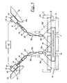
- FIGS. 1 and 2 the arrangement of the spray nozzle adjusting device according to the invention in the strand guide of a continuous slab caster is shown schematically.
- Fig. 2 12 illustrates, in a partial longitudinal section through the continuous casting plant, the transition region from a bent section of the strand guide into a straight section of the strand guide in the outlet region of a continuous casting plant, making obvious the essential components of the spray nozzle adjustment device and their advantages in these two geometrically different positions.
- each spray nozzles 4, 5, 6, 7, 8 are arranged, wherein in a plane normal to Strangtransportides, for example, in a sectional plane in the spray nozzle 5, two spray nozzles 5a, 5b are arranged, with which fan-shaped coolant jets 9a, 9b are applied to a broad side surface 1a of the metal strand 1 that a largely even coolant is applied. If, for example, a metal strand 1 'wider than the metal strand 1 is cast, the positions of the spray nozzles 5a, 5b are adjusted according to the positions represented by the reference numerals 5a' and 5b 'in dashed lines.
- fan-shaped coolant jets 9a 'and 9b' are automatically adjusted, with which in turn the entire strand width can be uniformly cooled.
- the required amount of coolant can be regulated, for example, by an increased injection pressure to the now larger strand width.
- Each spray nozzle 5a, 5b is connected to a spray nozzle holder 10, which in turn with the adjusting piston 11 of an adjusting 12, no relative movement permitting, is firmly connected.
- the adjusting device 12 is indicated only schematically with the actuating piston 11 by a double arrow illustrating the common possibility of movement of the actuating piston and the spray nozzle holder 10.
- the adjusting device 12 comprises a hydraulically or pneumatically actuable pressure cylinder 40.
- the spray nozzle holder 10 is, for example, in a format change from a metal strand 1 with a first widths to a metal strand 1 'with a second, for example, greater width by retracting the control piston 11 of the adjusting 12 in one Position corresponding to the spray nozzle holder 10 'brought, whereby the optimum for this casting width coolant jet is adjusted.
- the adjusting device 12 is attached to the frame construction of the strand guide 2 in a region which is as far as possible from the hot metal strand, thus on a support bracket 13 on the side remote from the hot metal strand 1 side of the strand guide frame construction.
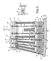
- a plurality of injection nozzles 4, 5, 6 or 7, 8 arranged one after another in this respective region in the strand conveying direction are fastened to a common injection nozzle holder 10, 10 'and can be adjusted together in the case of an adjusting movement exerted on the injection nozzle holder.
- the strand guide is composed of several strand guide segments, all in the strand conveying direction arranged one behind the other and attached to a extending over the longitudinal extent of the strand guide segment spray nozzle holder spray nozzles be positioned together with an adjustment of the spray nozzle holder.
- spray nozzle holder spray nozzles be positioned together with an adjustment of the spray nozzle holder.
- each spray nozzle 4, 5, 6 within the arcuate strand guide with a coolant passage 15 is pivotally mounted on the spray nozzle holder 10.
- the long coolant line 16, which extends transversely through the frame construction of the strand guide between the coolant passage 15 and the spray nozzle head 17, is guided in a guide element 18, which is fastened to the frame construction of the strand guide.
- the guide element 18 is designed as a guide fork 19 with a guide slot 19a which is open in a plane normal to the strand conveying direction.
- the coolant line 16 is slidably fixed in position and allows alignment of the spray nozzle head 17 and thus the coolant jet 9 to the middle between adjacent strand guide rollers 3a, 3b, ....
- the coolant passage 15 and the spray nozzle 4th , 5, ... at the spray nozzle holder 10 a bending of the spray nozzle is avoided in the region of the coolant line.
- the guide elements 18 are attached to the frame structure of the strand guide 2, not shown.
- support plates 20 are arranged in the region of cranked coolant lines, which reinforce the bending or vibration stability of the coolant lines in a plane normal to the strand conveying direction ( Fig. 1 ).
- the coolant line comprises a line for the actual coolant and a line for the atomizer. The mixture of the two components and the formation of the coolant jet 9 takes place in the spray nozzle head 17th
- the spray nozzle holder 10 comprises two profile tubes 22, 23 for the supply, passage and distribution of a coolant, such as treated cooling water, and a Zerstäubermediums, preferably air, to any number of spray nozzles 4.
- the profile tubes 22, 23 are provided with connecting tabs 24, 25th connected to the vibration-stable spray nozzle holder.
- the profile tubes are laterally associated mounting strips 26, 27, 29 in the region of openings 28, mounting surfaces 30 for the tight attachment of the coolant passage 15 of the spray nozzle.
- the passage openings 28, 29 correspond to media lines in the spray nozzle, which are indicated by the center lines.
- the passage openings 28, 29 in the mounting strips 26, 27 are optionally formed as slots 32, to give rise to no cross-sectional constriction even with a pivoting movement of the spray nozzle.
- the spray nozzle is fastened with a connecting screw 31 on the spray nozzle holder 10.
- a spring element and the through holes sealing elements can be assigned.
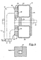
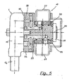
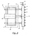
- FIG. 5 A second preferred embodiment for the structural design of the spray nozzle holder 10 and an attachment of the spray nozzle 4 on the spray nozzle holder is in FIG. 5 illustrated.
- the spray nozzle holder 10 in turn comprises two spaced apart firmly connected profile tubes 22, 23 for the supply of coolant and atomizer to the spray nozzles.
- slide bushings 33 are welded for the rotatable recording of rotary unions 34, through which the coolant and the atomizer through passages 28, 29 into the coolant passage 15 of the spray nozzle 4 is passed.
- the spray nozzle 4 is with its coolant passage 15 at the Mounted mounting surface 30 of the rotary feedthrough 34 and pivotally supported together with the rotary feedthrough and axially limited in the direction of the pivot axis 36 by a collar 37 in the slide bushes 33 of the spray nozzle holder 10.
- the passage openings 28, 29 are sealed by a plurality of sealing rings 38 in the transition region of the slide bushing for rotary feedthrough.
- the adjusting device 12 comprises a hydraulically or pneumatically actuated pressure medium cylinder 40 with an actuating piston 11 which is rigidly connected to the spray nozzle holder 10.
- the spray nozzle holder carries two guide elements 41 formed by guide rods, which are arranged on both sides of the actuating piston parallel to this, lying in a common plane with the actuating piston 11.
- the guide elements 41 pass through the base frame 42 of the adjusting and are slidable in this in the axial direction of the guide elements and perform upon actuation of the pressure medium cylinder 40 with a synchronous with the actuating piston 11 movement.
- the guide elements 41 are used to stabilize the spray nozzle holder 10.
- At the spray nozzle holder are each an elastic feed lines 43, 44 for coolant and atomizer for media supply of six spray nozzles 4, 5, 6, 7 ... connected. This ensures a substantial simplification of the coolant piping in the structurally restricted strand guide.
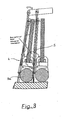
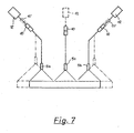
- Fig. 7 shows the arrangement of 3 spray nozzles 5a, 5b, 5c in a direction normal to the strand conveying direction plane between adjacent strand guide rollers. While the outer, the edge regions of a slab cooling spray nozzles 5a, 5b in the already with reference to Fig. 1 described type are arranged adaptable to different strand widths, the inner, the central region of the slab cooling spray nozzle 5c is unchangeable in position. It is arranged on a permanently mounted spray nozzle holder 10. However, it is also possible that the spray nozzle holder of this centrally located spray nozzle is connected to the actuating piston of an adjusting device 12 shown in dashed lines and all 3 spray nozzles are adapted with matched adjustment movements at different strand widths.
- Each adjusting device 12 are associated with control and regulating devices 45 which are connected to the system control system 46 and which comprise at least one displacement sensor and a preferably hydraulic actuator for positional determination of the spray nozzles ( Fig. 1 ).
- control and regulating devices 45 which are connected to the system control system 46 and which comprise at least one displacement sensor and a preferably hydraulic actuator for positional determination of the spray nozzles ( Fig. 1 ).
- basic settings of the continuous casting plant are made, which are given for example by the specification of a G cashformates and the steel quality and predetermine the position of the spray nozzles in the strand guide. These default values for the positioning of the spray nozzles are approached synchronously by the control and regulating devices.
Landscapes
- Engineering & Computer Science (AREA)
- Mechanical Engineering (AREA)
- Continuous Casting (AREA)
- Nozzles (AREA)
- Pressure-Spray And Ultrasonic-Wave- Spray Burners (AREA)
- Reciprocating Pumps (AREA)
Priority Applications (1)
| Application Number | Priority Date | Filing Date | Title |
|---|---|---|---|
| PL07711678T PL2010347T3 (pl) | 2006-04-25 | 2007-02-27 | Urządzenie nastawcze do dysz natryskowych |
Applications Claiming Priority (2)
| Application Number | Priority Date | Filing Date | Title |
|---|---|---|---|
| AT0069906A AT503526B1 (de) | 2006-04-25 | 2006-04-25 | Spritzdüsen-verstelleinrichtung |
| PCT/EP2007/001658 WO2007121804A1 (de) | 2006-04-25 | 2007-02-27 | Spritzdüsen-verstelleinrichtung |
Publications (2)
| Publication Number | Publication Date |
|---|---|
| EP2010347A1 EP2010347A1 (de) | 2009-01-07 |
| EP2010347B1 true EP2010347B1 (de) | 2010-04-07 |
Family
ID=38196582
Family Applications (1)
| Application Number | Title | Priority Date | Filing Date |
|---|---|---|---|
| EP07711678A Active EP2010347B1 (de) | 2006-04-25 | 2007-02-27 | Spritzdüsen-verstelleinrichtung |
Country Status (10)
| Country | Link |
|---|---|
| EP (1) | EP2010347B1 (ru) |
| KR (1) | KR20090010999A (ru) |
| CN (1) | CN101432086B (ru) |
| AT (2) | AT503526B1 (ru) |
| DE (1) | DE502007003406D1 (ru) |
| ES (1) | ES2343380T3 (ru) |
| PL (1) | PL2010347T3 (ru) |
| RU (1) | RU2431542C2 (ru) |
| UA (1) | UA95477C2 (ru) |
| WO (1) | WO2007121804A1 (ru) |
Cited By (3)
| Publication number | Priority date | Publication date | Assignee | Title |
|---|---|---|---|---|
| EP2412459A1 (de) | 2010-07-29 | 2012-02-01 | Siemens VAI Metals Technologies GmbH | Spritzdüsen-Verstelleinrichtung |
| EP2527061A1 (de) | 2011-05-27 | 2012-11-28 | Siemens VAI Metals Technologies GmbH | Verfahren zur Kühlung eines metallischen Strangs und Schaltventil zum intermittierenden Öffnen und Schließen eines Volumenstroms eines Kühlmediums |
| US8522858B2 (en) | 2006-01-11 | 2013-09-03 | Sms Siemag Aktiengesellschaft | Method and apparatus for continuous casting |
Families Citing this family (21)
| Publication number | Priority date | Publication date | Assignee | Title |
|---|---|---|---|---|
| AT506673B1 (de) | 2008-05-13 | 2012-07-15 | Siemens Vai Metals Tech Gmbh | Verfahren zur kühlmittelaufbringung auf einen gegossenen metallstrang in einer stranggiessanlage und stranggiessanlage dazu |
| DE102009010251A1 (de) * | 2008-10-01 | 2010-04-08 | Sms Siemag Aktiengesellschaft | Vorrichtung und Verfahren zur Sekundärkühlung in einer Stranggießanlage |
| DE102009005679A1 (de) | 2009-01-22 | 2010-07-29 | Sms Siemag Aktiengesellschaft | Stranggießanlage mit Spritzdüsenanordnung |
| CN101642804B (zh) * | 2009-09-09 | 2011-01-19 | 北京科技大学 | 一种实现连铸板坯均匀二次冷却的方法 |
| CN103347626B (zh) * | 2011-02-07 | 2015-07-22 | 西门子Vai金属科技有限责任公司 | 用于通过能够移动的冷却喷嘴的在连铸设备的连铸坯导引装置中的定位来对连铸坯的温度进行调节的方法 |
| KR101360552B1 (ko) * | 2011-12-19 | 2014-02-11 | 주식회사 포스코 | 연주 설비 |
| KR101460660B1 (ko) * | 2012-04-20 | 2014-11-13 | 주식회사 포스코 | 냉각장치 및 이를 구비하는 연속주조기용 세그먼트 |
| KR101373160B1 (ko) * | 2012-05-01 | 2014-03-11 | 주식회사 포스코 | 더미바 냉각유닛 및 상기 더미바 냉각유닛을 구비하는 더미바 카 |
| CN102717046A (zh) * | 2012-06-29 | 2012-10-10 | 秦皇岛首秦金属材料有限公司 | 一种厚板坯连铸机二冷水自动调宽的计算方法 |
| KR101504976B1 (ko) * | 2012-12-26 | 2015-03-23 | 주식회사 포스코 | 냉각장치 및 이를 구비하는 연속주조기용 세그먼트 |
| CN103398852A (zh) * | 2013-08-01 | 2013-11-20 | 中国北方发动机研究所(天津) | 一种活塞冷却油量测试装置和测试方法 |
| AT516075B1 (de) * | 2014-07-25 | 2018-09-15 | Primetals Technologies Austria GmbH | Kühlung eines metallischen Strangabschnitts |
| AT517772B1 (de) * | 2015-09-07 | 2018-12-15 | Primetals Technologies Austria GmbH | Sekundärkühlung eines Strangs in einer Stranggießanlage |
| CN105478705B (zh) * | 2016-01-20 | 2018-06-22 | 中冶赛迪工程技术股份有限公司 | 一种板坯二次冷却无级调节装置 |
| CN105458206B (zh) * | 2016-01-21 | 2017-10-17 | 中冶赛迪工程技术股份有限公司 | 一种板坯二次冷却方法 |
| DE102016107840A1 (de) * | 2016-04-27 | 2017-11-02 | Elwema Automotive Gmbh | Verfahren und Vorrichtung zum Reinigen von Werkstücken aus Metall |
| EP3318342A1 (de) * | 2016-11-07 | 2018-05-09 | Primetals Technologies Austria GmbH | Verfahren zum betreiben einer giesswalzverbundanlage |
| JP7227384B2 (ja) | 2018-09-25 | 2023-02-21 | プライメタルズ・テクノロジーズ・オーストリア・ゲーエムベーハー | 中間領域スプレーバーを固定するための保持デバイスを有するローラースタンド |
| KR102249954B1 (ko) * | 2019-10-02 | 2021-05-11 | 주식회사 포스코 | 연속주조용 냉각수 분사장치 및 이를 포함하는 연속주조설비 |
| CN111101996B (zh) * | 2019-12-30 | 2024-08-16 | 新疆工程学院 | 一种泡沫除尘装置 |
| CN111390144B (zh) * | 2020-05-23 | 2021-07-13 | 四会市星驰铸造有限公司 | 一种具有智能冷却功能的铸造系统及铸造方法 |
Family Cites Families (6)
| Publication number | Priority date | Publication date | Assignee | Title |
|---|---|---|---|---|
| AT323921B (de) * | 1973-07-27 | 1975-08-11 | Voest Ag | Kuhleinrichtung für kontinuierlich zu giessende stränge |
| CH572370A5 (ru) * | 1974-02-28 | 1976-02-13 | Concast Ag | |
| DE2636666C2 (de) * | 1976-08-14 | 1978-06-29 | Demag Ag, 4100 Duisburg | Spritzdüsen-Anordnung für Metall-, insbesondere für StahlstranggieBanlagen für extrem breite Stahlbrammen |
| DE2939322C2 (de) * | 1979-09-28 | 1986-09-11 | Mannesmann AG, 4000 Düsseldorf | Vorrichtung zur Änderung des Abstandes von Spritzbalken einer Stranggießanlage |
| JPS6122615A (ja) | 1984-07-09 | 1986-01-31 | 工業技術院長 | 乾式電解コンデンサ |
| US5212975A (en) * | 1991-05-13 | 1993-05-25 | International Rolling Mill Consultants, Inc. | Method and apparatus for cooling rolling mill rolls and flat rolled products |
-
2006
- 2006-04-25 AT AT0069906A patent/AT503526B1/de not_active IP Right Cessation
-
2007
- 2007-02-27 CN CN200780015171XA patent/CN101432086B/zh active Active
- 2007-02-27 DE DE502007003406T patent/DE502007003406D1/de active Active
- 2007-02-27 EP EP07711678A patent/EP2010347B1/de active Active
- 2007-02-27 ES ES07711678T patent/ES2343380T3/es active Active
- 2007-02-27 RU RU2008146398/02A patent/RU2431542C2/ru not_active IP Right Cessation
- 2007-02-27 WO PCT/EP2007/001658 patent/WO2007121804A1/de active Application Filing
- 2007-02-27 UA UAA200813193A patent/UA95477C2/ru unknown
- 2007-02-27 KR KR1020087028835A patent/KR20090010999A/ko active Search and Examination
- 2007-02-27 AT AT07711678T patent/ATE463311T1/de active
- 2007-02-27 PL PL07711678T patent/PL2010347T3/pl unknown
Cited By (9)
| Publication number | Priority date | Publication date | Assignee | Title |
|---|---|---|---|---|
| US8522858B2 (en) | 2006-01-11 | 2013-09-03 | Sms Siemag Aktiengesellschaft | Method and apparatus for continuous casting |
| US8596335B2 (en) | 2006-01-11 | 2013-12-03 | Sms Siemag Aktiengesellschaft | Method and apparatus for continuous casting |
| EP2412459A1 (de) | 2010-07-29 | 2012-02-01 | Siemens VAI Metals Technologies GmbH | Spritzdüsen-Verstelleinrichtung |
| WO2012013474A2 (de) | 2010-07-29 | 2012-02-02 | Siemens Vai Metals Technologies Gmbh | Spritzdüsen-verstelleinrichtung |
| WO2012013474A3 (de) * | 2010-07-29 | 2012-09-20 | Siemens Vai Metals Technologies Gmbh | Spritzdüsen-verstelleinrichtung |
| EP2598270B1 (de) | 2010-07-29 | 2015-09-02 | Primetals Technologies Austria GmbH | Spritzdüsen-verstelleinrichtung |
| EP2527061A1 (de) | 2011-05-27 | 2012-11-28 | Siemens VAI Metals Technologies GmbH | Verfahren zur Kühlung eines metallischen Strangs und Schaltventil zum intermittierenden Öffnen und Schließen eines Volumenstroms eines Kühlmediums |
| WO2012163878A1 (de) * | 2011-05-27 | 2012-12-06 | Siemens Vai Metals Technologies Gmbh | Verfahren zur kühlung eines metallischen strangs und schaltventil zum intermittierenden öffnen und schliessen eines volumenstroms eines kühlmediums |
| RU2605723C2 (ru) * | 2011-05-27 | 2016-12-27 | Прайметалз Текнолоджиз Аустрия Гмбх | Способ охлаждения металлической отливаемой заготовки и переключательный клапан для периодического открывания и перекрывания объемного потока охлаждающей среды |
Also Published As
| Publication number | Publication date |
|---|---|
| AT503526B1 (de) | 2008-07-15 |
| RU2431542C2 (ru) | 2011-10-20 |
| DE502007003406D1 (de) | 2010-05-20 |
| KR20090010999A (ko) | 2009-01-30 |
| ES2343380T3 (es) | 2010-07-29 |
| RU2008146398A (ru) | 2010-05-27 |
| UA95477C2 (ru) | 2011-08-10 |
| PL2010347T3 (pl) | 2010-09-30 |
| WO2007121804A1 (de) | 2007-11-01 |
| ATE463311T1 (de) | 2010-04-15 |
| AT503526A1 (de) | 2007-11-15 |
| EP2010347A1 (de) | 2009-01-07 |
| CN101432086A (zh) | 2009-05-13 |
| CN101432086B (zh) | 2011-09-07 |
Similar Documents
| Publication | Publication Date | Title |
|---|---|---|
| EP2010347B1 (de) | Spritzdüsen-verstelleinrichtung | |
| DE3027846C2 (de) | Verfahren und Einrichtung zum Abkühlen von Blech, insbesondere Stahlblech, mittels Wasser | |
| EP0701022B1 (de) | Auftragswerk zum direkten oder indirekten Auftragen eines flüssigen oder pastösen Mediums auf eine laufende Materialbahn | |
| DE2636666C2 (de) | Spritzdüsen-Anordnung für Metall-, insbesondere für StahlstranggieBanlagen für extrem breite Stahlbrammen | |
| EP2288458B1 (de) | Strangführungssegment | |
| WO2010057610A1 (de) | Vorrichtung zum kühlen einer walze in einem walzgerät | |
| DE4432177A1 (de) | Auftragswerk zum direkten oder indirekten Auftragen eines flüssigen oder pastösen Mediums auf eine laufende Materialbahn | |
| DE19649073C2 (de) | Vorrichtung zur Abkühlung von Strangpreßprofilen | |
| EP0997577B1 (de) | Stoffauflauf | |
| EP3150291B1 (de) | Verfahren und vorrichtung zum kühlen einer in einem walzgerüst angeordneten walze | |
| EP0028686B1 (de) | Vorrichtung zum Kühlen von insbesondere Block- und Knüppelsträngen | |
| DE29520678U1 (de) | Auftragwerk zum direkten oder indirekten Auftragen eines flüssigen oder pastösen Mediums auf eine laufende Materialbahn | |
| DE19726890B4 (de) | Sprühdüse und Sprühsystem zum Aufsprühen von Flüssigkeit auf eine Materialbahn | |
| EP0440884B1 (de) | Vorrichtung zum Wölben von Glasscheiben | |
| DE4106764C2 (de) | Kanalwand, insbesondere für einen Papiermaschinen-Stoffauflauf | |
| DE102012201157A1 (de) | Verfahren und Vorrichtung zur Relativpositionierung eines Düsenbalkens einer Walzgerüsteinlaufarmatur | |
| EP0083917B1 (de) | Stranggiessanlage | |
| EP0728241B1 (de) | Auftragswerk zum direkten oder indirekten auftragen eines flüssigen oder pastösen mediums auf eine laufende materialbahn | |
| EP1366838B1 (de) | Kühlanordnung für das Walzgerüst einer Stranggussanlage | |
| EP0010728A1 (de) | Stranggiessanlage mit oszillierender Durchlaufkokille | |
| DE102008041119A1 (de) | Vorrichtung zum direkten oder indirekten Auftragen eines flüssigen oder pastösen Auftragmediums auf eine bewegbare Materialbahn | |
| DE3039443A1 (de) | Sekundaerkuehlung einer stahlstraggiessanlage | |
| EP3453466B1 (de) | Walzstrasse zum walzen eines metallischen guts und verfahren zum betreiben einer walzstrasse | |
| DE102009005679A1 (de) | Stranggießanlage mit Spritzdüsenanordnung | |
| DE19946998B4 (de) | Vorrichtung zur Abkühlung eines metallischen Pressbolzens oder Stangenabschnitts |
Legal Events
| Date | Code | Title | Description |
|---|---|---|---|
| PUAI | Public reference made under article 153(3) epc to a published international application that has entered the european phase |
Free format text: ORIGINAL CODE: 0009012 |
|
| 17P | Request for examination filed |
Effective date: 20081002 |
|
| AK | Designated contracting states |
Kind code of ref document: A1 Designated state(s): AT BE BG CH CY CZ DE DK EE ES FI FR GB GR HU IE IS IT LI LT LU LV MC NL PL PT RO SE SI SK TR |
|
| AX | Request for extension of the european patent |
Extension state: AL BA HR MK RS |
|
| RIN1 | Information on inventor provided before grant (corrected) |
Inventor name: WAHL, HELMUT Inventor name: FELLINGER, KURT Inventor name: ZIEGLER, GUENTER Inventor name: HOECHTEL, FRANZ, JOSEF Inventor name: FUERHOFER, HORST Inventor name: GUTTENBRUNNER, JOSEF Inventor name: STARRERMAIR, THOMAS Inventor name: HAMMERL, JOACHIM Inventor name: KRIEGNER, OTHMAR Inventor name: POEPPL, JOHANN |
|
| 17Q | First examination report despatched |
Effective date: 20090330 |
|
| GRAP | Despatch of communication of intention to grant a patent |
Free format text: ORIGINAL CODE: EPIDOSNIGR1 |
|
| GRAS | Grant fee paid |
Free format text: ORIGINAL CODE: EPIDOSNIGR3 |
|
| GRAA | (expected) grant |
Free format text: ORIGINAL CODE: 0009210 |
|
| AK | Designated contracting states |
Kind code of ref document: B1 Designated state(s): AT BE BG CH CY CZ DE DK EE ES FI FR GB GR HU IE IS IT LI LT LU LV MC NL PL PT RO SE SI SK TR |
|
| REG | Reference to a national code |
Ref country code: GB Ref legal event code: FG4D Free format text: NOT ENGLISH |
|
| REG | Reference to a national code |
Ref country code: CH Ref legal event code: EP |
|
| REG | Reference to a national code |
Ref country code: IE Ref legal event code: FG4D Free format text: LANGUAGE OF EP DOCUMENT: GERMAN |
|
| REF | Corresponds to: |
Ref document number: 502007003406 Country of ref document: DE Date of ref document: 20100520 Kind code of ref document: P |
|
| REG | Reference to a national code |
Ref country code: NL Ref legal event code: T3 |
|
| REG | Reference to a national code |
Ref country code: ES Ref legal event code: FG2A Ref document number: 2343380 Country of ref document: ES Kind code of ref document: T3 |
|
| PG25 | Lapsed in a contracting state [announced via postgrant information from national office to epo] |
Ref country code: SI Free format text: LAPSE BECAUSE OF FAILURE TO SUBMIT A TRANSLATION OF THE DESCRIPTION OR TO PAY THE FEE WITHIN THE PRESCRIBED TIME-LIMIT Effective date: 20100407 |
|
| LTIE | Lt: invalidation of european patent or patent extension |
Effective date: 20100407 |
|
| REG | Reference to a national code |
Ref country code: PL Ref legal event code: T3 |
|
| REG | Reference to a national code |
Ref country code: IE Ref legal event code: FD4D |
|
| PG25 | Lapsed in a contracting state [announced via postgrant information from national office to epo] |
Ref country code: SE Free format text: LAPSE BECAUSE OF FAILURE TO SUBMIT A TRANSLATION OF THE DESCRIPTION OR TO PAY THE FEE WITHIN THE PRESCRIBED TIME-LIMIT Effective date: 20100407 Ref country code: LT Free format text: LAPSE BECAUSE OF FAILURE TO SUBMIT A TRANSLATION OF THE DESCRIPTION OR TO PAY THE FEE WITHIN THE PRESCRIBED TIME-LIMIT Effective date: 20100407 |
|
| PG25 | Lapsed in a contracting state [announced via postgrant information from national office to epo] |
Ref country code: IS Free format text: LAPSE BECAUSE OF FAILURE TO SUBMIT A TRANSLATION OF THE DESCRIPTION OR TO PAY THE FEE WITHIN THE PRESCRIBED TIME-LIMIT Effective date: 20100807 Ref country code: FI Free format text: LAPSE BECAUSE OF FAILURE TO SUBMIT A TRANSLATION OF THE DESCRIPTION OR TO PAY THE FEE WITHIN THE PRESCRIBED TIME-LIMIT Effective date: 20100407 Ref country code: LV Free format text: LAPSE BECAUSE OF FAILURE TO SUBMIT A TRANSLATION OF THE DESCRIPTION OR TO PAY THE FEE WITHIN THE PRESCRIBED TIME-LIMIT Effective date: 20100407 |
|
| PG25 | Lapsed in a contracting state [announced via postgrant information from national office to epo] |
Ref country code: CY Free format text: LAPSE BECAUSE OF FAILURE TO SUBMIT A TRANSLATION OF THE DESCRIPTION OR TO PAY THE FEE WITHIN THE PRESCRIBED TIME-LIMIT Effective date: 20100609 |
|
| PLBI | Opposition filed |
Free format text: ORIGINAL CODE: 0009260 |
|
| PG25 | Lapsed in a contracting state [announced via postgrant information from national office to epo] |
Ref country code: EE Free format text: LAPSE BECAUSE OF FAILURE TO SUBMIT A TRANSLATION OF THE DESCRIPTION OR TO PAY THE FEE WITHIN THE PRESCRIBED TIME-LIMIT Effective date: 20100407 Ref country code: IE Free format text: LAPSE BECAUSE OF FAILURE TO SUBMIT A TRANSLATION OF THE DESCRIPTION OR TO PAY THE FEE WITHIN THE PRESCRIBED TIME-LIMIT Effective date: 20100407 Ref country code: DK Free format text: LAPSE BECAUSE OF FAILURE TO SUBMIT A TRANSLATION OF THE DESCRIPTION OR TO PAY THE FEE WITHIN THE PRESCRIBED TIME-LIMIT Effective date: 20100407 Ref country code: PT Free format text: LAPSE BECAUSE OF FAILURE TO SUBMIT A TRANSLATION OF THE DESCRIPTION OR TO PAY THE FEE WITHIN THE PRESCRIBED TIME-LIMIT Effective date: 20100809 |
|
| 26 | Opposition filed |
Opponent name: SMS SIEMAG AG Effective date: 20110107 |
|
| PLAX | Notice of opposition and request to file observation + time limit sent |
Free format text: ORIGINAL CODE: EPIDOSNOBS2 |
|
| PG25 | Lapsed in a contracting state [announced via postgrant information from national office to epo] |
Ref country code: RO Free format text: LAPSE BECAUSE OF FAILURE TO SUBMIT A TRANSLATION OF THE DESCRIPTION OR TO PAY THE FEE WITHIN THE PRESCRIBED TIME-LIMIT Effective date: 20100407 Ref country code: SK Free format text: LAPSE BECAUSE OF FAILURE TO SUBMIT A TRANSLATION OF THE DESCRIPTION OR TO PAY THE FEE WITHIN THE PRESCRIBED TIME-LIMIT Effective date: 20100407 Ref country code: CZ Free format text: LAPSE BECAUSE OF FAILURE TO SUBMIT A TRANSLATION OF THE DESCRIPTION OR TO PAY THE FEE WITHIN THE PRESCRIBED TIME-LIMIT Effective date: 20100407 |
|
| RAP2 | Party data changed (patent owner data changed or rights of a patent transferred) |
Owner name: SIEMENS VAI METALS TECHNOLOGIES GMBH |
|
| PG25 | Lapsed in a contracting state [announced via postgrant information from national office to epo] |
Ref country code: GR Free format text: LAPSE BECAUSE OF FAILURE TO SUBMIT A TRANSLATION OF THE DESCRIPTION OR TO PAY THE FEE WITHIN THE PRESCRIBED TIME-LIMIT Effective date: 20100708 |
|
| PLBB | Reply of patent proprietor to notice(s) of opposition received |
Free format text: ORIGINAL CODE: EPIDOSNOBS3 |
|
| PG25 | Lapsed in a contracting state [announced via postgrant information from national office to epo] |
Ref country code: MC Free format text: LAPSE BECAUSE OF NON-PAYMENT OF DUE FEES Effective date: 20110228 |
|
| REG | Reference to a national code |
Ref country code: CH Ref legal event code: PL |
|
| PG25 | Lapsed in a contracting state [announced via postgrant information from national office to epo] |
Ref country code: CH Free format text: LAPSE BECAUSE OF NON-PAYMENT OF DUE FEES Effective date: 20110228 Ref country code: LI Free format text: LAPSE BECAUSE OF NON-PAYMENT OF DUE FEES Effective date: 20110228 |
|
| REG | Reference to a national code |
Ref country code: AT Ref legal event code: MM01 Ref document number: 463311 Country of ref document: AT Kind code of ref document: T Effective date: 20120227 |
|
| PG25 | Lapsed in a contracting state [announced via postgrant information from national office to epo] |
Ref country code: LU Free format text: LAPSE BECAUSE OF NON-PAYMENT OF DUE FEES Effective date: 20110227 |
|
| PG25 | Lapsed in a contracting state [announced via postgrant information from national office to epo] |
Ref country code: AT Free format text: LAPSE BECAUSE OF NON-PAYMENT OF DUE FEES Effective date: 20120227 |
|
| PG25 | Lapsed in a contracting state [announced via postgrant information from national office to epo] |
Ref country code: TR Free format text: LAPSE BECAUSE OF FAILURE TO SUBMIT A TRANSLATION OF THE DESCRIPTION OR TO PAY THE FEE WITHIN THE PRESCRIBED TIME-LIMIT Effective date: 20100407 Ref country code: BG Free format text: LAPSE BECAUSE OF FAILURE TO SUBMIT A TRANSLATION OF THE DESCRIPTION OR TO PAY THE FEE WITHIN THE PRESCRIBED TIME-LIMIT Effective date: 20100707 |
|
| PLCK | Communication despatched that opposition was rejected |
Free format text: ORIGINAL CODE: EPIDOSNREJ1 |
|
| PG25 | Lapsed in a contracting state [announced via postgrant information from national office to epo] |
Ref country code: HU Free format text: LAPSE BECAUSE OF FAILURE TO SUBMIT A TRANSLATION OF THE DESCRIPTION OR TO PAY THE FEE WITHIN THE PRESCRIBED TIME-LIMIT Effective date: 20100407 |
|
| APBM | Appeal reference recorded |
Free format text: ORIGINAL CODE: EPIDOSNREFNO |
|
| APBP | Date of receipt of notice of appeal recorded |
Free format text: ORIGINAL CODE: EPIDOSNNOA2O |
|
| APAH | Appeal reference modified |
Free format text: ORIGINAL CODE: EPIDOSCREFNO |
|
| APBQ | Date of receipt of statement of grounds of appeal recorded |
Free format text: ORIGINAL CODE: EPIDOSNNOA3O |
|
| PGFP | Annual fee paid to national office [announced via postgrant information from national office to epo] |
Ref country code: PL Payment date: 20150126 Year of fee payment: 9 |
|
| RAP2 | Party data changed (patent owner data changed or rights of a patent transferred) |
Owner name: PRIMETALS TECHNOLOGIES AUSTRIA GMBH |
|
| REG | Reference to a national code |
Ref country code: FR Ref legal event code: PLFP Year of fee payment: 10 |
|
| REG | Reference to a national code |
Ref country code: FR Ref legal event code: TP Owner name: PRIMETALS TECHNOLOGIES AUSTRIA GMBH, AT Effective date: 20160413 |
|
| REG | Reference to a national code |
Ref country code: DE Ref legal event code: R082 Ref document number: 502007003406 Country of ref document: DE Representative=s name: KINNSTAETTER, KLAUS, DIPL.-PHYS.UNIV., DE |
|
| PLAB | Opposition data, opponent's data or that of the opponent's representative modified |
Free format text: ORIGINAL CODE: 0009299OPPO |
|
| REG | Reference to a national code |
Ref country code: DE Ref legal event code: R082 Ref document number: 502007003406 Country of ref document: DE Representative=s name: KINNSTAETTER, KLAUS, DIPL.-PHYS.UNIV., DE Ref country code: DE Ref legal event code: R081 Ref document number: 502007003406 Country of ref document: DE Owner name: PRIMETALS TECHNOLOGIES AUSTRIA GMBH, AT Free format text: FORMER OWNER: SIEMENS VAI METALS TECHNOLOGIES GMBH & CO. KG, LINZ, AT |
|
| REG | Reference to a national code |
Ref country code: GB Ref legal event code: 732E Free format text: REGISTERED BETWEEN 20161013 AND 20161019 |
|
| R26 | Opposition filed (corrected) |
Opponent name: SMS GROUP GMBH Effective date: 20110107 |
|
| REG | Reference to a national code |
Ref country code: FR Ref legal event code: PLFP Year of fee payment: 11 |
|
| REG | Reference to a national code |
Ref country code: DE Ref legal event code: R100 Ref document number: 502007003406 Country of ref document: DE |
|
| APBU | Appeal procedure closed |
Free format text: ORIGINAL CODE: EPIDOSNNOA9O |
|
| PLBN | Opposition rejected |
Free format text: ORIGINAL CODE: 0009273 |
|
| STAA | Information on the status of an ep patent application or granted ep patent |
Free format text: STATUS: OPPOSITION REJECTED |
|
| 27O | Opposition rejected |
Effective date: 20170425 |
|
| PG25 | Lapsed in a contracting state [announced via postgrant information from national office to epo] |
Ref country code: PL Free format text: LAPSE BECAUSE OF NON-PAYMENT OF DUE FEES Effective date: 20160227 |
|
| REG | Reference to a national code |
Ref country code: FR Ref legal event code: PLFP Year of fee payment: 12 |
|
| PGFP | Annual fee paid to national office [announced via postgrant information from national office to epo] |
Ref country code: NL Payment date: 20180216 Year of fee payment: 12 |
|
| PGFP | Annual fee paid to national office [announced via postgrant information from national office to epo] |
Ref country code: GB Payment date: 20180216 Year of fee payment: 12 Ref country code: ES Payment date: 20180327 Year of fee payment: 12 |
|
| PGFP | Annual fee paid to national office [announced via postgrant information from national office to epo] |
Ref country code: BE Payment date: 20180216 Year of fee payment: 12 Ref country code: FR Payment date: 20180223 Year of fee payment: 12 |
|
| REG | Reference to a national code |
Ref country code: NL Ref legal event code: MM Effective date: 20190301 |
|
| GBPC | Gb: european patent ceased through non-payment of renewal fee |
Effective date: 20190227 |
|
| REG | Reference to a national code |
Ref country code: BE Ref legal event code: MM Effective date: 20190228 |
|
| PG25 | Lapsed in a contracting state [announced via postgrant information from national office to epo] |
Ref country code: NL Free format text: LAPSE BECAUSE OF NON-PAYMENT OF DUE FEES Effective date: 20190301 Ref country code: GB Free format text: LAPSE BECAUSE OF NON-PAYMENT OF DUE FEES Effective date: 20190227 |
|
| PG25 | Lapsed in a contracting state [announced via postgrant information from national office to epo] |
Ref country code: FR Free format text: LAPSE BECAUSE OF NON-PAYMENT OF DUE FEES Effective date: 20190228 Ref country code: BE Free format text: LAPSE BECAUSE OF NON-PAYMENT OF DUE FEES Effective date: 20190228 |
|
| REG | Reference to a national code |
Ref country code: ES Ref legal event code: FD2A Effective date: 20200331 |
|
| PG25 | Lapsed in a contracting state [announced via postgrant information from national office to epo] |
Ref country code: ES Free format text: LAPSE BECAUSE OF NON-PAYMENT OF DUE FEES Effective date: 20190228 |
|
| PGFP | Annual fee paid to national office [announced via postgrant information from national office to epo] |
Ref country code: DE Payment date: 20240219 Year of fee payment: 18 |
|
| PGFP | Annual fee paid to national office [announced via postgrant information from national office to epo] |
Ref country code: IT Payment date: 20240228 Year of fee payment: 18 |