EP0701022B1 - Auftragswerk zum direkten oder indirekten Auftragen eines flüssigen oder pastösen Mediums auf eine laufende Materialbahn - Google Patents
Auftragswerk zum direkten oder indirekten Auftragen eines flüssigen oder pastösen Mediums auf eine laufende Materialbahn Download PDFInfo
- Publication number
- EP0701022B1 EP0701022B1 EP95113027A EP95113027A EP0701022B1 EP 0701022 B1 EP0701022 B1 EP 0701022B1 EP 95113027 A EP95113027 A EP 95113027A EP 95113027 A EP95113027 A EP 95113027A EP 0701022 B1 EP0701022 B1 EP 0701022B1
- Authority
- EP
- European Patent Office
- Prior art keywords
- applicator unit
- lip
- side lip
- unit according
- adjusting
- Prior art date
- Legal status (The legal status is an assumption and is not a legal conclusion. Google has not performed a legal analysis and makes no representation as to the accuracy of the status listed.)
- Expired - Lifetime
Links
Images


Classifications
-
- D—TEXTILES; PAPER
- D21—PAPER-MAKING; PRODUCTION OF CELLULOSE
- D21H—PULP COMPOSITIONS; PREPARATION THEREOF NOT COVERED BY SUBCLASSES D21C OR D21D; IMPREGNATING OR COATING OF PAPER; TREATMENT OF FINISHED PAPER NOT COVERED BY CLASS B31 OR SUBCLASS D21G; PAPER NOT OTHERWISE PROVIDED FOR
- D21H23/00—Processes or apparatus for adding material to the pulp or to the paper
- D21H23/02—Processes or apparatus for adding material to the pulp or to the paper characterised by the manner in which substances are added
- D21H23/22—Addition to the formed paper
- D21H23/32—Addition to the formed paper by contacting paper with an excess of material, e.g. from a reservoir or in a manner necessitating removal of applied excess material from the paper
-
- B—PERFORMING OPERATIONS; TRANSPORTING
- B05—SPRAYING OR ATOMISING IN GENERAL; APPLYING FLUENT MATERIALS TO SURFACES, IN GENERAL
- B05C—APPARATUS FOR APPLYING FLUENT MATERIALS TO SURFACES, IN GENERAL
- B05C1/00—Apparatus in which liquid or other fluent material is applied to the surface of the work by contact with a member carrying the liquid or other fluent material, e.g. a porous member loaded with a liquid to be applied as a coating
- B05C1/04—Apparatus in which liquid or other fluent material is applied to the surface of the work by contact with a member carrying the liquid or other fluent material, e.g. a porous member loaded with a liquid to be applied as a coating for applying liquid or other fluent material to work of indefinite length
- B05C1/08—Apparatus in which liquid or other fluent material is applied to the surface of the work by contact with a member carrying the liquid or other fluent material, e.g. a porous member loaded with a liquid to be applied as a coating for applying liquid or other fluent material to work of indefinite length using a roller or other rotating member which contacts the work along a generating line
- B05C1/0817—Apparatus in which liquid or other fluent material is applied to the surface of the work by contact with a member carrying the liquid or other fluent material, e.g. a porous member loaded with a liquid to be applied as a coating for applying liquid or other fluent material to work of indefinite length using a roller or other rotating member which contacts the work along a generating line characterised by means for removing partially liquid or other fluent material from the roller, e.g. scrapers
-
- B—PERFORMING OPERATIONS; TRANSPORTING
- B05—SPRAYING OR ATOMISING IN GENERAL; APPLYING FLUENT MATERIALS TO SURFACES, IN GENERAL
- B05C—APPARATUS FOR APPLYING FLUENT MATERIALS TO SURFACES, IN GENERAL
- B05C5/00—Apparatus in which liquid or other fluent material is projected, poured or allowed to flow on to the surface of the work
- B05C5/02—Apparatus in which liquid or other fluent material is projected, poured or allowed to flow on to the surface of the work the liquid or other fluent material being discharged through an outlet orifice by pressure, e.g. from an outlet device in contact or almost in contact, with the work
- B05C5/0283—Flat jet coaters, i.e. apparatus in which the liquid or other fluent material is projected from the outlet as a cohesive flat jet in direction of the work
-
- D—TEXTILES; PAPER
- D21—PAPER-MAKING; PRODUCTION OF CELLULOSE
- D21H—PULP COMPOSITIONS; PREPARATION THEREOF NOT COVERED BY SUBCLASSES D21C OR D21D; IMPREGNATING OR COATING OF PAPER; TREATMENT OF FINISHED PAPER NOT COVERED BY CLASS B31 OR SUBCLASS D21G; PAPER NOT OTHERWISE PROVIDED FOR
- D21H23/00—Processes or apparatus for adding material to the pulp or to the paper
- D21H23/02—Processes or apparatus for adding material to the pulp or to the paper characterised by the manner in which substances are added
- D21H23/22—Addition to the formed paper
- D21H23/52—Addition to the formed paper by contacting paper with a device carrying the material
- D21H23/56—Rolls
-
- B—PERFORMING OPERATIONS; TRANSPORTING
- B05—SPRAYING OR ATOMISING IN GENERAL; APPLYING FLUENT MATERIALS TO SURFACES, IN GENERAL
- B05C—APPARATUS FOR APPLYING FLUENT MATERIALS TO SURFACES, IN GENERAL
- B05C5/00—Apparatus in which liquid or other fluent material is projected, poured or allowed to flow on to the surface of the work
- B05C5/02—Apparatus in which liquid or other fluent material is projected, poured or allowed to flow on to the surface of the work the liquid or other fluent material being discharged through an outlet orifice by pressure, e.g. from an outlet device in contact or almost in contact, with the work
- B05C5/0254—Coating heads with slot-shaped outlet
- B05C5/0262—Coating heads with slot-shaped outlet adjustable in width, i.e. having lips movable relative to each other in order to modify the slot width, e.g. to close it
Definitions
- the invention relates to a commissioned work for direct or indirect application of a liquid or pasty medium a running material web, in particular made of paper or Carton.
- the liquid or pasty Medium via a color distribution tube that is located within a the length of the order extending bar arranged is fed.
- the medium passes through the paint distribution tube Through openings in an equalization room and flows from there via a feed gap to the metering gap, from which the liquid or pasty medium then in the form of a free Beam emerges.
- the material web can, for example, on the surface of a roller.
- the free jet is first applied to the Surface of an applicator roller applied to in from there a nip through which the material web runs, transferred from the application roller to the material web become.
- That lip of the two forming the metering gap Lips which is on the side of the metering gap on which the indirect application of the medium the application roller or at direct application of the medium to the material web Commissioned work is referred to as the inlet lip. Accordingly, the second lip on the side of the Dosing gap is on which the applicator roller or Material web runs away from the commissioned work as the outlet side Inscribed lip.
- the lip between the drain Order and the fine metering device a collecting trough arranged to remove excess liquid or pasty medium, that from the commissioning plant or from the fine metering device expires to collect. Because of these conditions and the Operation of liquid or pasty materials running on the application unit Medium can with such conventional commissioned works Column setting not made during operation become.
- extrusion applicator is known from US-A-4984533, which has an extruder head seen in cross section essentially two opposite plate-like Parts that have a circular between them, in a lower area of the extruder head Distribution room for the extruded application medium and one adjoining, extending upwards Define extruder slot.
- extruder slot In the exit area of the Extruder slot are the two plate-like parts on theirs Outside beveled, so that there is a kind of lip forms.
- the material web to be coated runs on this Extrusion application directly over the lips of the Extruder head away, and the extruder head is during the Extrusion pressed against the material web, so that the application medium exiting the extruder head flat on the Material web is extruded.
- the drain-side lip of the Extruder head also takes on the function of a Doctor element, which wipes the extruded medium.
- a Doctor element By an attacking lip on the outlet side Adjustment mechanism is the lip on the outlet side lip on the inlet side or pivotable away from it.
- One formed by the circular distribution space Thin point serves as a pivot axis.
- the invention is based on the technical problem a commissioned work of the type described at the beginning Gap setting of the metering gap even while the meter is running To be able to make operations.
- an adjustment device provided with the lip on the inlet side at a distance to the lip on the outlet side is adjustable.
- this Distance seen along the length of the application, in zones differently adjustable, for example local Compensate for manufacturing inaccuracies or a cross profile of the applied liquid or pasty medium realize that differently in some areas is, e.g. flattened at the edges of the material web.
- a preset of the whole is over the length of the metering gap possible.
- the Gap setting even during operation be made because of the accessibility of the Adjustment device not by a drain side Fine metering device or one located on the outlet side Gutter is affected.
- an operation of Adjustment device not through liquid or draining pasty medium hampers, since this is located in the outlet side Area of the commissioned work is collected.
- the to and lips on the outlet side to limit the metering gap Have surface sections that are either straight or curved run. So it can be the surface sections of both lips each be straight or curved. About that In addition, one of the two lips can extend beyond its free end the other lip also extends to be extended this extended section a curved deflecting surface for to form the liquid or pasty medium to be applied. In particular, it is preferred that the inlet lip on its free end has a concave deflection surface for the has liquid or pasty medium. In principle, one such deflection surface, however, also be convexly curved, or that Free end of one lip can be considered a straight one Guide surface section over the free end of the second lip be led out.
- the inlet side Lip shaped like a comb.
- the lip on the inlet side has a web running along its length on, of which processes are distributed over the length or Extend protrusions.
- lip on the inlet side by the adjustment device in zones rotationally around a parallel to the longitudinal axis of the lip moving axis movable.
- the Lip in sections around this parallel to its longitudinal axis Swivel the axis in this way by swiveling the Lip to drain lip to reduce the metering gap or by swiveling away from the drain lip To increase the metering gap.
- the lip on the inlet side by the adjustment device in zones translationally in a transverse to the level of the metering gap moving direction. That means that lip on the inlet side in sections to the lip on the outlet side can be moved towards or away from this to the Reduce or enlarge the metering gap accordingly.
- the Adjustment device a mechanical adjustment mechanism on.
- a mechanical adjustment mechanism can diverse ways, for example using Set screws, levers and the like.
- a preferred embodiment of the mechanical Adjustment mechanism is a number of over the The length of the applicator is distributed adjusting screws to be provided, each directly or indirectly on the bar support the application unit and in thread engagement with the lip on the inlet side, with the adjusting screws Spring elements are biased.
- By rotating the Adjusting the lip on the inlet side of the outlet lip are pulled away or swung away or be pushed or pivoted towards this.
- By Operation of individual adjustment screws can be local Gap adjustment can be made while at even Actuation of all adjusting screws a total setting of Dosing gap made over the length of the application can be.
- By preloading the adjustment screws always ensures that a stable and play-free Column setting is present.
- Another advantageous embodiment of the mechanical Adjustment mechanism is a lever arm assembly to be provided over actuators over the length of the Order work are distributed, bending forces in the inlet side Lip initiates to by means of the resulting Bending deformations adjust the metering gap zone by zone.
- Actuation of individual actuators for the local application of Bending forces on the inlet lip using the Lever arm arrangement made a zone-wise gap adjustment be, and can also when actuating all actuators Total gap setting over the length of the application work be performed.
- adjustment device consist of a thermal, hydraulic, pneumatic, magnetic, magnetostrictive or to provide piezoelectric adjustment mechanism.
- Such Adjustment mechanisms can be constructive in their Design can be realized in many ways, whereby also combinations of the adjustment mechanism operating principles with each other or combinations of these adjustment mechanism operating principles with mechanical adjustment mechanisms can be executed.
- Zone-wise actuation of the servomotor adjustment device intended. This makes the adjustment process easier because the Actuators, e.g. Adjusting screws or the like, not have to be operated more by hand.
- the Adjustment device can be operated remotely.
- This Embodiment of the invention is precisely with regard to a Gap setting advantageous during ongoing operation, since the control of the adjustment device then on the one hand can be done centrally and on the other one control-related linkage of the adjustment device with other components of the coating system is made possible.
- Control of the adjustment device in an automatic Include control loop, which is based on measured values of the Cross profile of the applied liquid or pasty medium adjusts the adjustment device.
- this embodiment is therefore the column setting during the operation of the Automated coating system, making the fastest possible Adaptation of the commissioned work to changed conditions or There are irregularities during operation and so the Quality of the final product is improved.
- a second adjustment device for the drain side Lip provided with which the drain lip on the Length of the work in zones at a distance from it inlet lip is adjustable.
- This second Adjustment device can, as far as the spatial Allow circumstances, in one of the previous in Connection with the adjustment device for the inlet side Lippe explained embodiments can be executed.
- the adjustment device for the inlet side Lip for fine adjustment of the metering gap and the additional adjustment device for the drain-side lip for a rough adjustment of the metering gap.
- the total gap width can then be preset via the Adjustment device for the drain lip in conventionally when the coating system is at a standstill done while the sectional fine adjustment is also during operation by adjusting the adjustment device for the lip on the inlet side can be made.
- Actuator a nut on a threaded part of the Adjustment spindle is arranged and with which the inlet side Lip in its distance to the lip on the outlet side and thus the Width of the metering gap is adjustable.
- the adjusting spindle is preferably a spring element assigned. It is advantageous that the spring element supports a stationary component and the adjusting spindle in Direction of "closing” or “opening” the metering gap acted upon.
- each Adjustment spindle on a bending point It is advantageous the bending point in the form of a leaf spring-like thin spot educated.
- the broad side of the leaf spring-like Thin point along the horizontal axis of the adjustment spindle runs, the thin point about a parallel to the longitudinal axis the axis of the application is elastically deformable.
- the spring element is preferably provided with a preload nut preloadable.
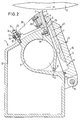
- a bar 10 which extends over the entire Length of the commissioned work extends.
- a compensation room 8 on which continues in a feed channel 7.
- the feed channel 7 opens into a metering gap 4 which is between a lip 2 on the inlet side and a lip 3 on the outlet side is formed.
- a concavely curved deflection surface 5 educated.
- the liquid or pasty medium is indicated by arrows 6 indicated.
- the application unit 1 is opposite an application roller 13 for an indirect order of the medium to be applied.
- the Direction of rotation of the application roller 13 is by an arrow clarifies.
- the lip 2 on the inlet side on the side of the metering gap 4 who arrives the application roller 13, that is, while the drain-side lip 3 on the opposite side of the Dosing gap is on the application roller 13 from Dosing gap runs away, i.e. runs out.
- the liquid or pasty Medium 6 is first supplied via the paint distribution pipe 9, then passes into the compensation chamber 8 and flows through the Feed channel 7 to the metering gap 4, from which the medium is then in a free jet (not shown) emerges, whereby by the concavely curved deflection surface 5 of the lip 2 on the inlet side a deflection of the application jet in the direction of the tangent the application roller 13 takes place.
- the liquid or pasty medium 6 is in the form of this free jet on the surface of the Application roller 13 applied and then after passing one downstream fine metering device (not shown), where the applied medium for setting a predetermined cross profile is scraped off, a nip fed through which a web of paper or cardboard, possibly also made of a textile material that runs there the liquid or pasty medium from the application roller 13 decreases.
- the embodiment is both with a Adjustment device for the inlet lip 2 as well an adjustment device for the drain-side lip 3 fitted.
- the adjustment device for the drain-side lip 3 is in formed in a manner known per se, the outlet side Lip 3 has a thin point 14.
- the thin section 14 corresponds to an articulated connection and allows one Swiveling the above the thin point in the drawing located section of the drain-side lip 3 within of a certain pivoting range, the pivoting around one running through the thin point 14 and to the longitudinal axis of the beam 10 parallel axis.
- a front wall 11, with the drain-side lip 3 on her in the drawing section below the thin section is firmly connected is rigidly fixed in operation, but it is required can be folded down about a joint 15, e.g. for cleaning purposes.
- the Back of the front wall 11 is as a drain surface 16 for excess liquid or pasty medium is formed.
- the area located above the thin point 14 are distributed over the length of the commissioned work Set screws 17 arranged with their head on the Support the rear of the front wall 11 and engage in thread with the pivotable section of the drain-side lip 3 stand. Furthermore, the length of the Stopper screws 18 distributed over the application unit provided which is in threaded engagement with the front wall 11 stand and with their bolt end on the swiveling section support lip 3 on the outlet side. Finally there is a cover 19 on the back of the front wall 11 arranged, which protects the adjusting device and as Drainage surface for excess medium 6 is used.
- the adjustment device for the lip 2 on the inlet side explained.
- On the bar 10 is a two-piece flange 20 fixedly arranged with Through bores 21 for receiving adjusting screws 22 is provided.
- the adjustment screws 22 are on the Longitudinal extension of the bar 10 is distributed.
- With a Collar 23 the adjusting screws are supported on the flange element 20 as it engages with its free bolt end with lip 2 on the inlet side.
- With a compression spring 24 around the free bolt area of each adjusting screw 22 is arranged around, the flange member 20 and the lip 2 on the inlet side stretched apart.
- the inlet side Lip 2 is provided with a thin point 25 so that the in section above the thin section this lip is pivotable about a certain area.
- the inlet side lip 2 is on her in the drawing section located below the thin point 25 by means of Fastening screws 26 attached to the beam 10.
- the adjustment device for the drain-side lip 3 is for the rough setting of the gap width of the metering gap 4 provided while the adjustment device for the lip 2 on the inlet side of a fine adjustment of the gap width of the Dosing gap 4 is used.
- the adjusting screws 22 are included a fine thread that allows precise fine adjustment allowed. Due to the biasing action of the compression springs 24, the alternatively e.g. can also be designed as disc springs, is always a stable and play-free adjustment of the lip 2 on the inlet side guaranteed.
- the lip 3 on the outlet side no adjustment device for Adjustment of this lip is provided, and the lip 3 is over connecting screws 27 shown only schematically firmly connected to the front wall 11. Therefore, the lip 3 on the outlet side also no thin spot as in the first Embodiment on.
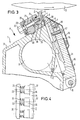
- lever arms 28 are arranged, which by means of fastening screws 29 firmly with the inlet side Lip 2 are connected.
- the lip 2 on the inlet side opposite ends of the lever arms 28 are with joint heads 30 fitted.
- the rod ends 30 are each rigid on one on the beam 10 attached bolts 31 pushed held there between two nuts 32 each.
- the Screw nuts 32 each point on the joint head 30 facing end face a spherical cap-shaped surface on.
- each Ball head 30 has a larger inner diameter than that Outer diameter of the rigid bolt 31, the joint head 30 with respect to the bolt 31 in a certain range be pivoted without bending forces on the bolt transfer.
- the two nuts 32 on each bolt 31 are additionally secured by a lock nut 34.
- Adjustment device for the drain lip Coarse adjustment of the metering gap and an adjustment device for the inlet lip for fine adjustment of the Dosing gap now takes over Adjustment device for the inlet lip 2 the entire Column setting function.
- the adjustment device for the inlet lip according to the first embodiment only smaller adjustment paths, otherwise the adjusting screws 22 at the entry into the threaded holes of the inlet lip 2 would experience an improper bend.
- the fine adjustment of the metering gap are feasible adjustment paths completely sufficient. Because in the second Embodiment realized much larger adjustment paths is an articulated connection between the rigid lever arms 28 and the rigid pin 31 trained so that when pivoting the lip 2 on the inlet side Lever arm 28 no undue bends in the bolt cause.
- the column setting is carried out analogously to Adjustment device for the inlet lip at the first Embodiment.
- To swivel the in the Drawing upper section of the lip 2 on the inlet side cause one or more lever arms 28 by means of Screw nuts 32 along the longitudinal axis of the bolt 31 transferred.
- the rigid lever arms 28 then transmit the Displacement along the bolt 31 in a pivoting of the inlet lip 2.
- the lip 2 on the inlet side is comb-shaped, i.e. it consists of a web 35, which extends over the length of the application unit 1 extends, and over the length of the web distributed processes 36.
- the individual processes 36 are each displaceable in the direction of their longitudinal axis 37 guided in a flange element 20 which is fixed to the beam 10 connected is.
- the flange element 20 is with Through holes 21 provided through each Adjusting screws 22 are guided.
- the flange element 20 is fixed from two interconnected sub-elements formed a bundle 23 each adjusting screw 22 enclose so that this Supports the collar against the flange element.
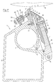
- the applicator 1 a support device, which is executed here in the form of a bar 10.
- the bar 10 extends over the entire length of the commissioned work.
- a distribution pipe 9 for the to be applied liquid or pasty medium formed which is usually is referred to as a color distribution pipe.
- This follows connected via passage openings 12, an equalizing space 8 that continues in a feed channel.
- the feed channel 7 opens into a metering gap 4 which is between a lip 2 on the inlet side and a lip 3 on the outlet side is formed.
- a concavely curved deflection surface 5 educated.
- the liquid or pasty medium is indicated by arrows 6 indicated.
- the applicator 1 is a roller 13 (i.e. one Application roller for an indirect application of the to be applied Medium or support roller wrapped around the material web direct order).
- the direction of rotation of the roller 13 is indicated by an arrow.
- the inlet lip 2 is on the side of the metering gap 4, on which a point on the surface of the Roller 13 arrives at the metering gap, that is to say runs in.
- the lip 3 on the outlet side lies on the opposite one Side of the metering gap on which the said point on the Surface of the roller 13 runs away from the metering gap, that is expires.
- the liquid or pasty Medium 6 is first supplied via the paint distribution pipe 9, then passes into the compensation chamber 8 and flows through the Feed channel 7 to the metering gap 4, from which the medium is then in a free jet, not shown, emerges. This is done through the concavely curved deflecting surface 5 of the inlet side Lip 2 deflects the application jet towards one tangent to the roller 13.
- the liquid or pasty Medium 6 is in the form of this free jet on the surface the roller 13 or applied directly to the material web. It is usually followed by a not shown downstream fine metering device to a correct one Streaked weight.
- the applicator 1 is both with an adjustment device for the inlet lip 2 as well as with a Adjustment device for the drain lip 3 fitted.
- the adjustment device for the outlet side Lip 3 has already been linked to previous ones Exemplary embodiments explained, so that in this regard to the is referred to there.
- the adjustment device for the lip 2 on the inlet side explained.
- On the bar 10 is a Length of the beam 10 extending component 20 stationary arranged, which with through holes 28 for receiving is provided by adjusting spindles 22.
- the adjusting spindles 22 are about the longitudinal extent of the bar 10 and Component 20 arranged distributed, as shown in Figure 6 is.
- the anti-rotation device can, for example with one not shown separately in the drawing Lock nut or otherwise, e.g. by gluing.
- the latter can be provided with a bending point 21 which is advantageously made in the form of a leaf spring-like thin point.
- This bending point 21 lies in one plane with the axis of the adjusting spindle 22.
- the width of the bending or thin point should correspond approximately to the diameter of the adjusting spindle, as can be seen in FIG. 6 of the top view of the application mechanism, or can even be made somewhat wider his. Since this thin point is therefore wide and, due to its leaf spring-like small thickness, has only a low bending stiffness, it can thus be elastically deformed about an axis 27 running parallel to the longitudinal axis of the application unit 1.
- the adjusting spindle 22 without Bend be made. That makes sense where the lip 2 on the inlet side represents a less rigid strip and there for the profiling of the gap 4 less forces are transferred.
- the adjusting spindle 22 also takes only a schematic illustrated spring element 24, which is preferably made of Disc springs exist.
- the spring element 24 can be tensioned against the component 20, whereby a freely selectable preload of the spring element is adjustable independently of the gap adjustment.
- the adjusting spindle 22 is relative to the supporting beam 10 by means of an adjusting device 26 adjustable in the axial direction.
- Actuator can be on the other end of the Adjustment spindle 22 screwed nut 26 are used.
- the nut 26 acts from the opposite side (i.e. opposite to lip 2) on component 20.
- the component 20 can e.g. as seen in Fig. 5, as one on the Beam 10 fixed angle to be executed. But it can also one welded onto the beam 10, for example Be ledge, as can be seen from FIG. 7.
- the adjusting spindle 22 is in the direction "Close” of the metering gap 4 is applied. At The presence of the elastic thin spot 21 is experienced again a slight bending deformation, but in the opposite direction or in their starting position.
- the inlet lip 2 can be adjusted, it is with a thin point 30, which can also be a joint, Mistake.
- the one in the drawing above the thin section located section of this lip is around a certain one The area can thus be swiveled.
- fastening screws 31 the lip 2 is attached to the beam 10.
- the adjustment for the drain-side lip 3 is for the Elimination of manufacturing-related tolerances of the gap width the metering gap 4 provided, whereas the Adjustment device for the inlet lip 2 of the Profiling the gap width of the metering gap 4 is used.
- the adjusting spindles 22 are therefore with a fine thread provided, which allows a precise fine adjustment.
Landscapes
- Coating Apparatus (AREA)
- Absorbent Articles And Supports Therefor (AREA)
- Cleaning Implements For Floors, Carpets, Furniture, Walls, And The Like (AREA)
- Nozzles (AREA)
- Photographic Developing Apparatuses (AREA)
- Non-Silver Salt Photosensitive Materials And Non-Silver Salt Photography (AREA)
- Formation And Processing Of Food Products (AREA)
Description
- Fig. 1
- eine schematisierte Querschnittsdarstellung eines ersten Ausführungsbeispiels des erfindungsgemäßen Auftragswerks;
- Fig. 2
- eine schematisierte Querschnittsdarstellung eines zweiten Ausführungsbeispiels des erfindungsgemäßen Auftragswerks;
- Fig. 3
- eine schematisierte Querschnittsdarstellung eines dritten Ausführungsbeispiels des erfindungsgemäßen Auftragswerks;
- Fig. 4
- einen Ausschnitt einer teilweise geschnittenen Draufsicht in Richtung des Pfeils A auf die zulaufseitige Lippe und die zugehörige Verstelleinrichtung in Fig. 3;
- Fig. 5
- eine schematisierte Querschnittsdarstellung eines vierten Ausführungsbeispieles des erfindungsgemäßen Auftragswerkes;
- Fig. 6
- einen Ausschnitt auf die Draufsicht des in Fig. 5 dargestellten vierten Ausführungsbeispieles des erfindungsgemäßen Auftragswerkes;
- Fig. 7
- eine schematisierte Querschnittsdarstellung eines fünften Ausführungsbeispieles des erfindungsgemäßen Auftragswerkes.
Diese Biegestelle 21 liegt in einer Ebene mit der Achse der Verstellspindel 22. Die Breite der Biege- bzw. Dünnstelle sollte annähernd dem Durchmesser der Verstellspindel entsprechen, wie in Fig. 6 der Draufsicht auf das Auftragswerk erkennbar ist, oder kann sogar noch etwas breiter ausgeführt sein. Da diese Dünnstelle also breit ist und aufgrund ihrer blattfederartigen geringen Dicke nur eine geringe Biegesteifigkeit besitzt, ist sie somit um eine parallel zur Längsachse des Auftragswerkes 1 laufenden Achse 27 elastisch verformbar. Das bietet zum einen den Vorteil, daß mit der Biegestelle 21 eine Art Gelenk geschaffen wird, das (bei der Verstellung der Lippe 2) eine im wesentlichen widerstandslose Änderung des Winkels zwischen Lippe 2 und der Achse der (im ortsfesten Bauteil gelagerten) Verstellspindel 22 zuläßt. Zum anderen besteht in der blattfederartigen Dünnstelle eine große Querschnittsfläche, die geeignet ist, höhere Kräfte als bisher bei der Spalteinstellung auf die zulaufseitige Lippe 2 zu übertragen. Das ist insbesondere dann von Vorteil, wenn die zulaufseitige Lippe 2 aus einem relativ steifen Material besteht.
Claims (22)
- Auftragswerk zum direkten oder indirekten Auftragen eines flüssigen oder pastösen Mediums (6) auf eine laufende Materialbahn, insbesondere aus Papier oder Karton, miteinem als Freistrahldüse ausgebildeten Dosierspalt (4), der zwischen einer zulaufseitigen (2) und einer ablaufseitigen Lippe (3) gebildet ist, undeiner Verstelleinrichtung (20-25; 28-34), mit der die zulaufseitige Lippe (2) über die Länge des Auftragswerks (1) zonenweise in ihrem Abstand zur ablaufseitigen Lippe (3) einstellbar ist.
- Auftragswerk nach Anspruch 1, dadurch gekennzeichnet, daß die zulaufseitige Lippe (2) an ihrem freien Ende eine konkav gekrümmte Umlenkfläche (5) für das flüssige oder pastöse Medium (6) aufweist.
- Auftragswerk nach Anspruch 1 oder 2, dadurch gekennzeichnet, daß die zulaufseitige Lippe (2) kammförmig (35, 36) ausgebildet ist.
- Auftragswerk nach einem der Ansprüche 1 bis 3, dadurch gekennzeichnet, daß die zulaufseitige Lippe (2) durch die Verstelleinrichtung zonenweise rotatorisch um eine parallel zur Längsachse des Auftragswerks (1) verlaufende Achse (25) beweglich ist.
- Auftragswerk nach einem der Ansprüche 1 bis 3, dadurch gekennzeichnet, daß die zulaufseitige Lippe (2) durch die Verstelleinrichtung zonenweise translatorisch in einer quer zur Ebene des Dosierspalts (4) verlaufenden Richtung (37) beweglich ist.
- Auftragswerk nach einem der Ansprüche 1 bis 5, dadurch gekennzeichnet, daß die Verstelleinrichtung (20-25; 28-34) einen mechanischen Verstellmechanismus aufweist.
- Auftragswerk nach Anspruch 6, dadurch gekennzeichnet, daß der mechanische Verstellmechanismus eine Anzahl von über die Länge des Auftragswerks (1) verteilt angeordneten Justierschrauben (22) aufweist, die sich jeweils direkt oder indirekt an einem Balken (10) des Auftragswerks abstützen und in Gewindeeingriff mit der zulaufseitigen Lippe (2) stehen, wobei die Justierschrauben (22) durch Federelemente (24) vorgespannt sind.
- Auftragswerk nach Anspruch 6, dadurch gekennzeichnet, daß der mechanische Verstellmechanismus eine Hebelarmanordnung (28-30) aufweist, die über Stellglieder (31-34), die über die Länge des Auftragswerks (1) verteilt sind, Biegekräfte in die zulaufseitige Lippe (2) einleitet, um mittels der resultierenden Biegeverformungen den Dosierspalt (4) zonenweise einzustellen.
- Auftragswerk nach einem der Ansprüche 1 bis 5, dadurch gekennzeichnet, daß die Verstelleinrichtung einen thermischen, hydraulischen, pneumatischen, magnetischen, magnetostriktiven oder piezoelektrischen Verstellmechanismus aufweist.
- Auftragswerk nach einem der Ansprüche 1 bis 9, dadurch gekennzeichnet, daß Stellmotoren zur zonenweisen Betätigung der Verstelleinrichtung vorgesehen sind.
- Auftragswerk nach einem der Ansprüche 1 bis 10, dadurch gekennzeichnet, daß die Verstelleinrichtung ferngesteuert betätigbar ist.
- Auftragswerk nach Anspruch 11, dadurch gekennzeichnet, daß die ferngesteuerte zonenweise Ansteuerung der Verstelleinrichtung in einem Regelkreis automatisch aufgrund von Meßwerten des Querprofils des aufgetragenen flüssigen oder pastösen Mediums (6) vorgenommen wird.
- Auftragswerk nach einem der Ansprüche 1 bis 12, dadurch gekennzeichnet, daß zusätzlich zur Verstelleinrichtung für die zulaufseitige Lippe (2) eine zweite Verstelleinrichtung (14, 17, 18) für die ablaufseitige Lippe (3) vorgesehen ist, mit der die ablaufseitige Lippe (3) über die Länge des Auftragswerks (1) zonenweise in ihrem Abstand zur zulaufseitigen Lippe (2) einstellbar ist.
- Auftragswerk nach Anspruch 13, dadurch gekennzeichnet, daß die Verstelleinrichtung (20-25; 28-34) für die zulaufseitige Lippe (2) für eine Feineinstellung des Dosierspalts (4) und die zusätzliche Verstelleinrichtung (14, 17, 18) für die ablaufseitige Lippe (3) für eine Grobeinstellung des Dosierspalts (4) ausgebildet ist.
- Auftragswerk nach Anspruch 1, dadurch gekennzeichnet, daßdie zulaufseitige Lippe (2) mit einer Anzahl von über die Länge des Auftragswerkes (1) verteilt angeordneten Verstellspindeln (22) verbunden ist, mit denen die zulaufseitige Lippe (2) über die Länge des Auftragswerkes (1) zonenweise in ihrem Abstand zur ablaufseitigen Lippe (3) einstellbar ist, wobeijede Verstellspindel (22) starr und verdrehsicher mit der zulaufseitigen Lippe (2) verbunden ist undjede Verstellspindel (22) relativ zu einer Trageinrichtung (10) des Auftragswerkes (1) mittels einer Stelleinrichtung (26) in Achsrichtung verstellbar ist.
- Auftragswerk nach Anspruch 15, dadurch gekennzeichnet, daß die Stelleinrichtung (26) eine Mutter ist, die auf einem Gewindeteil der Verstellspindel angeordnet ist und mit der die zulaufseitige Lippe (2) in ihrem Abstand zur ablaufseitigen Lippe (3) und damit die Weite des Dosierspaltes (4) einstellbar ist.
- Auftragswerk nach Anspruch 15, dadurch gekennzeichnet, daß der Verstellspindel (22) ein Federelement (24) zugeordnet ist.
- Auftragswerk nach Anspruch 17, dadurch gekennzeichnet, daß sich das Federelement (24) an einem ortsfesten Bauteil (20) abstützt und die Verstellspindel (22) in Richtung "schließen" oder "Öffnen" des Dosierspaltes (4) beaufschlagt.
- Auftragswerk nach einem der Ansprüche 15 bis 18, dadurch gekennzeichnet, daß jede Verstellspindel (22) eine Biegestelle (21) aufweist.
- Auftragswerk nach Anspruch 19, dadurch gekennzeichnet, daß die Biegestelle (21) in Form einer blattfederartigen Dünnstelle ausgebildet ist.
- Auftragswerk nach Anspruch 18, dadurch gekennzeichnet, daß die Breitseite der blattfederartigen Dünnstelle entlang der horizontalen Achse der Verstellspindel (22) verläuft, wobei die Dünnstelle um eine parallel zur Längsachse des Auftragswerkes (1) verlaufende Achse (27) elastisch verformbar ist.
- Auftragswerk nach Anspruch 17, dadurch gekennzeichnet, daß das Federelement (24) mit einer Vorspannmutter (23) vorspannbar ist.
Applications Claiming Priority (4)
| Application Number | Priority Date | Filing Date | Title |
|---|---|---|---|
| DE4432177 | 1994-09-09 | ||
| DE4432177A DE4432177A1 (de) | 1994-09-09 | 1994-09-09 | Auftragswerk zum direkten oder indirekten Auftragen eines flüssigen oder pastösen Mediums auf eine laufende Materialbahn |
| DE19514772 | 1995-04-21 | ||
| DE19514772A DE19514772A1 (de) | 1994-09-09 | 1995-04-21 | Auftragswerk zum direkten oder indirekten Auftragen eines flüssigen oder pastösen Mediums auf eine laufende Materialbahn |
Publications (3)
| Publication Number | Publication Date |
|---|---|
| EP0701022A2 EP0701022A2 (de) | 1996-03-13 |
| EP0701022A3 EP0701022A3 (de) | 1997-05-14 |
| EP0701022B1 true EP0701022B1 (de) | 2001-04-04 |
Family
ID=25939992
Family Applications (1)
| Application Number | Title | Priority Date | Filing Date |
|---|---|---|---|
| EP95113027A Expired - Lifetime EP0701022B1 (de) | 1994-09-09 | 1995-08-18 | Auftragswerk zum direkten oder indirekten Auftragen eines flüssigen oder pastösen Mediums auf eine laufende Materialbahn |
Country Status (7)
| Country | Link |
|---|---|
| US (1) | US5785253A (de) |
| EP (1) | EP0701022B1 (de) |
| JP (1) | JPH08173880A (de) |
| AT (1) | ATE200325T1 (de) |
| BR (1) | BR9504624A (de) |
| CA (1) | CA2157832C (de) |
| FI (1) | FI109769B (de) |
Cited By (1)
| Publication number | Priority date | Publication date | Assignee | Title |
|---|---|---|---|---|
| DE10359116A1 (de) * | 2003-12-17 | 2005-07-14 | Voith Paper Patent Gmbh | Auftragsvorrichtung |
Families Citing this family (26)
| Publication number | Priority date | Publication date | Assignee | Title |
|---|---|---|---|---|
| US6319552B1 (en) | 1992-09-11 | 2001-11-20 | Stora Enso North America Corp. | Method of decreasing skip coating on a paper web |
| DE29520678U1 (de) * | 1995-12-29 | 1996-05-30 | Voith Sulzer Papiermaschinen GmbH, 89522 Heidenheim | Auftragwerk zum direkten oder indirekten Auftragen eines flüssigen oder pastösen Mediums auf eine laufende Materialbahn |
| DE29610773U1 (de) * | 1996-06-19 | 1996-09-05 | Voith Sulzer Papiermaschinen GmbH, 89522 Heidenheim | Freistrahldüsen-Auftragseinrichtung |
| EP0821102B1 (de) * | 1996-07-08 | 2002-03-27 | Voith Paper Patent GmbH | Auftragwerk zum direkten Auftragen eines flüssigen oder pastösen Mediums auf eine laufende Materialbahn, insbesondere aus Papier oder Karton |
| DE19637164A1 (de) * | 1996-09-12 | 1998-03-19 | Voith Sulzer Papiermasch Gmbh | Verfahren und Vorrichtung zum direkten oder indirekten Auftragen eines flüssigen oder pastösen Mediums auf eine laufende Materialbahn |
| FI109215B (fi) * | 1996-10-28 | 2002-06-14 | Metso Paper Inc | Menetelmä ja sovitelma liikkuvan paperi- tai kartonkiradan päällystämiseksi |
| DE19651739A1 (de) * | 1996-12-12 | 1998-06-18 | Voith Sulzer Papiermasch Gmbh | Auftragwerk zum direkten oder indirekten Auftragen eines flüssigen oder pastösen Streichmediums auf eine laufende Materialbahn, insbesondere aus Papier oder Karton |
| DE19651738A1 (de) * | 1996-12-12 | 1998-06-18 | Voith Sulzer Papiermasch Gmbh | Auftragswerk zum direkten oder indirekten Auftragen eines flüssigen oder pastösen Mediums auf eine laufende Oberfläche |
| DE19719128A1 (de) * | 1997-05-07 | 1998-11-12 | Jagenberg Papiertech Gmbh | Vorrichtung zum Auftragen von Beschichtungsmaterial |
| DE19734262A1 (de) * | 1997-08-07 | 1999-02-11 | Voith Sulzer Papiermasch Gmbh | Verfahren zum direkten oder indirekten Auftragen eines flüssigen oder pastösen Mediums auf eine laufende Materialbahn, insbesondere aus Papier oder Karton |
| DE19801140A1 (de) * | 1998-01-14 | 1999-07-15 | Voith Sulzer Papiertech Patent | Vorrichtung zum direkten oder indirekten Auftrag eines flüssigen bis pastösen Auftragsmediums auf eine laufende Materialbahn sowie Betriebsverfahren für eine solche Vorrichtung |
| DE19814491A1 (de) * | 1998-04-01 | 1999-10-07 | Voith Sulzer Papiertech Patent | Verfahren und Vorrichtung zur Vermeidung oder Beseitigung von Verstopfungen im Dosierspalt eines Düsenauftragswerks |
| DE19814490A1 (de) * | 1998-04-01 | 1999-10-07 | Voith Sulzer Papiertech Patent | Verfahren zur Vermeidung oder Beseitigung von Verstopfungen der Austrittsöffnung des Dosierspaltes eines Düsenauftragwerkes |
| DE19822505A1 (de) | 1998-05-19 | 1999-11-25 | Voith Sulzer Papiertech Patent | Beschichtungsverfahren |
| DE20122834U1 (de) | 2001-04-12 | 2008-03-27 | Voith Patent Gmbh | Auftragsvorrichtung |
| KR100648411B1 (ko) * | 2003-10-17 | 2006-11-24 | 주식회사 디엠에스 | 유체분사노즐 |
| DE10358220A1 (de) * | 2003-12-12 | 2005-07-07 | Voith Paper Patent Gmbh | Vorrichtung zum ein- oder beidseitigen Auftragen von flüssigem bis pastösem Auftragsmedium, insbesondere wässrige Pigmentsuspension, auf eine laufende Oberfläche |
| JP5498826B2 (ja) * | 2010-03-18 | 2014-05-21 | 株式会社城北精工所 | コーティングダイ |
| CN103170429B (zh) * | 2013-04-03 | 2015-11-11 | 广东顺德确丽机械有限公司 | 一种涂布机 |
| CN105344502A (zh) * | 2014-08-20 | 2016-02-24 | 宝山钢铁股份有限公司 | 高压滑块式狭缝喷射装置及其间隙调整方法 |
| DE102016014270A1 (de) | 2016-11-30 | 2018-05-30 | Dürr Systems Ag | Düsenvorrichtung zur Ausgabe von zwei sich annähernden Strahlen eines Abgabemediums |
| DE102016014269A1 (de) * | 2016-11-30 | 2018-05-30 | Dürr Systems Ag | Düsenvorrichtung mit zumindest zwei Düsenplatten und zumindest drei Öffnungen |
| KR102044849B1 (ko) * | 2018-02-01 | 2019-11-14 | 육경식 | 조립식 클리닝 노즐과 이것이 구비된 조립식 클리닝 장치 |
| DE102019113896A1 (de) * | 2019-05-24 | 2020-11-26 | Atlas Copco Ias Gmbh | Auftragsdüse |
| JP7160376B2 (ja) * | 2020-10-29 | 2022-10-25 | 有限会社タクショー | クリーナヘッド |
| CN119838809B (zh) * | 2024-12-27 | 2025-10-31 | 楚天科技股份有限公司 | 一种涂布装置的涂布刮刀高度调节方法、系统和介质 |
Family Cites Families (18)
| Publication number | Priority date | Publication date | Assignee | Title |
|---|---|---|---|---|
| CA491209A (en) * | 1953-03-10 | John Waldron Corporation | Method and apparatus for coating webs | |
| US2940418A (en) * | 1959-03-27 | 1960-06-14 | Black Clawson Co | Paper machinery |
| US3841557A (en) * | 1972-10-06 | 1974-10-15 | Nat Steel Corp | Coating thickness control and fluid handling |
| US4106429A (en) * | 1977-05-23 | 1978-08-15 | Beloit Corporation | Air knife with adjustable lip |
| US4250211A (en) * | 1978-05-31 | 1981-02-10 | Consolidated Papers, Inc. | Paper coating method and apparatus |
| US4251566A (en) * | 1978-10-12 | 1981-02-17 | Champion International Corporation | Gum thickness regulator |
| CA1134188A (en) * | 1980-04-03 | 1982-10-26 | Dominion Engineering Works Limited | Stock supply system for paper machine |
| DE3167426D1 (en) * | 1980-06-10 | 1985-01-10 | Erich Pagendarm | Fantail nozzle for producing a continuous gas or liquid veil, e.g. for burners |
| US4452833A (en) * | 1982-02-08 | 1984-06-05 | Consolidated Papers, Inc. | Paper coating method |
| US4749125A (en) * | 1987-01-16 | 1988-06-07 | Terronics Development Corp. | Nozzle method and apparatus |
| DE3731961A1 (de) * | 1987-09-23 | 1989-04-06 | Hoechst Ag | Vorrichtung zur spalteinstellung einer duese |
| JPH07106332B2 (ja) * | 1988-08-23 | 1995-11-15 | 富士写真フイルム株式会社 | 塗布装置 |
| DE3834719C2 (de) * | 1988-10-12 | 1997-07-10 | Hoechst Ag | Vorrichtung zur Spaltverstellung einer Düsenanordnung |
| US5067432A (en) * | 1990-05-23 | 1991-11-26 | Extrusion Dies, Inc. | Replaceable wiping insert for slot die head |
| FI105533B (fi) * | 1992-10-26 | 2000-09-15 | Valmet Paper Machinery Inc | Suihkupäällystyslaitteisto ja -menetelmä |
| CA2101358C (en) * | 1992-09-11 | 2000-10-24 | Wayne A. Damrau | Fountain applicator for coating a paper web and method |
| DE4327701C2 (de) * | 1993-08-19 | 1997-09-18 | Hofmann Walter Maschf | Verfahren zum Auftragen eines hochviskosen Markierungsstoffes in mehreren parallel nebeneinander liegenden Schichten auf eine ortsfeste Oberfläche und Auftragsvorrichtung zur Durchführung des Verfahrens |
| DE4341341C1 (de) * | 1993-12-06 | 1995-03-09 | Jagenberg Ag | Dosiersystem für Vorrichtungen zum Beschichten von Materialbahnen, insbesondere Papier- oder Kartonbahnen |
-
1995
- 1995-08-18 AT AT95113027T patent/ATE200325T1/de active
- 1995-08-18 EP EP95113027A patent/EP0701022B1/de not_active Expired - Lifetime
- 1995-09-06 US US08/524,030 patent/US5785253A/en not_active Expired - Lifetime
- 1995-09-06 BR BR9504624A patent/BR9504624A/pt not_active IP Right Cessation
- 1995-09-08 FI FI954216A patent/FI109769B/fi not_active IP Right Cessation
- 1995-09-08 CA CA002157832A patent/CA2157832C/en not_active Expired - Fee Related
- 1995-09-11 JP JP7258094A patent/JPH08173880A/ja active Pending
Cited By (1)
| Publication number | Priority date | Publication date | Assignee | Title |
|---|---|---|---|---|
| DE10359116A1 (de) * | 2003-12-17 | 2005-07-14 | Voith Paper Patent Gmbh | Auftragsvorrichtung |
Also Published As
| Publication number | Publication date |
|---|---|
| FI954216L (fi) | 1996-03-10 |
| FI109769B (fi) | 2002-10-15 |
| JPH08173880A (ja) | 1996-07-09 |
| ATE200325T1 (de) | 2001-04-15 |
| EP0701022A2 (de) | 1996-03-13 |
| CA2157832C (en) | 2007-05-22 |
| FI954216A0 (fi) | 1995-09-08 |
| CA2157832A1 (en) | 1996-03-10 |
| EP0701022A3 (de) | 1997-05-14 |
| BR9504624A (pt) | 1996-10-08 |
| US5785253A (en) | 1998-07-28 |
Similar Documents
| Publication | Publication Date | Title |
|---|---|---|
| EP0701022B1 (de) | Auftragswerk zum direkten oder indirekten Auftragen eines flüssigen oder pastösen Mediums auf eine laufende Materialbahn | |
| DE4432177A1 (de) | Auftragswerk zum direkten oder indirekten Auftragen eines flüssigen oder pastösen Mediums auf eine laufende Materialbahn | |
| EP2010347B1 (de) | Spritzdüsen-verstelleinrichtung | |
| EP0761877A2 (de) | Auftragswerk zum direkten oder indirekten Auftragen eines flüssigen oder pastösen Mediums auf eine laufende Materialbahn | |
| EP0418476B1 (de) | Vorrichtung zum Beschichten einer um eine Gegenwalze geführten Materialbahn | |
| DE19651739A1 (de) | Auftragwerk zum direkten oder indirekten Auftragen eines flüssigen oder pastösen Streichmediums auf eine laufende Materialbahn, insbesondere aus Papier oder Karton | |
| DE69110466T2 (de) | Streicheinrichtung mit flexiblem blatt und verfahren zur zusammengesetzten beanspruchung des blattes. | |
| DE29520678U1 (de) | Auftragwerk zum direkten oder indirekten Auftragen eines flüssigen oder pastösen Mediums auf eine laufende Materialbahn | |
| EP2310188A2 (de) | Vorrichtung zum schweissen und schneiden von ein- oder mehrlagigen materialien unter anwendung von ultraschallenergie | |
| EP0807710A1 (de) | Verfahren und Vorrichtung zum direkten oder indirekten Auftragen eines flüssigen oder pastösen Mediums auf eine laufende Materialbahn, insbesondere aus Papier oder Karton | |
| EP0583437B1 (de) | Abstützleiste für eine beschichtungsvorrichtung | |
| EP0781885A1 (de) | Auftragswerk zum direkten oder indirekten Auftragen eines flüssigen oder pastösen Mediums auf eine laufende Materialbahn | |
| EP0406529B1 (de) | Streicheinrichtung | |
| EP0896090B1 (de) | Verfahren zum direkten oder indirekten Auftragen eines flüssigen oder pastösen Mediums auf eine laufende Materialbahn, insbesondere aus Papier oder Karton | |
| DE19602483C1 (de) | Rollrakelbaugruppe | |
| EP0137837A1 (de) | Abstreifvorrichtung. | |
| DE10154809A1 (de) | Farbdosiersystem in einer Druckmaschine | |
| DE4230241C2 (de) | Auftragswerk zur Beschichtung von Bahnen aus Papier oder Karton | |
| EP0677613A2 (de) | Vorrichtung zum Auftragen von mindestens einem flüssigen Medium auf eine laufende Materialbahn | |
| DE19731947A1 (de) | Verfahren zum Steuern bzw. Regeln einer Vorrichtung zum Auftragen eines flüssigen oder pastösen Mediums auf eine Gegenfläche | |
| DE19549085A1 (de) | Auftragwerk zum direkten oder indirekten Auftragen eines flüssigen oder pastösen Mediums auf eine laufende Materialbahn | |
| EP1186703B1 (de) | Schaberanordnung | |
| EP0728241B1 (de) | Auftragswerk zum direkten oder indirekten auftragen eines flüssigen oder pastösen mediums auf eine laufende materialbahn | |
| DE4418464C2 (de) | Klingenhalterung | |
| DE29506731U1 (de) | Auftragswerk zur Beschichtung einer laufenden Warenbahn, insbesondere aus Papier oder Karton |
Legal Events
| Date | Code | Title | Description |
|---|---|---|---|
| PUAI | Public reference made under article 153(3) epc to a published international application that has entered the european phase |
Free format text: ORIGINAL CODE: 0009012 |
|
| AK | Designated contracting states |
Kind code of ref document: A2 Designated state(s): AT DE ES FR GB IT SE |
|
| PUAL | Search report despatched |
Free format text: ORIGINAL CODE: 0009013 |
|
| AK | Designated contracting states |
Kind code of ref document: A3 Designated state(s): AT DE ES FR GB IT SE |
|
| 17P | Request for examination filed |
Effective date: 19970617 |
|
| 17Q | First examination report despatched |
Effective date: 19980703 |
|
| RAP1 | Party data changed (applicant data changed or rights of an application transferred) |
Owner name: VOITH SULZER PAPIERTECHNIK PATENT GMBH |
|
| GRAG | Despatch of communication of intention to grant |
Free format text: ORIGINAL CODE: EPIDOS AGRA |
|
| GRAG | Despatch of communication of intention to grant |
Free format text: ORIGINAL CODE: EPIDOS AGRA |
|
| GRAH | Despatch of communication of intention to grant a patent |
Free format text: ORIGINAL CODE: EPIDOS IGRA |
|
| GRAH | Despatch of communication of intention to grant a patent |
Free format text: ORIGINAL CODE: EPIDOS IGRA |
|
| RAP1 | Party data changed (applicant data changed or rights of an application transferred) |
Owner name: VOITH PAPER PATENT GMBH |
|
| GRAA | (expected) grant |
Free format text: ORIGINAL CODE: 0009210 |
|
| AK | Designated contracting states |
Kind code of ref document: B1 Designated state(s): AT DE ES FR GB IT SE |
|
| PG25 | Lapsed in a contracting state [announced via postgrant information from national office to epo] |
Ref country code: IT Free format text: LAPSE BECAUSE OF FAILURE TO SUBMIT A TRANSLATION OF THE DESCRIPTION OR TO PAY THE FEE WITHIN THE PRESCRIBED TIME-LIMIT;WARNING: LAPSES OF ITALIAN PATENTS WITH EFFECTIVE DATE BEFORE 2007 MAY HAVE OCCURRED AT ANY TIME BEFORE 2007. THE CORRECT EFFECTIVE DATE MAY BE DIFFERENT FROM THE ONE RECORDED. Effective date: 20010404 Ref country code: GB Free format text: LAPSE BECAUSE OF FAILURE TO SUBMIT A TRANSLATION OF THE DESCRIPTION OR TO PAY THE FEE WITHIN THE PRESCRIBED TIME-LIMIT Effective date: 20010404 |
|
| REF | Corresponds to: |
Ref document number: 200325 Country of ref document: AT Date of ref document: 20010415 Kind code of ref document: T |
|
| REF | Corresponds to: |
Ref document number: 59509152 Country of ref document: DE Date of ref document: 20010510 |
|
| ET | Fr: translation filed | ||
| GBV | Gb: ep patent (uk) treated as always having been void in accordance with gb section 77(7)/1977 [no translation filed] |
Effective date: 20010404 |
|
| PG25 | Lapsed in a contracting state [announced via postgrant information from national office to epo] |
Ref country code: ES Free format text: LAPSE BECAUSE OF FAILURE TO SUBMIT A TRANSLATION OF THE DESCRIPTION OR TO PAY THE FEE WITHIN THE PRESCRIBED TIME-LIMIT Effective date: 20011030 |
|
| PLBE | No opposition filed within time limit |
Free format text: ORIGINAL CODE: 0009261 |
|
| STAA | Information on the status of an ep patent application or granted ep patent |
Free format text: STATUS: NO OPPOSITION FILED WITHIN TIME LIMIT |
|
| 26N | No opposition filed | ||
| PGFP | Annual fee paid to national office [announced via postgrant information from national office to epo] |
Ref country code: SE Payment date: 20110824 Year of fee payment: 17 Ref country code: AT Payment date: 20110812 Year of fee payment: 17 Ref country code: FR Payment date: 20110901 Year of fee payment: 17 Ref country code: DE Payment date: 20110823 Year of fee payment: 17 |
|
| REG | Reference to a national code |
Ref country code: SE Ref legal event code: EUG |
|
| REG | Reference to a national code |
Ref country code: AT Ref legal event code: MM01 Ref document number: 200325 Country of ref document: AT Kind code of ref document: T Effective date: 20120818 |
|
| PG25 | Lapsed in a contracting state [announced via postgrant information from national office to epo] |
Ref country code: SE Free format text: LAPSE BECAUSE OF NON-PAYMENT OF DUE FEES Effective date: 20120819 |
|
| REG | Reference to a national code |
Ref country code: FR Ref legal event code: ST Effective date: 20130430 |
|
| PG25 | Lapsed in a contracting state [announced via postgrant information from national office to epo] |
Ref country code: AT Free format text: LAPSE BECAUSE OF NON-PAYMENT OF DUE FEES Effective date: 20120818 |
|
| PG25 | Lapsed in a contracting state [announced via postgrant information from national office to epo] |
Ref country code: DE Free format text: LAPSE BECAUSE OF NON-PAYMENT OF DUE FEES Effective date: 20130301 |
|
| PG25 | Lapsed in a contracting state [announced via postgrant information from national office to epo] |
Ref country code: FR Free format text: LAPSE BECAUSE OF NON-PAYMENT OF DUE FEES Effective date: 20120831 |
|
| REG | Reference to a national code |
Ref country code: DE Ref legal event code: R119 Ref document number: 59509152 Country of ref document: DE Effective date: 20130301 |