EP2009276B1 - Sprühlochprofil - Google Patents
Sprühlochprofil Download PDFInfo
- Publication number
- EP2009276B1 EP2009276B1 EP08159065A EP08159065A EP2009276B1 EP 2009276 B1 EP2009276 B1 EP 2009276B1 EP 08159065 A EP08159065 A EP 08159065A EP 08159065 A EP08159065 A EP 08159065A EP 2009276 B1 EP2009276 B1 EP 2009276B1
- Authority
- EP
- European Patent Office
- Prior art keywords
- hole
- section
- exit
- entry
- diameter
- Prior art date
- Legal status (The legal status is an assumption and is not a legal conclusion. Google has not performed a legal analysis and makes no representation as to the accuracy of the status listed.)
- Active
Links
Images

Classifications
-
- F—MECHANICAL ENGINEERING; LIGHTING; HEATING; WEAPONS; BLASTING
- F02—COMBUSTION ENGINES; HOT-GAS OR COMBUSTION-PRODUCT ENGINE PLANTS
- F02M—SUPPLYING COMBUSTION ENGINES IN GENERAL WITH COMBUSTIBLE MIXTURES OR CONSTITUENTS THEREOF
- F02M61/00—Fuel-injectors not provided for in groups F02M39/00 - F02M57/00 or F02M67/00
- F02M61/16—Details not provided for in, or of interest apart from, the apparatus of groups F02M61/02 - F02M61/14
- F02M61/18—Injection nozzles, e.g. having valve seats; Details of valve member seated ends, not otherwise provided for
- F02M61/1806—Injection nozzles, e.g. having valve seats; Details of valve member seated ends, not otherwise provided for characterised by the arrangement of discharge orifices, e.g. orientation or size
-
- Y—GENERAL TAGGING OF NEW TECHNOLOGICAL DEVELOPMENTS; GENERAL TAGGING OF CROSS-SECTIONAL TECHNOLOGIES SPANNING OVER SEVERAL SECTIONS OF THE IPC; TECHNICAL SUBJECTS COVERED BY FORMER USPC CROSS-REFERENCE ART COLLECTIONS [XRACs] AND DIGESTS
- Y10—TECHNICAL SUBJECTS COVERED BY FORMER USPC
- Y10T—TECHNICAL SUBJECTS COVERED BY FORMER US CLASSIFICATION
- Y10T29/00—Metal working
- Y10T29/49—Method of mechanical manufacture
- Y10T29/49428—Gas and water specific plumbing component making
- Y10T29/49432—Nozzle making
Definitions
- the present invention relates to a spray hole profile for use in a liquid fuel injector for an internal combustion engine.
- the present invention relates to a spray hole having convergent and divergent sections.
- a liquid fuel injector according to the preamble of claim 1 is known from US-A-2006/0096569 .
- the present invention provides a fuel injector for an internal combustion engine comprising a nozzle body having at least one spray hole, wherein the at least one spray hole has a hole entry on the inside of the nozzle body and a hole exit on the outside of the nozzle body and the spray hole is provided with a hole entry section which, starting from the hole entry, has a flow area which decreases from a relatively larger flow area at the hole entry to a relatively small flow area at the intersection between the end of the hole entry section and the start of a hole exit section, wherein the hole exit section, starting from the intersection with the hole entry section, has a flow area which increases from a relatively small flow area at the intersection with the hole entry section to a relatively larger flow area at the hole exit wherein preferably, the hole entry section and the hole exit section have a substantially circular cross-section and the end of the hole entry section and the start of the hole exit section have the same diameter and the diameters of the hole entry section and the hole exit section each vary in a substantially linear relationship with the distance along the respective section.
- the hole entry section reduces in diameter from the hole entry towards the intersection with the hole exit section and the hole exit section increases in diameter from the intersection with the hole entry section towards the hole exit, such that the hole entry section has a convergent, substantially conical taper, and the hole exit section has a divergent, substantially conical taper.
- the diameter of the hole entry section and the hole exit section may vary in a non-linear relationship with the distance along the respective section.
- the hole entry section and the hole exit sections may be continuously curved and have a circular cross-section such that they are trumpet shaped.
- the hole entry section and/or the hole exit section may have a non-circular cross-section, for example a square cross-section.
- the cross-sectional dimension in the case of a square the length of the sides of the square, may vary in a substantially linear or a non-linear relationship, with the distance along the respective section.
- the hole entry and the hole exit are provided with a radius.
- the provision of a radius improves the flow characteristics of fuel passing through the spray hole.
- the intersection between the hole entry section and the hole exit section is provided with a radius.
- the provision of a radius removes the sharp edge that would otherwise exist at the intersection and hence improves the flow characteristics of fuel passing through the spray hole.
- the length (LN) of the hole exit section is up to 30% of the length (L) of the spray hole.
- the length (LN) of the hole exit section (17) may be between 15% and 25% of the length (L) of the spray hole.
- the diameter (D) of the hole exit is up to 40% larger than the diameter (D2) at the intersection between the hole entry section and the hole exit section. More preferably, the diameter (D) of the hole exit is between 20% and 30% larger than the diameter (D2) at the intersection between the hole entry section and the hole exit section.
- the diameter (D1) of the hole entry is 1.5 to 2.0 times larger than the diameter (D2) at the intersection between the hole entry section and the hole exit section.
- a method of forming a spray hole in a fuel injector utilising an abrasive honing process in which a fluid carrier which holds abrasive media is at one time passed through the spray hole in a direction from the hole entry towards the hole exit and at another time is passed in a direction from the hole exit towards the hole entry.
- the carrier is a paste.
- the honing process may an abrasive paste honing process in which a high viscosity paste carrying an abrasive media is forced through the spray hole under pressure.
- the carrier may be an oil or any other suitable fluid.
- the abrasive honing process may be a hydro-erosive honing process or a hydro-erosive grinding process in which a lower viscosity carrier, such as water, holds the abrasive media and is forced through the spray hole under pressure.
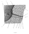
- FIG. 1 is a cross-sectional view of the tip portion of a liquid fuel injector nozzle having six spray holes 1 according to the present invention (four of which are shown).
- the tip portion comprises a hollow generally cylindrical nozzle body 3 which defines an internal fuel delivery chamber 5 which terminates at the tip portion of the injector in a sac 7.
- Each spray hole 1 has a hole entry 9 located in the sac 7 and a hole exit 11 located on the external surface of the nozzle body 3, so that fuel contained with the delivery chamber 5 can be injected out of the nozzle.
- valve needle (not shown) which is axially moveable within the chamber 5 and which in a first position seals against a valve seat 13 defined by the walls of the fuel delivery chamber 5, adjacent to the tip portion of the injector nozzle, in order to prevent fuel injection, and which is moveable away from the valve seat 13 in order to initiate fuel injection through the spray holes 1.
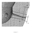
- a spray hole 1 according to the present invention is illustrated in greater detail in Figure 2 .
- the spray hole 1 can be divided along its length from hole entry 9 to hole exit 11 into 2 sections, a positively tapered hole entry section 15, to the inward side of line X-X and a negatively tapered hole exit section 17, to the outward side of line X-X.
- the positive sense means a reduction in diameter in the direction of fuel injection, i.e. from the sac 7 to the outside of the nozzle.
- the negative sense means a reduction in diameter in the opposite direction.
- Both the hole entry section 15 and the hole exit section 17 are frustoconical and are provided at each end with a radius.
- the hole entry section 15 is provided with a positive radius 19 at its end adjacent to the hole entry 9, and this joins section 15 to the wall of the sac 7.
- At the other end it is provided with a negative radius 21, which joins it to section 17.
- the terms 'positive radius' and 'negative radius' refer to radii which change the diameters of the hole entry and exit sections 15,17 in the same sense as the positive and negative tapers, as described previously. That is, a positive radius reduces the diameter of the section 15,17 in the direction of fuel injection and a negative radius increases the diameter of the section 15,17 in the direction of fuel injection.
- the hole exit section 17 is provided with a negative radius 23 where it joins with section 15 and a positive radius 25 where it joins the external surface of the nozzle.
- the aim of providing the above-described profile to a spray hole 1 is to improve the flow characteristics of fuel passing through it and to thus increase the efficiency of the fuel injection nozzle.
- any cavities that are created within the fuel flow, upon the fuel entering the spray hole 1, are compressed as the fuel moves along the positive, convergent, taper towards the intersection with hole exit section 17. This compression of the cavities suppresses any cavitation effects and hence improves the flow efficiency of the spray hole 1.
- the cavities within the fuel are able to expand as the fuel moves along the negative, divergent, taper towards the hole exit 11.
- the shape of the hole exit section 17, in particular the degree of taper, is chosen so that a controlled amount of cavitation is introduced to help clean the spray hole 1.
- the cavities are able to expand by such a degree that they collapse. The collapse of the cavities near the walls of the hole exit section 17 dislodges any deposits on the walls and hence the spray hole 1 is cleaned.
- the length of the section 17, designated by LN in Figure 3 is up to 30% of the length of the spray hole 1, designated by L in Figure 3
- the diameter of the hole exit 11, designated by D in Figure 2 is up to 40% larger than the diameter of the spray hole 1 at the intersection of the hole entry and the hole exit sections 15,17, designated by D2 in Figure 3 .
- the length LN is 15% to 25% of the length L and the diameter D is 20% to 30% larger than the diameter D2.
- the diameter, D1, of the hole entry 9 is 1.5 to 2.0 times larger than the diameter, D2, at the intersection of the hole entry section 15 and the hole exit section 17.
- the diameter of the hole entry section 15 at the wall of the sac 7, designated as D1 in Figure 3 is 0.125mm and the positive radius provided to section 15 is 0.03mm.
- the diameter, D, of the hole exit 9 is 0.155mm and the diameter, D2, at the intersection between sections 15,17 is 0.120mm.
- the length L of the spray hole 1 is 0.6mm and the length of section 17, LN, is 0.12mm.
- the profile of the spray hole 1 is created using an abrasive paste honing process in which an abrasive paste is forced through the spray hole 1.
- the abrasive paste is forced through the nozzle only in the direction of fuel injection, i.e. from the hole entry 9 towards the hole exit 11. This is used to create a smooth flow path, in particular the positive radius 19 on the section 15.
- the amount of honing applied determines the size of the radii and the degree of taper imparted to the hole entry section 15 and the hole exit section 17.
- Spray holes 1 according to the present invention can equally be applied to any other appropriate liquid fuel injector, for example an injector of Valve Covers Orifice type.
Landscapes
- Engineering & Computer Science (AREA)
- Chemical & Material Sciences (AREA)
- Combustion & Propulsion (AREA)
- Mechanical Engineering (AREA)
- General Engineering & Computer Science (AREA)
- Fuel-Injection Apparatus (AREA)
Claims (11)
- Flüssigkraftstoff-Einspritzvorrichtung für eine Brennkraftmaschine, die einen Düsenkörper (3) mit wenigstens einem Sprühloch (1) aufweist, wobei das wenigstens eine Sprühloch (1) einen Locheintritt (9) an der Innenseite des Düsenkörpers und einen Lochaustritt (11) an der Außenseite des Düsenkörpers (3) hat und das Sprühloch (1) mit einem Locheintrittsabschnitt (15) versehen ist, der, angefangen am Locheintritt (9), einen Durchflussbereich hat, der sich von einem Bereich mit relativ größerem Durchfluss am Locheintritt (9) auf einen Bereich mit relativ kleinem Durchfluss am Schnitt zwischen dem Ende des Locheintrittsabschnitts (15) und dem Anfang eines Lochaustrittabschnitts (17) verkleinert, wobei der Lochaustrittsabschnitt (17), angefangen am Schnitt mit dem Locheintrittsabschnitt (15), einen Durchflussbereich hat, der sich von einem Bereich mit relativ kleinem Durchfluss am Schnitt mit dem Locheintrittsabschnitt (15) auf einen Bereich mit relativ großem Durchfluss am Lochaustritt (11) vergrößert, wobei der Locheintrittsabschnitt (15) und der Lochaustrittsabschnitt (17) einen im Wesentlichen kreisförmigen Querschnitt haben und der Durchmesser des Locheintrittsabschnitts (15) und des Lochaustrittsabschnitts (17) jeweils in einer im Wesentlichen linearen Beziehung im Verhältnis zur Entfernung am jeweiligen Abschnitt (15, 17) entlang variiert, und dadurch gekennzeichnet, dass das Ende des Locheintrittsabschnitts und der Anfang des Lochaustrittsabschnitts den gleichen Durchmesser haben.
- Flüssigkraftstoff-Einspritzvorrichtung nach Anspruch 1, wobei der Locheintritt (9) und der Lochaustritt (11) mit einem Radius versehen sind.
- Flüssigkraftstoff-Einspritzvorrichtung nach Anspruch 1 oder Anspruch 2, wobei der Schnitt zwischen dem Locheintrittsabschnitt (15) und dem Lochaustrittsabschnitt (17) mit einem Radius versehen ist.
- Flüssigkraftstoff-Einspritzvorrichtung nach einem der vorhergehenden Ansprüche, wobei die Länge (LN) des Lochaustrittsabschnitts (17) bis zu 30 % der Länge (L) des Sprühlochs (1) ist.
- Flüssigkraftstoff-Einspritzvorrichtung nach einem der vorhergehenden Ansprüche, wobei die Länge (LN) des Lochaustrittsabschnitts (17) zwischen 15 % und 25 % der Länge (L) des Sprühlochs (1) ist.
- Flüssigkraftstoff-Einspritzvorrichtung nach einem der vorhergehenden Ansprüche, wobei der Durchmesser (D) des Lochaustritts (11) bis zu 40 % größer als der Durchmesser (D2) am Schnitt zwischen dem Locheintrittsabschnitt (15) und dem Lochaustrittsabschnitt (17) ist.
- Flüssigkraftstoff-Einspritzvorrichtung nach einem der vorhergehenden Ansprüche, wobei der Durchmesser (D) des Lochaustritts (11) zwischen 20 % und 30 % größer als der Durchmesser (D2) am Schnitt zwischen dem Locheintrittsabschnitt (15) und dem Lochaustrittsabschnitt (17) ist.
- Flüssigkraftstoff-Einspritzvorrichtung nach einem der vorhergehenden Ansprüche, wobei der Durchmesser (D1) des Locheintritts (9) 1,5- bis 2,5-mal größer als der Durchmesser (D2) am Schnitt zwischen dem Locheintrittsabschnitt (15) und dem Lochaustrittsabschnitt (17) ist.
- Verfahren zum Herstellen eines Sprühlochs (1) in einer Flüssigkraftstoff-Einspritzvorrichtung nach einem der vorhergehenden Ansprüche, das ein abtragendes Honverfahren nutzt, bei dem ein Fluidträger, der Schleifmittel enthält, einmal in einer Richtung von dem Locheintritt (9) zum Lochaustritt (11) hin durch das Sprühloch (1) hindurchgeführt wird, um einen Locheintrittsabschnitt mit einer konvergierenden konischen Form zu schaffen, und ein andermal in einer Richtung von dem Lochaustritt (11) zum Locheintritt (9) hin hindurchgeführt wird, um einen Lochaustrittsabschnitt mit einer divergierenden konischen Form zu schaffen.
- Verfahren nach Anspruch 9, wobei der Träger eine Paste ist.
- Verfahren nach Anspruch 9, wobei der Träger Wasser ist.
Applications Claiming Priority (1)
| Application Number | Priority Date | Filing Date | Title |
|---|---|---|---|
| GBGB0712403.5A GB0712403D0 (en) | 2007-06-26 | 2007-06-26 | A Spray Hole Profile |
Publications (2)
| Publication Number | Publication Date |
|---|---|
| EP2009276A1 EP2009276A1 (de) | 2008-12-31 |
| EP2009276B1 true EP2009276B1 (de) | 2012-09-12 |
Family
ID=38352966
Family Applications (1)
| Application Number | Title | Priority Date | Filing Date |
|---|---|---|---|
| EP08159065A Active EP2009276B1 (de) | 2007-06-26 | 2008-06-26 | Sprühlochprofil |
Country Status (4)
| Country | Link |
|---|---|
| US (1) | US8544770B2 (de) |
| EP (1) | EP2009276B1 (de) |
| JP (1) | JP2009008087A (de) |
| GB (1) | GB0712403D0 (de) |
Families Citing this family (31)
| Publication number | Priority date | Publication date | Assignee | Title |
|---|---|---|---|---|
| DE102008055069A1 (de) * | 2008-12-22 | 2010-07-01 | Robert Bosch Gmbh | Kraftstoffeinspritzventil für Brennkraftmaschinen |
| WO2010121767A1 (de) * | 2009-04-20 | 2010-10-28 | Prelatec Gmbh | Düse mit mindestens einem spritzloch zum zerstäuben von fluiden |
| KR20180001595A (ko) | 2009-07-30 | 2018-01-04 | 쓰리엠 이노베이티브 프로퍼티즈 컴파니 | 노즐 및 그 제조 방법 |
| US20110030635A1 (en) * | 2009-08-04 | 2011-02-10 | International Engine Intellectual Property Company, Llc | Fuel injector nozzle for reduced coking |
| EP2365207A1 (de) * | 2010-03-09 | 2011-09-14 | EFI Hightech AG | Einspritzdüse für eine verbrennungskraftmaschine |
| KR101198805B1 (ko) * | 2010-12-02 | 2012-11-07 | 현대자동차주식회사 | 차량용 인젝터 |
| CH704964A1 (de) * | 2011-05-16 | 2012-11-30 | Liebherr Machines Bulle Sa | Düse. |
| US9762246B2 (en) * | 2011-05-20 | 2017-09-12 | Semiconductor Energy Laboratory Co., Ltd. | Semiconductor device with a storage circuit having an oxide semiconductor |
| AT512423A1 (de) * | 2012-02-07 | 2013-08-15 | Bosch Gmbh Robert | Einspritzdüse zum einspritzen von medien in den brennraum einer brennkraftmaschine |
| JP5959892B2 (ja) | 2012-03-26 | 2016-08-02 | 日立オートモティブシステムズ株式会社 | 火花点火式燃料噴射弁 |
| US9546633B2 (en) * | 2012-03-30 | 2017-01-17 | Electro-Motive Diesel, Inc. | Nozzle for skewed fuel injection |
| JP6186130B2 (ja) * | 2013-02-04 | 2017-08-23 | 日立オートモティブシステムズ株式会社 | 燃料噴射弁及び燃料噴射弁の製造方法 |
| US9797296B2 (en) * | 2013-03-15 | 2017-10-24 | Cummins Inc. | Pre-chamber for internal combustion engine |
| JP6020380B2 (ja) * | 2013-08-02 | 2016-11-02 | 株式会社デンソー | 燃料噴射弁 |
| JP6109758B2 (ja) * | 2014-01-30 | 2017-04-05 | 株式会社日本自動車部品総合研究所 | 燃料噴射ノズル |
| JP6160564B2 (ja) * | 2014-06-09 | 2017-07-12 | マツダ株式会社 | ディーゼルエンジン |
| JP6264221B2 (ja) * | 2014-07-24 | 2018-01-24 | 株式会社デンソー | 燃料噴射ノズル |
| US9909549B2 (en) * | 2014-10-01 | 2018-03-06 | National Technology & Engineering Solutions Of Sandia, Llc | Ducted fuel injection |
| DE112015004524B4 (de) * | 2014-10-02 | 2025-10-09 | Cummins Inc. | Kraftstoffeinspritzdüse mit Düse variabler Lochgröße und Sprühwinkel und MHBIB |
| US9556844B2 (en) * | 2015-02-13 | 2017-01-31 | Caterpillar Inc. | Nozzle with contoured orifice surface and method of making same |
| JP6460858B2 (ja) * | 2015-03-17 | 2019-01-30 | 株式会社エンプラス | 燃料噴射装置用ノズルプレート |
| JP6254122B2 (ja) * | 2015-06-24 | 2017-12-27 | 株式会社デンソー | 燃料噴射ノズル |
| US9915190B2 (en) | 2015-07-13 | 2018-03-13 | Caterpillar, Inc. | Ducted combustion systems utilizing Venturi ducts |
| WO2017031598A1 (en) * | 2015-08-27 | 2017-03-02 | Westport Power Inc. | Deposit mitigation for gaseous fuel injectors |
| SE539875C2 (en) * | 2015-09-14 | 2017-12-27 | Scania Cv Ab | A fuel injector |
| CN109070253B (zh) | 2015-10-23 | 2021-02-12 | 康明斯公司 | 用于产生可变喷射孔几何形状的放电加工方法 |
| US20170211480A1 (en) * | 2016-01-21 | 2017-07-27 | Delavan Inc | Discrete jet orifices |
| JP6339628B2 (ja) * | 2016-06-22 | 2018-06-06 | 日立オートモティブシステムズ株式会社 | 燃料噴射弁 |
| WO2019030078A1 (en) * | 2017-08-08 | 2019-02-14 | Robert Bosch Gmbh | FUEL INJECTOR NOZZLE |
| WO2020085039A1 (ja) * | 2018-10-26 | 2020-04-30 | 日立オートモティブシステムズ株式会社 | 燃料噴射弁 |
| DE112021000752T5 (de) | 2020-03-31 | 2022-11-24 | Cummins Inc. | Spray-Loch einer Einspritzdüse mit Venturi- und Luftmitreißelement |
Citations (1)
| Publication number | Priority date | Publication date | Assignee | Title |
|---|---|---|---|---|
| US20010025892A1 (en) * | 1999-12-03 | 2001-10-04 | Mccoy James J. | Supersonic injector for gas engine |
Family Cites Families (28)
| Publication number | Priority date | Publication date | Assignee | Title |
|---|---|---|---|---|
| US406978A (en) * | 1889-07-16 | Underground conduit | ||
| DE2557772A1 (de) * | 1975-12-20 | 1977-06-23 | Kloeckner Humboldt Deutz Ag | Brennstoffeinspritzventil |
| DE3723698C2 (de) * | 1987-07-17 | 1995-04-27 | Bosch Gmbh Robert | Kraftstoffeinspritzventil sowie Verfahren zu dessen Einstellung |
| GB8817774D0 (en) | 1988-07-26 | 1988-09-01 | Lucas Ind Plc | Fuel injectors for i c engines |
| GB8827107D0 (en) * | 1988-11-19 | 1988-12-21 | Lucas Ind Plc | Fuel injection nozzle |
| DE4202752A1 (de) * | 1992-01-31 | 1993-08-05 | Bosch Gmbh Robert | Kraftstoffeinspritzduese fuer brennkraftmaschinen |
| DE4409848A1 (de) * | 1994-03-22 | 1995-10-19 | Siemens Ag | Vorrichtung zur Zumessung und Zerstäubung von Fluiden |
| DE19507171C1 (de) * | 1995-03-02 | 1996-08-14 | Bosch Gmbh Robert | Kraftstoffeinspritzventil für Brennkraftmaschinen |
| JP3757453B2 (ja) * | 1996-02-07 | 2006-03-22 | 株式会社デンソー | 燃料噴射ノズルの噴孔加工方法 |
| EP0809017A1 (de) | 1996-05-22 | 1997-11-26 | Steyr-Daimler-Puch Aktiengesellschaft | Zweistufige Kraftstoffeinspritzdüse für Brennkraftmaschinen |
| DE19847460A1 (de) | 1998-10-15 | 2000-04-20 | Bosch Gmbh Robert | Kraftstoffeinspritzdüse für selbstzündende Brennkraftmaschinen |
| US6644565B2 (en) * | 1998-10-15 | 2003-11-11 | Robert Bosch Gmbh | Fuel injection nozzle for self-igniting internal combustion engines |
| DE19914719C2 (de) | 1999-03-31 | 2001-05-03 | Siemens Ag | Vorrichtung zum hydroerosiven Runden von Einlaufkanten der Spritzlochkanäle in einem Düsenkörper |
| DE19931890A1 (de) * | 1999-07-08 | 2001-01-18 | Siemens Ag | Düsenkörper für eine Kraftstoffeinspritzdüse mit optimierter Spritzlochkanalgeometrie |
| JP3837282B2 (ja) * | 2000-10-24 | 2006-10-25 | 株式会社ケーヒン | 燃料噴射弁 |
| DE10105674A1 (de) | 2001-02-08 | 2002-08-29 | Siemens Ag | Kraftstoffeinspritzdüse für eine Brennkraftmaschine |
| DE10106809A1 (de) | 2001-02-14 | 2002-09-19 | Siemens Ag | Verfahren zur Herstellung eines Lochs in einem Körper, insbesondere eines Einspritzlochs in einem Kraftstoffinjektor |
| JP2003120472A (ja) | 2001-10-11 | 2003-04-23 | Denso Corp | 燃料噴射ノズル |
| US7191961B2 (en) | 2002-11-29 | 2007-03-20 | Denso Corporation | Injection hole plate and fuel injection apparatus having the same |
| JP4058377B2 (ja) * | 2003-05-09 | 2008-03-05 | 株式会社デンソー | 燃料噴射弁 |
| DE10329731A1 (de) * | 2003-07-02 | 2005-02-03 | Robert Bosch Gmbh | Kraftstoffeinspritzventil und ein Verfahren zur Herstellung desselben |
| DE10353168A1 (de) | 2003-11-14 | 2005-06-23 | Robert Bosch Gmbh | Verfahren und Vorrichtung zum hydroerosiven Verrunden von Bohrungsübergängen |
| JP4222256B2 (ja) * | 2004-05-20 | 2009-02-12 | 株式会社デンソー | 内燃機関の制御装置 |
| JP2006057564A (ja) * | 2004-08-20 | 2006-03-02 | Aisan Ind Co Ltd | 燃料噴射弁 |
| US7438241B2 (en) * | 2004-11-05 | 2008-10-21 | Visteon Global Technologies, Inc. | Low pressure fuel injector nozzle |
| US7185831B2 (en) * | 2004-11-05 | 2007-03-06 | Ford Motor Company | Low pressure fuel injector nozzle |
| US8976858B2 (en) | 2005-05-13 | 2015-03-10 | Qualcomm Incorporated | Error resilience using out of band directory information |
| JP2007051589A (ja) * | 2005-08-18 | 2007-03-01 | Denso Corp | 内燃機関の燃料噴射装置 |
-
2007
- 2007-06-26 GB GBGB0712403.5A patent/GB0712403D0/en not_active Ceased
-
2008
- 2008-06-26 EP EP08159065A patent/EP2009276B1/de active Active
- 2008-06-26 JP JP2008167668A patent/JP2009008087A/ja active Pending
- 2008-06-26 US US12/215,375 patent/US8544770B2/en active Active
Patent Citations (1)
| Publication number | Priority date | Publication date | Assignee | Title |
|---|---|---|---|---|
| US20010025892A1 (en) * | 1999-12-03 | 2001-10-04 | Mccoy James J. | Supersonic injector for gas engine |
Also Published As
| Publication number | Publication date |
|---|---|
| US8544770B2 (en) | 2013-10-01 |
| GB0712403D0 (en) | 2007-08-01 |
| JP2009008087A (ja) | 2009-01-15 |
| EP2009276A1 (de) | 2008-12-31 |
| US20090020633A1 (en) | 2009-01-22 |
Similar Documents
| Publication | Publication Date | Title |
|---|---|---|
| US8544770B2 (en) | Spray hole profile | |
| EP1076772B1 (de) | Kraftstoffeinspritzdüse für eine brennkraftmaschine | |
| JP6264221B2 (ja) | 燃料噴射ノズル | |
| JPH03182682A (ja) | 燃料噴射弁 | |
| US20110215177A1 (en) | Injection nozzle | |
| GB2386156A (en) | Fuel injector nozzle assembly having a nozzle plate with projections to induce turbulence | |
| WO2011117113A1 (en) | Injection nozzle | |
| JP2010048237A (ja) | 燃料噴射ノズルおよびその製造方法 | |
| CN101240763B (zh) | 燃料喷射阀 | |
| JP2010222977A (ja) | 燃料噴射ノズル | |
| US8905333B1 (en) | Diesel injector and method utilizing focused supercavitation to reduce spray penetration length | |
| KR100627745B1 (ko) | 자가 점화식 엔진용 연료 분사 노즐 | |
| CN1771390A (zh) | 用于内燃机的燃料喷射阀 | |
| KR100440828B1 (ko) | 내연기관, 특히 대형의 저속 선박디젤엔진용 연료 분사펌프 | |
| CN101871412B (zh) | 内燃机的喷油嘴 | |
| WO2020056270A1 (en) | Nozzle with counterbored through-hole | |
| JP6609196B2 (ja) | 燃料噴射ノズル | |
| US12049860B2 (en) | Nozzle for a fuel injector | |
| EP2292918B1 (de) | Brennstoffeinspritzvorrichtung mit Mess-Servoventil für einen Verbrennungsmotor | |
| JP2005180375A (ja) | 燃料噴射ノズル | |
| US7490784B2 (en) | Injector for injecting fuel | |
| EP1307650B1 (de) | Brennstoffeinspritzventil | |
| EP2347115B1 (de) | Injektor zur einspritzung von mit hochdruck beaufschlagtem kraftstoff in den brennraum einer brennkraftmaschine | |
| CN106286056A (zh) | 燃料喷射喷嘴 | |
| CN104929837B (zh) | 一种气液两态混合喷射的柴油喷油嘴 |
Legal Events
| Date | Code | Title | Description |
|---|---|---|---|
| PUAI | Public reference made under article 153(3) epc to a published international application that has entered the european phase |
Free format text: ORIGINAL CODE: 0009012 |
|
| AK | Designated contracting states |
Kind code of ref document: A1 Designated state(s): AT BE BG CH CY CZ DE DK EE ES FI FR GB GR HR HU IE IS IT LI LT LU LV MC MT NL NO PL PT RO SE SI SK TR |
|
| AX | Request for extension of the european patent |
Extension state: AL BA MK RS |
|
| 17P | Request for examination filed |
Effective date: 20090630 |
|
| 17Q | First examination report despatched |
Effective date: 20090731 |
|
| AKX | Designation fees paid |
Designated state(s): AT BE BG CH CY CZ DE DK EE ES FI FR GB GR HR HU IE IS IT LI LT LU LV MC MT NL NO PL PT RO SE SI SK TR |
|
| AXX | Extension fees paid |
Extension state: AL Payment date: 20090630 Extension state: MK Payment date: 20090630 Extension state: BA Payment date: 20090630 Extension state: RS Payment date: 20090630 |
|
| RAP1 | Party data changed (applicant data changed or rights of an application transferred) |
Owner name: DELPHI TECHNOLOGIES HOLDING S.A.R.L. |
|
| GRAP | Despatch of communication of intention to grant a patent |
Free format text: ORIGINAL CODE: EPIDOSNIGR1 |
|
| GRAS | Grant fee paid |
Free format text: ORIGINAL CODE: EPIDOSNIGR3 |
|
| GRAA | (expected) grant |
Free format text: ORIGINAL CODE: 0009210 |
|
| AK | Designated contracting states |
Kind code of ref document: B1 Designated state(s): AT BE BG CH CY CZ DE DK EE ES FI FR GB GR HR HU IE IS IT LI LT LU LV MC MT NL NO PL PT RO SE SI SK TR |
|
| AX | Request for extension of the european patent |
Extension state: AL BA MK RS |
|
| REG | Reference to a national code |
Ref country code: GB Ref legal event code: FG4D |
|
| REG | Reference to a national code |
Ref country code: CH Ref legal event code: EP |
|
| REG | Reference to a national code |
Ref country code: AT Ref legal event code: REF Ref document number: 575218 Country of ref document: AT Kind code of ref document: T Effective date: 20120915 |
|
| REG | Reference to a national code |
Ref country code: IE Ref legal event code: FG4D |
|
| REG | Reference to a national code |
Ref country code: DE Ref legal event code: R096 Ref document number: 602008018673 Country of ref document: DE Effective date: 20121108 |
|
| PG25 | Lapsed in a contracting state [announced via postgrant information from national office to epo] |
Ref country code: LT Free format text: LAPSE BECAUSE OF FAILURE TO SUBMIT A TRANSLATION OF THE DESCRIPTION OR TO PAY THE FEE WITHIN THE PRESCRIBED TIME-LIMIT Effective date: 20120912 Ref country code: HR Free format text: LAPSE BECAUSE OF FAILURE TO SUBMIT A TRANSLATION OF THE DESCRIPTION OR TO PAY THE FEE WITHIN THE PRESCRIBED TIME-LIMIT Effective date: 20120912 Ref country code: FI Free format text: LAPSE BECAUSE OF FAILURE TO SUBMIT A TRANSLATION OF THE DESCRIPTION OR TO PAY THE FEE WITHIN THE PRESCRIBED TIME-LIMIT Effective date: 20120912 Ref country code: NO Free format text: LAPSE BECAUSE OF FAILURE TO SUBMIT A TRANSLATION OF THE DESCRIPTION OR TO PAY THE FEE WITHIN THE PRESCRIBED TIME-LIMIT Effective date: 20121212 |
|
| REG | Reference to a national code |
Ref country code: NL Ref legal event code: VDEP Effective date: 20120912 |
|
| REG | Reference to a national code |
Ref country code: AT Ref legal event code: MK05 Ref document number: 575218 Country of ref document: AT Kind code of ref document: T Effective date: 20120912 |
|
| REG | Reference to a national code |
Ref country code: LT Ref legal event code: MG4D Effective date: 20120912 |
|
| PG25 | Lapsed in a contracting state [announced via postgrant information from national office to epo] |
Ref country code: GR Free format text: LAPSE BECAUSE OF FAILURE TO SUBMIT A TRANSLATION OF THE DESCRIPTION OR TO PAY THE FEE WITHIN THE PRESCRIBED TIME-LIMIT Effective date: 20121213 Ref country code: LV Free format text: LAPSE BECAUSE OF FAILURE TO SUBMIT A TRANSLATION OF THE DESCRIPTION OR TO PAY THE FEE WITHIN THE PRESCRIBED TIME-LIMIT Effective date: 20120912 Ref country code: SI Free format text: LAPSE BECAUSE OF FAILURE TO SUBMIT A TRANSLATION OF THE DESCRIPTION OR TO PAY THE FEE WITHIN THE PRESCRIBED TIME-LIMIT Effective date: 20120912 Ref country code: SE Free format text: LAPSE BECAUSE OF FAILURE TO SUBMIT A TRANSLATION OF THE DESCRIPTION OR TO PAY THE FEE WITHIN THE PRESCRIBED TIME-LIMIT Effective date: 20120912 |
|
| PG25 | Lapsed in a contracting state [announced via postgrant information from national office to epo] |
Ref country code: BE Free format text: LAPSE BECAUSE OF FAILURE TO SUBMIT A TRANSLATION OF THE DESCRIPTION OR TO PAY THE FEE WITHIN THE PRESCRIBED TIME-LIMIT Effective date: 20120912 Ref country code: IS Free format text: LAPSE BECAUSE OF FAILURE TO SUBMIT A TRANSLATION OF THE DESCRIPTION OR TO PAY THE FEE WITHIN THE PRESCRIBED TIME-LIMIT Effective date: 20130112 Ref country code: RO Free format text: LAPSE BECAUSE OF FAILURE TO SUBMIT A TRANSLATION OF THE DESCRIPTION OR TO PAY THE FEE WITHIN THE PRESCRIBED TIME-LIMIT Effective date: 20120912 Ref country code: NL Free format text: LAPSE BECAUSE OF FAILURE TO SUBMIT A TRANSLATION OF THE DESCRIPTION OR TO PAY THE FEE WITHIN THE PRESCRIBED TIME-LIMIT Effective date: 20120912 Ref country code: CZ Free format text: LAPSE BECAUSE OF FAILURE TO SUBMIT A TRANSLATION OF THE DESCRIPTION OR TO PAY THE FEE WITHIN THE PRESCRIBED TIME-LIMIT Effective date: 20120912 Ref country code: EE Free format text: LAPSE BECAUSE OF FAILURE TO SUBMIT A TRANSLATION OF THE DESCRIPTION OR TO PAY THE FEE WITHIN THE PRESCRIBED TIME-LIMIT Effective date: 20120912 |
|
| PG25 | Lapsed in a contracting state [announced via postgrant information from national office to epo] |
Ref country code: SK Free format text: LAPSE BECAUSE OF FAILURE TO SUBMIT A TRANSLATION OF THE DESCRIPTION OR TO PAY THE FEE WITHIN THE PRESCRIBED TIME-LIMIT Effective date: 20120912 Ref country code: PL Free format text: LAPSE BECAUSE OF FAILURE TO SUBMIT A TRANSLATION OF THE DESCRIPTION OR TO PAY THE FEE WITHIN THE PRESCRIBED TIME-LIMIT Effective date: 20120912 Ref country code: PT Free format text: LAPSE BECAUSE OF FAILURE TO SUBMIT A TRANSLATION OF THE DESCRIPTION OR TO PAY THE FEE WITHIN THE PRESCRIBED TIME-LIMIT Effective date: 20130114 Ref country code: CY Free format text: LAPSE BECAUSE OF FAILURE TO SUBMIT A TRANSLATION OF THE DESCRIPTION OR TO PAY THE FEE WITHIN THE PRESCRIBED TIME-LIMIT Effective date: 20120912 |
|
| PG25 | Lapsed in a contracting state [announced via postgrant information from national office to epo] |
Ref country code: AT Free format text: LAPSE BECAUSE OF FAILURE TO SUBMIT A TRANSLATION OF THE DESCRIPTION OR TO PAY THE FEE WITHIN THE PRESCRIBED TIME-LIMIT Effective date: 20120912 |
|
| PLBE | No opposition filed within time limit |
Free format text: ORIGINAL CODE: 0009261 |
|
| STAA | Information on the status of an ep patent application or granted ep patent |
Free format text: STATUS: NO OPPOSITION FILED WITHIN TIME LIMIT |
|
| PG25 | Lapsed in a contracting state [announced via postgrant information from national office to epo] |
Ref country code: DK Free format text: LAPSE BECAUSE OF FAILURE TO SUBMIT A TRANSLATION OF THE DESCRIPTION OR TO PAY THE FEE WITHIN THE PRESCRIBED TIME-LIMIT Effective date: 20120912 Ref country code: BG Free format text: LAPSE BECAUSE OF FAILURE TO SUBMIT A TRANSLATION OF THE DESCRIPTION OR TO PAY THE FEE WITHIN THE PRESCRIBED TIME-LIMIT Effective date: 20121212 |
|
| 26N | No opposition filed |
Effective date: 20130613 |
|
| PG25 | Lapsed in a contracting state [announced via postgrant information from national office to epo] |
Ref country code: IT Free format text: LAPSE BECAUSE OF FAILURE TO SUBMIT A TRANSLATION OF THE DESCRIPTION OR TO PAY THE FEE WITHIN THE PRESCRIBED TIME-LIMIT Effective date: 20120912 |
|
| REG | Reference to a national code |
Ref country code: DE Ref legal event code: R097 Ref document number: 602008018673 Country of ref document: DE Effective date: 20130613 |
|
| PG25 | Lapsed in a contracting state [announced via postgrant information from national office to epo] |
Ref country code: ES Free format text: LAPSE BECAUSE OF FAILURE TO SUBMIT A TRANSLATION OF THE DESCRIPTION OR TO PAY THE FEE WITHIN THE PRESCRIBED TIME-LIMIT Effective date: 20121223 |
|
| PG25 | Lapsed in a contracting state [announced via postgrant information from national office to epo] |
Ref country code: MC Free format text: LAPSE BECAUSE OF FAILURE TO SUBMIT A TRANSLATION OF THE DESCRIPTION OR TO PAY THE FEE WITHIN THE PRESCRIBED TIME-LIMIT Effective date: 20120912 |
|
| REG | Reference to a national code |
Ref country code: CH Ref legal event code: PL |
|
| GBPC | Gb: european patent ceased through non-payment of renewal fee |
Effective date: 20130626 |
|
| REG | Reference to a national code |
Ref country code: IE Ref legal event code: MM4A |
|
| PG25 | Lapsed in a contracting state [announced via postgrant information from national office to epo] |
Ref country code: CH Free format text: LAPSE BECAUSE OF NON-PAYMENT OF DUE FEES Effective date: 20130630 Ref country code: GB Free format text: LAPSE BECAUSE OF NON-PAYMENT OF DUE FEES Effective date: 20130626 Ref country code: LI Free format text: LAPSE BECAUSE OF NON-PAYMENT OF DUE FEES Effective date: 20130630 Ref country code: IE Free format text: LAPSE BECAUSE OF NON-PAYMENT OF DUE FEES Effective date: 20130626 |
|
| REG | Reference to a national code |
Ref country code: FR Ref legal event code: TP Owner name: DELPHI INTERNATIONAL OPERATIONS LUXEMBOURG S.A, LU Effective date: 20140516 |
|
| REG | Reference to a national code |
Ref country code: DE Ref legal event code: R081 Ref document number: 602008018673 Country of ref document: DE Owner name: DELPHI INTERNATIONAL OPERATIONS LUXEMBOURG S.A, LU Free format text: FORMER OWNER: DELPHI TECHNOLOGIES HOLDING S.A.R.L., BASCHARAGE, LU Effective date: 20140702 |
|
| PG25 | Lapsed in a contracting state [announced via postgrant information from national office to epo] |
Ref country code: MT Free format text: LAPSE BECAUSE OF FAILURE TO SUBMIT A TRANSLATION OF THE DESCRIPTION OR TO PAY THE FEE WITHIN THE PRESCRIBED TIME-LIMIT Effective date: 20120912 |
|
| PG25 | Lapsed in a contracting state [announced via postgrant information from national office to epo] |
Ref country code: TR Free format text: LAPSE BECAUSE OF FAILURE TO SUBMIT A TRANSLATION OF THE DESCRIPTION OR TO PAY THE FEE WITHIN THE PRESCRIBED TIME-LIMIT Effective date: 20120912 |
|
| PG25 | Lapsed in a contracting state [announced via postgrant information from national office to epo] |
Ref country code: LU Free format text: LAPSE BECAUSE OF NON-PAYMENT OF DUE FEES Effective date: 20130626 Ref country code: HU Free format text: LAPSE BECAUSE OF FAILURE TO SUBMIT A TRANSLATION OF THE DESCRIPTION OR TO PAY THE FEE WITHIN THE PRESCRIBED TIME-LIMIT; INVALID AB INITIO Effective date: 20080626 |
|
| REG | Reference to a national code |
Ref country code: FR Ref legal event code: PLFP Year of fee payment: 9 |
|
| REG | Reference to a national code |
Ref country code: FR Ref legal event code: PLFP Year of fee payment: 10 |
|
| REG | Reference to a national code |
Ref country code: FR Ref legal event code: PLFP Year of fee payment: 11 |
|
| REG | Reference to a national code |
Ref country code: DE Ref legal event code: R081 Ref document number: 602008018673 Country of ref document: DE Owner name: DELPHI TECHNOLOGIES IP LIMITED, BB Free format text: FORMER OWNER: DELPHI INTERNATIONAL OPERATIONS LUXEMBOURG S.A R.L., BASCHARAGE, LU |
|
| P01 | Opt-out of the competence of the unified patent court (upc) registered |
Effective date: 20230327 |
|
| REG | Reference to a national code |
Ref country code: DE Ref legal event code: R081 Ref document number: 602008018673 Country of ref document: DE Owner name: PHINIA DELPHI LUXEMBOURG SARL, LU Free format text: FORMER OWNER: DELPHI TECHNOLOGIES IP LIMITED, ST. MICHAEL, BB |
|
| PGFP | Annual fee paid to national office [announced via postgrant information from national office to epo] |
Ref country code: DE Payment date: 20250509 Year of fee payment: 18 |
|
| PGFP | Annual fee paid to national office [announced via postgrant information from national office to epo] |
Ref country code: FR Payment date: 20250512 Year of fee payment: 18 |