EP2009157B1 - Dispositif d'accouplement pour un cadre à lisses - Google Patents
Dispositif d'accouplement pour un cadre à lisses Download PDFInfo
- Publication number
- EP2009157B1 EP2009157B1 EP07012444A EP07012444A EP2009157B1 EP 2009157 B1 EP2009157 B1 EP 2009157B1 EP 07012444 A EP07012444 A EP 07012444A EP 07012444 A EP07012444 A EP 07012444A EP 2009157 B1 EP2009157 B1 EP 2009157B1
- Authority
- EP
- European Patent Office
- Prior art keywords
- heald frame
- push rod
- side support
- connecting means
- frame connecting
- Prior art date
- Legal status (The legal status is an assumption and is not a legal conclusion. Google has not performed a legal analysis and makes no representation as to the accuracy of the status listed.)
- Expired - Fee Related
Links
Images


Classifications
-
- D—TEXTILES; PAPER
- D03—WEAVING
- D03C—SHEDDING MECHANISMS; PATTERN CARDS OR CHAINS; PUNCHING OF CARDS; DESIGNING PATTERNS
- D03C9/00—Healds; Heald frames
- D03C9/06—Heald frames
- D03C9/0608—Construction of frame parts
- D03C9/065—Side stays
-
- D—TEXTILES; PAPER
- D03—WEAVING
- D03C—SHEDDING MECHANISMS; PATTERN CARDS OR CHAINS; PUNCHING OF CARDS; DESIGNING PATTERNS
- D03C9/00—Healds; Heald frames
- D03C9/06—Heald frames
- D03C9/0683—Arrangements or means for the linking to the drive system
Definitions
- the invention relates to a shank connection device for a heald of a weaving machine.
- Weaving machines usually have a plurality of healds, which are formed by a substantially rectangular frame that holds a large number of healds.
- the heald frames usually each have two, in use, horizontally held shaft rods connected at their ends by vertically oriented side supports. These units are moved vertically up and down by a shaft drive.
- Such a hive is eg. The US 6,378,564 B1 refer to.
- To move the heald vertically its two side supports are connected at their respective upper end with a push rod.
- the push rod is connected to the carriage of a vertical guide.
- the side support of the heald is also connected via a suitable hook to the carriage of the vertical guide.
- heald frames must occasionally be removed from the weaving machine and reinserted there. To do this, loosen the connection between the push rod and the side support. This should be as simple as possible and can be done in a few simple steps. On the other hand, the connection must also be safe to produce again.
- the JP 9-21030 A discloses a heddle having vertically displaceably guided side supports.
- the side supports are braced at their upper ends with Befest Trentsklötzen.
- the free threaded upper ends of push rods are inserted into these clamping blocks and screwed by nuts with these.
- the push rods are guided separately and spaced from the side supports.
- a different concept illustrates the utility model DE 91 03 031 U1 , It starts from a weave, which is moved up and down by traction means.
- the traction means are, for example, formed by ropes.
- At the upper end of the side support is used for movement and guidance of the heald a traction means which is secured there by means of a clamping device.
- heald frames with hollow side supports, through the interior of each extending a drive rod in the vertical direction.
- the push rod is provided at its lower end with a screw thread, which is bolted to the side support.
- a screw thread is provided at the upper end of the side support, the end face rests on the front side of the push rod.
- the Japanese tested utility model JP 06-38124 Y2 teaches to design a push rod so that it can receive the side support of a heald form-fitting manner.
- a clasp with clamping screw is used to attach or loosen the heald.
- the push rod is guided by fixed guides and thus takes over the leadership of the webshaft. A height adjustment of the shaft from above is not possible.
- the shank connection device includes a vertically positioned side support and a push rod having an upper free end, the push rod being driven vertically up and down in use at its lower end and resting against the side support over most of its length.
- the push rod is stabilized and guided by the side support.
- it may extend for this purpose through a cavity or interior of the side support, wherein it the cavity surrounding the inside of the side support abuts. But it may also be hollow, for example, in cross-section U-shaped and embrace the side support. In both cases, the push rod and the side support embrace each other. They are mutually supportive.
- a particularly simple embodiment of the invention results when the push rod has a rectangular cross-section with two flat sides facing away from each other, which bear against two opposite inner sides of the side support, and when the push rod can move along these inner sides oscillating.
- a certain flexibility of the push rod then allows a flexible deflection of the push rod in the direction of the long narrow sides of its rectangular cross section. On the one hand, therefore, a secure thrust transfer is possible, on the other hand, the push rod can be connected without an intermediate guide to a moving on an arcuate path joint.
- a clamping device is arranged at the upper end of the side support, preferably above the upper connection of the side support with the shaft rod, which serves to clamp the side support to the upper free end of the push rod.
- the adjustment means is assigned to the side support. If the side support and push rod are separated from one another, eg to remove the heald from the weaving machine, the adjusting means, for example in the form of a clamping device, remain on the side support.
- Slings on the side support and / or the push rod limit the introduction of a heald shaft down into the weaving machine. These slings also allow the height adjustment of the heddle to each other in a range of 0 to 40 mm.
- the stop means on the side support have a screw which is adjustably mounted against a stop edge or surface of the push rod.
- the height adjustment of a heald can be adjusted by means of a locking means e.g. be fixed in the form of a lock nut.
- the side support or push rod may have a scale.
- Other known adjustment aids such as measuring devices, templates, etc., can also be used.
- the operator in question For attachment and / or height adjustment of the heald, the operator in question must have access only to the clamps located at the top of the side supports. Once he has tightened the clamping device, a play-free connection between the side support and the push rod is made. No access to parts or elements below the hull is required. This applies both with regard to the replacement of the heald frames and with regard to their height adjustment.
- the heald shafts are driven solely by the side supports. On the shaft rods attack no drive elements. This lowers the manufacturing costs.
- the side support is formed by a sheet metal bending profile, which, for example, represents a U-profile bar whose open side faces the shaft rods.
- a side support can be produced easily and inexpensively.
- the shaft rod connections by profile pieces are formed, which protrude from the open interior of the U-shaped profile side support and extend into the interiors of the shaft rods.
- the push rod may extend longitudinally through the interior of the U-profile bar. It is preferred that the push rod rests at least on the two flat side legs of the U-profile bar and possibly also on his back.
- the push rod can be formed as a solid profile bar with different cross-sections and, for example, have a rectangular profile. Preferably, it lies against the entire surface of the inner surface of the U-profile bar.
- the side support is preferably engaged with a slide guide.
- the push rod no separate guide device must be provided. It is in turn led by the side support.
- the push rod may be formed as a U-profile bar, which engages around the side support.
- the side support can be formed as a solid profile or as a U-shaped bar. It is preferred, however, to form the upper end of the side support by a solid profile bar on which attaches the clamping device.
- the push rod may be engaged with a slide guide. In this case, the push rods take not only the drive but also the guide function for the heald frames.
- the clamping device is preferably adapted to tension the side support and the push rod against each other. This is preferably done directly in direct contact without intervening elements. In the simplest case, the power is transmitted by frictional engagement.
- the side support and the push rod each have a clamping surface. The two clamping surfaces are stretched against each other and produce the frictional connection.
- each of the side support and the push rod with a toothing, which engage with each other.
- the clamping device thus provides a positive connection between the push rod and the side support.
- the teeth allow a height adjustment in stages that correspond to the tooth pitch. This results in a particularly secure power transmission.
- the clamping device has a clamping wedge, which is supported on an inclined surface, which is arranged obliquely to the push rod and a tensioning means, e.g. in the form of a screw.
- a tensioning means e.g. in the form of a screw.
- FIG. 1 there is illustrated a loom 1 built into a weaving machine, to which a top shaft rod 2 horizontally disposed in use, a bottom shaft 3 parallelly spaced therefrom and two side supports 4, 5 interconnecting the shaft rods 2, 3 at their ends , On the shaft rods 2, 3 Litzentragschienen are held, between which extend in use vertically arranged healds.
- the heald 1 is mounted vertically displaceable in corresponding guides 6, 7.
- the guides 6, 7 may be, for example, sliding guides which support the side supports 4, 5 slidably.
- the side supports 4, 5 are, for example, designed as hollow profiles. Through their respective inner spaces extending push rods 8, 9, which are driven at their respective lower end 10, 11 vertically or oscillating up and down. Serve in the present embodiment connecting rods 12, 13 which are connected to angle lever 14, 15.
- a clamping device 16 To connect the side support 4 and the push rod 8 is a clamping device 16. To connect the side support 5 and the push rod 9 is a clamping device 17. Both clamping devices 16, 17 are preferably above the upper shaft rod 2 on the respective side support 4, 5 are arranged. This improves their accessibility and facilitates handling. The side support 4, 5 and clamping device 16, 17 are formed substantially mirror-symmetrical to each other. The following description of the clamping device 16 thus applies correspondingly to the clamping device 17th
- the side support 4 is in FIG. 5 separately illustrated. It has for attachment of the shaft rods 2, 3 each have a connection piece 24, 25.
- the connecting pieces 24, 25 are held between the legs 19, 20 and connected to them by fastening means 46, for example. Welding points. They leave to the web 21 each have a passage 26, 27 free, through which the push rod 8 can extend.
- the connecting pieces 24, 25 may have edges 44, 45 in the form of chamfers.
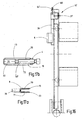
- the push rod 8 is in FIG. 6 separately illustrated. It is formed by a straight rod, which is preferably a rectangular profile ( FIG. 6 b) having.
- the opposite flat sides of the push rod 8 are connected to the back 49 along edges 47, 48 having the shape of chamfers.
- the upper end surface 63 of the push rod 8 is connected via a chamfer with the back 49.
- the insertion of the push rod 8 in the side support 4 in particular in the passage 26, 27 is facilitated by these bevels 47, 48, and by the chamfers 44, 45 of the connecting pieces 24, 25.
- the rear side 49 of the push rod 8 bears against the inside of the web 21 of the side support 4.
- the push rod 8 is bounded at one end by the back and at the other end by a narrow side 65.
- the push rod 8 has a constant cross section over its entire length.
- it may be provided with a connecting element 28 ( Figure 6a, 6c ), to which a separate linear guide 29 can be assigned ( FIG. 3 ).
- On the connecting element 28 can connect via a suitable joint connection of the connecting rod 12.
- the clamping device 16 is arranged ( Figure 7a ).
- the clamping device 16 has a cuboidal insert 50 preferably made of a metallic material. This insert 50 is between the two legs 19, 20 of the side support 4 with a known fastening means 46 (FIG. FIG. 5 ) held firmly.
- the insert 50 may preferably have a threaded bore 51 for receiving a tensioning means 30.
- the clamping means 30 may be formed in the form of a screw.
- the clamping device 16 also includes a wedge piece 54, which is movably held between the two legs 19, 20 of the side support 4. In this case, the two flat sides of the wedge piece 54 may be in contact with the side surfaces 19, 20.
- the wedge piece 54 has a wedge-shaped end 57 on its end surface facing away from the clamping means 30. In the relaxed state, this wedge-shaped end can rest against a complementary abutment surface 58 of the connection piece 24 or stand at a small distance therefrom.
- the wedge piece 54 is through a Spring element 55, which on the end faces of the bent legs 19, 20, the edges 22, 23 held slidably.
- the spring element 55 may be formed in the form of a leaf spring and is connected by a holding means 56 with the wedge piece 54.
- the first narrow side 59 of the wedge piece 54 project beyond the opening of the U-shaped side support 4, it can also be flush with this.
- the second narrow side 61 of the wedge piece 54 is oriented in the direction of the narrow side 65 of the push rod 8 out. If the clamping means 30 is adjusted, so that the in Figure 7a and 7b decreases the specified distance Y, the wedge piece 54 moves due to the interaction of its wedge-shaped end 57 with the contact surface 58 of the fitting 24 which is fixedly connected to the shaft rod 2, transverse to the longitudinal direction of the side support 4 on the push rod 8.
- the clamping means 30 can be adjusted so far that the push rod 8 between the second narrow side 61 of the wedge piece 54 and the web 21 of the side support 4 is firmly clamped ( FIG. 7b ). As a result, the drive of the heald 1 is ensured via the push rod 8 and the side support 4.
- FIG. 8a and FIG. 8b show another embodiment of the clamping device 16. Except for the second narrow side 61 of the clamping piece 54 and this opposite narrow side 65 of the push rod 8 are the clamping devices according to the FIGS. 7 and 8th identical. The description applies by reference to the same reference numerals.
- the second narrow side 61 of the clamping piece 54 and the opposite narrow side 65 of the push rod 8 form-fitting means, for example in the form of a toothing 35 , This makes a particularly strong, stable connection possible.
- FIG. 8a shows the clamping device 16 in the relaxed state while FIG. 8b the clamping device 16 in the clamped state shows.
- FIG. 9a and FIG. 9b show another embodiment of the clamping device 16. Except for the second narrow side 61 of the clamping piece 54 and this opposite narrow side 65 of the push rod 8, the clamping devices according to FIG. 7 and 9 identical. The description applies by reference to the same reference numerals.
- the second narrow side 61 of the clamping piece 54 is arranged at an acute angle ⁇ to the back of the side support 4.
- the narrow side 65 of the push rod 8 is arranged complementary to the narrow side 61. If the distance y is reduced by the adjustment of the tensioning means 30, a clamping device 16 acts according to FIG FIG. 9 in that the push rod 8 frictionally rests up against an adjusting means 60.
- FIG. 9a shows the clamping device 16 in the relaxed state while FIG. 9b the clamping device 16 in the clamped state shows.
- the clamping device 16 may have, in addition to the clamping means 30, a stop means or adjusting means, for example in the form of an adjusting means 60.
- the adjusting means 60 may be designed in the form of a screw and is held adjustably in the longitudinal direction of the push rod 8.
- the insert 50 may have a second threaded bore 52, which receives the adjusting means 60.
- a known device such as a hexagon socket can be used at one end.
- the adjusting means 60 has a contact surface 62. This system 62 cooperates with the end face 63 of the push rod 8.
- a holding means 64 can be found, for example in the form of a lock nut application.
- FIG. 10 shows another embodiment of the clamping device 16.
- the insert 50 'of the clamping device 16 has a simplified adjusting or adjusting means 60 in the form of a stop surface 66. This adjustment is held stationary.
- the stop surface 66 is opposite the end face 63 of the push rod 8.
- the side support 4 has a recess 68 in the end region. In this recess 68, a spacing means 67 can engage to set the position of the heald 1 with respect to the push rod 8. This allows the setting of multiple healds 1 a loom in a quick easy way. To set different heights of multiple healds 1 spacers 67 can be used with different heights application. Otherwise applies to the embodiment according to FIG. 10 at the same reference numerals, the description accordingly.
- the adjusting means 60 is formed on the push rod 8. Then the adjusting means is not part of the clamping device 16.
- the adjusting means is, for example, in the form of a projection 75 at the lower end of Push rod 8 like FIG. 6c shows trained.
- the projection 75 may be in the form of a pin which fits tightly into a corresponding bore in the push rod 8.
- the projection 75 may also be seamless, integrally formed on the push rod 8.
- An adjusting means designed in this way prevents the side support 4 from falling down over the push rod 8 of the heald 1 when the heald 1 is inserted. Thus, it is also avoided that in the connection of the heald shaft 1 with the drive device of the weaving machine of the heald 1 comes into contact with the connecting element 28.
- the clamping means 30 is released and the side support 4 with respect to the push rod 8 moved up or down.
- the displacement can be effected by means of the adjusting means 60.
- the clamping device 30 is tightened again.
- the clamping device 17 in the essential features of the clamping device 16 corresponds.
- the clamping means 30 of the clamping device 16 and the clamping means of the clamping device 17 are released. Then, the heald 1 can be deducted from the push rod 8 (and 9) upwards, as it FIG. 11 shows. Thereafter, the same heald 1 or another heald 1 on the push rod 8 (and 9) pushed back and locked in the desired height.
- no further parts are to be released or displaced beyond the opening of the tensioning means 30, neither in the longitudinal direction of the side support 4 5 still in the longitudinal direction of a shaft rod 2, 3.
- the guides 6, 7, 29 may be held stationary. Nevertheless, the heald 1 can be replaced.
- a tightening of the clamping device 16 at the same time means a tightening of the clamping device 17.
- a release of the clamping device 16 means at the same time a release of the clamping device 17th
- FIG. 11 illustrates the heddle 1 when it is separated from the push rod 8. He can now on the Push rod 8 are put back by his side support 4 is pushed over the push rod 8. It can then be locked in a desired working height, as has been described above. As can be seen, the height adjustment of the heald 1 and the same does not require access to the space below the heald 1.
- the handling of the shaft connection device 18 according to the invention is therefore particularly comfortable.
- FIG. 12 It illustrates a modified embodiment of the heald 1. It differs from the above described heald shaft 1 by the elimination of the connecting element 28, the linear guide 29 and the connecting rod 12.
- the push rod 8 is directly connected to the angle lever 14.
- the push rod 8 has a certain flexibility or resilient compliance, by which it can spring in the direction of the shaft rod 3 and the web 21 of the side support 4.
- the push rod 8 at its lower pivot point 31 of the pivotal movement of the angle lever 14 follow pendulum. This in particular when the push rod 8 in the side support 4 can perform a pivoting movement. It is then the entire length of the clamping device 16 to the pivot point 31 for flexible deflection and pivoting of the push rod 8 available.
- the lower passage 27 is measured perpendicular to the web 21, further than the width of the push rod 8 measured in the same direction.
- the width of the passage 26 (FIG. FIG. 5 ) is preferably larger than the width of the push rod 8 to be measured in the same direction.
- FIGS. 13 to 17 Another embodiment of the invention is in the FIGS. 13 to 17 illustrated.
- the peculiarity of this embodiment is that both the side support 4 ( FIG. 15 ) as well as the push rod 8 ( FIG. 14 ) are formed as U-profiles.
- the push rod 8 overlaps with their legs 70, 71, the legs 19, 20 of the side support 4.
- the side support 4 is disposed within the push rod 8, as in particular Figure 17a evident.
- the push rod 8 is how FIG. 14 shows, provided at its upper end with a solid profile bar 39 which extends beyond its upper end.
- the solid profile bar 39 is for example. Welded to the push rod 8 and forms the upper end thereof.
- the side support 4 is provided at its upper end with a U-shaped clamping collar 40. This projects beyond the back or web 21 of the side support 4 and its two legs 72, 73 are connected to the legs 19, 20 of the side support 4. Between them, a solid insert 50 'is fixedly arranged, in which the clamping means 30', held movable in the transverse direction to the central axis of the push rod 8, in a threaded bore 51 'sits.
- FIG. 16 and FIG. 17b shows the solid profile bar 39 are clamped in the clamping sleeve 40 when the clamping means 30 'is tightened.
- the solid profile bar 39 can also, as FIG. 16 shows, with the sliding guide 6 are engaged.
- the clamping device 16 ' may in addition to the clamping means 30 'have an adjusting means 60'.
- the adjusting means 60 ' may be formed in the form of a screw and is held adjustable in the longitudinal direction of the push rod 8.
- the insert 50 ' may have a projection 74, which protrudes beyond the side support 4, and a second threaded bore 52', which receives the adjustment means 60 '.
- For adjustment of the adjustment 60 ' can find at one end a known device, such as a hexagon socket, application. At the adjustment of the adjusting means 60 'opposite the other end, this has a contact surface 62' on. This system 62 'cooperates with the end face 63' of the push rod 8.
- a holding means 64 ' for example in the form of a lock nut 64' find application.
- the shaft connection device 18 has a push rod 8 and a side support 4 which fit into one another with little transverse play.
- the shaft connecting device 18 includes a clamping device 16 with a stop means 60, 60 ', 66 and a clamping means 30, 30' which connect the side support 4 and the push rod 8 exclusively at their respective upper end.
- the opening, closing and adjustment of the connection between the push rod 8 and the side support 4 is particularly simple and comfortable.
- the side support 4 and the push rod 8 support each other from each other, resulting in a high dynamic load capacity. Overall, the configuration is simple, clear and cost-effective.
Landscapes
- Engineering & Computer Science (AREA)
- Textile Engineering (AREA)
- Looms (AREA)
Claims (24)
- Dispositif d'accouplement (18) pour un cadre à lisses (1) d'un métier mécanique, qui comprend :- un soutien latéral (4), qui en service est disposé verticalement et qui relie une lamette supérieure (2) et une lamette inférieure (3),- une jambe de force (8) qui présente une extrémité supérieure libre, qui est appliquée sur le soutien latéral et qui, en service, a son extrémité inférieure reliée à un entraînement se déplaçant en va et vient,- un moyen de réglage (60, 60', 66) qui est associé au soutien latéral (4) sur lequel il est monté et qui détermine la hauteur du cadre à lisses (1) par rapport à la jambe de force (8),ce dispositif étant caractérisé en ce que la jambe de force (8) présente à une extrémité une face frontale (63, 63') qui, lors du réglage de la hauteur du cadre à lisses (1), coopère avec le moyen de réglage (60,60', 66).
- Dispositif d'accouplement selon la revendication 1, caractérisé en ce que le moyen de réglage (60, 60', 66) est en contact direct avec la jambe de force (8).
- Dispositif d'accouplement selon la revendication 1, caractérisé en ce que le moyen de réglage (60, 60', 66) est disposé à l'extrémité supérieure de la jambe de force (4), afin de pouvoir régler la hauteur du cadre à lisses (1) par rapport à la jambe de force (8).
- Dispositif d'accouplement selon la revendication 1 ou 2, caractérisé en ce que le moyen de réglage (60, 60') est mobile.
- Dispositif d'accouplement selon la revendication 1 ou 2, caractérisé en ce que la jambe de force (8) présente à une extrémité une face frontale (63, 63') qui, lors du réglage de la hauteur du cadre à lisses (1) est en contact avec le moyen de réglage (60, 60').
- Dispositif d'accouplement selon la revendication 1 ou 2, comprenant un dispositif de serrage (16, 16') disposé à l'extrémité supérieure du soutien latéral (4) afin de bloquer celui-ci sur l'extrémité supérieure libre de la jambe de force (8).
- Dispositif d'accouplement selon la revendication 5, caractérisé en ce que le dispositif de serrage (16, 16') est disposé au-dessus de la lamette supérieure (2).
- Dispositif d'accouplement selon la revendication 5, caractérisé en ce que le dispositif de serrage (16, 16') est disposé au-dessus de la jambe de force (8).
- Dispositif d'accouplement selon la revendication 1, caractérisé en ce que le soutien latéral (4) et la jambe de force (8) sont en prise par enveloppement l'un dans l'autre.
- Dispositif d'accouplement selon la revendication 1, caractérisé en ce que le soutien latéral (4) est un profilé en U dont le côté ouvert est en regard des lamettes (2, 3).
- Dispositif d'accouplement selon la revendication 1, caractérisé en ce que la jambe de force (8) passe à l'intérieur de l'appui latéral (4).
- Dispositif d'accouplement selon la revendication 1, caractérisé en ce que la jambe de force (8) est un profilé plein à section rectangulaire.
- Dispositif d'accouplement selon la revendication 1, caractérisé en ce que le soutien latéral (4) est en prise avec un dispositif de guidage par glissement (6).
- Dispositif d'accouplement selon la revendication 1, caractérisé en ce que la jambe de force (8) est un profilé en U qui enveloppe le soutien latéral (4).
- Dispositif d'accouplement selon la revendication 1, caractérisé en ce que le soutien latéral (4) est un profilé en U.
- Dispositif d'accouplement selon la revendication 1, caractérisé en ce que l'extrémité supérieure de la jambe de force (8) est un profilé plein (39).
- Dispositif d'accouplement selon la revendication 1, caractérisé en ce que la jambe de force (8) est en prise avec un dispositif de guidage par glissement (6).
- Dispositif d'accouplement selon la revendication 16, caractérisé en ce que le profilé plein (39) est en prise avec un dispositif de guidage par glissement (6).
- Dispositif d'accouplement selon la revendication 6, caractérisé en ce que le dispositif de serrage (16, 17) est conçu de manière à mettre l'appui latéral (4, 5) et la jambe de force (8, 9) en tension l'un contre l'autre.
- Dispositif d'accouplement selon la revendication 1, caractérisé en ce que l'appui latéral (4) et la jambe de force (8) présentent des dentures respectives (35) par lesquelles ils sont en prise.
- Dispositif d'accouplement selon la revendication 6, caractérisé en ce que le dispositif de serrage (16, 17) est un dispositif de serrage à coin.
- Dispositif d'accouplement selon la revendication 21, caractérisé en ce que le dispositif de serrage à coin comprend une pièce de coin (54) qui, par un moyen de tension (30) peut être déplacée par rapport à la jambe de force (8) et venir s'appliquer sur une portée d'appui (58) disposée obliquement par rapport à la jambe de force.
- Procédé pour séparer un cadre à lisses (1) d'un dispositif d'entraînement d'un métier mécanique équipé d'un dispositif d'accouplement (18) de ce cadre, selon la revendication 5, caractérisé en ce que pour séparer le cadre à lisses (1) du dispositif d'entraînement du métier, l'accès s'effectue exclusivement par le dessus de la lamette supérieure (2).
- Procédé pour séparer un cadre à lisses (1) d'un dispositif d'entraînement d'un métier mécanique équipé d'un dispositif d'accouplement (18) de ce cadre selon la revendication 23, caractérisé en ce que pour effectuer cette séparation, il n'y a à libérer ou faire coulisser aucune partie autre que le dispositif de serrage (16, 16').
Priority Applications (4)
| Application Number | Priority Date | Filing Date | Title |
|---|---|---|---|
| EP07012444A EP2009157B1 (fr) | 2007-06-26 | 2007-06-26 | Dispositif d'accouplement pour un cadre à lisses |
| CN200810130637.7A CN101333720B (zh) | 2007-06-26 | 2008-06-25 | 用于综框的轴连接设备 |
| JP2008166998A JP2009007734A (ja) | 2007-06-26 | 2008-06-26 | 綜絖軸のための軸連結デバイス |
| US12/147,101 US7784499B2 (en) | 2007-06-26 | 2008-06-26 | Shaft connecting device for a heald shaft |
Applications Claiming Priority (1)
| Application Number | Priority Date | Filing Date | Title |
|---|---|---|---|
| EP07012444A EP2009157B1 (fr) | 2007-06-26 | 2007-06-26 | Dispositif d'accouplement pour un cadre à lisses |
Publications (2)
| Publication Number | Publication Date |
|---|---|
| EP2009157A1 EP2009157A1 (fr) | 2008-12-31 |
| EP2009157B1 true EP2009157B1 (fr) | 2010-01-06 |
Family
ID=38688435
Family Applications (1)
| Application Number | Title | Priority Date | Filing Date |
|---|---|---|---|
| EP07012444A Expired - Fee Related EP2009157B1 (fr) | 2007-06-26 | 2007-06-26 | Dispositif d'accouplement pour un cadre à lisses |
Country Status (4)
| Country | Link |
|---|---|
| US (1) | US7784499B2 (fr) |
| EP (1) | EP2009157B1 (fr) |
| JP (1) | JP2009007734A (fr) |
| CN (1) | CN101333720B (fr) |
Families Citing this family (9)
| Publication number | Priority date | Publication date | Assignee | Title |
|---|---|---|---|---|
| JP2009293154A (ja) * | 2008-06-05 | 2009-12-17 | Tsudakoma Corp | 綜絖枠高さ調節装置 |
| CN102330239A (zh) * | 2011-07-21 | 2012-01-25 | 吴江市锦邦纺织品有限公司 | 带高度调节装置的织布机综框 |
| EP2573240B1 (fr) * | 2011-09-20 | 2015-05-27 | Groz-Beckert KG | Corde à lisse de sécurité à vitesse élevée |
| EP2586895B1 (fr) * | 2011-10-31 | 2018-12-19 | Groz-Beckert KG | Dispositif de raccordement pour la liaison d'une corde à lisse et d'un entraînement d'arbre |
| CN102704139A (zh) * | 2012-05-21 | 2012-10-03 | 广东丰凯机械股份有限公司 | 一种织机的开口连杆与综框连接结构 |
| CN103014985A (zh) * | 2012-12-31 | 2013-04-03 | 徐钒丽 | 喷水织机的开口机构 |
| CN104328564B (zh) * | 2014-10-22 | 2016-03-02 | 杭州创兴云智能设备科技股份有限公司 | 一种织口高度可调的双层织物纺织机 |
| ITUB20155435A1 (it) * | 2015-11-10 | 2016-02-10 | Itema Spa | Sistema di aggancio rapido dei quadri-licci in un telaio di tessitura |
| US10979728B2 (en) * | 2017-04-24 | 2021-04-13 | Intel Corporation | Intelligent video frame grouping based on predicted performance |
Family Cites Families (17)
| Publication number | Priority date | Publication date | Assignee | Title |
|---|---|---|---|---|
| AT348959B (de) * | 1975-12-24 | 1979-03-12 | Sulzer Ag | Vorrichtung zum kuppeln eines webschaftes mit einer auf- und abwaerts bewegbaren antriebsplatine |
| CH681635A5 (fr) * | 1989-07-07 | 1993-04-30 | Sulzer Ag | |
| CH681374A5 (fr) * | 1989-07-07 | 1993-03-15 | Sulzer Ag | |
| JPH0638124Y2 (ja) | 1989-08-29 | 1994-10-05 | 津田駒工業株式会社 | ラテラルガイド案内装置 |
| DE3933616C2 (de) * | 1989-10-07 | 1998-07-02 | Dornier Gmbh Lindauer | Webmaschine für standstellenempfindliche Gewebe, insbesondere Köpergewebe |
| JPH0721580Y2 (ja) | 1990-03-16 | 1995-05-17 | 株式会社豊田自動織機製作所 | 織機の経糸開口装置における綜絖枠吊下げ装置 |
| BE1004960A3 (nl) | 1991-06-26 | 1993-03-02 | Picanol Nv | Inrichting voor het vormen van een gaap bij weefmachines. |
| DE4343882C1 (de) * | 1993-12-22 | 1995-01-19 | Dornier Gmbh Lindauer | Webschaftkupplung und Vorrichtung zum simultanen Öffnen und Schließen einer Vielzahl von Webschaftkupplungen in einer Webmaschine |
| JPH0921030A (ja) | 1995-07-03 | 1997-01-21 | Toyota Autom Loom Works Ltd | 織機における開口装置 |
| DE19548848C1 (de) * | 1995-12-27 | 1996-09-12 | Dornier Gmbh Lindauer | Webschaftkupplung mit einer Entkupplungsvorrichtung |
| JPH10130983A (ja) * | 1996-10-30 | 1998-05-19 | Toyota Autom Loom Works Ltd | 織機における開口装置 |
| FR2815048B1 (fr) | 2000-10-06 | 2002-12-20 | Staubli Sa Ets | Dispositif pour l'accouplement d'un cadre de lisses sur un element de transmission de mouvement, ensemble d'entrainement et metier a tisser equipe d'un tel ensemble |
| DE10111017B4 (de) * | 2001-03-07 | 2006-02-02 | Lindauer Dornier Gmbh | Antrieb für die Webschäfte einer Webmaschine |
| DE10349381B4 (de) * | 2003-10-21 | 2005-08-25 | Groz-Beckert Kg | Webschaft mit neuartigem Eckverbinder |
| DE102004047929B3 (de) * | 2004-10-01 | 2005-12-01 | Groz-Beckert Kg | Verbesserter Webschaft |
| US7475708B2 (en) * | 2004-11-17 | 2009-01-13 | Groz-Beckert Kg | Shaft drive for heald shafts of weaving machines |
| DE102005029701B3 (de) * | 2005-06-24 | 2006-06-14 | Groz-Beckert Kg | Webschaft mit Selbstspannverschluss |
-
2007
- 2007-06-26 EP EP07012444A patent/EP2009157B1/fr not_active Expired - Fee Related
-
2008
- 2008-06-25 CN CN200810130637.7A patent/CN101333720B/zh not_active Expired - Fee Related
- 2008-06-26 JP JP2008166998A patent/JP2009007734A/ja active Pending
- 2008-06-26 US US12/147,101 patent/US7784499B2/en not_active Expired - Fee Related
Also Published As
| Publication number | Publication date |
|---|---|
| CN101333720B (zh) | 2013-01-02 |
| EP2009157A1 (fr) | 2008-12-31 |
| US7784499B2 (en) | 2010-08-31 |
| US20090000687A1 (en) | 2009-01-01 |
| CN101333720A (zh) | 2008-12-31 |
| JP2009007734A (ja) | 2009-01-15 |
Similar Documents
| Publication | Publication Date | Title |
|---|---|---|
| EP2009157B1 (fr) | Dispositif d'accouplement pour un cadre à lisses | |
| EP1893365B1 (fr) | Dispositif de fixation d'outil pour dispositif d'entraînement par came | |
| EP0627507B1 (fr) | Machine de cardage avec chapeaux mobiles | |
| EP0675292A1 (fr) | Structure avec au moins deux barres profilées creuses mutuellement perpendiculaires | |
| EP0740766A1 (fr) | Ensemble de plaques a grilles | |
| DE102012218762A1 (de) | Vorrichtung zur sicherung von ladegut | |
| EP1103498A1 (fr) | Dispositif pour saisir des charges, qui en particulier sont saisi par le haut ou latéralement au moyen d' un manipulateur | |
| AT515130A1 (de) | Biegepresse | |
| EP1526198A2 (fr) | Cadre à lisses avec nouveau joint d'angle | |
| EP0539687A1 (fr) | Joint perpendiculaire pour des profilés avec des rainures longitudinales | |
| EP1736580B1 (fr) | Cadre à lisses avec serrure de serrage | |
| WO2010105591A2 (fr) | Dispositif pour estamper, couper et plier des tôles à l'équerre | |
| DE1752346C3 (de) | Bombiervorrichtung für eine Abkantpresse | |
| DE2325148C3 (de) | Vorrichtung zum Zusammenbau von Profilen für Metallstrukturen | |
| DE10223894B4 (de) | Plattenklemmvorrichtung | |
| DE2402054C2 (de) | Vorrichtung zum Festspannen von Werkstücken auf einer Aufspannplatte | |
| DE102005019511A1 (de) | Einrichtung zum automatischen Stapelwechsel | |
| EP1736579B1 (fr) | Cadre à lisses | |
| EP1245861B1 (fr) | Dispositif pour enfoncer des agrafes de jonction de courroie | |
| DE19955289C2 (de) | Buchsenziehvorrichtung | |
| DE1552612B2 (de) | Schneidemaschine fuer stabmaterial | |
| DE8134202U1 (de) | Sortiervorrichtung | |
| AT412497B (de) | Verbinder für profilstäbe | |
| DE4233233C2 (de) | Handhebelpresse | |
| DE60319461T2 (de) | Werkzeugkupplungsvorrichtung, insbesondere für Pressen |
Legal Events
| Date | Code | Title | Description |
|---|---|---|---|
| PUAI | Public reference made under article 153(3) epc to a published international application that has entered the european phase |
Free format text: ORIGINAL CODE: 0009012 |
|
| AK | Designated contracting states |
Kind code of ref document: A1 Designated state(s): AT BE BG CH CY CZ DE DK EE ES FI FR GB GR HU IE IS IT LI LT LU LV MC MT NL PL PT RO SE SI SK TR |
|
| AX | Request for extension of the european patent |
Extension state: AL BA HR MK RS |
|
| 17P | Request for examination filed |
Effective date: 20090122 |
|
| GRAP | Despatch of communication of intention to grant a patent |
Free format text: ORIGINAL CODE: EPIDOSNIGR1 |
|
| AKX | Designation fees paid |
Designated state(s): DE FR |
|
| RBV | Designated contracting states (corrected) |
Designated state(s): BE FR |
|
| GRAS | Grant fee paid |
Free format text: ORIGINAL CODE: EPIDOSNIGR3 |
|
| REG | Reference to a national code |
Ref country code: DE Ref legal event code: 8566 |
|
| GRAA | (expected) grant |
Free format text: ORIGINAL CODE: 0009210 |
|
| AK | Designated contracting states |
Kind code of ref document: B1 Designated state(s): BE FR |
|
| PLBE | No opposition filed within time limit |
Free format text: ORIGINAL CODE: 0009261 |
|
| STAA | Information on the status of an ep patent application or granted ep patent |
Free format text: STATUS: NO OPPOSITION FILED WITHIN TIME LIMIT |
|
| 26N | No opposition filed |
Effective date: 20101007 |
|
| PGFP | Annual fee paid to national office [announced via postgrant information from national office to epo] |
Ref country code: BE Payment date: 20140620 Year of fee payment: 8 |
|
| PGFP | Annual fee paid to national office [announced via postgrant information from national office to epo] |
Ref country code: FR Payment date: 20140619 Year of fee payment: 8 |
|
| REG | Reference to a national code |
Ref country code: FR Ref legal event code: ST Effective date: 20160229 |
|
| PG25 | Lapsed in a contracting state [announced via postgrant information from national office to epo] |
Ref country code: FR Free format text: LAPSE BECAUSE OF NON-PAYMENT OF DUE FEES Effective date: 20150630 |
|
| PG25 | Lapsed in a contracting state [announced via postgrant information from national office to epo] |
Ref country code: BE Free format text: LAPSE BECAUSE OF NON-PAYMENT OF DUE FEES Effective date: 20150630 |