EP2006949A2 - Verfahren zum herstellen einer fotoelektrode für eine farbstoffsensibilisierte solarzelle, fotoelektrode für eine farbstoffsensibilisierte solarzelle und farbstoffsensibilisierte solarzelle - Google Patents
Verfahren zum herstellen einer fotoelektrode für eine farbstoffsensibilisierte solarzelle, fotoelektrode für eine farbstoffsensibilisierte solarzelle und farbstoffsensibilisierte solarzelle Download PDFInfo
- Publication number
- EP2006949A2 EP2006949A2 EP07737690A EP07737690A EP2006949A2 EP 2006949 A2 EP2006949 A2 EP 2006949A2 EP 07737690 A EP07737690 A EP 07737690A EP 07737690 A EP07737690 A EP 07737690A EP 2006949 A2 EP2006949 A2 EP 2006949A2
- Authority
- EP
- European Patent Office
- Prior art keywords
- dye
- solar cell
- sensitized solar
- layer
- photoelectrode
- Prior art date
- Legal status (The legal status is an assumption and is not a legal conclusion. Google has not performed a legal analysis and makes no representation as to the accuracy of the status listed.)
- Withdrawn
Links
Images

Classifications
-
- H—ELECTRICITY
- H01—ELECTRIC ELEMENTS
- H01G—CAPACITORS; CAPACITORS, RECTIFIERS, DETECTORS, SWITCHING DEVICES OR LIGHT-SENSITIVE DEVICES, OF THE ELECTROLYTIC TYPE
- H01G9/00—Electrolytic capacitors, rectifiers, detectors, switching devices, light-sensitive or temperature-sensitive devices; Processes of their manufacture
- H01G9/20—Light-sensitive devices
- H01G9/2027—Light-sensitive devices comprising an oxide semiconductor electrode
- H01G9/2031—Light-sensitive devices comprising an oxide semiconductor electrode comprising titanium oxide, e.g. TiO2
-
- H—ELECTRICITY
- H01—ELECTRIC ELEMENTS
- H01G—CAPACITORS; CAPACITORS, RECTIFIERS, DETECTORS, SWITCHING DEVICES OR LIGHT-SENSITIVE DEVICES, OF THE ELECTROLYTIC TYPE
- H01G9/00—Electrolytic capacitors, rectifiers, detectors, switching devices, light-sensitive or temperature-sensitive devices; Processes of their manufacture
- H01G9/20—Light-sensitive devices
- H01G9/2004—Light-sensitive devices characterised by the electrolyte, e.g. comprising an organic electrolyte
- H01G9/2013—Light-sensitive devices characterised by the electrolyte, e.g. comprising an organic electrolyte the electrolyte comprising ionic liquids, e.g. alkyl imidazolium iodide
-
- H—ELECTRICITY
- H01—ELECTRIC ELEMENTS
- H01G—CAPACITORS; CAPACITORS, RECTIFIERS, DETECTORS, SWITCHING DEVICES OR LIGHT-SENSITIVE DEVICES, OF THE ELECTROLYTIC TYPE
- H01G9/00—Electrolytic capacitors, rectifiers, detectors, switching devices, light-sensitive or temperature-sensitive devices; Processes of their manufacture
- H01G9/20—Light-sensitive devices
- H01G9/2059—Light-sensitive devices comprising an organic dye as the active light absorbing material, e.g. adsorbed on an electrode or dissolved in solution
-
- Y—GENERAL TAGGING OF NEW TECHNOLOGICAL DEVELOPMENTS; GENERAL TAGGING OF CROSS-SECTIONAL TECHNOLOGIES SPANNING OVER SEVERAL SECTIONS OF THE IPC; TECHNICAL SUBJECTS COVERED BY FORMER USPC CROSS-REFERENCE ART COLLECTIONS [XRACs] AND DIGESTS
- Y02—TECHNOLOGIES OR APPLICATIONS FOR MITIGATION OR ADAPTATION AGAINST CLIMATE CHANGE
- Y02E—REDUCTION OF GREENHOUSE GAS [GHG] EMISSIONS, RELATED TO ENERGY GENERATION, TRANSMISSION OR DISTRIBUTION
- Y02E10/00—Energy generation through renewable energy sources
- Y02E10/50—Photovoltaic [PV] energy
- Y02E10/542—Dye sensitized solar cells
-
- Y—GENERAL TAGGING OF NEW TECHNOLOGICAL DEVELOPMENTS; GENERAL TAGGING OF CROSS-SECTIONAL TECHNOLOGIES SPANNING OVER SEVERAL SECTIONS OF THE IPC; TECHNICAL SUBJECTS COVERED BY FORMER USPC CROSS-REFERENCE ART COLLECTIONS [XRACs] AND DIGESTS
- Y02—TECHNOLOGIES OR APPLICATIONS FOR MITIGATION OR ADAPTATION AGAINST CLIMATE CHANGE
- Y02E—REDUCTION OF GREENHOUSE GAS [GHG] EMISSIONS, RELATED TO ENERGY GENERATION, TRANSMISSION OR DISTRIBUTION
- Y02E10/00—Energy generation through renewable energy sources
- Y02E10/50—Photovoltaic [PV] energy
- Y02E10/549—Organic PV cells
-
- Y—GENERAL TAGGING OF NEW TECHNOLOGICAL DEVELOPMENTS; GENERAL TAGGING OF CROSS-SECTIONAL TECHNOLOGIES SPANNING OVER SEVERAL SECTIONS OF THE IPC; TECHNICAL SUBJECTS COVERED BY FORMER USPC CROSS-REFERENCE ART COLLECTIONS [XRACs] AND DIGESTS
- Y02—TECHNOLOGIES OR APPLICATIONS FOR MITIGATION OR ADAPTATION AGAINST CLIMATE CHANGE
- Y02P—CLIMATE CHANGE MITIGATION TECHNOLOGIES IN THE PRODUCTION OR PROCESSING OF GOODS
- Y02P70/00—Climate change mitigation technologies in the production process for final industrial or consumer products
- Y02P70/50—Manufacturing or production processes characterised by the final manufactured product
Definitions
- the present invention relates to a production process of a photoelectrode for dye-sensitized solar cell, a photoelectrode for dye-sensitized solar cell and a dye-sensitized solar cell.
- this dye-sensitized solar cell has a photoelectrode composed of a transparent substrate with a transparent conductive layer formed on a transparent base and a photoelectric conversion layer formed on this transparent conductive layer by carrying a sensitizing dye on semiconductor particles such as titania particles, and a counter electrode electrically connected to this photoelectrode, and an electrolyte solution is interposed between these photoelectrode and counter electrode.
- This dye-sensitized solar cell has photoelectric conversion capability equal to or more than a silicon solar cell heretofore in use, and further has advantages that it can be mass-produced at low cost because it can be produced by a printing system or flow production system under atmospheric pressure, and an expensive equipment is unnecessary, in addition to less resource constraint than the conventional silicon solar cell with respect to titanium oxide and the sensitizing dye that are materials, the component of the electrolyte solution, etc.
- a materials of the transparent base of the transparent substrate conventionally used in the dye-sensitized solar cell may be mentioned glass.
- a pure oxide semiconductor film is generally formed by, for example, applying a paste composed of nano particles of titania containing an organic binder on to a conductive glass substrate and calcining the paste at a temperature of 400°C or higher, thereby burning the organic binder.
- the photoelectric conversion efficiency of such a dye-sensitized solar cell is about 8%, and about 11% on the maximum.
- the plastic substrate whose transparent base is a plastic plate or plastic film, as the transparent substrate, and an investigation has been carried out thereon.
- the reason is that weight saving and cost reduction can be made, and the resulting solar cell is expected to be, for example, placeable on a roof or applicable to a curved surface such as a car body, or used as a power source of a potable telephone because the plastic substrate has merits of being tough and flexible.
- the plastic substrate is low in heat resistance, and so the process generally used in the case of the glass substrate such as calcination at a temperature of 400°C or higher may not be applied to the plastic substrate as it is.
- a paste containing semiconductor particles and a binder is generally used (see, for example, Patent Arts. 1 to 3).
- This binder is used for the purpose of improving coating ability on the transparent substrate to make the adhesion between the transparent substrate and the semiconductor particles good and increasing the durability of the resulting dye-sensitized solar cell.
- the paste containing the binder is prepared by using a solvent for dissolving the binder.
- a solvent is often an organic solvent, and so there is a problem that the plastic material species used as the transparent base are limited.
- Patent Art. 2 discloses a dye-sensitized solar cell with a photoelectric conversion layer formed by applying a paste containing a binder, in which one kind of fine semiconductor particles, on which a sensitizing dye has been carried in advance, are dispersed, on to a conductive PET substrate (transparent substrate) and then subjecting the paste to a pressing treatment.
- a high pressure of about 1,000 MPa for the purpose of, for example, improving the adhesion between the conductive PET substrate and the fine semiconductor particles causes problems of breaking of a conductive film of the conductive PET substrate and distortion of the conductive PET substrate itself.
- the sensitizing dye on the surfaces of the fine semiconductor particles directly receiving a pressing pressure by the pressing treatment is separated, and contact between the fine semiconductor particles is prevented by the sensitizing dye to inhibit electron transfer.
- the resulting dye-sensitized solar cell becomes low in performance.
- the dye-sensitized solar cell produced by using the binder in such a manner has been proved to be low in photoelectric conversion efficiency. The reason for this is presumed to be attributable to the fact that the binder is entered into between the fine semiconductor particles and between the fine semiconductor particles and the transparent substrate to prevent the junction or contact thereof, thereby inhibiting electron transfer.
- Non-Patent Art. 1 Nature, 353, pp. 737-740, 1991
- the present invention has been made in view of the foregoing circumstances and has as its object the provision of a photoelectrode for dye-sensitized solar cell, by which a dye-sensitized solar cell capable of obtaining a high photoelectric conversion efficiency even when a plastic substrate is used as a transparent substrate, and retaining a high level of photoelectric conversion efficiency even when the quantity of incident light is changed can be surely obtained with good reproducibility, a production process thereof, and a dye-sensitized solar cell obtained by this photoelectrode for dye-sensitized solar cell.
- the present inventors have carried out an extensive investigation with a view toward achieving the above object.
- an aqueous paste containing semiconductor particles and water and containing neither a binder nor an organic solvent is used, and a coating film formed by applying this paste on to a transparent substrate and drying the paste is subjected to a pressing treatment, whereby a photoelectric conversion layer can be formed on the transparent substrate with high adhesion to provide a photoelectrode for dye-sensitized solar cell, from which a dye-sensitized solar cell exhibiting a high photoelectric conversion efficiency can be obtained, and this photoelectrode is particularly effective in the case where a plastic substrate is used as a transparent substrate, and thus the present invention has been completed.
- a production process of a photoelectrode for dye-sensitized solar cell is a production process of a photoelectrode for dye-sensitized solar cell, which comprises forming a transparent conductive layer on a transparent base to provide a transparent substrate and laminating a photoelectric conversion layer on the transparent conductive layer of the transparent substrate, wherein the photoelectric conversion layer contains at least two kinds of semiconductor particles different in average particle diameter from each other and a sensitizing dye, and the process comprises a step of subjecting a coating film formed on the transparent conductive layer with an aqueous paste containing neither a binder nor an organic solvent and containing said at least two kinds of semiconductor particles different in average particle diameter to a pressing treatment.
- the surface of the transparent conductive layer of the transparent substrate may preferably be subjected to an ultrasonic cleaning treatment, an etching treatment and/or an UV-ozone treatment.
- the photoelectric conversion layer may be obtained by subjecting the coating film of the aqueous paste to the pressing treatment to provide a functional semiconductor layer and carrying the sensitizing dye on the functional semiconductor layer.
- the pressing treatment may preferably be conducted under conditions that the light transmittance of the functional semiconductor layer at a wavelength of 400 to 800 nm reaches 110 to 130% of a value before the pressing treatment.
- the photoelectric conversion layer may be obtained by forming one or more coating layers of an aqueous paste containing neither a binder nor an organic solvent and containing at least two kinds of semiconductor particles different in average particle diameter from each other on the layer obtained by subjecting the coating film of the aqueous paste to the dressing treatment to provide a functional semiconductor layer and carrying the sensitizing dye on the functional semiconductor layer.
- the pressing treatment may preferably be conducted under conditions that the light transmittance of the layer obtained by subjecting the coating film of the aqueous paste to the pressing treatment at a wavelength of 400 to 800 nm reaches 110 to 130% of a value before the pressing treatment.
- the functional semiconductor layer obtained through the step of subjecting the coating film of the aqueous paste to the pressing treatment may preferably be subjected to an UV-ozone treatment before carrying the sensitizing dye.
- the photoelectric conversion layer may be composed of a sensitizing dye-carried and pressed semiconductor layer obtained by carrying the sensitizing dye on the coating film of the aqueous paste and then conducting the pressing treatment.
- the pressing treatment may preferably be conducted under conditions that the light transmittance of the sensitizing dye-carried and pressed semiconductor layer at a wavelength of 400 to 800 nm reaches 110 to 130% of a value before the pressing treatment.
- the semiconductor particles may preferably be anatase crystal type titania particles.
- the semiconductor particles may preferably be obtained by a basic process.
- the basic process may preferably comprise a step of hydrolyzing a semiconductor metal alkoxide with a quaternary ammonium salt.
- the content of said at least two kinds of semiconductor particles different in average particle diameter in the aqueous paste may preferably be 5 to 30% by mass.
- the semiconductor particles contained in the aqueous paste may be two kinds of particles having an average particle diameter of 3 to 40 nm and an average particle diameter of 50 nm or greater.
- the pressing treatment may preferably be conducted at room temperature, and the pressing treatment may preferably be conducted under a pressure of from 5 MPa or higher to 500 MPa or lower.
- the transparent base of the transparent substrate may be a plastic transparent base.
- a transparent conductive layer composed of indium-tin composite oxide (ITO) may preferably be formed on the plastic transparent base by a sputtering method while conducting a heat treatment at a temperature lower than the heat-resistant temperature of the transparent base.
- ITO indium-tin composite oxide
- a photoelectrode for dye-sensitized solar cell is a photoelectrode for dye-sensitized solar cell, which is obtained by forming a transparent conductive layer on a transparent base to provide a transparent substrate, providing a functional semiconductor layer on the transparent conductive layer of the transparent substrate, and carrying a sensitizing dye on the functional semiconductor layer of the thus-obtained photoelectrode structure, wherein the functional semiconductor layer has a pressed layer in a state contacted with the transparent conductive layer, and the pressed layer contains at least two kinds of semiconductor particles different in average particle diameter from each other and contains no binder.
- said at least two kinds of semiconductor particles may preferably be two kinds of semiconductor particles having an average particle diameter of 3 to 40 nm and an average particle diameter of 50 nm or greater.
- the content of the semiconductor particles having the average particle diameter of 3 to 40 nm in said at least two kinds of semiconductor particles different in average particle diameter may preferably be 50 to 95% by mass.
- the functional semiconductor layer of the photoelectrode structure may be of a multilayer structure of the pressed layer and at least one layer laminated on the pressed layer, containing at least two kinds of semiconductor particles different in average particle diameter from each other, containing no binder and subjected to no pressing treatment.
- the thickness of the pressed layer of the functional semiconductor layer may preferably be 3 to 40 ⁇ m.
- the pressed layer of the functional semiconductor layer may bear traces of cracks filled.
- the light transmittances of a laminate of the transparent substrate and the pressed layer of the functional semiconductor layer in the photoelectrode structure at a wavelength of 500 nm and at a wavelength of 700 nm may preferably be 20 to 65% and 30 to 75%, respectively.
- a dye-sensitized solar cell comprises the above-described photoelectrode for dye-sensitized solar cell, wherein the photoelectrode for dye-sensitized solar cell is provided so as to oppose to a counter electrode through an electrolyte part.
- the photoelectrode for dye-sensitized solar cell of the present invention at least two kinds of specific semiconductor particles different in average particle diameter are caused to be contained in the photoelectric conversion layer, so that a high light absorption efficiency by the so-called light confinement effect can be achieved as to the sensitizing dye contained in the photoelectric conversion layer.
- this photoelectric conversion layer is formed by using the specific aqueous paste by means of the specific process that the coating film thereof is subjected to the pressing treatment, the semiconductor particles are closely bonded to one another by the pressing treatment, and when the transparent substrate is a plastic substrate, the semiconductor particles are caused to closely adhere to the transparent conductive layer of the transparent substrate by the flexibility thereof so as to cut into the surface of the transparent conductive layer, and moreover no binder is interposed between the semiconductor particles and between the semiconductor particles and the surface of the transparent conductive layer, so that an extremely good electron flow is achieved, and consequently a dye-sensitized solar cell having good performance can be obtained.
- the photoelectric conversion layer can be formed on the transparent substrate with high adhesion.
- a photoelectrode for dye-sensitized solar cell by which a dye-sensitized solar cell capable of retaining a high level of photoelectric conversion efficiency even when the quantity of incident light is changed can be provided, can be surely obtained with good reproducibility.
- the production process according to the present invention have such advantages that the operation can be simply advanced, and heating is scarcely required because the process can be performed under room-temperature conditions, production const is reduced because materials to be used are a little compared with the conventional production processes, the process is excellent in environmental protection because no organic solvent is used, and energy is saved because a low pressure suffices for the pressing treatment.
- the photoelectrode for dye-sensitized solar cell of the present invention a dye-sensitized solar cell capable of retaining a high level of photoelectric conversion efficiency even when the quantity of incident light is changed can be provided even when the plastic substrate is used as the transparent substrate.
- FIG. 1 is a cross-sectional view illustrating the construction of a cell making up a dye-sensitized solar cell according to an embodiment of the present invention.
- a photoelectrode for dye-sensitized solar cell (hereinafter also referred to as “photoelectrode” merely) 20 with a photoelectric conversion layer 23 formed on a transparent substrate 21, and a counter electrode 16 with a conductive layer (not illustrated) composed of, for example, platinum formed on a transparent substrate (not illustrated) are arranged in such a manner that these photoelectric conversion layer 23 and conductive layer oppose to each other through an electrolyte part 12.
- the photoelectrode 20 acts as a negative electrode and is specifically equipped with the transparent substrate 21 having a transparent conductive layer 21b (see FIG. 2(a) ) and the photoelectric conversion layer 23 provided on the transparent conductive layer 21b of this transparent substrate 21 by lamination.
- the photoelectric conversion layer 23 contains at least two kinds of semiconductor particles (hereinafter referred to as "group of specific semiconductor particles”) different in average particle diameter from each other and a sensitizing dye and has been subjected to a pressing treatment.
- group of specific semiconductor particles semiconductor particles
- the photoelectric conversion layer is obtained by carrying the sensitizing dye on a functional semiconductor layer 23 ⁇ obtained by subjecting a coating film 23A (see FIG. 2(b) ) of an aqueous paste containing neither a bonder nor an organic solvent, and containing the group of the specific semiconductor particles to the pressing treatment.
- the photoelectric conversion layer 23 has the functional semiconductor layer 23 ⁇ subjected to the pressing treatment, whereby the functional semiconductor layer 23 ⁇ can be provided as a layer in which a great number of nanopores have been formed, so that the proportion of a surface area of the semiconductor particles per unit area of the transparent substrate 21 becomes extremely high, whereby a sufficient amount of the sensitizing dye can be carried, and a high light absorption efficiency is obtained after all.
- the photoelectric conversion layer 23 contains two or more kinds of semiconductor particles different in average particle diameter, whereby though nano-sized semiconductor particles having an average particle diameter of, for example, about 20 nm tends to transmit light of a long wavelength, the light is scattered by the presence of large semiconductor particles having an average particle diameter of, for example, about 100 nm to increase an optical path length in the functional semiconductor layer 23 ⁇ , and so the so-called light confinement effect can be sufficiently achieved. As a result, a sufficient light absorption efficiency can be achieved as to the sensitizing dye, and thus a high photoelectric conversion efficiency is achieved in the resulting dye-sensitized solar cell.
- the light transmittance of a photoelectrode structure 20K (see FIG. 2(c) ) with the transparent conductive layer 21b and the functional semiconductor layer 23 ⁇ provided on the transparent base 21a in this order at a wavelength of 500 nm is preferably 30 to 75%. If this light transmittance is too high, there is a possibility that a sufficient light absorption efficiency may not be achieved in the photoelectrode because light is transmitted without causing internal scattering. If the light transmittance is too low on the other hand, there is a possibility that light may not be incident into the photoelectrode because surface reflection is caused.
- the semiconductor particles serve to exhibit an electron transferring action.
- semiconductors forming such semiconductor particles include oxide semiconductors such as TiO 2 , SnO, ZnO, WO 3 , Nb 2 O 5 , In 2 O 3 , ZrO 2 , Ta 2 O 5 and TiSrO 3 ; sulfide semiconductors such as CdS, ZnS, In 2 S, PbS, Mo 2 S, WS 2 , Sb 2 S 3 , Bi 2 S 3 , ZnCdS 2 and CuS 2 ; metal chalcogenides such as CdSe, In 2 Se 2 , Wse 2 , PbSe and CdTe; and element semiconductors such as GaAs, Si and InP, and complexes composed of two or more semiconductors thereof, for example, a complex of SnO and ZnO and a complex of TiO 2 and Nb 2 O 5 , may also be used.
- oxide semiconductors such as TiO 2 , SnO, ZnO,
- the kind of the semiconductor is not limited thereto, and two or more semiconductors thereof may be used in combination.
- oxides of Ti, Zn, Sn and Nb are preferred as the semiconductor forming the semiconductor particles, with TiO 2 being particularly preferred.
- Titania particles formed of TiO 2 include anatase crystal type titania particles and rutile crystal type titania particles, and both particles may be used.
- the anatase crystal type titania particles are used, the expected performance is surely achieved in a dye-sensitized solar cell using a transparent base formed of a plastic film.
- Two or more kinds of semiconductor particles different in average particle diameter included in the group of specific semiconductor particles may be the same kinds or different kinds from each other, but are preferably the same kinds. Titania particles are preferably used as the semiconductor particles.
- the average particle diameter of semiconductor particles (hereinafter also referred to as "small semiconductor particles”) having a small average particle diameter among the semiconductor particles making up the group of specific semiconductor particles is preferably 3 to 40 nm, more preferably 15 to 25 nm.
- Semiconductor particles (hereinafter also referred to as “large semiconductor particles”) having a large average particle diameter among the semiconductor particles making up the group of specific semiconductor particles have light scattering ability, and the average particle diameter thereof is preferably 50 nm or more, more preferably 80 to 400 nm, particularly preferably 90 to 120 nm.
- the proportion of the small semiconductor particles contained in the group of specific semiconductor particles making up the photoelectric conversion layer 23 is preferably 50 to 95% by mass, more preferably 60 to 70% by mass. If the proportion of the small semiconductor particles is too high, the sufficient light confinement effect by the semiconductor particles cannot be achieved, and a high light absorption efficiency cannot be achieved as to the sensitizing dye. If the proportion of the small semiconductor particles is too low on the other hand, photoelectric conversion capability is not sufficiently achieved.
- the thickness of the functional semiconductor layer 23 ⁇ to form the photoelectric conversion layer 23 is preferably 3 to 40 ⁇ m, more preferably 6 to 15 ⁇ m. If the thickness of the functional semiconductor layer to form the photoelectric conversion layer is too small, such a layer cannot carry a sufficient amount of the sensitizing dye, and so the resulting dye-sensitized solar cell cannot achieve a sufficient photoelectric conversion efficiency. If the thickness of the functional semiconductor layer to form the photoelectric conversion layer is too great on the other hand, a diffusion length of electrons injected from the sensitizing dye in the resulting photoelectric conversion layer is increased, so that energy loss by charge recombination becomes great.
- Ru complexes such as N3 complex, N719 complex (N719 dye), Ru-terpyridine complex (Black dye) and Ru-diketonate complex; organic dyes such as coumalin dyes, merocyanine dyes and polyene dyes; and metal porphyrin dyes and phthalocyanine dyes.
- Ru complexes are preferred, with N719 dye and Black dye being particularly preferred because they have a broad spectrum in a visible light region.
- N719 is a compound represented by (RuL 2 (NCS) 2 ⁇ 2TBA), and Black dye is a compound represented by (RuL' 2 (NCS) 3 ⁇ 2TBA).
- L is 4,4'-dicarboxy-2,2-bipyridine
- L' is 4,4',4"-tetracarboxy-2,2',2"-terpyridine
- TBA is a tetrabutylammonium cation.
- the amount of the sensitizing dye carried in the photoelectric conversion layer 23 is controlled to preferably 1 x 10 -8 to 1 x 10 -7 mol/cm 2 , more preferably 3 x 10 -8 to 7 x 10 -8 mol/cm 2 in terms of an amount per unit area of the functional semiconductor layer 23 ⁇ .
- the amount of the sensitizing dye carried falls within this range, whereby the sensitizing dye is carried as a monomolecular layer on the surfaces of the semiconductor particles, so that a sufficient light absorption efficiency is achieved without causing energy loss such as reduction of an electrolyte in the electrolyte part by electrons excited by the sensitizing dye.
- the transparent substrate 21 making up the photoelectric conversion element 10 of this embodiment is such that a transparent conductive layer 21b is formed on a transparent base 21a.
- the transparent base 21a may be used a base composed of one of various materials such as glass and plastics.
- a plastic base may preferably be used, for example, a plate or film of a cycloolefin polymer, a plate or film of an acrylic urea polymer, a plate or film of a polyester, or a plate or film of polyethylene naphthalate.
- the surface resistance of the transparent substrate 21 is preferably 100 ⁇ / ⁇ or lower, more preferably 15 ⁇ / ⁇ or lower.
- the transparent conductive layer 21b formed on one surface of the transparent base 21a is composed of, for example, indium-tin composite oxide (ITO) or tin oxide (FTO) doped with fluorine.
- ITO indium-tin composite oxide
- FTO tin oxide
- the photoelectric conversion layer 23 of such a photoelectrode 20 as described above can be produced through the following essential steps (1) to (5) in this order as illustrated in FIG. 2 .
- the transparent substrate 21 is provided by forming the transparent conductive layer 21b on the transparent base 21a by, for example, a sputtering method.
- the formation of the transparent conductive layer 21b is preferably conducted while conducting a heat treatment from the viewpoints of adhesion of the transparent conductive layer 21b to the transparent base 21a and durability.
- the temperature of the heat treatment is generally controlled to, for example, 100 to 150°C.
- the transparent base 21a forming the transparent substrate 21 is a plastic base, however, the temperature of the heat treatment is controlled to a temperature lower than the heat-resistant temperature of a plastic forming the transparent base 21a.
- the term "heat-resistant temperature” used herein means a lower temperature of the softening temperature and melting temperature of the plastic.
- the surface of the transparent substrate 21, i.e., the surface of the transparent conductive layer 21b, may be subjected to a surface treatment by one of surface treatments such as an ultrasonic cleaning treatment, an etching treatment and an UV-ozone treatment or a combination of two or more thereof.
- the transparent substrate 21 subjected to such a surface treatment provides a dye-sensitized solar cell excellent in photoelectric conversion efficiency. This reason is considered to be attributable to the fact that wettability upon the application of the aqueous paste on to the transparent substrate 21 and the adhesion of the semiconductor particles to the transparent substrate 21 after the pressing treatment are both improved by the surface treatment.
- the contact angle of the surface of the transparent substrate 21 before the surface treatment is wider than 90°, while the contact angle after the surface treatment is reduced to about 80 to 90°.
- any other treatment method such as sputtering may be suitably used in addition to the ultrasonic cleaning treatment, etching treatment and UV-ozone treatment, and the method is not limited thereto.
- the ultrasonic cleaning treatment is a treatment for washing and removing minute deposits on the surface of the transparent substrate by using an ultrasonic cleaner and a detergent for ultrasonic cleaning, immersing the transparent substrate in a container, into which the detergent has been put, placing the container in the ultrasonic cleaner filled with water and generating ultrasonic waves for several minutes to 10 minutes.
- the etching treatment is conducted by setting the transparent substrate in a high-frequency sputtering apparatus "SVC-700RFII" (manufactured by SANYU ELECTRON CO., LTD.) under high-vacuum conditions (5 Pa) and conducting a reverse-sputtering (etching) treatment under conditions of 20 W and 10 minutes.
- a high-frequency ac voltage is applied, thereby generating plasma, and an argon atom charged with a plus charge in the plasma is caused to collide with the substrate charged with a minus charge, thereby removing the deposits on the substrate.
- the UV-ozone treatment is conducted by placing an object of the treatment in an UV-ozone cleaning apparatus "OC-2506" (manufactured by IWASAKI ELECTRIC CO., LTD.) and irradiating the object with ultraviolet light for about 5 minutes.
- the aqueous paste used in the production process according to the present invention is composed of only semiconductor particles and water and contains neither a binder nor an organic solvent.
- an organic solvent may be used in some cases.
- the aqueous paste is regarded as "containing no organic solvent" in the present invention so far as the performance of the photoelectrode produced is not affected even when the organic solvent is contained in the aqueous paste as residue. No particular limitation is imposed on the preparation process of the aqueous paste containing the group of specific semiconductor particles forming the photoelectric conversion layer 23.
- a basic process which has been created by the present inventors and comprises hydrolyzing an alkoxide with a quaternary ammonium salt, is preferably used.
- an alkoxide for obtaining the small semiconductor particles is hydrolyzed with a quaternary ammonium salt to obtain the small semiconductor particles
- an alkoxide for obtaining the large semiconductor particles is hydrolyzed with a quaternary ammonium salt to obtain the large semiconductor particles, and these particles are mixed, whereby the aqueous paste can be prepared.
- the average particle diameter of the resulting semiconductor particles can be controlled by controlling the amount of the quaternary ammonium salt used in the hydrolysis. Semiconductor particles having a smaller average particle diameter can be obtained as the amount of the quaternary ammonium salt added is increased.
- the quaternary ammonium salt may be used, for example, tetramethylammonium hydroxide (TMAH).
- TMAH tetramethylammonium hydroxide
- the alkyl is not limited to methyl, and quaternary ammonium salts having alkyl groups having 1 to 4 carbon atoms may be exemplified.
- the alkoxide for obtaining the large semiconductor particles may be used an alkoxide of a metal making up the above-described semiconductor particles.
- the semiconductor particles are titania particles
- Ti(OC 3 H 5 ) 4 may be used as the alkoxide for the semiconductor particles
- TMAH may be used as the quaternary ammonium salt.
- the proportion of the group of specific semiconductor particles contained in the aqueous paste is preferably 5 to 30% by mass, more preferably 8 to 15% by mass.
- This step is a step of applying the aqueous paste on to the transparent conductive layer 21b of the transparent substrate 21 to obtain a dried coating film 23A, and no particular limitation is imposed on a method for applying the aqueous paste on to the transparent conductive layer 21b of the transparent substrate.
- the application can be conducted according to publicly known various methods such as a doctor blade method and a spray method.
- the drying temperature may be controlled to, for example, room temperature.
- the region of the aqueous paste applied on to the transparent conductive layer 21b functions as a working electrode, and an area of this working electrode region may be suitably selected according to uses.
- the area of the working electrode produced according to the production process of the present invention is a size of, for example, about 20 cm x 20 cm though the size varies according to the performance of a pressing machine used in a pressing treatment step, which will be described subsequently, and a working electrode having a region wider than the above size may also be produced.
- This step is a step of subjecting the coating film 23A to a pressing treatment to obtain a functional semiconductor layer 23 ⁇ , and the semiconductor particles in the coating film 23A can be caused to sufficiently adhere to one another by the pressing treatment to achieve high electron transferring ability.
- a great number of randomly meandered linear cracks are unavoidably produced in the coating film formed on the transparent conductive layer from the aqueous paste with drying unless this pressing treatment is conducted, and the cracks are left to stand as they are. There is thus a great possibility that the resulting dye-sensitized solar cell may not have the expected performance. If the cracks are left to stand, there is a possibility that separation or the like may occur to fail to achieve sufficient durability.
- the cracks can be filled by this pressing treatment to achieve high electron transferring ability.
- the state that the cracks have been produced before the pressing treatment, and the state (traces of the cracks) that the cracks have been filled after the pressing treatment can be respectively visually observed through a scanning electron microscope (SEM).
- SEM scanning electron microscope
- a method of the pressing treatment for the aqueous paste may be mentioned publicly known various methods such as a press molding method using a flat plate type pressing machine or the like, a roll pressing method and a calendering method.
- the pressing treatment is preferably conducted at room temperature.
- room temperature is ordinarily 20 to 35°C.
- This pressing treatment is preferably conducted under conditions that the light transmittance of a laminate with the functional semiconductor layer 23 ⁇ formed on the transparent substrate 21 at a wavelength of 400 to 800 nm reaches 105 to 170%, preferably 110 to 170%, particularly preferably 110 to 130% of a value before the pressing treatment.
- the pressing treatment is preferably conducted under a pressure of, for example, 5 MPa or more, preferably 30 MPa or more, and this treatment is conducted under a pressure of 500 MPa or less, preferably 150 MPa or less, whereby the above-described light transmittance can be realized, and the cracks unavoidably produced in the coating film of the aqueous paste can be filled.
- the pressure in the pressing treatment is too high when a plastic substrate is used in particular, the transparent base itself of the plastic substrate is distorted to adversely affect the performance of the resulting dye-sensitized solar cell, and moreover the transparent conductive layer formed on the transparent base may be broken.
- the too high pressure is hence not preferable.
- the pressing treatment is preferably conducted in such a manner that the thickness of the functional conductive layer 23 ⁇ is controlled to 80 to 30% of a value before the pressing treatment.
- an UV-ozone treatment may be conducted as a surface treatment on the functional semiconductor layer 23 ⁇ subjected to the pressing treatment after the pressing treatment step and before the subsequent dye-carrying step.
- This UV-ozone treatment may be conducted even when the UV-ozone treatment has been conducted or not conducted as the surface treatment on the transparent substrate 21.
- This UV-ozone treatment is considered to contribute to the fact that not only the surfaces of the semiconductor particles making up the functional semiconductor layer 23 ⁇ can be cleaned, but also hydrophilic groups of the semiconductor particles can be increased to create a state easy to adsorb the sensitizing dye. As a result, the photoelectric conversion efficiency of the resulting dye-sensitized solar cell can be made high.
- TMAH used in the preparation of the titania particles by the basic process in the aqueous paste-preparing step may remain as an unreacted compound in the functional semiconductor layer 23 ⁇ .
- this TMAH can be decomposed by the UV-ozone treatment to clean the surfaces of the semiconductor particles.
- This UV-ozone treatment can be conducted in the same manner as in the UV-ozone treatment on the transparent substrate 21.
- a method for carrying the sensitizing dye on the functional semiconductor layer 23 ⁇ of the photoelectrode structure 20K examples include an immersion method, in which the sensitizing dye is dissolved in a solvent such as an alcohol, nitrile, nitromethane, halogenated hydrocarbon, ether, dimethyl sulfoxide, amide, N-methylpyrrolidone, 1,3-dimethylimidazolidinone, 3-methyloxazolidinone, ester, carbonate, ketone, hydrocarbon or water, or a mixed solvent composed of two or more solvents thereof, and the photoelectrode structure 20K, in which the functional semiconductor layer 23 ⁇ has been formed, is immersed in this solution, a spray-coating method and a print-coating method.
- a solvent such as an alcohol, nitrile, nitromethane, halogenated hydrocarbon, ether, dimethyl sulfoxide, amide, N-methylpyrrolidone, 1,3-dimethylimidazolidinone,
- the photoelectrode 20 obtained by the above-described production process has the photoelectric conversion layer 23 formed on the transparent substrate 21, and the photoelectric conversion layer 23 contains the group of specific semiconductor particles and the sensitizing dye, and does not contain a binder.
- the photoelectric conversion efficiency in the case where the transparent base is made of a plastic becomes higher than the case where the transparent base is made of glass. This reason is presumed to attribute to the fact that the semiconductor particles are pressed on the transparent substrate made of the soft plastic, whereby the semiconductor particles are caused to somewhat sink into the transparent conductive layer to attain their closer contact with one another. Since the transparent base made of a hard material such as glass does not have such elasticity, it is presumed that the performance becomes lower than that using the plastic transparent substrate.
- the electrolyte part 12 interposed between the photoelectrode 20 and the counter electrode 16 may be composed of any of a liquid, a solid, a coagulated material and an ordinary-temperature fused salt.
- the thickness of this electrolyte part 12, i.e., a clearance between the photoelectrode 20 and the counter electrode 16 is controlled to, example, 1 to 100 ⁇ m.
- this electrolyte part 12 is preferably formed by an electrolyte, a solvent and additive(s).
- the electrolyte may be a combination of a metal iodide such as lithium iodide, sodium iodide, potassium iodide or cesium iodide and iodine, a combination of an iodine salt of a quaternary ammonium compound, such as tetraalkylammonium iodide, pyridinium iodide or imidazolium iodide, and iodine, or a combination of a bromine compound and bromine in place of the above-described iodine and iodine compound.
- a metal iodide such as lithium iodide, sodium iodide, potassium iodide or cesium iodide and iodine
- an iodine salt of a quaternary ammonium compound
- the solvent may not be used in particular.
- the electrolyte may be a gel electrolyte, polyelectrolyte or solid electrolyte, and an organic charge-transporting substance may be used in place of the electrolyte.
- Examples of the solvent in the case where the electrolyte part 12 is composed of the solution include nitrile solvents such as acetonitrile, methoxyacetonitrile and propionitrile, carbonate solvents such as ethylene carbonate, ether solvents, and alcohol solvents.
- the concentration of the electrolyte in the electrolyte solution is preferably 0.1 to 5.0 M, more preferably 0.1 to 1.0 M when the electrolyte is a combination of an iodine salt and iodine though it varies according to the kind of the electrolyte.
- the counter electrode 16 functions as a positive electrode, and examples of a material forming the counter electrode 16 include metals such as platinum, gold, silver, copper, aluminum, rhodium and indium, carbon, and conductive metal oxides such as ITO and FTO.
- the counter electrode 16 may be generally formed by providing a conductive film composed of the metal, carbon or conductive oxide on a conductive base or a base having a conductive layer composed of the same material as the conductive base. However, the base is not essential so far as sufficient strength and sealing performance are achieved.
- the above-described photoelectric conversion element 10 making up the dye-sensitized solar cell is obtained by arranging the photoelectrode 20 and the counter electrode 16 through a proper spacer so as to oppose to each other when the electrolyte part 12 is composed of a liquid, and enclosing the electrolyte part 12 between the photoelectrode 20 and the counter electrode 16.
- the photoelectric conversion element 10 can be fabricated in various forms according to uses, and no particular limitation is imposed on the form thereof.
- Photoelectric conversion in this dye-sensitized solar cell is conducted in the following manner.
- Incident sunlight transmitted through the transparent substrate 21 of the photoelectrode 20 is absorbed in the sensitizing dye in a ground state, which has been carried on the surfaces of the semiconductor particles in the photoelectric conversion layer 23, and this sensitizing dye is excited to generate electrons.
- the electrons are injected into the semiconductor particles, and the electrons injected into the semiconductor particles diffuse into the photoelectric conversion layer 23 and guided to the counter electrode 16 through the transparent conductive layer 21b and a connection 17.
- the sensitizing dye from which the electrons have been lost, receives electrons from the electrolyte part 12 to return to the ground state.
- the electrolyte part 12 oxidized by transferring the electrons receives electrons from the counter electrode 16 and reduced to return to the original state. Electromotive force is generated between the transparent substrate 21 electrically connected to the photoelectric conversion layer 23 and the counter electrode 16 through a series of the processes.
- the dye-sensitized solar cell comprising the above-described photoelectric conversion element 10
- at least two kinds of the specific semiconductor particles different in average particle diameter are caused to be contained in the photoelectric conversion layer 23 of the photoelectrode 20 for dye-sensitized solar cell, so that a high light absorption efficiency by the so-called light confinement effect can be achieved as to the sensitizing dye contained in the photoelectric conversion layer 23.
- This photoelectric conversion layer 23 is formed by using the specific aqueous paste by means of the specific process, whereby the photoelectric conversion layer 23 can be formed on the transparent substrate 21 with high adhesion even when the transparent base 21a of the transparent substrate 21 is composed of any material, in other words, for example, a plastic substrate, which has heretofore been difficult to achieve a high light absorption efficiency, is used. As a result, even when the plastic substrate is used, a high level of photoelectric conversion efficiency can be retained even when the quantity of incident light is changed.
- a light scattering layer 25 may be formed on the surface of the photoelectric conversion layer 23 as illustrated in FIG. 3 .
- the light scattering layer 25 of this photoelectric conversion element 10A may be composed of a coating film of, for example, an aqueous paste containing neither a binder nor an organic solvent and containing large semiconductor particles.
- the thickness of the light scattering layer 25 may be controlled to, for example 1 to 15 ⁇ m.
- the photoelectric conversion layer may be composed of, for example, a sensitizing dye-carried and pressed semiconductor layer obtained by carrying the sensitizing dye on the coating film of the aqueous paste containing neither a binder nor an organic solvent and containing the group of the specific semiconductor particles and then conducting the pressing treatment.
- the photoelectrode for dye-sensitized solar cell according to this embodiment is obtained by carrying the sensitizing dye on the coating film of the aqueous paste and then conducting the pressing treatment.
- the performance of the resulting dye-sensitized solar cell is low compared with the photoelectrode 20 of the first embodiment, which is fabricated by subjecting the coating film of the aqueous paste to the pressing treatment and then carrying the sensitizing dye.
- a photoelectrode for dye-sensitized solar cell making up a dye-sensitized solar cell according to this embodiment has the same construction as in the first embodiment except that the functional semiconductor layer making up the photoelectric conversion layer is of a multilayer structure that at least one layer composed of a coating film of an aqueous paste containing the group of the specific semiconductor particles and containing neither a binder nor an organic solvent is formed on the layer obtained by subjecting the coating film of the aqueous paste to the pressing treatment.
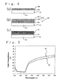
- this photoelectric conversion layer 26 (see FIG. 4(c) ) is obtained by carrying a sensitizing dye on a functional semiconductor layer 23 ⁇ obtained in the same manner as the functional semiconductor layer 23 ⁇ in the first embodiment, i.e., obtained by forming at least one coating film 23C (see FIG. 4(b) of an aqueous paste containing neither a binder nor an organic solvent and containing the group of the specific semiconductor particles on a layer 23B (see FIG. 4(a) ) obtained by subjecting a coating film of an aqueous paste containing neither a binder nor an organic solvent and containing the group of the specific semiconductor particles to the pressing treatment.
- the kinds and proportions of the group of the specific semiconductor particles contained in the aqueous paste for forming the coating film 23C of the aqueous paste may be the same or different from the kinds and proportions of the group of the specific semiconductor particles contained in the aqueous paste for forming the layer 23B obtained by subjecting the coating film to the pressing treatment.
- the layer thickness of the layer 23B obtained by subjecting the coating film to the pressing treatment is controlled to, for example, 1 to 20 ⁇ m, and the layer thickness of said at least one coating film 23C of the aqueous paste is controlled to, for example, 1 to 15 ⁇ m.
- this photoelectrode for dye-sensitized solar cell may be mentioned a process, in which as illustrated in FIG. 4(a) to FIG. 4(c) , the coating film 23C of the aqueous paste is formed on the layer 23B of the photoelectrode structure 20K formed in the first embodiment, i.e., a structure that the transparent conductive layer 21b and the layer 23B obtained by subjecting the coating film to the pressing treatment are formed in this order on the transparent base 21a, thereby forming a photoelectrode structure 20L, and a sensitizing dye is carried on a functional semiconductor layer 23 ⁇ in this photoelectrode structure 20L by the above-described method or the like.
- one to three coating films 23C of the aqueous paste are formed after the pressing treatment step (4) of the production process in the first embodiment, and the dye-carrying step (5) is then conducted.
- the pressing treatment for obtaining the layer 23B obtained by subjecting the coating film to the pressing treatment on the transparent substrate 21, which is conducted in a state that the coating film has been formed can be conducted under the same conditions as in the pressing treatment in the first embodiment. More specifically, the pressing treatment is preferably conducted under conditions that the light transmittance of a laminate of the layer 23B obtained by subjecting the coating film to the pressing treatment and the transparent substrate 21 at a wavelength of 400 to 800 nm reaches 105 to 170%, preferably 110 to 170%, particularly preferably 110 to 130% of a value before the pressing treatment.
- the pressing treatment is conducted under a pressure of, for example, 5 MPa or more, preferably 30 MPa or more, and a pressure of 500 MPa or less, preferably 150 MPa or less, whereby the above-described light transmittance can be realized, and the cracks unavoidably produced in the coating film of the aqueous paste can be filled. If the pressure in the pressing treatment is too high when a plastic transparent base is used in particular, the transparent base itself is distorted to adversely affect the performance of the resulting dye-sensitized solar cell, and moreover the transparent conductive layer formed on the transparent base may be broken. The too high pressure is hence not preferable.
- the pressing treatment is preferably conducted in such a manner that the thickness of the layer 23B obtained by subjecting the coating film to the pressing treatment, which makes up the functional conductive layer 23 ⁇ , is controlled to 80 to 30% of a value before the pressing treatment.
- an UV-ozone treatment may be conducted as a surface treatment on the functional semiconductor layer 23 ⁇ after the coating film 23C of the aqueous paste is laminated after the pressing treatment step and before the subsequent dye-carrying step in the same manner as in the first embodiment. This UV-ozone treatment may be conducted even when the UV-ozone treatment has been conducted or not conducted as the surface treatment on the transparent substrate 21.
- This UV-ozone treatment is considered to contribute to the fact that not only the surfaces of the semiconductor particles making up the functional semiconductor layer 23 ⁇ can be cleaned, but also hydrophilic groups of the semiconductor particles can be increased to create a state easy to adsorb the sensitizing dye. As a result, the photoelectric conversion efficiency of the resulting dye-sensitized solar cell can be made high.
- TMAH used in the preparation of the titania particles by the basic process in the aqueous paste-preparing step may remain as an unreacted compound in the functional semiconductor layer 23 ⁇ .
- this TMAH can be decomposed by the UV-ozone treatment to clean the surfaces of the semiconductor particles.
- the same effects as the photoelectric conversion element 10 of the first embodiment can be achieved.
- Tetraisopropyl orthotitanate (56.8 g) was added dropwise into ion-exchanged water (200 mL) under strong stirring, and the stirring was continued for additionally 1 hour after completion of the drop addition, thereby completing hydrolysis to obtain a precipitate of the intended titanium hydroxide.
- the precipitate was separated by filtration with filter paper and sufficiently washed with ion-exchanged water. This precipitate was added into ion-exchanged water, in which tetramethylammonium hydroxide (TMAH; 5.8 g) had been dissolved, and ion-exchanged water was further added in such a manner that the whole amount of a sample is 160 g.
- TMAH tetramethylammonium hydroxide
- An ethanol suspension [B] containing anatase crystal type titania particles [B] having an average particle diameter of 100 nm was obtained in the same manner as in this preparation process of semiconductor particle suspension except that the amount of TMAH added was changed to 1.5 g.
- D is a length of a crystallite
- ⁇ is a half value width
- ⁇ is an angle of diffraction
- K is 0.94
- ⁇ 1.5418.
- the ethanol suspensions were mixed in such a manner that a weight ratio of the titania particles [A] to the titania particles [B] is 7:3 on the basis of the respective concentrations, and the solvent of this mixture was almost completely replaced again by water by means of an evaporator, and the mixture was then concentrated, thereby finally obtaining an aqueous paste [1] for formation of a photoelectric conversion layer having a titania particle concentration of 10% by weight and containing water as a medium.
- This aqueous paste [1] for formation of photoelectric conversion layer was applied to a working electrode region of a size of 0.5 cm x 0.5 cm in a transparent substrate composed of an ITO/PEN (polyethylene naphthalate) substrate (product of Oji Tobi) having a sheet resistance of 13 ⁇ / ⁇ by a doctor blade method and then dried at room temperature to obtain a coating film.
- This coating film was subjected to a pressing treatment for 60 seconds under a pressure of 100 MPa, thereby obtaining a photoelectrode structure with a functional semiconductor layer formed on the transparent substrate.
- FIG. 5(b) illustrates a light transmittance of the transparent substrate, on which the coating film has been formed, before the pressing treatment.
- the coating film formed on the transparent substrate with the aqueous paste [1] for formation of photoelectric conversion layer before the pressing treatment was observed through SEM. As a result, it was observed that a great number of linear cracks having a length of about 10 to 100 ⁇ m in an SEM photograph of 1,000 magnifications are randomly formed. The cracks were further observed in an SEM photograph of 20,000 magnifications. As a result, it was confirmed that individual titania particles are present independently. On the other hand, SEM photographs of 1,000 and 20,000 magnifications after the pressing treatment were observed. As a result, almost all cracks formed in plenty were observed being filled, and the traces thereof were confirmed, and it was also observed that the titania particles are closely bonded to one another. The traces of the cracks filled by the pressing treatment are observed, whereby it is presumed that a contact area between the semiconductor particles and the transparent conductive layer is increased to improve the performance of the resultant dye-sensitized solar cell.
- the thus-fabricated dye-sensitized solar cell had extremely excellent performance, and the influence of TMAH was not observed. This is presumed to be attributable to the fact that if TMAH is present in the functional semiconductor layer after the pressing treatment, the photoelectrode structure is immersed in the ethanol solution of the sensitizing dye, whereby this TMAH is dissolved in ethanol and removed at the same time that the sensitizing dye is strongly bonded to the titania particles, and consequently TMAH is prevented from entering between the titania particles and between the titania particles and the transparent substrate.
- a dye-sensitized solar cell [2] was obtained in the same manner as in Example 1 except that the ethanol suspensions were mixed in such a manner that a weight ratio of the titania particles [A] to the titania particles [B] is 6:4.
- values of a short-circuit current, a release voltage, a form factor ff and a photoelectric conversion efficiency were obtained in the same manner as in Example 1.
- the results are shown in Table 1. Incidentally, the light transmittance of the functional semiconductor layer at a wavelength of 400 to 800 nm was increased to 130% of a value before the pressing treatment, and the layer thickness thereof was reduced to 70% and 7 ⁇ m.
- a dye-sensitized solar cell [3] was obtained in the same manner as in Example 2 except that an ITO/cycloolefin polymer substrate "ZEONOR Substrate” (product of ZEON CORPORATION) was used in place of the ITO/PEN substrate.
- ITO/cycloolefin polymer substrate "ZEONOR Substrate” (product of ZEON CORPORATION) was used in place of the ITO/PEN substrate.
- values of a short-circuit current, a release voltage, a form factor ff and a photoelectric conversion efficiency were obtained in the same manner as in Example 1. The results are shown in Table 1.
- a dye-sensitized solar cell [4] was obtained in the same manner as in Example 2 except that an ITO/heat-resistant acrylic substrate (product of The Nippon Synthetic Chemical Industry Co., Ltd.) was used in place of the ITO/PEN substrate.
- ITO/heat-resistant acrylic substrate product of The Nippon Synthetic Chemical Industry Co., Ltd.
- values of a short-circuit current, a release voltage, a form factor ff and a photoelectric conversion efficiency were obtained in the same manner as in Example 1. The results are shown in Table 1.
- a dye-sensitized solar cell [5] was obtained in the same manner as in Example 3 except that the working electrode region was changed to 0.5 cm x 4.5 cm, and the conditions of the pressing treatment were changed to a pressure of 80 MPa.
- values of a short-circuit current, a release voltage, a form factor ff and a photoelectric conversion efficiency were obtained in the same manner as in Example 1.
- the results are shown in Table 1. Incidentally, the light transmittance of the functional semiconductor layer at a wavelength of 400 to 800 nm was increased to 130% of a value before the pressing treatment, and the layer thickness thereof was reduced to 70% and 6 ⁇ m.
- a dye-sensitized solar cell [6] was obtained in the same manner as in Example 3 except that the working electrode region was changed to 0.5 cm x 9.0 cm, and the conditions of the pressing treatment were changed to a pressure of 80 MPa.
- values of a short-circuit current, a release voltage, a form factor ff and a photoelectric conversion efficiency were obtained in the same manner as in Example 1.
- the results are shown in Table 1. Incidentally, the light transmittance of the functional semiconductor layer at a wavelength of 400 to 800 nm was increased to 130% of a value before the pressing treatment, and the layer thickness thereof was reduced to 70% and 7 ⁇ m.
- a dye-sensitized solar cell [7] was obtained in the same manner as in Example 2 except that an ITO/conductive glass substrate having a sheet resistance of 9 ⁇ / ⁇ was used as the transparent substrate in place of the ITO/PEN substrate.
- values of a short-circuit current, a release voltage, a form factor ff and a photoelectric conversion efficiency were obtained in the same manner as in Example 1. The results are shown in Table 1. Incidentally, the layer thickness of the functional semiconductor layer was reduced to 70% and 5 ⁇ m.
- a comparative dye-sensitized solar cell [1] was obtained in the same manner as in Example 1 except that the pressing treatment was not conducted.
- values of a short-circuit current, a release voltage, a form factor ff and a photoelectric conversion efficiency were obtained in the same manner as in Example 1. The results are shown in Table 1.
- a comparative dye-sensitized solar cell [2] was obtained in the same manner as in Example 1 except that a commercially-available paste "PECC-01-06" (product of Peccell Technologies, Inc.) was used in place of the aqueous paste [1] for formation of photoelectric conversion layer, the pressing treatment was not conducted, and a heat treatment was conducted for 10 minutes at 150°C.
- a commercially-available paste "PECC-01-06" product of Peccell Technologies, Inc.
- a comparative dye-sensitized solar cell [3] was obtained in the same manner as in Example 1 except that the pressing treatment for the coating film was not conducted, and a heat treatment was conducted for 10 minutes at 150°C.
- values of a short-circuit current, a release voltage, a form factor ff and a photoelectric conversion efficiency were obtained in the same manner as in Example 1. The results are shown in Table 1.
- a comparative dye-sensitized solar cell [4] was obtained in the same manner as in Example 2 except that an ITO/conductive glass substrate having a sheet resistance of 9 ⁇ / ⁇ was used as the transparent substrate in place of the ITO/PEN substrate, the pressing treatment was not conducted, a calcining treatment was conducted for 1 hour at 520°C after the aqueous paste [1] for formation of photoelectric conversion layer was applied and dried, and a counter electrode obtained by sputtering platinum on conductive glass was used.
- values of a short-circuit current, a release voltage, a form factor ff and a photoelectric conversion efficiency were obtained in the same manner as in Example 1. The results are shown in Table 1.
- a comparative dye-sensitized solar cell [5] was obtained in the same manner as in Example 1 except that a comparative aqueous paste [Y] for formation of photoelectric conversion layer prepared by mixing the two kinds of ethanol suspensions [A] and [B] in such a manner that a weight ratio of the titania particles [A] to the titania particles [B] is 6:4, adding ethyl cellulose and ⁇ -terpineol to this mixture, uniformly dispersing the mixture by a homogenizer and an ultrasonic disperser and then concentrating the resultant dispersion by a rotary evaporator was used in place of the aqueous paste [1] for formation of photoelectric conversion layer, and a comparative photoelectrode fabricated by conducting printing on conductive glass having a sheet resistance of 9 ⁇ / ⁇ with this comparative aqueous paste [Y] for formation of photoelectric conversion layer by means of a screen printer so as to give a working electrode region of 0.5 cm x 0.5 cm and
- a comparative dye-sensitized solar cell [6] was obtained in the same manner as in Example 1 except that a comparative aqueous paste [Z] for formation of photoelectric conversion layer composed of the titania particles [A] alone was used in place of the aqueous paste [1] for formation of photoelectric conversion layer.
- a comparative dye-sensitized solar cell [6] values of a short-circuit current, a release voltage, a form factor ff and a photoelectric conversion efficiency were obtained in the same manner as in Example 1. The results are shown in Table 1. Incidentally, the light transmittance of the functional semiconductor layer at a wavelength of 400 to 800 nm was increased to 130% of a value before the pressing treatment, and the layer thickness thereof was reduced to 70% and 7 ⁇ m.
- a comparative aqueous paste [W] for formation of photoelectric conversion layer composed of a total amount of 10% by weight of the titania particles [A] and the titania particles [B], hydroxypropyl cellulose (0.5% by weight), and water and containing the titania particles [A] and the titania particles [B] at a weight ratio of 7:3 was
- the dye-sensitized solar cells of Examples 1 to 7 according to the present invention achieve a high photoelectric conversion efficiency.
- the reason why the dye-sensitized solar cell [1] of Example 1 exhibits a high photoelectric conversion efficiency compared with the dye-sensitized solar cells of the other Examples 2 to 7 is considered to be attributable to the fact that the value of the form factor ff is high, that is, the adhesion between the titania particles and the transparent substrate is good.
- Example 1 When the results of Example 1 were compared with the results of Comparative Example 5 relating to the comparative dye-sensitized solar cell obtained by using the glass substrate as the transparent substrate and the binder-containing paste and conducting calcination at a high temperature, which has heretofore been conducted, it was confirmed that the dye-sensitized solar cell according to the present invention exhibits a photoelectric conversion efficiency equal to or more than the conventional dye-sensitized solar cell using the glass substrate. When the results of Examples 1, 3 and 4 were compared with one another, it was indicated that a difference in material between the transparent bases each forming the transparent substrate affects the degree of the photoelectric conversion efficiency.
- a dye-sensitized solar cell (a) was obtained in the same manner as in Example 1 except that the two kinds of ethanol suspensions [A] and [B] were mixed in such a manner that a weight ratio of the titania particles [A] to the titania particles [B] is 6:4, and the conditions of the pressing treatment were changed to a pressure of 80 MPa (gauge pressure; 4 MPa).
- a pressure of 80 MPa gauge pressure; 4 MPa
- light transmittances (absolute values) at wavelengths of 400 nm, 500 nm, 600 nm, 700 nm and 800 nm were measured. The results are shown in Table 2.
- a dye-sensitized solar cell (b) was obtained in the same manner as in Example 9 except that the conditions of the pressing treatment were changed to a pressure of 160 MPa (gauge pressure; 8 MPa). With respect to the photoelectrode structure [b] of this dye-sensitized solar cell [b], light transmittances (absolute values) at wavelengths of 400 nm, 500 nm, 600 nm, 700 nm and 800 nm were measured. The results are shown in Table 2.
- a dye-sensitized solar cell (c) was obtained in the same manner as in Example 1 except that the conditions of the pressing treatment were changed to a pressure of 80 MPa (gauge pressure; 4 MPa). With respect to the photoelectrode structure [c] of this dye-sensitized solar cell [c], light transmittances (absolute values) at wavelengths of 400 nm, 500 nm, 600 nm, 700 nm and 800 nm were measured. The results are shown in Table 2.
- a dye-sensitized solar cell (d) was obtained in the same manner as in Example 10 except that the conditions of the pressing treatment were changed to a pressure of 160 MPa (gauge pressure; 8 MPa). With respect to the photoelectrode structure [d] of this dye-sensitized solar cell [d], light transmittances (absolute values) at wavelengths of 400 nm, 500 nm, 600 nm, 700 nm and 800 nm were measured. The results are shown in Table 2.
- a referential dye-sensitized solar cell [e] was obtained in the same manner as in Example 1 except that only the titania particles [A] were used, and the conditions of the pressing treatment were changed to a pressure of 80 MPa (gauge pressure; 4 MPa).
- a pressure of 80 MPa gauge pressure; 4 MPa.
- light transmittances (absolute values) at wavelengths of 400 nm, 500 nm, 600 nm, 700 nm and 800 nm were measured. The results are shown in Table 2.
- a referential dye-sensitized solar cell [f] was obtained in the same manner as in Referential Example 1 except that the conditions of the pressing treatment were changed to a pressure of 160 MPa (gauge pressure; 8 MPa). With respect to the photoelectrode structure [f] of this referential dye-sensitized solar cell [f], light transmittances (absolute values) at wavelengths of 400 nm, 500 nm, 600 nm, 700 nm and 800 nm were measured. The results are shown in Table 2.
- a reverse-sputtering (etching) treatment was conducted under conditions of 20 W and 10 minutes. Specifically, a high-frequency ac voltage was applied, thereby generating plasma, and an argon atom charged with a plus charge in the plasma was caused to collide with the substrate charged with a minus charge, thereby removing the deposits on the substrate.
- An object of the treatment was placed in an UV-ozone cleaning apparatus "OC-2506" (manufactured by IWASAKI ELECTRIC CO., LTD.), and the object was irradiated with ultraviolet light for 5 minutes.
- the UV-ozone treatment conducted as the surface treatment shows a tendency to achieve a high photoelectric conversion efficiency compared with the case where the ultrasonic cleaning treatment or etching treatment is conducted.
- the reason for it is considered to be attributable to the fact that ozone generated by ultraviolet light decomposes and removes organic pollutants on the surface of the object of the treatment, and moreover active oxygen from the ozone is bonded to surface molecules to increase the hydrophilicity of the surface of the object of the treatment, whereby the contact angle of water is greatly reduced compared with that before the surface treatment, and consequently the adhesion of the aqueous paste to the transparent substrate is increased.
- Dye-sensitized solar cells [24] and [25] were fabricated in the same manner as in Example 1 except that an UV-ozone treatment was conducted on the functional semiconductor layer after the pressing treatment and before the dye-carrying step, and a mixed solvent containing acetonitrile and t-butyl alcohol at a weight ratio of 1:1 was used as the solvent used in the dye-carrying step.
- the layer thicknesses of the functional semiconductor layers making up these dye-sensitized solar cells [24] and [25] were 7.6 ⁇ m and 8.1 ⁇ m. respectively.
- the dye-sensitized solar cell according to the present invention can retain a high level of photoelectric conversion efficiency even when the quantity of incident light is changed.
- a dye-sensitized solar cell fabricated in the same manner as in Example 1 was used, and the quantity of incident light was changed within a range of 20 to 200 mW/cm 2 to measure a photoelectric conversion efficiency when the quantity of incident light was controlled to 23 mW/cm 2 , 48.5 mW/cm 2 , 70 mW/cm 2 , 100 mW/cm 2 or 170 mW/cm 2 .
- Table 5 The results are shown in Table 5.
- Table 6 The results are shown in Table 6.
Applications Claiming Priority (2)
| Application Number | Priority Date | Filing Date | Title |
|---|---|---|---|
| JP2006056422 | 2006-03-02 | ||
| PCT/JP2007/054042 WO2007100095A1 (ja) | 2006-03-02 | 2007-03-02 | 色素増感型太陽電池用光電極の製造方法および色素増感型太陽電池用光電極、並びに色素増感型太陽電池 |
Publications (1)
| Publication Number | Publication Date |
|---|---|
| EP2006949A2 true EP2006949A2 (de) | 2008-12-24 |
Family
ID=38459190
Family Applications (1)
| Application Number | Title | Priority Date | Filing Date |
|---|---|---|---|
| EP07737690A Withdrawn EP2006949A2 (de) | 2006-03-02 | 2007-03-02 | Verfahren zum herstellen einer fotoelektrode für eine farbstoffsensibilisierte solarzelle, fotoelektrode für eine farbstoffsensibilisierte solarzelle und farbstoffsensibilisierte solarzelle |
Country Status (4)
| Country | Link |
|---|---|
| US (1) | US20090114277A1 (de) |
| EP (1) | EP2006949A2 (de) |
| JP (2) | JP4446011B2 (de) |
| WO (1) | WO2007100095A1 (de) |
Cited By (1)
| Publication number | Priority date | Publication date | Assignee | Title |
|---|---|---|---|---|
| WO2011029145A1 (en) * | 2009-09-10 | 2011-03-17 | Monash University | Method of manufacturing mesoscopic solar cells |
Families Citing this family (14)
| Publication number | Priority date | Publication date | Assignee | Title |
|---|---|---|---|---|
| JP5354960B2 (ja) * | 2008-05-30 | 2013-11-27 | 日揮触媒化成株式会社 | 光電気セル用多孔質金属酸化物半導体膜形成用塗料および光電気セル |
| JP2010140812A (ja) * | 2008-12-12 | 2010-06-24 | Sekisui Chem Co Ltd | 機能素子及びその製造方法並びに色素増感太陽電池 |
| JP5630745B2 (ja) * | 2010-01-07 | 2014-11-26 | 日新製鋼株式会社 | 色素増感型太陽電池用光電極の製造方法 |
| JP2012146420A (ja) * | 2011-01-07 | 2012-08-02 | Toppan Printing Co Ltd | 色素増感太陽電池および色素増感太陽電池の製造方法 |
| JP5358790B2 (ja) * | 2011-05-11 | 2013-12-04 | ペクセル・テクノロジーズ株式会社 | 色素増感型光電変換素子用光電極及びその製造方法 |
| EP2712683B1 (de) * | 2011-05-20 | 2018-12-19 | National Institute of Advanced Industrial Science And Technology | Filmherstellungsverfahren |
| JP2013026082A (ja) * | 2011-07-22 | 2013-02-04 | Sony Corp | 光電変換装置、電子機器および建築物 |
| JP5408596B2 (ja) * | 2011-11-25 | 2014-02-05 | 学校法人東京理科大学 | 色素増感太陽電池用光電極および色素増感太陽電池 |
| US20150040976A1 (en) | 2012-01-05 | 2015-02-12 | Council Of Scientific And Industrial Research | Method for preparing solar paint at room temperature for dye sensitized solar cells for window panes and flexible substrates |
| EP2913883A4 (de) | 2012-10-23 | 2015-10-14 | Univ Tokyo Sci Educ Found | Photoelektrode für farbstoffsensibilisierte solarzellen und farbstoffsensibilisierte solarzelle |
| EP3113240B1 (de) | 2014-02-24 | 2024-04-03 | Ricoh Company, Ltd. | Photoelektrisches umwandlungselement und solarzelle |
| JP6337561B2 (ja) | 2014-03-27 | 2018-06-06 | 株式会社リコー | ペロブスカイト型太陽電池 |
| CN109608055B (zh) * | 2018-12-29 | 2021-08-20 | 河南科技大学 | 一种硫化铋敏化的二氧化钛纳米棒薄膜及其制备方法 |
| CN109704595B (zh) * | 2019-02-19 | 2021-08-24 | 河南科技大学 | 一种硫化铋/二氧化钛复合材料薄膜及其制备方法与应用 |
Family Cites Families (9)
| Publication number | Priority date | Publication date | Assignee | Title |
|---|---|---|---|---|
| SE514600C2 (sv) * | 1999-05-25 | 2001-03-19 | Forskarpatent I Uppsala Ab | Metod för tillverkning av nanostrukturerade tunnfilmselektroder |
| US6881604B2 (en) * | 1999-05-25 | 2005-04-19 | Forskarpatent I Uppsala Ab | Method for manufacturing nanostructured thin film electrodes |
| JP2001093591A (ja) * | 1999-09-28 | 2001-04-06 | Toshiba Corp | 光電変換素子 |
| JP4470370B2 (ja) | 2003-01-08 | 2010-06-02 | ソニー株式会社 | 光電変換素子の製造方法 |
| JP4247820B2 (ja) * | 2003-02-12 | 2009-04-02 | 富士フイルム株式会社 | 光電変換素子の作製方法及び光電変換素子 |
| JP4576544B2 (ja) * | 2003-07-31 | 2010-11-10 | 学校法人桐蔭学園 | フィルム型色素増感光電池 |
| JP4824913B2 (ja) * | 2004-02-17 | 2011-11-30 | 国立大学法人京都大学 | グラフト薄膜を用いた光電素子及び太陽電池 |
| JP2006012517A (ja) * | 2004-06-24 | 2006-01-12 | Toppan Printing Co Ltd | 金属酸化物構造体及び色素増感太陽電池 |
| JP4556232B2 (ja) | 2004-06-30 | 2010-10-06 | 日新電機株式会社 | 色素増感太陽電池及びその製造方法 |
-
2007
- 2007-03-02 US US12/224,647 patent/US20090114277A1/en not_active Abandoned
- 2007-03-02 WO PCT/JP2007/054042 patent/WO2007100095A1/ja active Search and Examination
- 2007-03-02 EP EP07737690A patent/EP2006949A2/de not_active Withdrawn
- 2007-03-02 JP JP2008502871A patent/JP4446011B2/ja not_active Expired - Fee Related
-
2008
- 2008-05-28 JP JP2008139276A patent/JP2008288209A/ja not_active Withdrawn
Non-Patent Citations (1)
| Title |
|---|
| See references of WO2007100095A1 * |
Cited By (1)
| Publication number | Priority date | Publication date | Assignee | Title |
|---|---|---|---|---|
| WO2011029145A1 (en) * | 2009-09-10 | 2011-03-17 | Monash University | Method of manufacturing mesoscopic solar cells |
Also Published As
| Publication number | Publication date |
|---|---|
| US20090114277A1 (en) | 2009-05-07 |
| JP4446011B2 (ja) | 2010-04-07 |
| JP2008288209A (ja) | 2008-11-27 |
| JPWO2007100095A1 (ja) | 2009-07-23 |
| WO2007100095A1 (ja) | 2007-09-07 |
Similar Documents
| Publication | Publication Date | Title |
|---|---|---|
| EP2006949A2 (de) | Verfahren zum herstellen einer fotoelektrode für eine farbstoffsensibilisierte solarzelle, fotoelektrode für eine farbstoffsensibilisierte solarzelle und farbstoffsensibilisierte solarzelle | |
| Kay et al. | Low cost photovoltaic modules based on dye sensitized nanocrystalline titanium dioxide and carbon powder | |
| Miyasaka et al. | Low-temperature fabrication of dye-sensitized plastic electrodes by electrophoretic preparation of mesoporous TiO2 layers | |
| JP5002595B2 (ja) | 色素増感太陽電池モジュールおよびその製造方法 | |
| JP2008251519A (ja) | 色素増感型太陽電池用光電極および色素増感型太陽電池 | |
| JP2005235725A (ja) | 色素増感型太陽電池モジュール | |
| JP4576544B2 (ja) | フィルム型色素増感光電池 | |
| CA2878406C (en) | Photoelectrically convertible composition comprising an anionic polymer, a laminate, and processes therefor | |
| JP2006024574A (ja) | 色素増感型太陽電池モジュール | |
| JP5128118B2 (ja) | 湿式太陽電池とその製造方法 | |
| JP2005158379A (ja) | 光電変換素子およびその製造方法ならびに電子装置およびその製造方法 | |
| JP4892186B2 (ja) | 色素増感太陽電池および色素増感太陽電池モジュール | |
| WO2013164967A1 (ja) | 光電変換素子および光電変換モジュール | |
| JP4883559B2 (ja) | 光電変換電極 | |
| JP4155431B2 (ja) | 光電変換素子 | |
| WO2013077209A1 (ja) | 湿式太陽電池および湿式太陽電池モジュール | |
| JP5189869B2 (ja) | 電解液及び色素増感型太陽電池 | |
| WO2012086377A1 (ja) | 色素増感太陽電池および色素増感太陽電池モジュールならびにその製造方法 | |
| KR20120080796A (ko) | 다기능 산화물층을 포함한 염료감응 태양전지 및 이의 제조방법 | |
| Maharjan | Comparative study of characteristics of dye sensitized solar cells fabricated using substrates coated with fluorine doped tin oxide and titanium | |
| KR101554445B1 (ko) | 색소 증감 태양 전지용 광 전극 및 그 제조 방법, 및 색소 증감 태양 전지 | |
| WO2013114733A1 (ja) | 光電変換素子モジュール | |
| JP6015929B2 (ja) | 色素増感太陽電池用光電極および色素増感太陽電池 | |
| KR20120121940A (ko) | 저온 대기압 플라즈마를 통한 광전극 및 염료감응 태양전지 제조 방법 | |
| Amornkitbamrung | A dye sensitized solar cell using natural counter electrode and natural dye derived from mangosteen peel waste |
Legal Events
| Date | Code | Title | Description |
|---|---|---|---|
| PUAI | Public reference made under article 153(3) epc to a published international application that has entered the european phase |
Free format text: ORIGINAL CODE: 0009012 |
|
| PUAB | Information related to the publication of an a document modified or deleted |
Free format text: ORIGINAL CODE: 0009199EPPU |
|
| 17P | Request for examination filed |
Effective date: 20081002 |
|
| AK | Designated contracting states |
Kind code of ref document: A2 Designated state(s): DE FR GB |
|
| RBV | Designated contracting states (corrected) |
Designated state(s): DE FR GB |
|
| DAX | Request for extension of the european patent (deleted) | ||
| STAA | Information on the status of an ep patent application or granted ep patent |
Free format text: STATUS: THE APPLICATION HAS BEEN WITHDRAWN |
|
| 18W | Application withdrawn |
Effective date: 20160301 |