EP2003270A2 - Système et procédé de fixation d'un objet en forme de mât ou de poteau dans le sol en terre avec une partie réceptrice en plusieurs pièces pouvant être vissées sur le sol en terre - Google Patents
Système et procédé de fixation d'un objet en forme de mât ou de poteau dans le sol en terre avec une partie réceptrice en plusieurs pièces pouvant être vissées sur le sol en terre Download PDFInfo
- Publication number
- EP2003270A2 EP2003270A2 EP08104331A EP08104331A EP2003270A2 EP 2003270 A2 EP2003270 A2 EP 2003270A2 EP 08104331 A EP08104331 A EP 08104331A EP 08104331 A EP08104331 A EP 08104331A EP 2003270 A2 EP2003270 A2 EP 2003270A2
- Authority
- EP
- European Patent Office
- Prior art keywords
- receiving
- receiving elements
- receiving part
- sleeve
- fastening system
- Prior art date
- Legal status (The legal status is an assumption and is not a legal conclusion. Google has not performed a legal analysis and makes no representation as to the accuracy of the status listed.)
- Granted
Links
- 238000000034 method Methods 0.000 title claims abstract description 11
- 239000004576 sand Substances 0.000 claims abstract description 5
- 239000013590 bulk material Substances 0.000 claims abstract 2
- 239000000463 material Substances 0.000 claims description 28
- 230000013011 mating Effects 0.000 claims description 21
- 239000002689 soil Substances 0.000 claims description 17
- 239000004033 plastic Substances 0.000 claims description 10
- 229920003023 plastic Polymers 0.000 claims description 10
- 238000009434 installation Methods 0.000 claims description 6
- 238000009415 formwork Methods 0.000 claims description 5
- 239000008187 granular material Substances 0.000 claims description 5
- -1 split Substances 0.000 claims description 4
- 229910000831 Steel Inorganic materials 0.000 claims description 3
- 239000010959 steel Substances 0.000 claims description 3
- 239000007769 metal material Substances 0.000 claims description 2
- 230000003068 static effect Effects 0.000 claims 1
- 239000000945 filler Substances 0.000 abstract description 9
- 238000003780 insertion Methods 0.000 description 14
- 230000037431 insertion Effects 0.000 description 14
- 238000013461 design Methods 0.000 description 13
- 230000008901 benefit Effects 0.000 description 6
- 239000000203 mixture Substances 0.000 description 4
- 230000006978 adaptation Effects 0.000 description 3
- 238000004873 anchoring Methods 0.000 description 2
- 230000005540 biological transmission Effects 0.000 description 2
- 239000002184 metal Substances 0.000 description 2
- 230000003716 rejuvenation Effects 0.000 description 2
- 239000007787 solid Substances 0.000 description 2
- 238000003860 storage Methods 0.000 description 2
- 238000012546 transfer Methods 0.000 description 2
- 239000004952 Polyamide Substances 0.000 description 1
- 239000004698 Polyethylene Substances 0.000 description 1
- 239000004743 Polypropylene Substances 0.000 description 1
- 239000004793 Polystyrene Substances 0.000 description 1
- 230000001427 coherent effect Effects 0.000 description 1
- 238000010276 construction Methods 0.000 description 1
- 230000008878 coupling Effects 0.000 description 1
- 238000010168 coupling process Methods 0.000 description 1
- 238000005859 coupling reaction Methods 0.000 description 1
- 230000001186 cumulative effect Effects 0.000 description 1
- 230000001419 dependent effect Effects 0.000 description 1
- 238000011161 development Methods 0.000 description 1
- 238000009792 diffusion process Methods 0.000 description 1
- 238000006073 displacement reaction Methods 0.000 description 1
- 238000009826 distribution Methods 0.000 description 1
- 239000002657 fibrous material Substances 0.000 description 1
- 230000000977 initiatory effect Effects 0.000 description 1
- 239000007788 liquid Substances 0.000 description 1
- 238000004519 manufacturing process Methods 0.000 description 1
- 230000000149 penetrating effect Effects 0.000 description 1
- 229920002647 polyamide Polymers 0.000 description 1
- 229920000573 polyethylene Polymers 0.000 description 1
- 229920001155 polypropylene Polymers 0.000 description 1
- 229920002223 polystyrene Polymers 0.000 description 1
- 239000011435 rock Substances 0.000 description 1
- 239000004575 stone Substances 0.000 description 1
- 238000012549 training Methods 0.000 description 1
- 238000009827 uniform distribution Methods 0.000 description 1
- 239000002023 wood Substances 0.000 description 1
Images


Classifications
-
- E—FIXED CONSTRUCTIONS
- E04—BUILDING
- E04H—BUILDINGS OR LIKE STRUCTURES FOR PARTICULAR PURPOSES; SWIMMING OR SPLASH BATHS OR POOLS; MASTS; FENCING; TENTS OR CANOPIES, IN GENERAL
- E04H12/00—Towers; Masts or poles; Chimney stacks; Water-towers; Methods of erecting such structures
- E04H12/22—Sockets or holders for poles or posts
- E04H12/2207—Sockets or holders for poles or posts not used
- E04H12/2215—Sockets or holders for poles or posts not used driven into the ground
- E04H12/2223—Sockets or holders for poles or posts not used driven into the ground by screwing
-
- E—FIXED CONSTRUCTIONS
- E02—HYDRAULIC ENGINEERING; FOUNDATIONS; SOIL SHIFTING
- E02D—FOUNDATIONS; EXCAVATIONS; EMBANKMENTS; UNDERGROUND OR UNDERWATER STRUCTURES
- E02D5/00—Bulkheads, piles, or other structural elements specially adapted to foundation engineering
- E02D5/74—Means for anchoring structural elements or bulkheads
- E02D5/80—Ground anchors
- E02D5/801—Ground anchors driven by screwing
Definitions
- the receiving part then serves only in the form of a formwork to hold the filler together, to diffuse into the surrounding soil and thus to prevent loosening of the anchorage and to support a consolidating setting of the filling material.
- the receiving part is supported even in this installed state to the outside of the solidifying soil, which in turn can not compress the receiving part, because its interior is then filled and stiffened by the filling material and the lower end of the rod-shaped part.
- the modular design of the receiving part is suitable for all known forms of screw foundations, regardless of whether they are cylindrical open at the bottom, tapered towards the lower end tapered or truncated cone shaped with lower opening.
- the simplest is the downwardly open, cylindrical shape, since it requires only one, namely a cylindrical sleeve-like receiving element, which can be assembled in the necessary majority to the correspondingly sized holding part.
- the receiving part can be formed from a sleeve-like receiving element cylindrical contour and / or a receiving element cone or frusto-conical contour and a receiving element as the upper closing element with or without external thread, which requires a corresponding element as a further element.
- the non-rotatable connection results, for example, without further ado, when the receiving elements in the positive connection, approximately in cross-section as a polygon, are plugged into each other.
- the tensile and shear-resistant connection can be realized in a simple manner by clip connections in the region of the connector.
- ribs may be formed on the inside of the receiving elements, which extend in the longitudinal direction of the receiving elements and engage in corresponding longitudinal grooves of the fitting core.
- this full-surface contact should be ensured, at least in the case of receiving elements which require a full-surface installation of the dowel core for screwing in, that the receiving parts are now plugged together or loose mounted on the dowel core - over the entire length of the formed receiving part (with the exception of one area tapered inner contour in a cone or truncated cone-shaped receiving element) have a substantially continuous inner cross-section.
- This is the only way to ensure that a screwing-in tool with a dimensionally stable fitting core corresponding outer contour can bring in a screwing of the receiving parts placed thereon into the ground with the greatest possible uniform distribution of the forces acting thereon.
- an area of tapered inner contour in a conical or frusto-conical receiving element merely takes into account the fact that, in the conical region, there is naturally no “continuously variable cross-section".
- the screwing tool or its mating core should, of course, also be adapted as far as possible in its outer contour to the inner contour of the conical or frusto-conical receiving element in this area, so that this part of a receiving element as fully as possible with the mating core in contact can be brought, the opposing shapes are to be avoided in any case.
- the outer contour of the dimensionally stable fitting core of the screw-in tool corresponds to the inner contour of the receiving elements or their passages.
- the coupling between the sleeve-like receiving elements and the dowel core can then be carried out, for example, in such a way that - as in DE 10 2005 023 465 B3 described in more detail - formed on the outer circumference of the sleeve-like receiving elements threads to the interior of the receiving element are open and form a helical profiling, which is adapted to an external thread, which is formed on the outer circumference of the dowel core, wherein the engagement and disengagement of receiving elements and Pass core is made by oppositely directed rotational movements.
- the fastening system according to the invention can only develop its full benefits if the dimensionally stable fitting core has a length corresponding to the maximum number or the total length of the maximum number of receiving elements to be combined in a practical use to a receiving part.
- a thin-walled receiving element is naturally mechanically most endangered when it is introduced into the ground in the region of its penetrating into the ground tip. Therefore, it can further be provided that the sleeve-like receiving elements form an insert body with inserted fitting core together with this insert body which ends in its direction of the ground facing in a cone which is partially or completely formed by the sleeve-like receiving elements in the direction of insertion passport core. After insertion of the insert body in the ground of the fitting core is removed again, so that only serve as formwork receiving elements remain in the ground.
- the dowel core of the insertion tool thus engages through the hollow sleeve-like receiving element until it projects with the tip of its cone down from the lower in the screw-in receiving element.
- the insert body consisting of the fitting core and the receiving elements penetrates into the ground with the tip of the fitting core first. Since the receiving part or its elements is usually a mass portion that can only be used once or are, however, the insertion tool can be used over and over again, it is worthwhile to form this insertion tool of a resistant material in high quality, so that it with its tip can serve many times as an indenter into the ground.
- the materials suitable for the receiving elements and the fitting core of the insertion tool are based on the particular application.
- the fitting core of the insertion tool consists of a metal material, preferably of steel, while for the sleeve-like receiving elements in each case a plastic comes into question.
- Suitable plastics are, for example, polyamides, polypropylenes, polyethylenes and polystyrenes, which are listed in the here Sequence at the same time mean an increasing life of the receiving elements in the ground.
- a filling material is part of the fastening system
- free-flowing materials such as sand, split or quarry stone, but also granules, for example of plastic, are particularly suitable for this purpose.
- concrete can also be used.
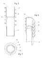
- FIG. 1 Assembled shown consists of a cylindrical receiving element 5, a (partially) frusto-conical receiving element 6, in its place also a (partially) conically downwardly tapered receiving element 6 can occur, and a receiving element as upper end element. 7
- the first-mentioned receiving elements 5, 6 have an external thread 2, is omitted in the upper end element 7 on the external thread 2.
- the sleeve-like receiving part for example, consist only of a plurality of cylindrical receiving elements 5. But it may also consist of several such elements and a (completely or partially) conical or frusto-conical shaped receiving element 6 or of such a and a receiving element as upper end element 7 Finally, it may consist of a (full or partial) cone or truncated cone-shaped receiving element. 6 and a receiving element as the upper end element 7 are formed.
- all elements can have an external thread 2.
- the receiving element as upper end element 7, corresponding elements without external thread belong, which can be used in a suitable case in the combination of elements, for example, between two elements with external thread.
- the receiving elements 5, 6, 7 can be designed thick-walled or thin-walled self-supporting, in which case their adaptation to the Outside profile of the fitting core 4 of a Einschraubtechnikmaschinees 3 not only via a corresponding design of the wall of the receiving elements 5, 6, 7 directly, but also by the installation of correspondingly shaped ribs or passages 8 can be done, as shown in the FIGS. 5 to 9 is shown in more detail.
- the receiving elements 5, 6, 7 can also be so thin-walled that they can not easily transfer the forces and moments occurring when screwing. Then must - as in particular in the Figures 10 and 11 is shown in more detail - a dimensionally stable fitting core 4 of the system belonging screwing tool 3, to which they are plugged, be shaped so that it largely fills the receiving elements by positive fit and supports, so that they get their required for screwing into the soil dimensional stability and the forces and / or moments required for screwing in are transferred to it as uniformly as possible over a large area.
- the receiving elements 5, 6, 7 can be connected to each other, for example by training of tapered plug-in areas 11 and unused plug-in areas 12 plugged into each other and / or be locked together.
- a rotationally fixed connection for example, be generated in that the nestable receiving elements 5, 6, 7 - as shown in the drawings - have a polygonal cross-section.
- Such a connection may be useful when it is necessary to transfer forces from one to the other receiving element 5, 6, 7 or even to facilitate the handling of the multiple parts that are assembled into a receiving part 1.
- the receiving elements 5, 6, 7 can also be screwed into the ground without connection to one another, where they then inter alia by the external thread - Are anchored so that they no longer change their position even after removing the Einschraubwerkmaschinectiones 3.
- the internal cross-section of the receiving elements 5, 6, 7 must be designed to be continuously uniform in the axial direction.
- Only the conical or partially conical region of the conical or frusto-conical receiving element 6 allows, as this receiving element 6 is used only as a lower end - a different, for example conical design of the inner Cross-section and the corresponding part of the outer cross-section of the mating core 4.
- a corresponding - for example, conical - design of the outer contour of the mating core. 4 and the inner contour of the receiving element 6, as in FIG. 10 and 11 is shown.
- FIG. 2 shows the composition of receiving elements 5, 6, 7 after FIG. 1 in their to a sleeve-like receiving part 1 rotatable, push and pull together assembled form.
- FIG. 3 shows a cross section through the composition of receiving elements 5, 6, 7 according to FIG. 1 ,
- locking elements 9, 10 as locking grooves 9 and locking lugs 10 are better recognizable.
- the receiving elements 5, 6, 7 can be designed in their plug-in areas 11, 12 such that, when plugged together, a continuously uniform inner cross-section results in the axial direction.
- FIG. 4 shows a cross section through the mated receiving part 1 after FIG. 2 .
- each receiving element 5, 6, 7 of the fastening system corresponding passages 8 may also have a plurality of such passages 8.
- passages 8 define the free inner cross-section of the receiving elements 5, 6, 7, in which - so that the Aufsteckiana the receiving elements 5, 6, 7 is ensured on the passport core - nothing may protrude.
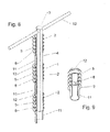
- FIG. 5 also shows the plug-in areas 11, 12 of the receiving element 5, here in the form of a (in the installation direction lower) cross-sectional taper 11 and an upper, unperforated cross-section 12.
- the upper, unperforated cross-section 12 of the or a receiving part 5, 6, 7 allows the insertion of the correspondingly tapered lower plug-in portion 11 of another receiving element 5, 7 and the lower, tapered plug portion 11 of the or a receiving element 5, 7 allows its insertion into the upper, unused plug portion 12 of the receiving elements 5, 6, 7th
- rejuvenated and unused plug-in area can also be interchanged.
- tapered plug-in portion 11 remains in its internal cross-section outside the cross section of the passages 8, so that the insertion of the passport core 4 by the receiving elements 5, 6, 7 or through the passages 8 is not hindered.
- FIG. 7 shows a cross section through the cylindrical receiving element 5 after FIGS. 5 and 6 in the region of its passage 8 with external thread 2, polygon-shaped passage 8, tapered plug-in area 11 and non-tapered plug-in area 12.
- FIG. 8 shows an inventive Einschraubtechnik Weg 3 with a fitting core 4 in the form of a hexagon, a handle 13 and with three plugged thereon, cut cylindrical receiving elements 5 with external thread 2, each having a polygonal passage 8 with a polygon of the fitting core 4 corresponding inner cross-section ,
- the receiving elements 5 can be seen their tapered plug-in areas 11 and their unused plug-in areas 12, but are unconnected plugged onto the mating core 4.
- FIG. 9 shows one of the cylindrical receiving elements FIG. 8 , partially cut, with external thread 2, polygon-shaped passage 8, tapered plug-in area 11 and non-tapered plug-in area 12.
- FIG. 10 shows the composition of receiving elements 5, 6, 7 after FIG. 1 in the assembled to a receiving part 1 form according to FIG. 2 and the associated Einschraubtechnikmaschine 3 with fitting core 4 in a perspective view.
- the screw-in tool 3 has at its upper end an insertion opening 14 for a handle 13, a fitting core 4, which merges as an octagon with broken edges down into a conical shape 15.
- FIG. 11 shows the screw 3 after FIG. 10 with attached receiving part 1 after FIG. 10 in perspective and partially cut.
- the drill bit 16 the receiving part 1 orientaldingt and protrudes down therefrom as a drill bit.
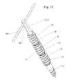
- FIG. 12 shows a unit of Einschraubwerkmaschine 3 and mounted thereon receiving part 1 in a perspective view.
- the screw-3 is provided here with a handle 13.
- Its mating core 4 is formed as a hexagon.
- Receiving elements 5 attached on it are the cylindrical ones Receiving elements 5 attached.
- the screwing-in tool 3 penetrates the receiving elements 5 or the receiving part 1 formed from them and merges at its lower, near-earth end into a conical bore extension 17 with outer spiral.
Landscapes
- Engineering & Computer Science (AREA)
- Structural Engineering (AREA)
- Architecture (AREA)
- Civil Engineering (AREA)
- Mining & Mineral Resources (AREA)
- General Life Sciences & Earth Sciences (AREA)
- Life Sciences & Earth Sciences (AREA)
- Paleontology (AREA)
- General Engineering & Computer Science (AREA)
- Forms Removed On Construction Sites Or Auxiliary Members Thereof (AREA)
- Mutual Connection Of Rods And Tubes (AREA)
- Foundations (AREA)
- Piles And Underground Anchors (AREA)
Applications Claiming Priority (1)
| Application Number | Priority Date | Filing Date | Title |
|---|---|---|---|
| DE200710027545 DE102007027545B4 (de) | 2007-06-15 | 2007-06-15 | System und Verfahren zum Befestigen eines stab- oder pfostenförmigen Gegenstandes im Erdboden mit in den Erdboden einschraubbarem mehrteiligen Aufnahmeteil |
Publications (3)
| Publication Number | Publication Date |
|---|---|
| EP2003270A2 true EP2003270A2 (fr) | 2008-12-17 |
| EP2003270A3 EP2003270A3 (fr) | 2014-01-22 |
| EP2003270B1 EP2003270B1 (fr) | 2014-08-20 |
Family
ID=39745482
Family Applications (1)
| Application Number | Title | Priority Date | Filing Date |
|---|---|---|---|
| EP20080104331 Not-in-force EP2003270B1 (fr) | 2007-06-15 | 2008-06-10 | Système et procédé de fixation d'un objet en forme de mât ou de poteau dans le sol en terre avec une partie réceptrice en plusieurs pièces pouvant être vissées sur le sol en terre |
Country Status (2)
| Country | Link |
|---|---|
| EP (1) | EP2003270B1 (fr) |
| DE (1) | DE102007027545B4 (fr) |
Cited By (6)
| Publication number | Priority date | Publication date | Assignee | Title |
|---|---|---|---|---|
| NL2001768C2 (nl) * | 2008-07-04 | 2010-01-05 | Halil Dalkiran | Paal. |
| WO2012139149A1 (fr) * | 2011-04-11 | 2012-10-18 | Smart Urban Pty Ltd | Dispositif de maintien de poteau, système de maintien de poteau et procédé pour maintenir un poteau à une profondeur variable |
| AT16568U1 (de) * | 2018-08-10 | 2019-11-15 | Purt Alexander | Bodendübelsystem |
| EP3581756A1 (fr) * | 2018-06-11 | 2019-12-18 | HILTI Aktiengesellschaft | Dispositif de forage |
| US20210353037A1 (en) * | 2020-05-15 | 2021-11-18 | Brome Bird Care Inc. | Molded screw |
| DE102021130720B3 (de) | 2021-11-24 | 2023-03-30 | Winkelmann Powertrain Components GmbH & Co. KG. | Verfahren zur Herstellung eines Schraubfundamentes |
Families Citing this family (1)
| Publication number | Priority date | Publication date | Assignee | Title |
|---|---|---|---|---|
| DE102010043785B3 (de) | 2010-11-11 | 2012-03-22 | Krinner Innovation Gmbh | Schraubfundament mit Abschnitten veränderlicher Durchmesser |
Citations (5)
| Publication number | Priority date | Publication date | Assignee | Title |
|---|---|---|---|---|
| DE9313258U1 (de) | 1993-09-02 | 1994-03-24 | Krinner, Klaus, 94342 Straßkirchen | Befestigungsvorrichtung für Stäbe, Pfosten, Masten o.dgl. im Erdreich |
| DE20000183U1 (de) | 2000-01-05 | 2000-07-06 | Ehler, Ingo, 59320 Ennigerloh | Metalleinschraubdübel mit aufschraubbarer Verlängerungsmuffe aus Metall |
| DE19960854A1 (de) | 1999-05-21 | 2001-03-29 | Klaus Krinner | System und Verfahren zur Befestigung eines Gegenstandes |
| DE20220515U1 (de) | 2002-06-14 | 2003-10-09 | Krinner Innovation GmbH, 94342 Straßkirchen | Befestigungsvorrichtung in der Form eines hülsenartigen Körpers für Stäbe, Pfosten, Masten o.dgl. im Erdreich |
| DE102005023465B3 (de) | 2005-05-20 | 2007-01-18 | Krinner Innovation Gmbh | Befestigungssystem zum Ausrichten und Befestigen eines stab- oder pfostenförmigen Gegenstandes im Erdboden |
Family Cites Families (10)
| Publication number | Priority date | Publication date | Assignee | Title |
|---|---|---|---|---|
| FR2378198A1 (fr) * | 1977-01-20 | 1978-08-18 | Tardieu Andre | Vis a sol |
| GB9212936D0 (en) * | 1992-06-18 | 1992-07-29 | Elle Holdings Limited Van | Pile |
| DE10122789A1 (de) * | 2001-05-10 | 2002-11-28 | Gerhard Blome-Tillmann | Haltevorrichtung für zumindest abschnittsweise rohr- oder stabförmige Gegenstände |
| DE10214083A1 (de) * | 2002-03-28 | 2003-10-16 | Krinner Innovation Gmbh | Befestigungssystem für stabförmige Bauteile |
| DE20304257U1 (de) * | 2003-03-17 | 2003-05-22 | Hsu, Shih Hao, Bi Tou Hsiang, Changhua | Bodenanker mit Montageaufbau |
| JP2005061134A (ja) * | 2003-08-19 | 2005-03-10 | Traverse:Kk | 鋼管杭 |
| DE20312771U1 (de) * | 2003-08-19 | 2003-11-06 | Wüster, Heinrich, Ing., Imst, Tirol | Bodenanker |
| US7037045B2 (en) * | 2003-10-06 | 2006-05-02 | Jones Robert L | Modular tubular helical piering system |
| JP4498798B2 (ja) * | 2004-03-30 | 2010-07-07 | 大和ハウス工業株式会社 | 伸長杭並びにそれを用いた杭の打込み構造及び打込み方法 |
| JP2006207287A (ja) * | 2005-01-28 | 2006-08-10 | Atsushi Nakaya | 螺旋杭と杭打ち法 |
-
2007
- 2007-06-15 DE DE200710027545 patent/DE102007027545B4/de not_active Expired - Fee Related
-
2008
- 2008-06-10 EP EP20080104331 patent/EP2003270B1/fr not_active Not-in-force
Patent Citations (5)
| Publication number | Priority date | Publication date | Assignee | Title |
|---|---|---|---|---|
| DE9313258U1 (de) | 1993-09-02 | 1994-03-24 | Krinner, Klaus, 94342 Straßkirchen | Befestigungsvorrichtung für Stäbe, Pfosten, Masten o.dgl. im Erdreich |
| DE19960854A1 (de) | 1999-05-21 | 2001-03-29 | Klaus Krinner | System und Verfahren zur Befestigung eines Gegenstandes |
| DE20000183U1 (de) | 2000-01-05 | 2000-07-06 | Ehler, Ingo, 59320 Ennigerloh | Metalleinschraubdübel mit aufschraubbarer Verlängerungsmuffe aus Metall |
| DE20220515U1 (de) | 2002-06-14 | 2003-10-09 | Krinner Innovation GmbH, 94342 Straßkirchen | Befestigungsvorrichtung in der Form eines hülsenartigen Körpers für Stäbe, Pfosten, Masten o.dgl. im Erdreich |
| DE102005023465B3 (de) | 2005-05-20 | 2007-01-18 | Krinner Innovation Gmbh | Befestigungssystem zum Ausrichten und Befestigen eines stab- oder pfostenförmigen Gegenstandes im Erdboden |
Cited By (10)
| Publication number | Priority date | Publication date | Assignee | Title |
|---|---|---|---|---|
| NL2001768C2 (nl) * | 2008-07-04 | 2010-01-05 | Halil Dalkiran | Paal. |
| WO2012139149A1 (fr) * | 2011-04-11 | 2012-10-18 | Smart Urban Pty Ltd | Dispositif de maintien de poteau, système de maintien de poteau et procédé pour maintenir un poteau à une profondeur variable |
| EP3581756A1 (fr) * | 2018-06-11 | 2019-12-18 | HILTI Aktiengesellschaft | Dispositif de forage |
| WO2019238411A1 (fr) * | 2018-06-11 | 2019-12-19 | Hilti Aktiengesellschaft | Dispositif de forage |
| US11525308B2 (en) | 2018-06-11 | 2022-12-13 | Hilti Aktiengesellschaft | Drilling device |
| AT16568U1 (de) * | 2018-08-10 | 2019-11-15 | Purt Alexander | Bodendübelsystem |
| US20210353037A1 (en) * | 2020-05-15 | 2021-11-18 | Brome Bird Care Inc. | Molded screw |
| US11930912B2 (en) * | 2020-05-15 | 2024-03-19 | Brome Bird Care Inc. | Molded screw |
| DE102021130720B3 (de) | 2021-11-24 | 2023-03-30 | Winkelmann Powertrain Components GmbH & Co. KG. | Verfahren zur Herstellung eines Schraubfundamentes |
| WO2023094395A1 (fr) | 2021-11-24 | 2023-06-01 | Winkelmann Powertrain Components Gmbh & Co. Kg | Procédé de production d'une vis de fondation |
Also Published As
| Publication number | Publication date |
|---|---|
| DE102007027545B4 (de) | 2014-07-03 |
| DE102007027545A1 (de) | 2008-12-24 |
| EP2003270A3 (fr) | 2014-01-22 |
| EP2003270B1 (fr) | 2014-08-20 |
Similar Documents
| Publication | Publication Date | Title |
|---|---|---|
| DE69837524T2 (de) | Verfahren zur Herstellung einer Verankerung, Verankerungsteil und Spannelement zu diesem Zweck | |
| EP2003270B1 (fr) | Système et procédé de fixation d'un objet en forme de mât ou de poteau dans le sol en terre avec une partie réceptrice en plusieurs pièces pouvant être vissées sur le sol en terre | |
| DE19923080A1 (de) | Maueranker zum Bewehren und/oder Sichern von Mauern | |
| DE102007052321A1 (de) | Anordnung und Verfahren zur Befestigung eines Gegenstandes | |
| DE202013102352U1 (de) | Halterungssystem mit Bodendübel und multifunktionaler Eindrehhilfe | |
| DE202008010913U1 (de) | Schraubfundamentsystem mit aushärtbarer Füllmasse | |
| WO2014170339A1 (fr) | Bouchon d'obturation de trous traversants dans des produits en béton | |
| DE69032252T2 (de) | Verankerung und befestigungsverfahren durch in den boden getriebene seitenstützen | |
| DE102005023465B3 (de) | Befestigungssystem zum Ausrichten und Befestigen eines stab- oder pfostenförmigen Gegenstandes im Erdboden | |
| DE102005045574A1 (de) | Drehfundament zur Verankerung im Erdboden | |
| DE202019100898U1 (de) | Wanddübel für ein Betonfertigteil | |
| EP1724416A2 (fr) | Système de fondation pour fixer un objet du type tige ou poteau dans le sol et élément de fixation creux correspondant | |
| EP2324172B1 (fr) | Système de fondation destiné à ajuster et fixer un objet en forme de tige dans le sol | |
| DE102008037937A1 (de) | Fundamentsystem zum Ausrichten und Befestigen eines stab- oder pfostenförmigen Gegenstandes im Erdboden sowie Verfahren zum Einbringen eines Kunststoffschraubfundaments in den Erdboden | |
| DE102021134573A1 (de) | Befestigungselement, insbesondere für Solarpanele | |
| DE202010007006U1 (de) | Modulare Beschilderungsvorrichtung mit einer variierbaren Anzahl von Wegweiserfahnen | |
| EP1985770A2 (fr) | Procédé de réalisation d'une fixation d'éléments de construction à du béton | |
| DE20118703U1 (de) | Vorrichtung zum Verankern eines stabförmigen Gegenstandes im Erdreich | |
| EP0542692A1 (fr) | Dispositif pour l'ancrage d'éléments de construction dans le sol | |
| DE102022119896A1 (de) | Befestigungselement mit Einsatzelement, insbesondere für Solarpanele | |
| EP1975345A2 (fr) | Dispositif de fondation pour éléments de construction devant être ancrés dans la terre | |
| DE69500260T2 (de) | Vorrichtung zur Immobilisierung eines glatten, langgestreckten Teils im Loch eines Elements, Anwendungen einer solchen Vorrichtung sowie Herstellungsverfahren eines diese Vorrichtung enthaltenden Formkörpers | |
| DE202007015245U1 (de) | Anordnung zur Befestigung eines Gegenstandes | |
| DE29608584U1 (de) | Erddübel zur Befestigung von Gegenständen im Erdreich | |
| DE202007004566U1 (de) | Befestigungsvorrichtung zum Befestigen von Stäben, Pfosten, Masten o.dgl. im Erdreich und System hierzu |
Legal Events
| Date | Code | Title | Description |
|---|---|---|---|
| PUAI | Public reference made under article 153(3) epc to a published international application that has entered the european phase |
Free format text: ORIGINAL CODE: 0009012 |
|
| 17P | Request for examination filed |
Effective date: 20080610 |
|
| AK | Designated contracting states |
Kind code of ref document: A2 Designated state(s): AT BE BG CH CY CZ DE DK EE ES FI FR GB GR HR HU IE IS IT LI LT LU LV MC MT NL NO PL PT RO SE SI SK TR |
|
| AX | Request for extension of the european patent |
Extension state: AL BA MK RS |
|
| PUAL | Search report despatched |
Free format text: ORIGINAL CODE: 0009013 |
|
| AK | Designated contracting states |
Kind code of ref document: A3 Designated state(s): AT BE BG CH CY CZ DE DK EE ES FI FR GB GR HR HU IE IS IT LI LT LU LV MC MT NL NO PL PT RO SE SI SK TR |
|
| AX | Request for extension of the european patent |
Extension state: AL BA MK RS |
|
| RIC1 | Information provided on ipc code assigned before grant |
Ipc: E04H 12/22 20060101AFI20131217BHEP Ipc: E02D 5/80 20060101ALI20131217BHEP |
|
| GRAP | Despatch of communication of intention to grant a patent |
Free format text: ORIGINAL CODE: EPIDOSNIGR1 |
|
| RIC1 | Information provided on ipc code assigned before grant |
Ipc: E04H 12/22 20060101AFI20140331BHEP Ipc: E02D 5/80 20060101ALI20140331BHEP |
|
| INTG | Intention to grant announced |
Effective date: 20140422 |
|
| GRAS | Grant fee paid |
Free format text: ORIGINAL CODE: EPIDOSNIGR3 |
|
| GRAA | (expected) grant |
Free format text: ORIGINAL CODE: 0009210 |
|
| AK | Designated contracting states |
Kind code of ref document: B1 Designated state(s): AT BE BG CH CY CZ DE DK EE ES FI FR GB GR HR HU IE IS IT LI LT LU LV MC MT NL NO PL PT RO SE SI SK TR |
|
| REG | Reference to a national code |
Ref country code: GB Ref legal event code: FG4D Free format text: NOT ENGLISH |
|
| REG | Reference to a national code |
Ref country code: CH Ref legal event code: EP |
|
| REG | Reference to a national code |
Ref country code: AT Ref legal event code: REF Ref document number: 683573 Country of ref document: AT Kind code of ref document: T Effective date: 20140915 |
|
| AKX | Designation fees paid |
Designated state(s): AT BE BG CH CY CZ DE DK EE ES FI FR GB GR HR HU IE IS IT LI LT LU LV MC MT NL NO PL PT RO SE SI SK TR |
|
| REG | Reference to a national code |
Ref country code: IE Ref legal event code: FG4D Free format text: LANGUAGE OF EP DOCUMENT: GERMAN |
|
| REG | Reference to a national code |
Ref country code: DE Ref legal event code: R096 Ref document number: 502008012126 Country of ref document: DE Effective date: 20141002 |
|
| REG | Reference to a national code |
Ref country code: NL Ref legal event code: VDEP Effective date: 20140820 |
|
| REG | Reference to a national code |
Ref country code: LT Ref legal event code: MG4D |
|
| PG25 | Lapsed in a contracting state [announced via postgrant information from national office to epo] |
Ref country code: FI Free format text: LAPSE BECAUSE OF FAILURE TO SUBMIT A TRANSLATION OF THE DESCRIPTION OR TO PAY THE FEE WITHIN THE PRESCRIBED TIME-LIMIT Effective date: 20140820 Ref country code: PT Free format text: LAPSE BECAUSE OF FAILURE TO SUBMIT A TRANSLATION OF THE DESCRIPTION OR TO PAY THE FEE WITHIN THE PRESCRIBED TIME-LIMIT Effective date: 20141222 Ref country code: BG Free format text: LAPSE BECAUSE OF FAILURE TO SUBMIT A TRANSLATION OF THE DESCRIPTION OR TO PAY THE FEE WITHIN THE PRESCRIBED TIME-LIMIT Effective date: 20141120 Ref country code: ES Free format text: LAPSE BECAUSE OF FAILURE TO SUBMIT A TRANSLATION OF THE DESCRIPTION OR TO PAY THE FEE WITHIN THE PRESCRIBED TIME-LIMIT Effective date: 20140820 Ref country code: SE Free format text: LAPSE BECAUSE OF FAILURE TO SUBMIT A TRANSLATION OF THE DESCRIPTION OR TO PAY THE FEE WITHIN THE PRESCRIBED TIME-LIMIT Effective date: 20140820 Ref country code: LT Free format text: LAPSE BECAUSE OF FAILURE TO SUBMIT A TRANSLATION OF THE DESCRIPTION OR TO PAY THE FEE WITHIN THE PRESCRIBED TIME-LIMIT Effective date: 20140820 Ref country code: NO Free format text: LAPSE BECAUSE OF FAILURE TO SUBMIT A TRANSLATION OF THE DESCRIPTION OR TO PAY THE FEE WITHIN THE PRESCRIBED TIME-LIMIT Effective date: 20141120 |
|
| PG25 | Lapsed in a contracting state [announced via postgrant information from national office to epo] |
Ref country code: LV Free format text: LAPSE BECAUSE OF FAILURE TO SUBMIT A TRANSLATION OF THE DESCRIPTION OR TO PAY THE FEE WITHIN THE PRESCRIBED TIME-LIMIT Effective date: 20140820 Ref country code: HR Free format text: LAPSE BECAUSE OF FAILURE TO SUBMIT A TRANSLATION OF THE DESCRIPTION OR TO PAY THE FEE WITHIN THE PRESCRIBED TIME-LIMIT Effective date: 20140820 Ref country code: IS Free format text: LAPSE BECAUSE OF FAILURE TO SUBMIT A TRANSLATION OF THE DESCRIPTION OR TO PAY THE FEE WITHIN THE PRESCRIBED TIME-LIMIT Effective date: 20141220 |
|
| PG25 | Lapsed in a contracting state [announced via postgrant information from national office to epo] |
Ref country code: NL Free format text: LAPSE BECAUSE OF FAILURE TO SUBMIT A TRANSLATION OF THE DESCRIPTION OR TO PAY THE FEE WITHIN THE PRESCRIBED TIME-LIMIT Effective date: 20140820 |
|
| PG25 | Lapsed in a contracting state [announced via postgrant information from national office to epo] |
Ref country code: EE Free format text: LAPSE BECAUSE OF FAILURE TO SUBMIT A TRANSLATION OF THE DESCRIPTION OR TO PAY THE FEE WITHIN THE PRESCRIBED TIME-LIMIT Effective date: 20140820 Ref country code: RO Free format text: LAPSE BECAUSE OF FAILURE TO SUBMIT A TRANSLATION OF THE DESCRIPTION OR TO PAY THE FEE WITHIN THE PRESCRIBED TIME-LIMIT Effective date: 20140820 Ref country code: DK Free format text: LAPSE BECAUSE OF FAILURE TO SUBMIT A TRANSLATION OF THE DESCRIPTION OR TO PAY THE FEE WITHIN THE PRESCRIBED TIME-LIMIT Effective date: 20140820 Ref country code: CZ Free format text: LAPSE BECAUSE OF FAILURE TO SUBMIT A TRANSLATION OF THE DESCRIPTION OR TO PAY THE FEE WITHIN THE PRESCRIBED TIME-LIMIT Effective date: 20140820 Ref country code: SK Free format text: LAPSE BECAUSE OF FAILURE TO SUBMIT A TRANSLATION OF THE DESCRIPTION OR TO PAY THE FEE WITHIN THE PRESCRIBED TIME-LIMIT Effective date: 20140820 Ref country code: IT Free format text: LAPSE BECAUSE OF FAILURE TO SUBMIT A TRANSLATION OF THE DESCRIPTION OR TO PAY THE FEE WITHIN THE PRESCRIBED TIME-LIMIT Effective date: 20140820 |
|
| REG | Reference to a national code |
Ref country code: DE Ref legal event code: R097 Ref document number: 502008012126 Country of ref document: DE |
|
| PG25 | Lapsed in a contracting state [announced via postgrant information from national office to epo] |
Ref country code: PL Free format text: LAPSE BECAUSE OF FAILURE TO SUBMIT A TRANSLATION OF THE DESCRIPTION OR TO PAY THE FEE WITHIN THE PRESCRIBED TIME-LIMIT Effective date: 20140820 |
|
| PLBE | No opposition filed within time limit |
Free format text: ORIGINAL CODE: 0009261 |
|
| STAA | Information on the status of an ep patent application or granted ep patent |
Free format text: STATUS: NO OPPOSITION FILED WITHIN TIME LIMIT |
|
| 26N | No opposition filed |
Effective date: 20150521 |
|
| PG25 | Lapsed in a contracting state [announced via postgrant information from national office to epo] |
Ref country code: SI Free format text: LAPSE BECAUSE OF FAILURE TO SUBMIT A TRANSLATION OF THE DESCRIPTION OR TO PAY THE FEE WITHIN THE PRESCRIBED TIME-LIMIT Effective date: 20140820 |
|
| REG | Reference to a national code |
Ref country code: DE Ref legal event code: R119 Ref document number: 502008012126 Country of ref document: DE |
|
| PG25 | Lapsed in a contracting state [announced via postgrant information from national office to epo] |
Ref country code: MC Free format text: LAPSE BECAUSE OF FAILURE TO SUBMIT A TRANSLATION OF THE DESCRIPTION OR TO PAY THE FEE WITHIN THE PRESCRIBED TIME-LIMIT Effective date: 20140820 |
|
| REG | Reference to a national code |
Ref country code: CH Ref legal event code: PL |
|
| GBPC | Gb: european patent ceased through non-payment of renewal fee |
Effective date: 20150610 |
|
| PG25 | Lapsed in a contracting state [announced via postgrant information from national office to epo] |
Ref country code: LU Free format text: LAPSE BECAUSE OF FAILURE TO SUBMIT A TRANSLATION OF THE DESCRIPTION OR TO PAY THE FEE WITHIN THE PRESCRIBED TIME-LIMIT Effective date: 20150610 |
|
| REG | Reference to a national code |
Ref country code: IE Ref legal event code: MM4A |
|
| REG | Reference to a national code |
Ref country code: FR Ref legal event code: ST Effective date: 20160229 |
|
| PG25 | Lapsed in a contracting state [announced via postgrant information from national office to epo] |
Ref country code: DE Free format text: LAPSE BECAUSE OF NON-PAYMENT OF DUE FEES Effective date: 20160101 Ref country code: GB Free format text: LAPSE BECAUSE OF NON-PAYMENT OF DUE FEES Effective date: 20150610 Ref country code: CH Free format text: LAPSE BECAUSE OF NON-PAYMENT OF DUE FEES Effective date: 20150630 Ref country code: LI Free format text: LAPSE BECAUSE OF NON-PAYMENT OF DUE FEES Effective date: 20150630 Ref country code: IE Free format text: LAPSE BECAUSE OF NON-PAYMENT OF DUE FEES Effective date: 20150610 |
|
| PG25 | Lapsed in a contracting state [announced via postgrant information from national office to epo] |
Ref country code: FR Free format text: LAPSE BECAUSE OF NON-PAYMENT OF DUE FEES Effective date: 20150630 |
|
| REG | Reference to a national code |
Ref country code: AT Ref legal event code: MM01 Ref document number: 683573 Country of ref document: AT Kind code of ref document: T Effective date: 20150610 |
|
| PG25 | Lapsed in a contracting state [announced via postgrant information from national office to epo] |
Ref country code: AT Free format text: LAPSE BECAUSE OF NON-PAYMENT OF DUE FEES Effective date: 20150610 |
|
| PG25 | Lapsed in a contracting state [announced via postgrant information from national office to epo] |
Ref country code: MT Free format text: LAPSE BECAUSE OF FAILURE TO SUBMIT A TRANSLATION OF THE DESCRIPTION OR TO PAY THE FEE WITHIN THE PRESCRIBED TIME-LIMIT Effective date: 20140820 |
|
| PG25 | Lapsed in a contracting state [announced via postgrant information from national office to epo] |
Ref country code: HU Free format text: LAPSE BECAUSE OF FAILURE TO SUBMIT A TRANSLATION OF THE DESCRIPTION OR TO PAY THE FEE WITHIN THE PRESCRIBED TIME-LIMIT; INVALID AB INITIO Effective date: 20080610 |
|
| PG25 | Lapsed in a contracting state [announced via postgrant information from national office to epo] |
Ref country code: CY Free format text: LAPSE BECAUSE OF FAILURE TO SUBMIT A TRANSLATION OF THE DESCRIPTION OR TO PAY THE FEE WITHIN THE PRESCRIBED TIME-LIMIT Effective date: 20140820 Ref country code: GR Free format text: LAPSE BECAUSE OF FAILURE TO SUBMIT A TRANSLATION OF THE DESCRIPTION OR TO PAY THE FEE WITHIN THE PRESCRIBED TIME-LIMIT Effective date: 20140820 |
|
| PG25 | Lapsed in a contracting state [announced via postgrant information from national office to epo] |
Ref country code: BE Free format text: LAPSE BECAUSE OF NON-PAYMENT OF DUE FEES Effective date: 20150630 |
|
| PG25 | Lapsed in a contracting state [announced via postgrant information from national office to epo] |
Ref country code: TR Free format text: LAPSE BECAUSE OF FAILURE TO SUBMIT A TRANSLATION OF THE DESCRIPTION OR TO PAY THE FEE WITHIN THE PRESCRIBED TIME-LIMIT Effective date: 20140820 |