EP2003270A2 - System and method for fixing a rod-shaped or post-shaped object in the ground with multi-section holder part which can be screwed into the ground - Google Patents
System and method for fixing a rod-shaped or post-shaped object in the ground with multi-section holder part which can be screwed into the ground Download PDFInfo
- Publication number
- EP2003270A2 EP2003270A2 EP08104331A EP08104331A EP2003270A2 EP 2003270 A2 EP2003270 A2 EP 2003270A2 EP 08104331 A EP08104331 A EP 08104331A EP 08104331 A EP08104331 A EP 08104331A EP 2003270 A2 EP2003270 A2 EP 2003270A2
- Authority
- EP
- European Patent Office
- Prior art keywords
- receiving
- receiving elements
- receiving part
- sleeve
- fastening system
- Prior art date
- Legal status (The legal status is an assumption and is not a legal conclusion. Google has not performed a legal analysis and makes no representation as to the accuracy of the status listed.)
- Granted
Links
- 238000000034 method Methods 0.000 title claims abstract description 11
- 239000004576 sand Substances 0.000 claims abstract description 5
- 239000013590 bulk material Substances 0.000 claims abstract 2
- 239000000463 material Substances 0.000 claims description 28
- 230000013011 mating Effects 0.000 claims description 21
- 239000002689 soil Substances 0.000 claims description 17
- 239000004033 plastic Substances 0.000 claims description 10
- 229920003023 plastic Polymers 0.000 claims description 10
- 238000009434 installation Methods 0.000 claims description 6
- 238000009415 formwork Methods 0.000 claims description 5
- 239000008187 granular material Substances 0.000 claims description 5
- -1 split Substances 0.000 claims description 4
- 229910000831 Steel Inorganic materials 0.000 claims description 3
- 239000010959 steel Substances 0.000 claims description 3
- 239000007769 metal material Substances 0.000 claims description 2
- 230000003068 static effect Effects 0.000 claims 1
- 239000000945 filler Substances 0.000 abstract description 9
- 238000003780 insertion Methods 0.000 description 14
- 230000037431 insertion Effects 0.000 description 14
- 238000013461 design Methods 0.000 description 13
- 230000008901 benefit Effects 0.000 description 6
- 239000000203 mixture Substances 0.000 description 4
- 230000006978 adaptation Effects 0.000 description 3
- 238000004873 anchoring Methods 0.000 description 2
- 230000005540 biological transmission Effects 0.000 description 2
- 239000002184 metal Substances 0.000 description 2
- 230000003716 rejuvenation Effects 0.000 description 2
- 239000007787 solid Substances 0.000 description 2
- 238000003860 storage Methods 0.000 description 2
- 238000012546 transfer Methods 0.000 description 2
- 239000004952 Polyamide Substances 0.000 description 1
- 239000004698 Polyethylene Substances 0.000 description 1
- 239000004743 Polypropylene Substances 0.000 description 1
- 239000004793 Polystyrene Substances 0.000 description 1
- 230000001427 coherent effect Effects 0.000 description 1
- 238000010276 construction Methods 0.000 description 1
- 230000008878 coupling Effects 0.000 description 1
- 238000010168 coupling process Methods 0.000 description 1
- 238000005859 coupling reaction Methods 0.000 description 1
- 230000001186 cumulative effect Effects 0.000 description 1
- 230000001419 dependent effect Effects 0.000 description 1
- 238000011161 development Methods 0.000 description 1
- 238000009792 diffusion process Methods 0.000 description 1
- 238000006073 displacement reaction Methods 0.000 description 1
- 238000009826 distribution Methods 0.000 description 1
- 239000002657 fibrous material Substances 0.000 description 1
- 230000000977 initiatory effect Effects 0.000 description 1
- 239000007788 liquid Substances 0.000 description 1
- 238000004519 manufacturing process Methods 0.000 description 1
- 230000000149 penetrating effect Effects 0.000 description 1
- 229920002647 polyamide Polymers 0.000 description 1
- 229920000573 polyethylene Polymers 0.000 description 1
- 229920001155 polypropylene Polymers 0.000 description 1
- 229920002223 polystyrene Polymers 0.000 description 1
- 239000011435 rock Substances 0.000 description 1
- 239000004575 stone Substances 0.000 description 1
- 238000012549 training Methods 0.000 description 1
- 238000009827 uniform distribution Methods 0.000 description 1
- 239000002023 wood Substances 0.000 description 1
Images


Classifications
-
- E—FIXED CONSTRUCTIONS
- E04—BUILDING
- E04H—BUILDINGS OR LIKE STRUCTURES FOR PARTICULAR PURPOSES; SWIMMING OR SPLASH BATHS OR POOLS; MASTS; FENCING; TENTS OR CANOPIES, IN GENERAL
- E04H12/00—Towers; Masts or poles; Chimney stacks; Water-towers; Methods of erecting such structures
- E04H12/22—Sockets or holders for poles or posts
- E04H12/2207—Sockets or holders for poles or posts not used
- E04H12/2215—Sockets or holders for poles or posts not used driven into the ground
- E04H12/2223—Sockets or holders for poles or posts not used driven into the ground by screwing
-
- E—FIXED CONSTRUCTIONS
- E02—HYDRAULIC ENGINEERING; FOUNDATIONS; SOIL SHIFTING
- E02D—FOUNDATIONS; EXCAVATIONS; EMBANKMENTS; UNDERGROUND OR UNDERWATER STRUCTURES
- E02D5/00—Bulkheads, piles, or other structural elements specially adapted to foundation engineering
- E02D5/74—Means for anchoring structural elements or bulkheads
- E02D5/80—Ground anchors
- E02D5/801—Ground anchors driven by screwing
Definitions
- the receiving part then serves only in the form of a formwork to hold the filler together, to diffuse into the surrounding soil and thus to prevent loosening of the anchorage and to support a consolidating setting of the filling material.
- the receiving part is supported even in this installed state to the outside of the solidifying soil, which in turn can not compress the receiving part, because its interior is then filled and stiffened by the filling material and the lower end of the rod-shaped part.
- the modular design of the receiving part is suitable for all known forms of screw foundations, regardless of whether they are cylindrical open at the bottom, tapered towards the lower end tapered or truncated cone shaped with lower opening.
- the simplest is the downwardly open, cylindrical shape, since it requires only one, namely a cylindrical sleeve-like receiving element, which can be assembled in the necessary majority to the correspondingly sized holding part.
- the receiving part can be formed from a sleeve-like receiving element cylindrical contour and / or a receiving element cone or frusto-conical contour and a receiving element as the upper closing element with or without external thread, which requires a corresponding element as a further element.
- the non-rotatable connection results, for example, without further ado, when the receiving elements in the positive connection, approximately in cross-section as a polygon, are plugged into each other.
- the tensile and shear-resistant connection can be realized in a simple manner by clip connections in the region of the connector.
- ribs may be formed on the inside of the receiving elements, which extend in the longitudinal direction of the receiving elements and engage in corresponding longitudinal grooves of the fitting core.
- this full-surface contact should be ensured, at least in the case of receiving elements which require a full-surface installation of the dowel core for screwing in, that the receiving parts are now plugged together or loose mounted on the dowel core - over the entire length of the formed receiving part (with the exception of one area tapered inner contour in a cone or truncated cone-shaped receiving element) have a substantially continuous inner cross-section.
- This is the only way to ensure that a screwing-in tool with a dimensionally stable fitting core corresponding outer contour can bring in a screwing of the receiving parts placed thereon into the ground with the greatest possible uniform distribution of the forces acting thereon.
- an area of tapered inner contour in a conical or frusto-conical receiving element merely takes into account the fact that, in the conical region, there is naturally no “continuously variable cross-section".
- the screwing tool or its mating core should, of course, also be adapted as far as possible in its outer contour to the inner contour of the conical or frusto-conical receiving element in this area, so that this part of a receiving element as fully as possible with the mating core in contact can be brought, the opposing shapes are to be avoided in any case.
- the outer contour of the dimensionally stable fitting core of the screw-in tool corresponds to the inner contour of the receiving elements or their passages.
- the coupling between the sleeve-like receiving elements and the dowel core can then be carried out, for example, in such a way that - as in DE 10 2005 023 465 B3 described in more detail - formed on the outer circumference of the sleeve-like receiving elements threads to the interior of the receiving element are open and form a helical profiling, which is adapted to an external thread, which is formed on the outer circumference of the dowel core, wherein the engagement and disengagement of receiving elements and Pass core is made by oppositely directed rotational movements.
- the fastening system according to the invention can only develop its full benefits if the dimensionally stable fitting core has a length corresponding to the maximum number or the total length of the maximum number of receiving elements to be combined in a practical use to a receiving part.
- a thin-walled receiving element is naturally mechanically most endangered when it is introduced into the ground in the region of its penetrating into the ground tip. Therefore, it can further be provided that the sleeve-like receiving elements form an insert body with inserted fitting core together with this insert body which ends in its direction of the ground facing in a cone which is partially or completely formed by the sleeve-like receiving elements in the direction of insertion passport core. After insertion of the insert body in the ground of the fitting core is removed again, so that only serve as formwork receiving elements remain in the ground.
- the dowel core of the insertion tool thus engages through the hollow sleeve-like receiving element until it projects with the tip of its cone down from the lower in the screw-in receiving element.
- the insert body consisting of the fitting core and the receiving elements penetrates into the ground with the tip of the fitting core first. Since the receiving part or its elements is usually a mass portion that can only be used once or are, however, the insertion tool can be used over and over again, it is worthwhile to form this insertion tool of a resistant material in high quality, so that it with its tip can serve many times as an indenter into the ground.
- the materials suitable for the receiving elements and the fitting core of the insertion tool are based on the particular application.
- the fitting core of the insertion tool consists of a metal material, preferably of steel, while for the sleeve-like receiving elements in each case a plastic comes into question.
- Suitable plastics are, for example, polyamides, polypropylenes, polyethylenes and polystyrenes, which are listed in the here Sequence at the same time mean an increasing life of the receiving elements in the ground.
- a filling material is part of the fastening system
- free-flowing materials such as sand, split or quarry stone, but also granules, for example of plastic, are particularly suitable for this purpose.
- concrete can also be used.
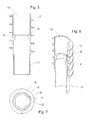
- FIG. 1 Assembled shown consists of a cylindrical receiving element 5, a (partially) frusto-conical receiving element 6, in its place also a (partially) conically downwardly tapered receiving element 6 can occur, and a receiving element as upper end element. 7
- the first-mentioned receiving elements 5, 6 have an external thread 2, is omitted in the upper end element 7 on the external thread 2.
- the sleeve-like receiving part for example, consist only of a plurality of cylindrical receiving elements 5. But it may also consist of several such elements and a (completely or partially) conical or frusto-conical shaped receiving element 6 or of such a and a receiving element as upper end element 7 Finally, it may consist of a (full or partial) cone or truncated cone-shaped receiving element. 6 and a receiving element as the upper end element 7 are formed.
- all elements can have an external thread 2.
- the receiving element as upper end element 7, corresponding elements without external thread belong, which can be used in a suitable case in the combination of elements, for example, between two elements with external thread.
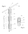
- the receiving elements 5, 6, 7 can be designed thick-walled or thin-walled self-supporting, in which case their adaptation to the Outside profile of the fitting core 4 of a Einschraubtechnikmaschinees 3 not only via a corresponding design of the wall of the receiving elements 5, 6, 7 directly, but also by the installation of correspondingly shaped ribs or passages 8 can be done, as shown in the FIGS. 5 to 9 is shown in more detail.
- the receiving elements 5, 6, 7 can also be so thin-walled that they can not easily transfer the forces and moments occurring when screwing. Then must - as in particular in the Figures 10 and 11 is shown in more detail - a dimensionally stable fitting core 4 of the system belonging screwing tool 3, to which they are plugged, be shaped so that it largely fills the receiving elements by positive fit and supports, so that they get their required for screwing into the soil dimensional stability and the forces and / or moments required for screwing in are transferred to it as uniformly as possible over a large area.
- the receiving elements 5, 6, 7 can be connected to each other, for example by training of tapered plug-in areas 11 and unused plug-in areas 12 plugged into each other and / or be locked together.
- a rotationally fixed connection for example, be generated in that the nestable receiving elements 5, 6, 7 - as shown in the drawings - have a polygonal cross-section.
- Such a connection may be useful when it is necessary to transfer forces from one to the other receiving element 5, 6, 7 or even to facilitate the handling of the multiple parts that are assembled into a receiving part 1.
- the receiving elements 5, 6, 7 can also be screwed into the ground without connection to one another, where they then inter alia by the external thread - Are anchored so that they no longer change their position even after removing the Einschraubwerkmaschinectiones 3.
- the internal cross-section of the receiving elements 5, 6, 7 must be designed to be continuously uniform in the axial direction.
- Only the conical or partially conical region of the conical or frusto-conical receiving element 6 allows, as this receiving element 6 is used only as a lower end - a different, for example conical design of the inner Cross-section and the corresponding part of the outer cross-section of the mating core 4.
- a corresponding - for example, conical - design of the outer contour of the mating core. 4 and the inner contour of the receiving element 6, as in FIG. 10 and 11 is shown.
- FIG. 2 shows the composition of receiving elements 5, 6, 7 after FIG. 1 in their to a sleeve-like receiving part 1 rotatable, push and pull together assembled form.
- FIG. 3 shows a cross section through the composition of receiving elements 5, 6, 7 according to FIG. 1 ,
- locking elements 9, 10 as locking grooves 9 and locking lugs 10 are better recognizable.
- the receiving elements 5, 6, 7 can be designed in their plug-in areas 11, 12 such that, when plugged together, a continuously uniform inner cross-section results in the axial direction.
- FIG. 4 shows a cross section through the mated receiving part 1 after FIG. 2 .
- each receiving element 5, 6, 7 of the fastening system corresponding passages 8 may also have a plurality of such passages 8.
- passages 8 define the free inner cross-section of the receiving elements 5, 6, 7, in which - so that the Aufsteckiana the receiving elements 5, 6, 7 is ensured on the passport core - nothing may protrude.
- FIG. 5 also shows the plug-in areas 11, 12 of the receiving element 5, here in the form of a (in the installation direction lower) cross-sectional taper 11 and an upper, unperforated cross-section 12.
- the upper, unperforated cross-section 12 of the or a receiving part 5, 6, 7 allows the insertion of the correspondingly tapered lower plug-in portion 11 of another receiving element 5, 7 and the lower, tapered plug portion 11 of the or a receiving element 5, 7 allows its insertion into the upper, unused plug portion 12 of the receiving elements 5, 6, 7th
- rejuvenated and unused plug-in area can also be interchanged.
- tapered plug-in portion 11 remains in its internal cross-section outside the cross section of the passages 8, so that the insertion of the passport core 4 by the receiving elements 5, 6, 7 or through the passages 8 is not hindered.
- FIG. 7 shows a cross section through the cylindrical receiving element 5 after FIGS. 5 and 6 in the region of its passage 8 with external thread 2, polygon-shaped passage 8, tapered plug-in area 11 and non-tapered plug-in area 12.
- FIG. 8 shows an inventive Einschraubtechnik Weg 3 with a fitting core 4 in the form of a hexagon, a handle 13 and with three plugged thereon, cut cylindrical receiving elements 5 with external thread 2, each having a polygonal passage 8 with a polygon of the fitting core 4 corresponding inner cross-section ,
- the receiving elements 5 can be seen their tapered plug-in areas 11 and their unused plug-in areas 12, but are unconnected plugged onto the mating core 4.
- FIG. 9 shows one of the cylindrical receiving elements FIG. 8 , partially cut, with external thread 2, polygon-shaped passage 8, tapered plug-in area 11 and non-tapered plug-in area 12.
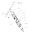
- FIG. 10 shows the composition of receiving elements 5, 6, 7 after FIG. 1 in the assembled to a receiving part 1 form according to FIG. 2 and the associated Einschraubtechnikmaschine 3 with fitting core 4 in a perspective view.
- the screw-in tool 3 has at its upper end an insertion opening 14 for a handle 13, a fitting core 4, which merges as an octagon with broken edges down into a conical shape 15.
- FIG. 11 shows the screw 3 after FIG. 10 with attached receiving part 1 after FIG. 10 in perspective and partially cut.
- the drill bit 16 the receiving part 1 orientaldingt and protrudes down therefrom as a drill bit.
- FIG. 12 shows a unit of Einschraubwerkmaschine 3 and mounted thereon receiving part 1 in a perspective view.
- the screw-3 is provided here with a handle 13.
- Its mating core 4 is formed as a hexagon.
- Receiving elements 5 attached on it are the cylindrical ones Receiving elements 5 attached.
- the screwing-in tool 3 penetrates the receiving elements 5 or the receiving part 1 formed from them and merges at its lower, near-earth end into a conical bore extension 17 with outer spiral.
Landscapes
- Engineering & Computer Science (AREA)
- Structural Engineering (AREA)
- Architecture (AREA)
- Civil Engineering (AREA)
- Mining & Mineral Resources (AREA)
- General Life Sciences & Earth Sciences (AREA)
- Life Sciences & Earth Sciences (AREA)
- Paleontology (AREA)
- General Engineering & Computer Science (AREA)
- Forms Removed On Construction Sites Or Auxiliary Members Thereof (AREA)
- Mutual Connection Of Rods And Tubes (AREA)
- Foundations (AREA)
- Piles And Underground Anchors (AREA)
Abstract
Description
Die Erfindung betrifft ein Befestigungssystem zum Befestigen eines stab- oder pfostenförmigen Gegenstandes im Erdboden mit einem in den Erdboden einzuschraubenden hülsenartigen Aufnahmeteil, das an seinem äußeren Umfang zumindest über einen Teil seiner Länge mit einem Außengewinde versehen ist und das im Befestigungszustand einen Endbereich des staboder pfostenförmigen Gegenstandes aufnimmt und dessen Umfang zumindest abschnittsweise umgibt, mit einem Einschraubwerkzeug, das einen formstabilen Passkern aufweist, auf den das Aufnahmeteil zum Zwecke des Einschraubens in das Erdreich drehfest aufsteckbar ist, gemäß dem Oberbegriff des Anspruchs 1.The invention relates to a fastening system for attaching a rod or post-shaped object in the ground with a screw-like receiving part to be screwed into the ground, which is provided at its outer periphery at least over part of its length with an external thread and in the attachment state, an end portion of the rod or post-shaped object receives and whose circumference surrounds at least in sections, with a screw-in, which has a dimensionally stable fitting core on which the receiving part for the purpose of screwing into the ground is rotatably attachable, according to the preamble of
Die Erfindung betrifft weiter ein entsprechendes Aufnahmeteil, das Einschraubwerkzeug, gegebenenfalls erforderliches Füllmaterial sowie entsprechende Befestigungsverfahren.The invention further relates to a corresponding receiving part, the screwing-in tool, optionally required filling material and corresponding fastening methods.
Ein derartiges Befestigungssystem zeigt beispielsweise die
Das Füllmaterial kann körnig sein, beispielsweise ein Granulat, ein harter Sand, Split- oder Gesteinsmaterial. Aber auch ein elastisches Kunststoffmaterial kommt in Frage, ebenso eine sich festigende flüssige Masse, vor allem Beton. Die Verwendung eines körnigen Materials hat den Vorteil, dass die gesamte Befestigungseinrichtung schnell wieder entfernt werden kann, z. B. bei vorübergehend erstellten Bauwerken auf Ausstellungen und Messen.The filler may be granular, such as granules, hard sand, split or rock material. But also an elastic plastic material comes into question, as well as a solidifying liquid mass, especially concrete. The use of a granular material has the advantage that the entire fastening device can be quickly removed again, for. For example, for temporary structures at exhibitions and fairs.
Das genannte, als Schraubhülse ausgeführten Befestigungssystem entspricht mit seinem becherförmigen Füllabschnitt im Aufnahmeteil in seiner Gestaltung weitgehend den ebenfalls bekannten Bodendübeln mit eigenem Aufnahmeabschnitt am oberen Ende, bei denen der stabförmige Gegenstand unmittelbar, ohne Zwischenlage eines Füllmaterials, in den Aufnahmeabschnitt eingesetzt und dort befestigt wird.Said, designed as a screw sleeve fastening system corresponds with its cup-shaped filling portion in the receiving part in its design largely the well-known ground dowels with own receiving section at the top, in which the rod-shaped object is used directly, without interposition of a filling material in the receiving portion and secured there.
Derartige Bodendübel sind in vielen Ausführungsformen bekannt; ein Beispiel zeigt die
Alle diese bekannten Bodendübel sind verhältnismäßig massiv ausgebildet. Sie müssen nämlich nicht nur die Kräfte aufnehmen, mit denen der Mast oder Pfosten sie beaufschlagt, wenn er unmittelbar an ihnen befestigt ist. Sie werden vor allem auch beim Eindrehen in den Erdboden stark belastet. Das gilt besonders dann, wenn ein von Hand oder maschinell betätigtes Eindrehwerkzeug an ihrem oberen Ende, beispielsweise mit einem quer durch den Aufnahmeabschnitt gesteckten Bolzen angreift, wie das oftmals vorgeschlagen wird (
Als Material für das Aufnahmeteil des bekannten Befestigungssystems wird daher beispielsweise Stahl, aus einem Stück gehämmert und feuerverzinkt, vorgeschlagen (Firmendruckschrift "Das neue Krinner Bodendübel-System" der Firma Krinner GmbH, D-94342 Straßkirchen), aber auch Kunststoff in großer Wandstärke oder - zumindest für Bodendübel - eine Kombination aus Kunststoff und Metall (
Alle diese Ausführungsarten sind deshalb für einen Massenartikel verhältnismäßig aufwendig, zumal sie zwar grundsätzlich wieder verwendbar wären, praktisch aber oftmals auch dann im Erdboden verbleiben, wenn der (nur vorübergehend erforderliche) Mast oder Pfosten wieder entfernt wird.All these embodiments are therefore relatively expensive for a mass-produced, especially since they would be basically reusable, but practically often remain in the ground when the (only temporarily required) mast or post is removed.
In Weiterentwicklung der eingangs genannten Befestigungssystems verzichtet deshalb die
Und zwar soll das Aufnahmeteil den eingestellten Pfosten nach der Lehre dieser Schrift mit Abstand umgeben, so dass zwischen dem stab- oder pfostenförmigen Gegenstand und der Innenkontur des Aufnahmeteils ein Ringraum entsteht, der mit einem Füllmaterial verfüllt wird, wodurch der Stab bzw. Pfosten fest im Boden verankert wird.And although the receiving part of the set post according to the teaching of this document surrounded by distance, so that between the rod or post-shaped object and the inner contour of the receiving part, an annular space is formed, which is filled with a filling material, whereby the rod or post fixed in Ground is anchored.
Die genannte Schrift schlägt weiter vor, das Eindrehwerkzeugs zum Eindrehen dieses Aufnahmeteils mit einem formstabilen Passkern zu versehen, der weitgehend oder vollständig an der Innenkontur des Aufnahmeteils anliegt und diese damit beim Eindrehen weitgehend ausfüllt und stützt und der so durch formschlüssige, insbesondere auch reibschlüssige Anpassung im Sinne des Eindrehens die zum Eindrehen erforderlichen Kräfte und/oder Momente möglichst großflächig auf das Aufnahmeteil überträgt und so dem lediglich als Schalung dienenden Aufnahmeteil erst seine zum Einbringen in den Erdboden erforderliche Formstabilität erteilt.The cited document also proposes to provide the insertion tool for screwing this receiving part with a dimensionally stable fitting core, which rests largely or completely on the inner contour of the receiving part and thus largely fills and supports during screwing and thus by positive, in particular frictional adjustment in the Sense of Eindrehens the forces required for screwing and / or torque over a large area on the receiving part and so the only serving as formwork receiving part granted only its required for introduction into the ground dimensional stability.
Vor allem diese letztgenannte Gestaltung hat es ermöglicht, das Aufnahmeteil entsprechend dünnwandiger und vor allem auch aus preiswerteren Materialien wie beispielsweise Kunststoffen herzustellen, wodurch erhebliche Kosten eingespart werden konnten.Above all, this latter design has made it possible to produce the receiving part according to thin-walled and especially from cheaper materials such as plastics, which could be saved considerable costs.
Dieser Stand der Technik baut auf der Erkenntnis auf, dass es (bei Verzicht auf die Möglichkeit, den Stab, Pfosten oder dgl. unmittelbar an dem Aufnahmeteil zu befestigen) bei entsprechender Auslegung des Eindrehwerkzeugs ausreicht, das hülsenartige Aufnahmeteil nach seiner Funktion als Schalung zu bemessen, auf die es reduziert ist, wenn es einmal in den Erdboden eingesetzt ist und das untere Ende des stabförmigen Teils über das Füllmaterial aufnimmt und hält.This prior art is based on the finding that it is sufficient (with the absence of the possibility of the rod, posts or the like. Directly on the receiving part) with appropriate design of the screwing tool to measure the sleeve-like receiving part according to its function as formwork to which it is reduced once it is inserted into the ground and receives and holds the lower end of the rod-shaped part over the filler material.
Das Aufnahmeteil dient dann nämlich nur noch nach Art einer Schalung dazu, das Füllmaterial zusammenzuhalten, sein diffundieren in das umliegende Erdreich und damit ein Lockern der Verankerung zu verhindern sowie ein verfestigendes Setzen des Füllmaterials zu unterstützen. Dabei stützt sich das Aufnahmeteil selbst in diesem Einbauzustand nach außen an dem sich verfestigenden Erdreich ab, das seinerseits das Aufnahmeteil auch nicht zusammendrücken kann, weil dessen Innenraum dann durch das Füllmaterial und das untere Ende des stabförmigen Teils ausgefüllt und ausgesteift ist.The receiving part then serves only in the form of a formwork to hold the filler together, to diffuse into the surrounding soil and thus to prevent loosening of the anchorage and to support a consolidating setting of the filling material. In this case, the receiving part is supported even in this installed state to the outside of the solidifying soil, which in turn can not compress the receiving part, because its interior is then filled and stiffened by the filling material and the lower end of the rod-shaped part.
Das beschriebene Befestigungssystem hat sich in der Praxis außerordentlich bewährt und wird dementsprechend umfangreich eingesetzt. Dabei ist deutlich geworden, dass eine gewisse Schwäche darin liegt, dass für die unterschiedlichen Anwendungen von leichten Fundamenteinrichtungen für Zäune, Verkehrszeichen usw. über Masten für Leitungen usw. bis hin zu Fundamenten für größere Bauwerke wie Hochspannungsmasten, Brücken usw. jeweils nach Durchmesser und Länge unterschiedlich dimensionierte Aufnahmeteile und entsprechend viele verschiedene Einschraubwerkzeuge hergestellt und vom Anwender vorgehalten werden müssen. Dies verursacht, was die verhältnismäßig teueren Einschraubwerkzeuge bzw. deren Passkerne angeht erhebliche zusätzliche Anschaffungskosten sowie dafür und für die Menge der vorzuhaltenden unterschiedlichen Aufnahmeteile einen entsprechend hohen Transport- und Lageraufwand.The fastening system described has proven extremely useful in practice and is therefore used extensively. It has become clear that a certain weakness lies in the fact that for the different applications of lightweight foundation equipment for fences, traffic signs, etc. on masts for cables, etc. up to foundations for larger structures such as pylons, bridges, etc. depending on the diameter and length differently sized receiving parts and correspondingly many different Einschraubwerkzeuge made and kept by the user , This causes, as regards the relatively expensive Einschraubwerkzeuge or their cores considerable additional cost and for this and for the amount to be kept different receiving parts a correspondingly high transport and storage costs.
Aufgabe der vorliegenden Erfindung ist es demgemäß, ein Befestigungssystem und die dazu gehörigen Einzelteile sowie ein Verfahren zur Verfügung zu stellen, das unnötige Kosten dadurch vermeidet, dass es mit einem oder einer geringen Zahl von Einschraubwerkzeugen oder Passkernen und wenigen unterschiedlichen Aufnahmeteilen ein möglichst breites Spektrum von Befestigungsmöglichkeiten abdeckt.Object of the present invention is therefore to provide a fastening system and the associated items as well as a method that avoids unnecessary costs that it with one or a small number of Einschraubwerkzeugen or passport cores and a few different receiving parts the widest possible range of Covering options.
Diese Aufgabe wird durch ein Befestigungssystem mit den Merkmalen gemäß Anspruch 1, durch ein Aufnahmeteil mit den Merkmalen gemäß Anspruch 17, durch ein Einschraubwerkzeug mit den Merkmalen gemäß Anspruch 18 und durch ein Verfahren mit den Merkmalen gemäß Anspruch 19 gelöst. Zweckmäßige Ausgestaltungen ergeben sich aus zugehörigen abhängigen Ansprüchen.This object is achieved by a fastening system having the features according to
Die Erfindung sieht die Lösung im modulartigen Aufbau des Befestigungssystems durch das Angebot einer Mehrzahl unterschiedlicher hülsenförmiger Aufnahmeelemente, von denen je nach den im Einzelfall gestellten Anforderungen eine geringere oder größere Zahl zu dem Aufnahmeteil der benötigten Dimensionierung (Länge) zusammengestellt werden kann.The invention provides the solution in the modular construction of the fastening system by offering a plurality of different sleeve-shaped receiving elements, of which a smaller or larger number can be put together to the receiving part of the required dimensioning (length) depending on the requirements made in the individual case.
Im einfachsten Falle wird es sich dabei um untereinander kombinierbare Aufnahmeelemente eines einzigen gleichen Querschnitts handeln, bei denen unterschiedliche Lastvorgaben nur durch Aneinanderreihung einer entsprechend größeren Zahl von Aufnahmeelementen und entsprechend längere Gestaltung des Aufnahmeteils Rechnung getragen werden kann. Für sehr unterschiedliche Lastvorgaben können aber auch Gruppen von jeweils miteinander kombinierbaren Halteelementen unterschiedlicher Querschnitte verfügbar gemacht werden.In the simplest case, these will be interchangeable receiving elements of a single same cross section, in which different load specifications only by juxtaposing a correspondingly larger number of receiving elements and correspondingly longer design of the receiving part can be taken into account. For very different load specifications but also groups of each combinable holding elements of different cross sections can be made available.
Der erfindungsgemäßen Gestaltung liegt die Erkenntnis zugrunde, dass der modulartige Aufbau eines solchen Befestigungssystems diesem einen breiteren Anwendungsbereich bei Einsparung von Lager- und Transportaufwand ermöglicht.The design according to the invention is based on the finding that the modular design of such a fastening system allows this a broader field of application while saving storage and transport costs.
Dabei macht es für die Erfindung keinen Unterschied, ob das Aufnahmeteil den Endbereich des darin eingestellten Stabes oder Pfostens - wie in
Für die Erfindung ist weiter von untergeordneter Bedeutung, ob die Aufnahmeelemente bzw. die aus ihnen gebildeten Aufnahmeteile dickwandig oder zwar dünnwandig aber gleichwohl selbsttragend stabil so ausgebildet sind, dass sie ohne einen sie haltenden und stützenden formstabilen Passkern eingedreht werden könnten oder ob sie eines Solchen, sie mehr oder weniger vollflächig stützenden Passkerns zum Eindrehen bedürfen, wie es in dem genannten Stand der Technik zu
Sie stellt freilich eine besonders vorteilhafte Ausführungsform des Gegenstandes der Erfindung dar, weil sie die Vorteile der Materialersparnis, die der Gegenstand der
Insoweit beruht die Erfindung auf der Erkenntnis, dass auch solche für sich allein wenig standfesten Aufnahmeelemente, wenn sie passgenau oder im wesentlichen passgenau auf einen gemeinsamen Passkern aufgesteckt und so in das Erdreich eingedreht werden, dabei in gleicher Weise gestützt und gehalten werden, wie ein einziges, zusammenhängendes Aufnahmeteil, sie also genauso materialsparend ausgelegt sein können wie ein größeres, zusammenhängendes Aufnahmeteil.In that regard, the invention is based on the finding that even those by itself less stable receiving elements, if they are fitted accurately or substantially accurately to a common mating core and screwed into the ground, thereby supported and held in the same way as a single , contiguous receiving part, so they can be designed just as material-saving as a larger, coherent receiving part.
Auch werden sie nach dem Entfernen des Einschraubwerkzeuges bzw. des stabilen Passkerns, dem Einstellen des Stabes oder Pfostens und dem Einfüllen des Füllmaterials in gleicher Weise im Erdreich und zwischen Erdreich und Stab/Pfosten bzw. Füllmaterial gehalten und gestützt wie ein einziges Aufnahmeteil.Also, after removing the screwing tool or the stable fitting core, adjusting the rod or post and filling the filling material, they are held in the same way in the soil and between soil and rod / post or filling material and supported like a single receiving part.
Sie verhindern auch in gleicher Weise wie ein einziges Aufnahmeteil das Diffundieren des Füllmaterials in das umliegende Erdreich und unterstützen das einer Lockerung des Halts des Stabes oder Pfostens entgegenwirkende Setzen, insbesondere eines rieselfähigen Füllmaterials wie Granulat, Split, Sand o.ä.They also prevent in the same way as a single receiving part, the diffusion of the filling material into the surrounding soil and support the relaxation of the holding of the rod or post counteracting setting, in particular a free-flowing filler material such as granules, split, sand, etc.
Für alles dies kommt es nicht einmal darauf an, dass die Aufnahmeelemente untereinander verbunden sind. Denn sie werden nach ihrem Einschrauben in das Erdreich, bei dem sie durch den Passkern in ihrer Stellung zueinander fixiert sind, nach dem Entfernen des Passkerns und dem Einstellen des Stabes oder Pfostens und Einfüllen des Füllmaterials in der einmal eingenommenen Position nachhaltig festgelegt.For all this it does not even matter that the receiving elements are connected to each other. Because they are after their screwing into the soil, in which they are fixed by the mating core in position to each other after the removal of the mating core and the setting of the rod or post and filling the filler in the once occupied position sustainable determined.
Deshalb werden auch für das Einstellen des Stabes oder Pfostens in das Aufnahmeteil selbst dann keine Probleme entstehen, wenn die Aufnahmeelemente ihn passgenau und ohne Füllmaterial halten sollen.Therefore, even for the adjustment of the rod or post in the receiving part, no problems arise even if the receiving elements should keep it accurately and without filler.
Dabei tragen naturgemäß, insbesondere wenn die Aufnahmeelemente unverbunden auf den Passkern aufgesteckt und so in das Erdreich eingeschraubt werden, die für das Einschrauben der Aufnahmeelemente erforderlichen Außengewinde zum Halt der Elemente im Verhältnis zueinander und im Erdreich wesentlich bei. Deshalb wird vorzugsweise jedes Aufnahmeelement mit einem Außengewinde ausgerüstet sein.In this case, of course, especially when the receiving elements unconnected plugged onto the mating core and screwed into the ground, the required for screwing the receiving elements external thread to hold the elements in relation to each other and in the soil significantly. Therefore, preferably, each receiving element will be equipped with an external thread.
Dies ist aber nicht zwangsläufig erforderlich. Wenn mehrere Aufnahmeelemente verwendet werden, kann bei Einzelnen, etwa einem zwischen zwei Aufnahmeelementen mit Gewinde platzierten Aufnahmeelement, auch auf ein Außengewinde verzichtet werden. Denkbar ist dies in gleicher Weise für ein Aufnahmeelement, das nur als oberes Abschlusselement zur Erdoberfläche hin vorgesehen ist, insbesondere wenn dieses mit dem benachbarten Aufnahmeelement verbunden ist.But this is not necessarily required. If several receiving elements are used, it can be dispensed with in individual, such as a placed between two receiving elements with threaded receiving element, even on an external thread. This is conceivable in the same way for a receiving element which is provided only as an upper closing element to the earth's surface, in particular when it is connected to the adjacent receiving element.
Der modulartige Aufbau des Aufnahmeteils kommt für alle bekannten Formen von Schraubfundamenten in Betracht, gleichgültig ob sie insgesamt zylinderförmig unten offen, zum unteren Ende hin kegelförmig spitz zulaufend oder kegelstumpfförmig mit unterer Öffnung gestaltet sind. Am einfachsten ist freilich die unten offene, zylindrische Form, da sie nur ein, nämlich ein zylindrisches hülsenartiges Aufnahmeelement erfordert, das in der nötigen Mehrzahl zu dem entsprechend dimensionierten Halteteil zusammengestellt werden kann.The modular design of the receiving part is suitable for all known forms of screw foundations, regardless of whether they are cylindrical open at the bottom, tapered towards the lower end tapered or truncated cone shaped with lower opening. Of course, the simplest is the downwardly open, cylindrical shape, since it requires only one, namely a cylindrical sleeve-like receiving element, which can be assembled in the necessary majority to the correspondingly sized holding part.
Das Aufnahmeteil kann aber auch aus mindestens einem hülsenartigen Aufnahmeelement zylindrischer Kontur und einem Aufnahmeelement mit in Einbaurichtung zumindest teilweise kegel- oder kegelstumpfförmig zulaufender Kontur mit Außengewinde bildbar sein, was voraussetzt, dass ein entsprechendes Modul vorgesehen ist.However, the receiving part can also be formed from at least one sleeve-like receiving element cylindrical contour and a receiving element with at least partially tapered or frusto-conical contour in the installation direction with external thread, which requires that a corresponding module is provided.
Weiterhin kann das Aufnahmeteil aus einem hülsenartigen Aufnahmeelement zylindrischer Kontur und/oder einem Aufnahmeelement kegel- oder kegelstumpfförmiger Kontur und einem Aufnahmeelement als oberem Abschlusselement mit oder ohne Außengewinde bildbar sein, was als weiteres Element ein entsprechendes Abschlusselement voraussetzt.Furthermore, the receiving part can be formed from a sleeve-like receiving element cylindrical contour and / or a receiving element cone or frusto-conical contour and a receiving element as the upper closing element with or without external thread, which requires a corresponding element as a further element.
Das erfindungsgemäße Befestigungssystem setzt also im einfachsten Falle ein einziges (zylindrisches) Aufnahmeelement voraus und bietet mit höchstens fünf verschiedenen Aufnahmeelementen (zylindrisches Aufnahmeelement mit und ohne Aussengewinde, spitz kegeliges, kegelstumpfförmiges Aufnahmeelement und oberes Abschlusselement) gleichen Querschnitts für einen weiten Bereich von Lastvorgaben ein breites Spektrum von Kombinationsmöglichkeiten.Thus, in the simplest case, the fastening system according to the invention requires a single (cylindrical) receiving element and, with a maximum of five different receiving elements (cylindrical receiving element with and without external thread, pointed conical, frustoconical receiving element and upper closing element) of the same cross section, offers a broad spectrum for a wide range of load specifications of possible combinations.
Wie bereits erwähnt, bedarf es, da die Aufnahmeelemente zum Eindrehen in das Erdreich auf den gemeinsamen Passkern aufgesteckt werden, und nach dem Eindrehen fest im Erdreich in ihrer Position verankert sind, an sich keiner Verbindung der Aufnahmeelemente untereinander. Jedoch ist auch eine drehfeste oder auch eine zug- und schubfeste Verbindung der Aufnahmeelemente untereinander, wenn erwünscht, mit einfachen Mitteln zu erreichen.As already mentioned, it is necessary, since the receiving elements are plugged for screwing into the soil on the common mating core, and are firmly anchored in their position after screwing in the ground, no connection of the receiving elements with each other. However, a non-rotatable or a tensile and shear-resistant connection of the receiving elements with each other, if desired, to achieve with simple means.
Die drehfeste Verbindung ergibt sich beispielsweise ohne Weiteres, wenn die Aufnahmeelemente im Formschluss, etwa im Querschnitt als Vieleck, ineinander steckbar ausgebildet sind.The non-rotatable connection results, for example, without further ado, when the receiving elements in the positive connection, approximately in cross-section as a polygon, are plugged into each other.
Die Zug- und schubfeste Verbindung kann in einfacher Weise durch Klipsverbindungen im Bereich der Steckverbindung realisiert werden.The tensile and shear-resistant connection can be realized in a simple manner by clip connections in the region of the connector.
Die drehfeste Aufsteckbarkeit der hülsenartigen Aufnahmeelemente auf den Passkerns kann in unterschiedlicher Art und Weise bewerkstelligt werden. Neben einem Reibschluss, der auch durch ein hydraulisches Aufdehnen des Passkerns erzeugt oder verstärkt werden kann, kommt insbesondere ein Formschluss in Betracht.The non-rotatable attachability of the sleeve-like receiving elements on the passport core can be accomplished in different ways. In addition to a frictional connection, which can also be generated or reinforced by a hydraulic expansion of the dowel core, in particular a form fit comes into consideration.
Beispielsweise können an die Innenseite der Aufnahmeelemente Rippen angeformt sein, die in Längsrichtung der Aufnahmeelemente verlaufen und in entsprechende Längsnuten des Passkerns eingreifen.For example, ribs may be formed on the inside of the receiving elements, which extend in the longitudinal direction of the receiving elements and engage in corresponding longitudinal grooves of the fitting core.
In Betracht kommen aber auch Durchlässe, die innen axial versetzt an die Aufnahmeelemente angeformt sind und in ihrem vieleckigen oder ähnlichen Innen-Querschnitt dem Außenquerschnitt des Passkerns entsprechen.But also come passages, which are formed axially offset on the receiving elements and in their polygonal or similar inner cross-section correspond to the outer cross section of the fitting core.
Diese beiden Varianten setzen allerdings voraus, dass die Aufnahmeelemente eine hinreichende Eigensteifigkeit haben, das heißt dass sie beim Einschrauben nicht der mehr oder weniger vollflächigen Stütze durch den Passkern bedürfen. Dann haben sie allerdings auch den Vorteil, dass durch entsprechende unterschiedliche Dimensionierung der Rippen bzw. Durchlässe unter Umstanden auch Aufnahmeteile/Aufnahmeelemente unterschiedlicher Dimensionierung (unterschiedlichen Außendurchmessers) mit ein- und demselben Einschraubwerkzeug betätigt werden können.However, these two variants assume that the receiving elements have a sufficient inherent rigidity, that is, that they do not require the more or less full-surface support through the fitting core when screwing. Then, however, they also have the advantage that by appropriate different dimensioning of the ribs or passages under certain circumstances also receiving parts / receiving elements of different dimensions (different outer diameter) can be operated with one and the same Einschraubwerkzeug.
Schließlich können die Aufnahmeelemente selbst einen zumindest innen vieleckigen oder einen ähnlichen Querschnitt aufweisen, der dem Außenquerschnitt des Passkerns entspricht. Diese Variante hat den Vorteil, dass der Passkern das entsprechend leicht gebaute Aufnahmeteil/Aufnahmeelement vollflächig stützen kann.Finally, the receiving elements themselves may have an at least inwardly polygonal or a similar cross section, which corresponds to the outer cross section of the fitting core. This variant has the advantage that the fitting core can support the correspondingly lightly constructed receiving part / receiving element over its entire surface.
Dabei versteht es sich, dass der für das Aufstecken der Aufnahmeelemente auf den Passkern in den Aufnahmeelementen erforderlichen Querschnitt frei sein muss, also insbesondere nicht in den durch die Rippen oder die Durchlässe definierten Querschnitt hineinragen darf.It is understood that the required for attaching the receiving elements on the fitting core in the receiving elements cross section must be free, so in particular may not protrude into the cross section defined by the ribs or the passages.
Wenn die Wand des Aufnahmeelements selbst den dem Außenquerschnitt des Passkerns entsprechenden Innenquerschnitt des Aufnahmeelements bildet, sollte - jedenfalls bei Aufnahmeelementen, die zum Einschrauben eine vollflächige Anlage des Passkern erfordern - diese vollflächige Anlage dadurch gewährleistet werden, dass die Aufnahmeteile - seien sie nun zusammengesteckt oder lose auf den Passkern aufgesteckt - über die gesamte Länge des gebildeten Aufnahmeteils (mit Ausnahme eines Bereichs spitz zulaufender Innenkontur in einem kegel- oder kegelstumpfförmigen Aufnahmeelement) einen im Wesentlichen stufenlos gleichbleibenden Innenquerschnitt aufweisen. Denn nur so kann sichergestellt werden, dass ein Einschraubwerkzeug mit einem formstabilen Passkern entsprechender Außenkontur ein Eindrehen der darauf aufgesteckten Aufnahmeteile in das Erdreich unter größtmöglicher gleichmäßiger Verteilung der dabei wirkenden Kräfte bewerkstelligen kann.If the wall of the receiving element itself forms the inner cross-section of the receiving element corresponding to the outer cross-section of the passport core, this full-surface contact should be ensured, at least in the case of receiving elements which require a full-surface installation of the dowel core for screwing in, that the receiving parts are now plugged together or loose mounted on the dowel core - over the entire length of the formed receiving part (with the exception of one area tapered inner contour in a cone or truncated cone-shaped receiving element) have a substantially continuous inner cross-section. This is the only way to ensure that a screwing-in tool with a dimensionally stable fitting core corresponding outer contour can bring in a screwing of the receiving parts placed thereon into the ground with the greatest possible uniform distribution of the forces acting thereon.
Dabei trägt die Ausnahme "eines Bereichs spitz zulaufender Innenkontur in einem kegel- oder kegelstumpfförmigen Aufnahmeelement" lediglich dem Umstand Rechnung, dass es im konischen Bereich naturgemäß an einem "stufenlos gleichbleibenden Querschnitt" fehlt. Im Interesse einer bestmöglichen Lastverteilung soll das Einschraubwerkzeug bzw. dessen Passkern selbstverständlich auch in diesem Bereich in seiner Außerkontur an die Innenkontur des kegel- oder kegelstumpfförmigen Aufnahmeelements so weit als möglich angepasst sein, so dass auch dieser Teil eines Aufnahmeelementes möglichst vollflächig mit dem Passkern in Kontakt gebracht werden kann, dem entgegenstehende Formgebungen also in jedem Falle zu vermeiden sind.The exception "an area of tapered inner contour in a conical or frusto-conical receiving element" merely takes into account the fact that, in the conical region, there is naturally no "continuously variable cross-section". In the interests of best possible load distribution, the screwing tool or its mating core should, of course, also be adapted as far as possible in its outer contour to the inner contour of the conical or frusto-conical receiving element in this area, so that this part of a receiving element as fully as possible with the mating core in contact can be brought, the opposing shapes are to be avoided in any case.
Für die einander entsprechende formschlüssige Auslegung von Aufnahmeelementen und Passkern kommen freilich auch andere als die zuvor beschriebenen Gestaltungen in Betracht. In jedem Falle muss bei ihnen aber gewährleistet sein, dass die Aufnahmeelemente in der gewünschten Art, Zahl und Reihenfolge auf den Passkern derart aufsteckbar sind, dass der Passkern jedes der Aufnahmeelemente durchgreift, sie koaxial ausgerichtet, drehfest, gegebenenfalls auch unter möglichst großflächiger Übertragung der beim Einschrauben auftretenden Kräfte, hält und dass der Passkern nach dem Einschrauben der Aufnahmeelemente auf einfache Art und Weise aus dem Schraubfundament zurückgezogen werden kann.For the corresponding positive interpretation of receiving elements and fitting core, of course, other than the previously described designs come into consideration. In any case, it must be ensured with them, however, that the receiving elements in the desired type, number and order on the fitting core are plugged so that the fitting core passes through each of the receiving elements, they coaxially aligned rotationally fixed, possibly even with the largest possible transmission of the Screwing forces occurring holds, and that the dowel core can be withdrawn after screwing the receiving elements in a simple manner from the screw foundation.
Hierfür ist von wesentlicher Bedeutung, dass die Außenkontur des formstabilen Passkerns des Einschraubwerkzeugs, wie immer sie im Einzelnen gestaltet sein mag, der Innenkontur der Aufnahmeelemente oder ihrer Durchlässe entspricht.For this purpose, it is essential that the outer contour of the dimensionally stable fitting core of the screw-in tool, whatever it may be designed in detail, corresponds to the inner contour of the receiving elements or their passages.
Die Kuppelung zwischen dem oder den hülsenartigen Aufnahmeelementen und dem Passkern kann dann beispielsweise auch in der Weise erfolgen, dass - wie in
Es versteht sich, dass das erfindungsgemäße Befestigungssystem seinen vollen Nutzen nur entfalten kann, wenn der formstabile Passkern eine Baulänge aufweist, die der Höchstzahl bzw. der Gesamtlänge der Höchstzahl der im praktischen Gebrauch zu einem Aufnahmeteil zusammenzufügenden Aufnahmeelemente entspricht.It is understood that the fastening system according to the invention can only develop its full benefits if the dimensionally stable fitting core has a length corresponding to the maximum number or the total length of the maximum number of receiving elements to be combined in a practical use to a receiving part.
Wenn dies gewährleistet ist, ist zugleich sichergestellt, dass die hülsenartigen Aufnahmeelemente nach ihrem - unverbundenen oder miteinander verbundenen - Aufstecken auf den Passkern zusammen mit diesem einen Einsetzkörper bilden, der das gemeinsame vollständige Einschrauben der Aufnahmeelemente in das Erdreich ermöglicht.If this is ensured, it is also ensured that the sleeve-like receiving elements after their - unconnected or interconnected - attaching to the fitting core together with this form an insert body, which allows the common complete screwing the receiving elements into the ground.
Ein dünnwandiges Aufnahmeelement ist bei seinem Einbringen in den Erdboden naturgemäß in dem Bereich seiner in den Erdboden eindringenden Spitze mechanisch am stärksten gefährdet. Deshalb kann weiter vorgesehen sein, dass die hülsenartigen Aufnahmeelemente bei eingesetztem Passkern zusammen mit diesem einen Einsetzkörper bilden, der in seiner dem Erdboden zugewandten Einbringrichtung in einem Kegel endet, der teilweise oder vollständig durch den die hülsenartigen Aufnahmeelemente in der Einbringrichtung durchgreifenden Passkern gebildet ist. Nach dem Einbringen des Einsetzkörpers in den Erdboden wird der Passkern wieder entfernt, so dass nur noch die als Schalung dienenden Aufnahmeelemente im Erdboden verbleiben.A thin-walled receiving element is naturally mechanically most endangered when it is introduced into the ground in the region of its penetrating into the ground tip. Therefore, it can further be provided that the sleeve-like receiving elements form an insert body with inserted fitting core together with this insert body which ends in its direction of the ground facing in a cone which is partially or completely formed by the sleeve-like receiving elements in the direction of insertion passport core. After insertion of the insert body in the ground of the fitting core is removed again, so that only serve as formwork receiving elements remain in the ground.
Der Passkern des Einbringwerkzeuges durchgreift somit das hohl ausgebildete hülsenartige Aufnahmeelement, bis er mit der Spitze seines Kegels nach unten aus dem in Einschraubrichtung unteren Aufnahmeelement herausragt. Der aus dem Passkern und den Aufnahmeelementen bestehende Einsetzkörper dringt mit der Spitze des Passkerns voran in den Erdboden ein. Da das Aufnahmeteil bzw. seine Elemente in der Regel ein nur einmal verwendbares Massenteil ist bzw. sind, das Einbringwerkzeug hingegen immer wieder verwendet werden kann, lohnt es sich, dieses Einbringwerkzeug aus einem widerstandsfähigen Werkstoff in hochwertiger Weise auszubilden, so dass es mit seiner Spitze viele Male als Eindringkörper in den Erdboden dienen kann.The dowel core of the insertion tool thus engages through the hollow sleeve-like receiving element until it projects with the tip of its cone down from the lower in the screw-in receiving element. The insert body consisting of the fitting core and the receiving elements penetrates into the ground with the tip of the fitting core first. Since the receiving part or its elements is usually a mass portion that can only be used once or are, however, the insertion tool can be used over and over again, it is worthwhile to form this insertion tool of a resistant material in high quality, so that it with its tip can serve many times as an indenter into the ground.
Alternativ ist auch eine Ausgestaltung möglich, bei der das in Einschraubrichtung untere hülsenartige Aufnahmeelement in seiner dem Erdboden zugewandten Einschraubrichtung in einem Kegel endet, dessen Spitzenbereich aus einem verstärkten Material besteht. Beispielsweise kann die geschlossene Spitze des hülsenartigen Aufnahmeelements aus einem anderen Kunststoff bestehen, als das übrige Aufnahmeelement, oder die Spitze kann durch ein Fasermaterial verstärkt sein. Sogar eine aus Metall bestehende Spitze an einem sonst aus Kunststoff bestehenden Aufnahmeelement ist denkbar. Da das hülsenartige Aufnahmeelement infolge seiner geringeren Stärke insgesamt in jedem Fall kostengünstiger wird, kann der hiermit verbundene etwas höhere Aufwand mehr als gerechtfertigt sein.Alternatively, a configuration is possible in which the lower sleeve-like receiving element in the direction of screwing in its direction of engagement facing the ground ends in a cone whose tip region consists of a reinforced material. For example, the closed tip of the sleeve-like receiving element may be made of a different plastic than the rest of the receiving element, or the tip may be reinforced by a fiber material. Even a tip made of metal on an otherwise plastic receiving element is conceivable. Since the sleeve-like receiving element due to its lower thickness in total is cheaper in any case, the associated with this somewhat more effort can be more than justified.
Im übrigen richten sich die für die Aufnahmeelemente und den Passkern des Einbringwerkzeugs in Frage kommenden Werkstoffe nach dem jeweiligen Anwendungsfall. Dabei muss neben der Belastung des aufgestellten staboder pfostenförmigen Gegenstandes auch die rechnerische Lebensdauer der Befestigung berücksichtigt werden. Bevorzugt besteht der Passkern des Einbringwerkzeugs aus einem metallenen Werkstoff, vorzugsweise aus Stahl, während für die hülsenartigen Aufnahmeelemente in jedem Fall ein Kunststoff in Frage kommt. Geeignete Kunststoffe sind beispielsweise Polyamide, Polypropylene, Polyethylene und Polystyrole, die in der hier aufgezählten Reihenfolge zugleich eine zunehmende Lebensdauer der Aufnahmeelemente im Erdboden bedeuten.Moreover, the materials suitable for the receiving elements and the fitting core of the insertion tool are based on the particular application. In addition to the load of erected rod or post-shaped object and the computational life of the attachment must be considered. Preferably, the fitting core of the insertion tool consists of a metal material, preferably of steel, while for the sleeve-like receiving elements in each case a plastic comes into question. Suitable plastics are, for example, polyamides, polypropylenes, polyethylenes and polystyrenes, which are listed in the here Sequence at the same time mean an increasing life of the receiving elements in the ground.
Soweit zu dem Befestigungssystem ein Füllmaterial gehört, kommen hierfür vor allem rieselfähige Materialien wie Sand, Split oder Bruchstein, aber auch Granulate beispielsweise aus Kunststoff in Betracht. Alternativ kann auch Beton verwendet werden.If a filling material is part of the fastening system, free-flowing materials, such as sand, split or quarry stone, but also granules, for example of plastic, are particularly suitable for this purpose. Alternatively, concrete can also be used.
Gegenstand der Erfindung ist zugleich das aus einer Mehrzahl von Aufnahmeelementen bildbare, in den Erdboden einschraubbare, hülsenartige Aufnahmeteil zum Befestigen eines stab- oder pfostenförmigen Gegenstandes im Erdboden sowie
das zugehörige Einschraubwerkzeug für ein solches Befestigungssystem und schließlich
das beim Einsatz des Befestigungssystems anzuwendende Befestigungsverfahren, das bei Aufnahmeelementen von hinreichender Eigensteifigkeit, die keines Füllmaterials bedürfen, durch die Verfahrensschritte gemäß Anspruch 19, ansonsten durch die Verfahrensschritte gemäß Anspruch 20 gekennzeichnet ist:The invention is also the formable from a plurality of receiving elements, screwed into the ground, sleeve-like receiving part for attaching a rod or post-shaped object in the ground and
the associated Einschraubwerkzeug for such a fastening system and finally
the fastening method to be used in the application of the fastening system, characterized in the case of mounting elements of sufficient inherent rigidity, which require no filling material, by the method steps according to claim 19, otherwise by the method steps according to claim 20:
Die Erfindung wird nun anhand von Ausführungsbeispielen näher erläutert:
-
Figur 1 -
Figur 2Zusammenstellung nach Figur 1 in zusammengesteckter Form als hülsenartiges Aufnahmeteil. -
Figur 3Aufnahmeelementen nach Figur 1 . -
Figur 4Aufnahmeteil nach Figur 2 . -
Figur 5 -
Figur 6Figur 5 in perspektivischer Darstellung. -
Figur 7Figur 5 und 6 im Bereich seines Durchlasses mit vieleckförmiger Innenkontur. -
Figur 8 -
Figur 9Figur 8 in perspektivischer Darstellung und teilweise geschnitten. -
Figur 10Zusammenstellung von Aufnahmeelementen nach Figur 1 in der zu einem Aufnahmeteil zusammengesteckten Form gemäßFigur 2 -
Figur 11Einschraubwerkzeug nach Figur 10 mit darauf aufgestecktem Aufnahmeteil nachFigur 10 perspektivisch und teilweise geschnitten. -
Figur 12
-
FIG. 1 shows a conceivable combination of several receiving elements (cylindrical and frusto-conical receiving element and receiving element as the upper closing element) with external thread for combination as a sleeve-like receiving part. -
FIG. 2 shows the compilationFIG. 1 in mated form as a sleeve-like receiving part. -
FIG. 3 shows a cross section through the collection of recording elementsFIG. 1 , -
FIG. 4 shows a cross section through the mated receiving partFIG. 2 , -
FIG. 5 shows a section through a cylindrical receiving element having a passage with vieleckförmiger inner contour for attachment to a mating core corresponding outer cross-section. -
FIG. 6 shows the cylindrical receptacle afterFIG. 5 in perspective view. -
FIG. 7 shows a cross section through the cylindrical receiving elementFIGS. 5 and 6 in the area of its passage with polygonal inner contour. -
FIG. 8 shows a screw-in tool in the form of a hexagon with three mounted thereon cylindrical, cut shown receiving elements, each with a passage with a hexagon of the screwing corresponding inner hexagon. -
FIG. 9 shows one of the recording elementsFIG. 8 in perspective and partially cut. -
FIG. 10 shows the composition of receivingelements FIG. 1 in the assembled to a receiving part form according toFIG. 2 and the associated Einschraubwerkzeug with fitting core in perspective view. -
FIG. 11 shows the screwing afterFIG. 10 with attached on the receiving part afterFIG. 10 in perspective and partially cut. -
FIG. 12 shows a unit from Einschraubwerkzeug and attached thereto receiving part in a perspective view.
Die in
Dabei verfügen die erstgenannten Aufnahmeelemente 5, 6 über ein Außengewinde 2, bei dem oberen Abschlusselement 7 ist auf das Außengewinde 2 verzichtet.In this case, the first-mentioned
Die Zusammenstellung kann jedoch auch ganz anders gewählt werden. So kann das hülsenartiges Aufnahmeteil 1 beispielsweise nur aus mehreren zylindrischen Aufnahmeelementen 5 bestehen. Es kann aber auch aus mehreren solchen Elementen und einem (ganz oder teilweise) kegel- oder kegelstumpfförmig ausgebildeten Aufnahmeelement 6 oder aus einem Solchen und einem Aufnahmeelement als oberen Abschlusselement 7 bestehen Schließlich kann es aus einem (ganz oder teilweise) kegel- oder kegelstumpfförmigen Aufnahmeelement 6 und einem Aufnahmeelement als oberen Abschlusselement 7 gebildet werden.However, the compilation can be chosen quite differently. Thus, the sleeve-
Dabei können alle Elemente ein Außengewinde 2 haben. Zu dem System können aber auch, wie hier beim Aufnahmeelement als oberen Abschlusselement 7 gezeigt, entsprechende Elemente ohne Außengewinde gehören, die im geeigneten Falle in der Kombination der Elemente, beispielsweise auch zwischen zwei Elementen mit Außengewinde, Verwendung finden können.In this case, all elements can have an
Die Aufnahmeelemente 5, 6, 7 können dickwandig oder auch dünnwandig selbsttragend ausgelegt sein, in welchem Falle ihre Anpassung an das Außenprofil des Passkerns 4 eines Einschraubwerkzeuges 3 nicht nur über eine entsprechende Gestaltung der Wandung der Aufnahmeelemente 5, 6, 7 unmittelbar, sondern auch durch den Einbau von entsprechend geformten Rippen oder Durchlässen 8 erfolgen kann, wie dies in den
Die Aufnahmeelemente 5, 6, 7 können aber auch so dünnwandig sein, dass sie die beim Einschrauben auftretenden Kräfte und Momente nicht ohne weiteres übertragen können. Dann muss - wie insbesondere in den
Dies kann, wenn ein entsprechender Reibschluss gewährleistet ist, schon bei einem runden Innenquerschnitt der Aufnahmeelemente 5, 6, 7 und einem entsprechenden Außenquerschnitt des Passkerns 4 gewährleistet sein. Vorzugsweise kommt hierfür aber ein (zumindest innerer) Vielkant - Querschnitt der Aufnahmeelemente 5, 6, 7 - wie er in
Die Aufnahmeelemente 5, 6, 7 können miteinander verbindbar, etwa durch Ausbildung von verjüngten Steckbereichen 11 und unverjüngten Steckbereichen 12 ineinander steckbar und/oder miteinander verrastbar sein.The receiving
Dabei kann eine drehfeste Verbindung beispielsweise dadurch erzeugt werden, dass die ineinander steckbaren Aufnahmeelemente 5, 6, 7 - wie in den Zeichnungen gezeigt - einen Vielkant- Querschnitt aufweisen.In this case, a rotationally fixed connection, for example, be generated in that the
Zusätzlich kann eine schub- und zugfeste Verbindung beispielsweise durch entsprechende Rastelemente (Rastnuten 9 und Rastnasen 10) hergestellt werden.In addition, a thrust and tensile connection, for example, by corresponding locking elements (locking
Eine solche Verbindung kann sinnvoll sein, wenn es erforderlich ist, Kräfte von einem zum anderen Aufnahmeelement 5, 6, 7 zu übertragen oder auch nur um die Handhabung der mehreren Teile, die zu einem Aufnahmeteil 1 zusammengestellt sind, zu erleichtern.Such a connection may be useful when it is necessary to transfer forces from one to the other receiving
Eine derartige Verbindung der Aufnahmeelemente 5, 6, 7 ist jedoch an sich entbehrlich, wenn sie - wie zuvor erläutert - derart form- oder reibschlüssig auf den Passkern 4 aufsteckbar sind, dass die für das Eindrehen in das Erdreich erforderlichen Kräfte in ausreichendem Maße unmittelbar auf jedes einzelne Aufnahmeelement 5, 6, 7 übertragen werden können.However, such a connection of the receiving
Wenn ein solcher Form- oder Kraftschluss zwischen Passkern 4 und Aufnahmeelementen 5, 6, 7 beim Einschrauben gewährleistet ist, können die Aufnahmeelemente 5, 6, 7 auch ohne Verbindung untereinander in das Erdreich eingeschraubt werden, wo sie dann - unter anderem durch die Außengewinde 2 - derart verankert sind, dass sie ihre Position auch nach Entfernen des Einschraubwerkzeuges 3 nicht mehr ändern.If such a positive or frictional connection between the
Wenn die Aufnahmeelemente 5, 6, 7 mit möglichst vollflächiger Anlage an dem Passkern 4 auf diesen aufsteckbar sein sollen, muss allerdings der Innen-Querschnitt der Aufnahmeelemente 5, 6, 7 in axialer Richtung stufenlos gleichförmig gestaltet sein. Dasselbe gilt für den Außen-Querschnitt des Passkerns 4. Lediglich der konische bzw. teilkonische Bereich des kegel- oder kegelstumpfförmigen Aufnahmeelements 6 erlaubt, da dieses Aufnahmeelement 6 nur als unteres End - Element zum Einsatz kommt, eine abweichende, beispielsweise kegelförmige Gestaltung des Innen-Querschnitts und des entsprechenden Teils des Außen-Querschnitts des Passkerns 4. Auch hier empfiehlt sich dann aber zur Herstellung einer möglichst weitgehend großflächigen Kraftübertragung eine einander entsprechende - beispielsweise kegelförmige - Gestaltung der Außenkontur des Passkerns 4 und der Innenkontur des Aufnahmeelements 6, wie sie in
Dabei sind insbesondere die Rastelemente 9, 10 als Rastnuten 9 und Rastnasen 10 besser erkennbar.In particular, the
Außerdem ist hier gut erkennbar, wie die Aufnahmeelemente 5, 6, 7 in ihren Steckbereichen 11, 12 so gestaltet werden können, dass sich beim Zusammenstecken ein in axialer Richtung stufenlos gleichförmiger Innen - Querschnitt ergibt.In addition, it is easily recognizable here how the receiving
Auch hier ist insbesondere die erfindungsgemäße Gestaltung der Steckbereiche 11 mit ihren Rastelementen 9, 10 in ihrer Verrastung gut erkennbar.Again, in particular the inventive design of the plug-in
Dabei versteht sich, dass die anderen Aufnahmeelemente 5, 6, 7 des Befestigungssystems entsprechende Durchlässe 8 vieleckförmiger Innenkontur zur Anpassung an einen Passkern entsprechenden Außenquerschnitts aufweisen sollten und dass jedes Aufnahmeelement 5, 6, 7 statt des einen auch mehrere derartige Durchlässe 8 aufweisen kann.It is understood that the other receiving
Ebenso versteht sich, dass die Durchlässe 8 den freien Innen - Querschnitt der Aufnahmeelemente 5, 6, 7 definieren, in den - damit die Aufsteckbarkeit der Aufnahmeelemente 5, 6, 7 auf den Passkern gewährleistet bleibt - nichts hineinragen darf.Likewise, it is understood that the
Selbstverständlich können verjüngter und unverjüngter Steckbereich auch gegeneinander vertauscht sein.Of course, rejuvenated and unused plug-in area can also be interchanged.
Dabei versteht es sich, dass der verjüngte Steckbereich 11 in seinem Innen-Querschnitt außerhalb des Querschnitts der Durchlässe 8 bleibt, damit das Durchstecken des Passkerns 4 durch die Aufnahmeelemente 5, 6, 7 bzw. durch die Durchlässe 8 nicht behindert wird.It is understood that the tapered plug-in
Die Aufnahmeelemente 5 lassen ihre verjüngten Steckbereiche 11 und ihre unverjüngten Steckbereiche 12 erkennen, sind jedoch unverbunden auf den Passkern 4 aufgesteckt.The receiving
- 11
- hülsenartiges Aufnahmeteilsleeve-like receiving part
- 22
- Außengewindeexternal thread
- 33
- Einschraubwerkzeugscrewing
- 44
- Formstabiler PasskernDimensionally stable fitting core
- 55
- Zylindrisches AufnahmeelementCylindrical receiving element
- 66
- Kegel- oder kegelstumpfförmiges AufnahmeelementConical or frusto-conical receiving element
- 77
- Aufnahmeelement als oberes AbschlusselementReceiving element as the upper closing element
- 88th
- Durchlässepassages
- 99
- Rastnutenlocking grooves
- 1010
- Rastnasenlocking lugs
- 1111
- Verjüngter SteckbereichRejuvenated mating area
- 1212
- Unverjüngter SteckbereichUnjuvenated mating area
- 1313
- Handhabe des EinschraubwerkzeugesHandle of Einschraubwerkzeuges
- 1414
-
Einstecköffnung für Handhabe 13Insertion opening for
handle 13 - 1515
-
Kegelform des Passkerns 4Cone shape of the
mating core 4 - 1616
- Bohrmeißeldrill bit
- 1717
- Kegelförmiger BohrfortsatzCone-shaped drill extension
Claims (20)
Applications Claiming Priority (1)
| Application Number | Priority Date | Filing Date | Title |
|---|---|---|---|
| DE200710027545 DE102007027545B4 (en) | 2007-06-15 | 2007-06-15 | System and method for fixing a rod or post-shaped object in the ground with screwed into the ground multipart receiving part |
Publications (3)
| Publication Number | Publication Date |
|---|---|
| EP2003270A2 true EP2003270A2 (en) | 2008-12-17 |
| EP2003270A3 EP2003270A3 (en) | 2014-01-22 |
| EP2003270B1 EP2003270B1 (en) | 2014-08-20 |
Family
ID=39745482
Family Applications (1)
| Application Number | Title | Priority Date | Filing Date |
|---|---|---|---|
| EP20080104331 Not-in-force EP2003270B1 (en) | 2007-06-15 | 2008-06-10 | System and method for fixing a rod-shaped or post-shaped object in the ground with multi-section holder part which can be screwed into the ground |
Country Status (2)
| Country | Link |
|---|---|
| EP (1) | EP2003270B1 (en) |
| DE (1) | DE102007027545B4 (en) |
Cited By (6)
| Publication number | Priority date | Publication date | Assignee | Title |
|---|---|---|---|---|
| NL2001768C2 (en) * | 2008-07-04 | 2010-01-05 | Halil Dalkiran | Screw pile for use as support post, has end zone comprising shaft with external thread, and reinforcing ribs arranged in area between shaft and screw pile, where pile is made from concrete, plastic or composite of wood and plastic |
| WO2012139149A1 (en) * | 2011-04-11 | 2012-10-18 | Smart Urban Pty Ltd | A post retainer, post retaining system and method for retaining a post at a variable depth |
| AT16568U1 (en) * | 2018-08-10 | 2019-11-15 | Purt Alexander | Ground anchor system |
| EP3581756A1 (en) * | 2018-06-11 | 2019-12-18 | HILTI Aktiengesellschaft | Drilling device |
| US20210353037A1 (en) * | 2020-05-15 | 2021-11-18 | Brome Bird Care Inc. | Molded screw |
| DE102021130720B3 (en) | 2021-11-24 | 2023-03-30 | Winkelmann Powertrain Components GmbH & Co. KG. | Method of making a screw foundation |
Families Citing this family (1)
| Publication number | Priority date | Publication date | Assignee | Title |
|---|---|---|---|---|
| DE102010043785B3 (en) * | 2010-11-11 | 2012-03-22 | Krinner Innovation Gmbh | Screw foundation for e.g. post, has helical screw with tapered intermediate portion that includes convex cladding region whose convexity radius is equal to diameter of upper cylindrical portion of screw |
Citations (5)
| Publication number | Priority date | Publication date | Assignee | Title |
|---|---|---|---|---|
| DE9313258U1 (en) | 1993-09-02 | 1994-03-24 | Krinner, Klaus, 94342 Straßkirchen | Fastening device for rods, posts, masts or the like. in the ground |
| DE20000183U1 (en) | 2000-01-05 | 2000-07-06 | Ehler, Ingo, 59320 Ennigerloh | Metal screw-in dowel with screw-on metal extension sleeve |
| DE19960854A1 (en) | 1999-05-21 | 2001-03-29 | Klaus Krinner | Fixture system and anchoring device for rod or post-shaped object projecting from ground involves anchoring section fixable to ground surface and object holding section |
| DE20220515U1 (en) | 2002-06-14 | 2003-10-09 | Krinner Innovation GmbH, 94342 Straßkirchen | Ground spike for post or mast has a conical plastic moulded screw tip topped by a metal support sleeve |
| DE102005023465B3 (en) | 2005-05-20 | 2007-01-18 | Krinner Innovation Gmbh | Driving tool to cut upright post hole in soil has vertical groove engaging with matching rib on surrounding sleeve |
Family Cites Families (10)
| Publication number | Priority date | Publication date | Assignee | Title |
|---|---|---|---|---|
| FR2378198A1 (en) * | 1977-01-20 | 1978-08-18 | Tardieu Andre | Self contained ground anchor screw - is self tapping and can carry posts, hooks or other attachments |
| GB9212936D0 (en) * | 1992-06-18 | 1992-07-29 | Elle Holdings Limited Van | Pile |
| DE10122789A1 (en) * | 2001-05-10 | 2002-11-28 | Gerhard Blome-Tillmann | Holder for e.g. fence posts has threaded section for screwing into ground and tubular holding section for post made basically of plastics but with metal sleeve fitting onto holding section to enclose same |
| DE10214083A1 (en) * | 2002-03-28 | 2003-10-16 | Krinner Innovation Gmbh | Mast erection via ground anchor uses radial flank projection round mast end piece to form screw clear of mast socket inwall to allow filler grain anchoring. |
| DE20304257U1 (en) * | 2003-03-17 | 2003-05-22 | Hsu, Shih Hao, Bi Tou Hsiang, Changhua | Ground anchor for e.g. posts, comprises tube with screw part and stabiliser cap attached to help drive anchor into ground |
| DE20312771U1 (en) * | 2003-08-19 | 2003-11-06 | Wüster, Heinrich, Ing., Imst, Tirol | Ground anchor for holding e.g. washing lines, sun umbrellas etc in the ground has an insertion sleeve with an upper part and a point |
| JP2005061134A (en) * | 2003-08-19 | 2005-03-10 | Traverse:Kk | Steel pipe pile |
| US7037045B2 (en) * | 2003-10-06 | 2006-05-02 | Jones Robert L | Modular tubular helical piering system |
| JP4498798B2 (en) * | 2004-03-30 | 2010-07-07 | 大和ハウス工業株式会社 | Elongated pile and pile driving structure and driving method using the same |
| JP2006207287A (en) * | 2005-01-28 | 2006-08-10 | Atsushi Nakaya | Spiral pile and pile driving method |
-
2007
- 2007-06-15 DE DE200710027545 patent/DE102007027545B4/en not_active Expired - Fee Related
-
2008
- 2008-06-10 EP EP20080104331 patent/EP2003270B1/en not_active Not-in-force
Patent Citations (5)
| Publication number | Priority date | Publication date | Assignee | Title |
|---|---|---|---|---|
| DE9313258U1 (en) | 1993-09-02 | 1994-03-24 | Krinner, Klaus, 94342 Straßkirchen | Fastening device for rods, posts, masts or the like. in the ground |
| DE19960854A1 (en) | 1999-05-21 | 2001-03-29 | Klaus Krinner | Fixture system and anchoring device for rod or post-shaped object projecting from ground involves anchoring section fixable to ground surface and object holding section |
| DE20000183U1 (en) | 2000-01-05 | 2000-07-06 | Ehler, Ingo, 59320 Ennigerloh | Metal screw-in dowel with screw-on metal extension sleeve |
| DE20220515U1 (en) | 2002-06-14 | 2003-10-09 | Krinner Innovation GmbH, 94342 Straßkirchen | Ground spike for post or mast has a conical plastic moulded screw tip topped by a metal support sleeve |
| DE102005023465B3 (en) | 2005-05-20 | 2007-01-18 | Krinner Innovation Gmbh | Driving tool to cut upright post hole in soil has vertical groove engaging with matching rib on surrounding sleeve |
Cited By (10)
| Publication number | Priority date | Publication date | Assignee | Title |
|---|---|---|---|---|
| NL2001768C2 (en) * | 2008-07-04 | 2010-01-05 | Halil Dalkiran | Screw pile for use as support post, has end zone comprising shaft with external thread, and reinforcing ribs arranged in area between shaft and screw pile, where pile is made from concrete, plastic or composite of wood and plastic |
| WO2012139149A1 (en) * | 2011-04-11 | 2012-10-18 | Smart Urban Pty Ltd | A post retainer, post retaining system and method for retaining a post at a variable depth |
| EP3581756A1 (en) * | 2018-06-11 | 2019-12-18 | HILTI Aktiengesellschaft | Drilling device |
| WO2019238411A1 (en) * | 2018-06-11 | 2019-12-19 | Hilti Aktiengesellschaft | Drilling device |
| US11525308B2 (en) | 2018-06-11 | 2022-12-13 | Hilti Aktiengesellschaft | Drilling device |
| AT16568U1 (en) * | 2018-08-10 | 2019-11-15 | Purt Alexander | Ground anchor system |
| US20210353037A1 (en) * | 2020-05-15 | 2021-11-18 | Brome Bird Care Inc. | Molded screw |
| US11930912B2 (en) * | 2020-05-15 | 2024-03-19 | Brome Bird Care Inc. | Molded screw |
| DE102021130720B3 (en) | 2021-11-24 | 2023-03-30 | Winkelmann Powertrain Components GmbH & Co. KG. | Method of making a screw foundation |
| WO2023094395A1 (en) | 2021-11-24 | 2023-06-01 | Winkelmann Powertrain Components Gmbh & Co. Kg | Method for producing a screw foundation |
Also Published As
| Publication number | Publication date |
|---|---|
| DE102007027545B4 (en) | 2014-07-03 |
| EP2003270A3 (en) | 2014-01-22 |
| EP2003270B1 (en) | 2014-08-20 |
| DE102007027545A1 (en) | 2008-12-24 |
Similar Documents
| Publication | Publication Date | Title |
|---|---|---|
| DE69837524T2 (en) | Method for producing an anchoring, anchoring part and tensioning element for this purpose | |
| EP2003270B1 (en) | System and method for fixing a rod-shaped or post-shaped object in the ground with multi-section holder part which can be screwed into the ground | |
| DE19923080A1 (en) | Wall anchor to reinforce or secure walls; has long anchor section for insertion in one or more masonry blocks with at least one abutment to brace anchor against opening and prevent withdrawal | |
| DE102007052321A1 (en) | Arrangement for securing object e.g. post or mast in ground plug, has spare filling space for granular material for aligning object | |
| DE202013102352U1 (en) | Mounting system with ground dowel and multifunctional insertion aid | |
| DE202008010913U1 (en) | Screw foundation system with hardenable filling compound | |
| WO2014170339A1 (en) | Closure stopper for through-holes in concrete objects | |
| DE69032252T2 (en) | ANCHORING AND FASTENING METHOD BY SIDE SUPPORTS DRIVED IN THE FLOOR | |
| DE102005023465B3 (en) | Driving tool to cut upright post hole in soil has vertical groove engaging with matching rib on surrounding sleeve | |
| DE102005045574A1 (en) | Screw foundation for a ground anchor, to be screwed into the ground, has a spiral at a conical section between two cylindrical sections | |
| DE202019100898U1 (en) | Wall dowel for a precast concrete element | |
| EP1724416A2 (en) | Foundation system for the securing of a rod or postlike item in the ground and socket type receiving part therefor | |
| EP2324172B1 (en) | Foundation system for aligning and fastening a rod-like object in the soil | |
| DE102008037937A1 (en) | Foundation system for aligning and fastening rod or pillar-shaped object in ground, has plastic-receptacle part anchored in ground, which receives end area of rod or pillar-shaped object | |
| DE10142399C2 (en) | Fastening device for a tubular rod and use of the fastening device for setting up flagpoles | |
| DE102021134573A1 (en) | Fastening element, in particular for solar panels | |
| DE202010007006U1 (en) | Modular signage device with a variable number of signpost flags | |
| EP1985770A2 (en) | Method for fixing building elements to concrete | |
| DE20118703U1 (en) | Device for anchoring a rod-shaped object in the ground | |
| EP0542692A1 (en) | Device for anchoring construction parts to the ground | |
| EP1975345A2 (en) | Foundation device for building elements to be anchored in the ground | |
| WO2024033024A1 (en) | Fastening element with insert element, in particular for solar panels | |
| DE10161426A1 (en) | Anchor for cable supports, at building, has base plate with anchor rods passing through into building, and nuts on rods holding base plate between them | |
| DE69500260T2 (en) | Device for immobilizing a smooth, elongated part in the hole of an element, applications of such a device and production method of a molded body containing this device | |
| DE202007015245U1 (en) | Arrangement for fixing an object |
Legal Events
| Date | Code | Title | Description |
|---|---|---|---|
| PUAI | Public reference made under article 153(3) epc to a published international application that has entered the european phase |
Free format text: ORIGINAL CODE: 0009012 |
|
| 17P | Request for examination filed |
Effective date: 20080610 |
|
| AK | Designated contracting states |
Kind code of ref document: A2 Designated state(s): AT BE BG CH CY CZ DE DK EE ES FI FR GB GR HR HU IE IS IT LI LT LU LV MC MT NL NO PL PT RO SE SI SK TR |
|
| AX | Request for extension of the european patent |
Extension state: AL BA MK RS |
|
| PUAL | Search report despatched |
Free format text: ORIGINAL CODE: 0009013 |
|
| AK | Designated contracting states |
Kind code of ref document: A3 Designated state(s): AT BE BG CH CY CZ DE DK EE ES FI FR GB GR HR HU IE IS IT LI LT LU LV MC MT NL NO PL PT RO SE SI SK TR |
|
| AX | Request for extension of the european patent |
Extension state: AL BA MK RS |
|
| RIC1 | Information provided on ipc code assigned before grant |
Ipc: E04H 12/22 20060101AFI20131217BHEP Ipc: E02D 5/80 20060101ALI20131217BHEP |
|
| GRAP | Despatch of communication of intention to grant a patent |
Free format text: ORIGINAL CODE: EPIDOSNIGR1 |
|
| RIC1 | Information provided on ipc code assigned before grant |
Ipc: E04H 12/22 20060101AFI20140331BHEP Ipc: E02D 5/80 20060101ALI20140331BHEP |
|
| INTG | Intention to grant announced |
Effective date: 20140422 |
|
| GRAS | Grant fee paid |
Free format text: ORIGINAL CODE: EPIDOSNIGR3 |
|
| GRAA | (expected) grant |
Free format text: ORIGINAL CODE: 0009210 |
|
| AK | Designated contracting states |
Kind code of ref document: B1 Designated state(s): AT BE BG CH CY CZ DE DK EE ES FI FR GB GR HR HU IE IS IT LI LT LU LV MC MT NL NO PL PT RO SE SI SK TR |
|
| REG | Reference to a national code |
Ref country code: GB Ref legal event code: FG4D Free format text: NOT ENGLISH |
|
| REG | Reference to a national code |
Ref country code: CH Ref legal event code: EP |
|
| REG | Reference to a national code |
Ref country code: AT Ref legal event code: REF Ref document number: 683573 Country of ref document: AT Kind code of ref document: T Effective date: 20140915 |
|
| AKX | Designation fees paid |
Designated state(s): AT BE BG CH CY CZ DE DK EE ES FI FR GB GR HR HU IE IS IT LI LT LU LV MC MT NL NO PL PT RO SE SI SK TR |
|
| REG | Reference to a national code |
Ref country code: IE Ref legal event code: FG4D Free format text: LANGUAGE OF EP DOCUMENT: GERMAN |
|
| REG | Reference to a national code |
Ref country code: DE Ref legal event code: R096 Ref document number: 502008012126 Country of ref document: DE Effective date: 20141002 |
|
| REG | Reference to a national code |
Ref country code: NL Ref legal event code: VDEP Effective date: 20140820 |
|
| REG | Reference to a national code |
Ref country code: LT Ref legal event code: MG4D |
|
| PG25 | Lapsed in a contracting state [announced via postgrant information from national office to epo] |
Ref country code: FI Free format text: LAPSE BECAUSE OF FAILURE TO SUBMIT A TRANSLATION OF THE DESCRIPTION OR TO PAY THE FEE WITHIN THE PRESCRIBED TIME-LIMIT Effective date: 20140820 Ref country code: PT Free format text: LAPSE BECAUSE OF FAILURE TO SUBMIT A TRANSLATION OF THE DESCRIPTION OR TO PAY THE FEE WITHIN THE PRESCRIBED TIME-LIMIT Effective date: 20141222 Ref country code: BG Free format text: LAPSE BECAUSE OF FAILURE TO SUBMIT A TRANSLATION OF THE DESCRIPTION OR TO PAY THE FEE WITHIN THE PRESCRIBED TIME-LIMIT Effective date: 20141120 Ref country code: ES Free format text: LAPSE BECAUSE OF FAILURE TO SUBMIT A TRANSLATION OF THE DESCRIPTION OR TO PAY THE FEE WITHIN THE PRESCRIBED TIME-LIMIT Effective date: 20140820 Ref country code: SE Free format text: LAPSE BECAUSE OF FAILURE TO SUBMIT A TRANSLATION OF THE DESCRIPTION OR TO PAY THE FEE WITHIN THE PRESCRIBED TIME-LIMIT Effective date: 20140820 Ref country code: LT Free format text: LAPSE BECAUSE OF FAILURE TO SUBMIT A TRANSLATION OF THE DESCRIPTION OR TO PAY THE FEE WITHIN THE PRESCRIBED TIME-LIMIT Effective date: 20140820 Ref country code: NO Free format text: LAPSE BECAUSE OF FAILURE TO SUBMIT A TRANSLATION OF THE DESCRIPTION OR TO PAY THE FEE WITHIN THE PRESCRIBED TIME-LIMIT Effective date: 20141120 |
|
| PG25 | Lapsed in a contracting state [announced via postgrant information from national office to epo] |
Ref country code: LV Free format text: LAPSE BECAUSE OF FAILURE TO SUBMIT A TRANSLATION OF THE DESCRIPTION OR TO PAY THE FEE WITHIN THE PRESCRIBED TIME-LIMIT Effective date: 20140820 Ref country code: HR Free format text: LAPSE BECAUSE OF FAILURE TO SUBMIT A TRANSLATION OF THE DESCRIPTION OR TO PAY THE FEE WITHIN THE PRESCRIBED TIME-LIMIT Effective date: 20140820 Ref country code: IS Free format text: LAPSE BECAUSE OF FAILURE TO SUBMIT A TRANSLATION OF THE DESCRIPTION OR TO PAY THE FEE WITHIN THE PRESCRIBED TIME-LIMIT Effective date: 20141220 |
|
| PG25 | Lapsed in a contracting state [announced via postgrant information from national office to epo] |
Ref country code: NL Free format text: LAPSE BECAUSE OF FAILURE TO SUBMIT A TRANSLATION OF THE DESCRIPTION OR TO PAY THE FEE WITHIN THE PRESCRIBED TIME-LIMIT Effective date: 20140820 |
|
| PG25 | Lapsed in a contracting state [announced via postgrant information from national office to epo] |
Ref country code: EE Free format text: LAPSE BECAUSE OF FAILURE TO SUBMIT A TRANSLATION OF THE DESCRIPTION OR TO PAY THE FEE WITHIN THE PRESCRIBED TIME-LIMIT Effective date: 20140820 Ref country code: RO Free format text: LAPSE BECAUSE OF FAILURE TO SUBMIT A TRANSLATION OF THE DESCRIPTION OR TO PAY THE FEE WITHIN THE PRESCRIBED TIME-LIMIT Effective date: 20140820 Ref country code: DK Free format text: LAPSE BECAUSE OF FAILURE TO SUBMIT A TRANSLATION OF THE DESCRIPTION OR TO PAY THE FEE WITHIN THE PRESCRIBED TIME-LIMIT Effective date: 20140820 Ref country code: CZ Free format text: LAPSE BECAUSE OF FAILURE TO SUBMIT A TRANSLATION OF THE DESCRIPTION OR TO PAY THE FEE WITHIN THE PRESCRIBED TIME-LIMIT Effective date: 20140820 Ref country code: SK Free format text: LAPSE BECAUSE OF FAILURE TO SUBMIT A TRANSLATION OF THE DESCRIPTION OR TO PAY THE FEE WITHIN THE PRESCRIBED TIME-LIMIT Effective date: 20140820 Ref country code: IT Free format text: LAPSE BECAUSE OF FAILURE TO SUBMIT A TRANSLATION OF THE DESCRIPTION OR TO PAY THE FEE WITHIN THE PRESCRIBED TIME-LIMIT Effective date: 20140820 |
|
| REG | Reference to a national code |
Ref country code: DE Ref legal event code: R097 Ref document number: 502008012126 Country of ref document: DE |
|
| PG25 | Lapsed in a contracting state [announced via postgrant information from national office to epo] |
Ref country code: PL Free format text: LAPSE BECAUSE OF FAILURE TO SUBMIT A TRANSLATION OF THE DESCRIPTION OR TO PAY THE FEE WITHIN THE PRESCRIBED TIME-LIMIT Effective date: 20140820 |
|
| PLBE | No opposition filed within time limit |
Free format text: ORIGINAL CODE: 0009261 |
|
| STAA | Information on the status of an ep patent application or granted ep patent |
Free format text: STATUS: NO OPPOSITION FILED WITHIN TIME LIMIT |
|
| 26N | No opposition filed |
Effective date: 20150521 |
|
| PG25 | Lapsed in a contracting state [announced via postgrant information from national office to epo] |
Ref country code: SI Free format text: LAPSE BECAUSE OF FAILURE TO SUBMIT A TRANSLATION OF THE DESCRIPTION OR TO PAY THE FEE WITHIN THE PRESCRIBED TIME-LIMIT Effective date: 20140820 |
|
| REG | Reference to a national code |
Ref country code: DE Ref legal event code: R119 Ref document number: 502008012126 Country of ref document: DE |
|
| PG25 | Lapsed in a contracting state [announced via postgrant information from national office to epo] |
Ref country code: MC Free format text: LAPSE BECAUSE OF FAILURE TO SUBMIT A TRANSLATION OF THE DESCRIPTION OR TO PAY THE FEE WITHIN THE PRESCRIBED TIME-LIMIT Effective date: 20140820 |
|
| REG | Reference to a national code |
Ref country code: CH Ref legal event code: PL |
|
| GBPC | Gb: european patent ceased through non-payment of renewal fee |
Effective date: 20150610 |
|
| PG25 | Lapsed in a contracting state [announced via postgrant information from national office to epo] |
Ref country code: LU Free format text: LAPSE BECAUSE OF FAILURE TO SUBMIT A TRANSLATION OF THE DESCRIPTION OR TO PAY THE FEE WITHIN THE PRESCRIBED TIME-LIMIT Effective date: 20150610 |
|
| REG | Reference to a national code |
Ref country code: IE Ref legal event code: MM4A |
|
| REG | Reference to a national code |
Ref country code: FR Ref legal event code: ST Effective date: 20160229 |
|
| PG25 | Lapsed in a contracting state [announced via postgrant information from national office to epo] |
Ref country code: DE Free format text: LAPSE BECAUSE OF NON-PAYMENT OF DUE FEES Effective date: 20160101 Ref country code: GB Free format text: LAPSE BECAUSE OF NON-PAYMENT OF DUE FEES Effective date: 20150610 Ref country code: CH Free format text: LAPSE BECAUSE OF NON-PAYMENT OF DUE FEES Effective date: 20150630 Ref country code: LI Free format text: LAPSE BECAUSE OF NON-PAYMENT OF DUE FEES Effective date: 20150630 Ref country code: IE Free format text: LAPSE BECAUSE OF NON-PAYMENT OF DUE FEES Effective date: 20150610 |
|
| PG25 | Lapsed in a contracting state [announced via postgrant information from national office to epo] |
Ref country code: FR Free format text: LAPSE BECAUSE OF NON-PAYMENT OF DUE FEES Effective date: 20150630 |
|
| REG | Reference to a national code |
Ref country code: AT Ref legal event code: MM01 Ref document number: 683573 Country of ref document: AT Kind code of ref document: T Effective date: 20150610 |
|
| PG25 | Lapsed in a contracting state [announced via postgrant information from national office to epo] |
Ref country code: AT Free format text: LAPSE BECAUSE OF NON-PAYMENT OF DUE FEES Effective date: 20150610 |
|
| PG25 | Lapsed in a contracting state [announced via postgrant information from national office to epo] |
Ref country code: MT Free format text: LAPSE BECAUSE OF FAILURE TO SUBMIT A TRANSLATION OF THE DESCRIPTION OR TO PAY THE FEE WITHIN THE PRESCRIBED TIME-LIMIT Effective date: 20140820 |
|
| PG25 | Lapsed in a contracting state [announced via postgrant information from national office to epo] |
Ref country code: HU Free format text: LAPSE BECAUSE OF FAILURE TO SUBMIT A TRANSLATION OF THE DESCRIPTION OR TO PAY THE FEE WITHIN THE PRESCRIBED TIME-LIMIT; INVALID AB INITIO Effective date: 20080610 |
|
| PG25 | Lapsed in a contracting state [announced via postgrant information from national office to epo] |
Ref country code: CY Free format text: LAPSE BECAUSE OF FAILURE TO SUBMIT A TRANSLATION OF THE DESCRIPTION OR TO PAY THE FEE WITHIN THE PRESCRIBED TIME-LIMIT Effective date: 20140820 Ref country code: GR Free format text: LAPSE BECAUSE OF FAILURE TO SUBMIT A TRANSLATION OF THE DESCRIPTION OR TO PAY THE FEE WITHIN THE PRESCRIBED TIME-LIMIT Effective date: 20140820 |
|
| PG25 | Lapsed in a contracting state [announced via postgrant information from national office to epo] |
Ref country code: BE Free format text: LAPSE BECAUSE OF NON-PAYMENT OF DUE FEES Effective date: 20150630 |
|
| PG25 | Lapsed in a contracting state [announced via postgrant information from national office to epo] |
Ref country code: TR Free format text: LAPSE BECAUSE OF FAILURE TO SUBMIT A TRANSLATION OF THE DESCRIPTION OR TO PAY THE FEE WITHIN THE PRESCRIBED TIME-LIMIT Effective date: 20140820 |