EP1975345A2 - Foundation device for building elements to be anchored in the ground - Google Patents
Foundation device for building elements to be anchored in the ground Download PDFInfo
- Publication number
- EP1975345A2 EP1975345A2 EP08153478A EP08153478A EP1975345A2 EP 1975345 A2 EP1975345 A2 EP 1975345A2 EP 08153478 A EP08153478 A EP 08153478A EP 08153478 A EP08153478 A EP 08153478A EP 1975345 A2 EP1975345 A2 EP 1975345A2
- Authority
- EP
- European Patent Office
- Prior art keywords
- anchoring
- foundation device
- screw
- soil
- screw foundation
- Prior art date
- Legal status (The legal status is an assumption and is not a legal conclusion. Google has not performed a legal analysis and makes no representation as to the accuracy of the status listed.)
- Withdrawn
Links
Images


Classifications
-
- E—FIXED CONSTRUCTIONS
- E04—BUILDING
- E04H—BUILDINGS OR LIKE STRUCTURES FOR PARTICULAR PURPOSES; SWIMMING OR SPLASH BATHS OR POOLS; MASTS; FENCING; TENTS OR CANOPIES, IN GENERAL
- E04H12/00—Towers; Masts or poles; Chimney stacks; Water-towers; Methods of erecting such structures
- E04H12/22—Sockets or holders for poles or posts
- E04H12/2207—Sockets or holders for poles or posts not used
- E04H12/2215—Sockets or holders for poles or posts not used driven into the ground
- E04H12/2223—Sockets or holders for poles or posts not used driven into the ground by screwing
-
- E—FIXED CONSTRUCTIONS
- E04—BUILDING
- E04H—BUILDINGS OR LIKE STRUCTURES FOR PARTICULAR PURPOSES; SWIMMING OR SPLASH BATHS OR POOLS; MASTS; FENCING; TENTS OR CANOPIES, IN GENERAL
- E04H12/00—Towers; Masts or poles; Chimney stacks; Water-towers; Methods of erecting such structures
- E04H12/22—Sockets or holders for poles or posts
- E04H12/2253—Mounting poles or posts to the holder
- E04H12/2269—Mounting poles or posts to the holder in a socket
Definitions
- the invention relates to synchronfundament adopted for anchoring in the ground components according to the preamble of claim 1 and synchronfundamentsysteme according to the preamble of claim 28.
- Foundation devices for anchoring components such as poles, posts for playground equipment, traffic signs, fences and similar lighter, but also for the founding of significantly heavier components to foundations for electricity pylons, bridge piers and the like, are known in varying degrees.
- the retaining or plug-in section can be molded into the anchoring section for insertion of the component or can be molded for insertion or attachment or for other attachment ,
- sleeve-shaped SSfundament that are pointed downwards as for example conical, tapered or frustoconical closed hollow body with the help of a screw provided at their screwed into the soil your firm hold in the receiving soil is improved by the fact that they penetrate into the Soil this displace.
- the helix provides additional support in the soil.
- Screw foundation devices which are designed sleeve-like open down, generally provide a good grip in the soil their sleeve shape but also brings with it certain weaknesses that adversely affect especially in foundation facilities for high loads. Although their lateral stability is usually good Even against a nightly twisting they are relatively well secured But since they have a substantially constant axial cross-section with relatively small cross-sectional area, they can - for soft ground or very high support weights - u A movement in the axial direction, in particular the sinking in the soil, oppose too little resistance likewise their resistance against upwardly directed forces, thus for example against the wanton tearing out from the ground, be insufficient.
- the present application provides a first solution for utilizing the clear width of the sleeve to give the foundation additional support in the ground, in particular to increase the cross-sectional area of the foundation to prevent sinking in the case of a large contact pressure ,
- this can be effected by providing a closure plug which, after anchoring the sleeve in the ground, can be inserted therethrough and pushed and / or non-rotatably anchored to its lower opening in the direction of the longitudinal axis is and closes this opening in the installed state.
- the cross-sectional area of the foundation device is thereby increased by the clear inner width of the sleeve, which brings a significant additional securing the ground sleeve against further penetration into the soil with it.
- the closure stopper is integrally formed with the sleeve and rotated after its screwing into the appropriate position, folded or placed in a similar manner in the sleeve opening and anchored there.
- the stopper becomes formed in a structurally simple manner as a separate part, which is anchored after screwing the sleeve through the sleeve insertable in the lower opening.
- the closure plug after installation at least in the direction of the longitudinal axis of the sleeve shear resistant to be connected to the sleeve to oppose by increasing the cross-sectional area of the foundation means their further sinking after their anchoring in the ground additional bearing surface.
- the closure stopper should preferably at the same time tensile strength and / or rotatably formed on the sleeve anchored to be able to oppose additional resistance to a subsequent rotation of the sleeve or its movement up out of the ground.
- the closure plug may be a simple plate which is suitably secured in the lower opening of the sleeve, such as screwed.
- a closure stopper in the form of an upwardly open pot with side walls and a bottom plate, in which the side walls are anchored as a sleeve-like extension of the bottom sleeve at its lower state in the installed state, while the bottom plate so the extended foundation device in the direction of installation closes below.
- Such a design facilitates the insertion of the closure plug in the bottom sleeve, especially since the side walls can then act as a guide in the sleeve but above all created by the cup-shaped design of the closure plug on the side walls of space for the placement of means for shear-resistant and / or tensile and / or non-rotatable anchoring of the closure plug in the ground.
- closure plug Since the closure plug is anchored in an appropriate manner to the bottom sleeve, he stabilizes them in addition, by extending them in the result down, by closing the clear width of the sleeve, the footprint of the foundation device as a whole increased and by the rotating lamellae further enlargement of the Contact surfaces to the soil causes, thereby additionally counteracting both any further sinking of the device as well as their wandering or tearing out of the ground.
- the lamellae when the closure plug with the foundation device in turn is rotatably connected, at the same time their non-rotatable mounting total and thus counteract a reverse rotational movement, which would bring a relaxation in the soil with it this applies all the more, as the lamellae in turn rotate radially and not helically, so that any rotation of the foundation means does not lead to any significant loosening of the plug in the soil, the plug does not follow in particular a screwing easily.
- the torsional strength of the foundation device already improved by the lamellae as such, ie by their friction in the soil
- This effect can by a suitable, a rotational movement of the closure plug in the ground further counteracting, the resistance-increasing shape of the slats or the side walls of the closure -Stopfens itself, for example, be improved by interruptions in the slats or by a friction-increasing surface design.
- the closure plug is in turn screwed or preferably hammered after the insertion or insertion of the sleeve. He can at the same time in the sleeve in their hauling or screwing penetrate soil displaced, thereby causing a further hardening of the soil around the lower portion of the ground socket and thus contribute to a further stabilization of the foundation device in the ground.
- the bottom plate may additionally comprise means for the non-rotatable anchoring of the closure plug in the ground. These may for example consist in a cross-shaped extension of the bottom plate down.
- the bottom plate is formed with a downwardly facing in the direction of installation cone or truncated cone-shaped extension, which causes a lateral displacement of the soil and thus its solidification straight in the lateral direction.
- the bottom plate can also have a direction of installation substantially conical or frustoconical extension with means for rotationally fixed anchoring of the closure plug in the ground.
- the surface design may have the form of elevations or depressions. It also has a combination of surveys and depressions into account surveys have the disadvantage that they complicate the screwing but they have the advantage that they unfold their full anti-rotation effect immediately depressions have the advantage that they do not inhibit screwing Disadvantage, that they also unfold their full anti-twisting effect only gradually as the soil and, above all, the fouling (roots) are embedded in them.
- the elevations and / or depressions can be configured, for example, as tooth-like knurls running in the circumferential direction of the sleeve, possibly also the helical coil. However, they can also be designed, for example, as scales running in the circumferential direction.
- the scales will be counteracting the unscrewing They then stand, even if they protrude from the surface, the screwing of the foundation device barely.
- the anti-twist device should be designed to be particularly effective if the scales are undercut, because then there root system and the like can anchor very well.
- the surface design can be continued into the area of the foundation device into which the This would be in a foundation device in which the component is plugged, the remote part of the outer shell of the foundation device If the insertion of the component into the sleeve of the foundation device comes into consideration, could also its inner surface to secure a tight clamping fit be designed according to the component to be anchored.
- a fferably a sleeve-like body having an anchoring of a component in the ground serving anchoring portion and the component receiving holding or plug portion
- the anchoring portion as a displacement body formed with at least one conical region and at least over a part its upper part is provided with a helical screw for screwing into the soil, on the anchoring section above its conical area an upper part is formed, which in at least one cutting plane running through its longitudinal axis, at least outside, at least one zone of larger diameter than the diameter of the region acting as a clearing area Base of the conical region (which is the circular base of the cone), so that when screwing the foundation means by displacement of the soil in the region between the at least one zone of larger diameter and between the soil and the wall of the upper part at least one fillable gap is formed, can be reliably secured by the backfilling of the anchoring portion against subsequent rotation.
- This embodiment is preferred over a hereinafter also claimed embodiment in which the cross section of the upper part of the anchoring portion has smaller dimensions than the (circular) cross section of the base of the conical region, for example because the upper part is polygonal in cross-section and the corners of the polygon In cross-section do not protrude beyond the diameter of the base of the conical area In such a form, when screwing into the soil, although one or more gaps between the soil and upper part also form .
- the upper part of the anchoring section preferably has at least one zone of larger diameter than the diameter of the (circular) base of the conical section.
- the zone of larger diameter may be a bulge in the simplest embodiment over the length of a substantially cylindrical extension of the (circular) cone base of the conical region, which when driving the foundation device by displacing the soil an almost all-round fillable gap between the upper part of the anchoring portion and forms the soil.
- the upper part of the anchoring section will preferably have two or more zones of larger diameter distributed uniformly over its circumference. It will preferably be formed as a polygon, in which at least one of the edges, but preferably all edges lie in a zone of larger diameter.
- the polygon can, for example, have two opposite edges or be formed in cross-section triangular, rectangular, square or with a different number of edges Er can then form a corresponding plurality of fillable columns when screwing.
- the sides of the polygon can be deformed inwards.
- At least one of the edges of the polygon can be sawtooth-deformed, preferably in counter to the insertion direction directed toothing.
- this holding or plugging portion can in the simplest case on the anchoring portion itself, but here - because the anchoring portion is completely submerged in use in the ground - only as an inner contour for insertion of the component (rod, post, masts or the like.) Be formed in the upper part of the anchoring portion.
- a holding or plugging section can also be provided integrally connected to the upper part of the anchoring portion or connectable holding part, which - if it is designed as a separate component - can also be plugged into a correspondingly shaped receptacle of the upper part, screwed o
- the holding part can then in turn have a receptacle as an inner contour for insertion or as an outer contour for attaching the component.
- the receptacle can be designed as an inner contour in its cross section, in particular the cross section of the outer contour, that is not only round, but also as polygonal (triangular, square, etc) for receiving a component with a corresponding cross section.
- special designs of the wall such as a deformation the sides of the polygon inside at the same time as storage means, for example, as a clamping means for the component to be stored can be used.
- the cross-section of the upper part of the anchoring portion has at most the same maximum maximum dimensions as the (circular) cross-section of the base of the conical region, whereby recesses cause corresponding gaps between soil and upper part when screwed in.
- These foundation devices also have a sleeve-like body on, which in turn has an anchorage in the ground serving anchoring portion and a component receiving holding or plug-in portion.
- the anchoring portion is designed as a displacement body with at least one conical region with a circular cross-section and is provided at least over part of its length with a thread for screwing into the soil.
- an upper part is formed on the anchoring section above the conical region, whose cross-section has at least two separate regions, which are retracted relative to the circular cross-section of the base of the conical region in the direction of the longitudinal axis.
- This causes the soil during the screwing of the foundation device is displaced by the conical region and thereby at least one fillable gap between the soil and the wall of the shell is formed at the retracted areas By filling these gaps, the anchoring portion is reliably secured against subsequent rotation.
- the term drawn-in region should be understood to mean that, unlike the circular cross-section of the base of the conical region, ie the circular envelope, only certain regions in the form of noses, corners or protruding cam-like shapes are formed there, the remaining region, however, with respect to FIG Circular envelope is retracted, that is offset inward in the direction of the longitudinal axis, so that virtually one or more cavities arise in the ground.
- a single nose on one side of the cross section may extend to the circular envelope, which is surrounded on both sides with retracted areas, which of course do not necessarily have to extend over half of the circumference, but for example, only over about a quarter of the circumference.
- an asymmetrical profile would indeed arise, but such a profile could be important, for example, if, on the one hand, an anti-rotation device is used If, on the other hand, for example, wind pressure is to be absorbed on a device fastened in the fastening device of primarily one side.
- the invention further relates to a foundation system for fastening components, in particular of rods, posts, masts or the like in the ground, consisting of an anchorage in the ground serving foundation device according to claims 17 to 27 and a filler for filling the screwing in the foundation device resulting fillable columns.
- the filling material used depends on the type of pending substrate, the static requirements for the device, its dimensioning and the nature of the material. Suitable filling materials are, in particular, concrete or granular materials of uniform or different grain size, in particular sand or split, optionally with addition can be used by the PH value changing substances.
- concrete as a more elaborate filling material with a suitable substrate ensures a particularly secure anchoring.
- sufficient split is recommended, especially for medium requirements, because it is inexpensive, easy to access and easy to handle and by its good flowability a simple post consolidation of the environment Due to its structure, it creates, in particular in connection with the shaping of the anchoring section, by wedging a very good protection against undesired subsequent twisting, in particular a reverse rotation of the screwed device He also contributes to the corrosion protection of the foundation device, because he the PH value in the environment of the device in the soil favorably influenced, so that in itself possible additions to the PH value changing substances to the filler are usually unnecessary.
- FIG. 1 shows a foundation device 1 according to the invention, consisting on the one hand of a sleeve 2 open on both sides circular cross-section as a screw with rotating helical and on the other hand of a cup-shaped closure plug 3, which is locked with its side wall 6 in the form of a sleeve-like extension of the sleeve 2 with this and elastic deformable circumferential lamellae 8 has.
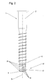
- FIG. 2 shows a foundation device 1 according to the invention, the device according to FIG. 1 is similar, but in which the threaded sleeve has a partially conical cross-section and which are formed on the closure plug 3 encircling, elastically deformable blades 8 interrupted.
- FIG. 3 shows a detail of a foundation device 1 according to the invention, consisting of a screw shown in its lower end 2 with indicated helical coil 14 and in the lower opening 4 by means of deformable Lammellen 8 guided pot-shaped closure plug 3 with side wall 6 with further elastically deformable blades 8 and a Bottom plate 7.
- FIG. 4 shows a detail of a foundation device 1 according to the invention, consisting of a sleeve 2 shown in its lower end with latched in the lower opening 4 of the sleeve 2 pot-shaped closure plug 3 with side wall 6 and radially thereabout elastically deformable fins 8 and bottom plate. 7
- FIG. 5a shows a cup-shaped closure plug 3 with side wall 6, radially surrounding elastically deformable blades 8 and bottom plate 7 in a perspective view.
- FIG. 5b shows the pot-shaped closure plug 3 after FIG. 5a in section
- FIG. 6a shows a cup-shaped closure plug 3 with side wall 6 with circumferential elastic lamellae 8 and bottom plate 7 and with a latching device for locking the closure plug 3 with the sleeve 2 in a perspective view.
- FIG. 6b shows the pot-shaped closure plug 3 after FIG. 6a in section.
- Figure 7a shows a cup-shaped closure plug 3 with side wall 6 with circumferential, but interrupted elastic blades 8 and bottom 7 and with a latching device for locking the closure plug 3 with the sleeve 2 in a perspective view
- FIG. 7b shows the pot-shaped closure plug 3 after Figure 7a in section.
- FIG. 8 shows a detail of a foundation device 1 according to the invention, consisting of a bottom sleeve 2 shown in its lower end as Einschraubhülse with rotating helix and end anchored cup-shaped closure plug 3 with side wall 6, elastically deformable blades 8 and bottom plate 7 with a cruciform or frustoconical cone-shaped extension 10, 11.
- FIG. 9a shows the pot-shaped closure plug 3 after FIG. 8 with means for non-rotatable anchoring to the ground socket.
- FIG. 9b shows the screw-in sleeve FIG. 8 with means for non-rotatable anchoring of the closure plug.
- FIG. 10a shows a foundation device 1 as a conical, bottom closed ringfundament 13 with helical coil 14 and a surface design in the form of a circumferential tooth-like knurling 15th
- FIG. 10b shows an enlarged section through the tooth-like knurling 15 according to FIG. 10a
- FIG. 11 shows a foundation device 1 as a cone-shaped screw foundation 13 with helical coil 14 and a surface configuration in the form of circumferentially extending scales 16th
- FIG. 12a shows a foundation device 1 as a top and bottom open SSfundament 13 with a surface configuration in the form of circumferentially extending scales 16th
- FIG. 12b shows a section through the screw foundation 13 after FIG. 12a on the line A / A
- FIG. 12c shows an enlarged detail of the section FIG. 12b .
- FIG. 13a shows a foundation device 1 as above and below open SSfundament 13 with helical coil 14 and a surface configuration in the form of circumferentially extending, undercut scales 17th
- FIG. 13b shows a section through the screw foundation 13 after FIG. 13a on the line B / B.
- FIG. 13c shows an enlarged detail of the section FIG. 13b .
- FIG. 14 shows the spatial, partially cutaway view of a foundation device 1 according to the invention after its screwing into the soil 21.
- the foundation device in the form of a sleeve-like body 2 consists of a designed as a displacement body anchoring portion 18 and a holding or plugging portion 19 of the anchoring portion 18 has a conical region 20 with helical screw 14 for screwing into the soil 21, a transition region 29 between the conical portion 20 and upper part 22 and an upper part 22 of the anchoring portion 18 and a molded or attached or plugged this holding part 19, 32 with a receptacle 34.
- Part 19, 32 shown above part can also be interpreted as inserted in a receptacle 34 of the anchoring portion 18 rod, mast, posts or the like.
- the upper part 22 of the anchoring section 18, which is arranged above the conical region 20, has, as the holding part 19, 32 attached to it, a square cross-section, therefore, as also shown on the holding part 19, 32, in at least one, in fact but in two extending through its longitudinal axis 5 cutting planes 23, namely in the diagonal, zones larger diameter 24 than the diameter 25 of the base of the conical portion 20
- By screwing the anchoring portion 18 in the soil 21 are in the range of - here in cross section square -
- Upper part 22 of the anchoring portion 18 produced by displacement generated fillable gaps 26, which are filled with filler 30.
- FIGS. 15 a - f show spatial representations of various anchoring sections 18 according to the invention.
- FIG. 15 Figure a shows an anchoring portion 18 with upper portion 22 of anchoring portion 18 disposed above the conical portion 20 provided with helical coil 14 as a double edge and with a section plane 23 passing through a longitudinal axis 5 and the two edges forming a zone 24 of larger diameter than the diameter 25 of the base of the conical region 20 forms
- FIG. 15b shows an anchoring portion 18 with above the screw head 14 equipped with conical portion 20 arranged upper part 22 of the anchoring portion 18 in the form of a cylinder-like tube with four edges 27 a - d (see also FIG. 16d ), Saw-tooth-like formations in cross-section and with a cutting plane 23 extending through a longitudinal axis 5 defining one of two zones (formed by the two diagonals through the saw-toothed formations) of larger diameter 24 than the diameter 25 of the base of the conical zone 20 and a transitional zone 29 between conical portion 20 and upper part 22 of the anchoring portion 18th
- FIG. 15c shows an anchoring portion 18 with above the screw head 14 equipped with conical portion 20 arranged upper part 22 of the anchoring portion 18 as a square 27 a - d (see also FIG. 16b ) with inwardly deformed sides of the square and with a cutting plane 23 passing through a longitudinal axis 5 of the anchoring section 18 defining one of two zones (formed by the two diagonals) of larger diameter 24 than the diameter 25 of the base of the conical zone 20, and a transition region 29 between conical region 20 and upper part 22 of the anchoring section 18
- FIG. 15d shows a similar design, but without inwardly deformed sides of the square.
- FIG. 15e shows an anchoring portion 18 with above the screw head 14 equipped with conical portion 20 arranged upper part 22 of the anchoring portion 18 as a square 27 a - d (see FIG. 16b ) and with a cutting plane 23 extending through a longitudinal axis 5 defining one of two zones (formed by the two diagonals) of larger diameter 24 than the diameter of the base 25 of the conical zone 20 and a transition zone 29 between the conical zone 20 and the upper part 22 the anchoring portion 18.
- the helical coil 14 extends here into the transition region 29 between the conical region 20 and top 22 of the anchoring portion 18th
- FIG. 15f shows an anchoring portion 18 similar to that FIG. 15a in which the threads of the helical spiral 14 extend up into the transition region 29.
- FIG. 16 a - e show different cross sections through different upper parts 22 of anchoring sections 18, each with the circular indication of the envelope 33, which at the same time indicates the state of the displaced earth 21 in the region of the upper part 22 of the anchoring section 18 after screwing in the anchoring section 18.
- FIG. 16 a shows the state after screwing in an anchoring section 18 with a triangular upper part 22 of the anchoring section 18 with edge regions 27 a, b, longitudinal axis 5 and through them and by edges 27a and 27b extending, a zone 24 of larger diameter forming cutting plane 23 Shown are also formed by screwing the anchoring portion 18 in the region of its upper part 22 filler column 26th
- FIG. 16b shows the state after screwing in an anchoring portion 18 with square top 22 with edge portions 27 a - d, longitudinal axis 5 and through them and two edges 27 a and 27 c and 27 b and 27 d extending, two zones 24 of larger diameter forming cutting planes 23. Also shown are the fillable gaps 26 formed by screwing in the region of the upper part 22 of the anchoring section 18 and the filler material 30 shown here in only one gap segment.
- the representation here is chosen to be axisymmetric, so that all four edges to the same extent Ground 21 displace when screwing in the anchoring portion 18 and the same round, by the dimensions of the upper part 22 from each other largely separate fillable gaps 26 arise. It is understood that - if desired - by appropriate displacement of the longitudinal axis 5 of the anchoring part 18, the number of displacing acting edges 27 can be reduced to two or even one.
- FIG. 16c shows much the same as FIG. 16b However, the side walls of the polygon 27 are here - similar to in FIG. 15c shown - deformed inwards.
- FIG. 16d shows the state after screwing the anchoring portion 18 with upper part 22 according to FIG. 15b with sawtooth edge portions 27 a - d, longitudinal axis 5 and through them and two sawtooth edges 27 a and 27 c and 27 b and 27 d extending, two zones 24 of larger diameter forming cutting planes 23 are shown by the screwing in the area Upper part 22 of the anchoring section 18 formed fillable column 26, the representation here is also chosen axisymmetric, so that all four edges 27 a - d displace the soil 21 to the same extent and all around, by the dimensions of the upper part 22 from each other largely separate fillable gaps 26 arise , It is understood that - if desired - by appropriate displacement of the longitudinal axis 5, the number of displacing acting edges 27 can be reduced to two or even one.
- FIG. 16e finally shows the state after screwing in an anchoring portion 18 with two-edge upper part 22 according to FIG. 15a in which the helical coil 14 is guided into the upper part 22 and in the threads of the helical coils in the region of the upper part 22 - in the region in which fillable gaps 26 are formed when screwing in - passage openings 31 for the filling material 30 are formed.
- FIG. 17 shows a foundation device 1 according to a second embodiment of the invention.
- the fundamen worn according to this embodiment has analogously to FIG. 16e a triangle with a nose-like tip 27 a and another 27 b on.
- the maximum diameter of this cross-sectional profile is equal to the diameter 25, which characterizes the circular cross-section of the base of the conical displacement body This characterized by the diameter 25 maximum diameter of the displacement section encloses the Zweieckform 27 a, 27 b and leaves with respect to the envelopes the retracted areas 35, 36.
- the two retracted areas 35, 36 are separated.
- the cross section of an embodiment according to FIG. 17 can vary and be designed such that in the sense of Einckes only such a cam-shaped projection 27 a is present. Then, a single, almost completely recessed retracted area 35 would be formed. In a larger number of corners correspondingly more retracted areas 35, 36, etc. are present and form column 26 for filling between the surrounding soil 21 and the surface of the retracted upper part 22 of the foundation device first
Landscapes
- Engineering & Computer Science (AREA)
- Architecture (AREA)
- Civil Engineering (AREA)
- Structural Engineering (AREA)
- Piles And Underground Anchors (AREA)
- Foundations (AREA)
Abstract
Description
Gegenstand der Erfindung sind Schraubfundamenteinrichtungen für im Erdreich zu verankernde Bauteile gemäß dem Oberbegriff von Anspruch 1 sowie Schraubfundamentsysteme gemäß dem Oberbegriff von Anspruch 28.The invention relates to Schraubfundamenteinrichtungen for anchoring in the ground components according to the preamble of claim 1 and Schraubfundamentsysteme according to the preamble of claim 28.
Fundamenteinrichtungen zur Verankerung von Bauteilen wie etwa Masten, Pfosten für Spielgeräte, Verkehrsschilder, Zäune und ähnlichen leichteren, aber auch für die Gründung deutlich schwererer Bauteile bis hin zu Fundamenten für Strommasten, Brückenpfeiler und Ähnlichem, sind in unterschiedlicher Ausprägung bekannt.Foundation devices for anchoring components such as poles, posts for playground equipment, traffic signs, fences and similar lighter, but also for the founding of significantly heavier components to foundations for electricity pylons, bridge piers and the like, are known in varying degrees.
Sie verfügen über einen zu ihrer Verankerung im Erdreich bestimmten Verankerungsabschnitt und über einen der Verankerung des Bauteils an ihnen dienenden Halte- oder Steckabschnitt Der Halte- oder Steckabschnitt kann dem Verankerungsabschnitt zum Einstecken des Bauteils eingeformt oder zum Ein- oder Aufstecken oder zu sonstiger Befestigung angeformt sein.They have an anchoring section intended for anchoring them in the ground and a retaining or plug-in section serving for anchoring the component to them. The retaining or plug-in section can be molded into the anchoring section for insertion of the component or can be molded for insertion or attachment or for other attachment ,
Es gibt solche Fundamenteinrichtungen in Form von Einschlagfundamenten zum Einschlagen in das Erdreich oder als Einschraubfundamente, die auch als "Bodendübel" bezeichnet werden und die von Hand oder maschinell in das Erdreich eingedreht werden Sie können aus Stahl, Kunststoff oder anderen Werkstoffen bestehen Gegenstand der vorliegenden Erfindung sind nur die genannten Einschraubfundamente (Bodendübel)There are such foundation devices in the form of impact foundations for driving into the ground or as Einschraubfundamente, which are also referred to as "ground anchor" and are screwed by hand or machine in the ground They can be made of steel, plastic or other materials subject of the present invention are only the mentioned screw-in foundations (ground dowels)
Bekannt sind solche Einschraubfundamente als in Einschraubrichtung unten, oder unten und oben, vorzugsweise durchgängig offene Hülsen Sie werden mit Hilfe einer an ihrem Mantel vorgesehenen Schraubwendel in das Erdreich eingeschraubt (
Bekannt sind auch hülsenförmige Schraubfundamenteinrichtungen, die als nach unten spitz, beispielsweise konisch, kegel- oder kegelstumpfförmig zulaufende geschlossene Hohlköper mit Hilfe einer an ihnen vorgesehenen Schraubwendel in das Erdreich eingeschraubt werden Ihr fester Halt im aufnehmenden Erdreich ist dadurch verbessert, dass sie beim Eindringen in das Erdreich dieses verdrängen. Dabei gibt die Schraubwendel zusätzlichen Halt im Erdreich.Also known are sleeve-shaped Schraubfundamenteinrichtungen that are pointed downwards as for example conical, tapered or frustoconical closed hollow body with the help of a screw provided at their screwed into the soil your firm hold in the receiving soil is improved by the fact that they penetrate into the Soil this displace. The helix provides additional support in the soil.
Schraubfundamenteinrichtungen, die hülsenartig nach unten offen gestaltet sind, bieten im Allgemeinen einen guten Halt im Erdreich Ihre Hülsenform bringt aber auch gewissen Schwächen mit sich, die sich vor allem bei Fundamenteinrichtungen für hohe Belastungen nachteilig auswirken. Zwar ist ihre Seitenstabilität in der Regel gut Auch gegen ein nachtägliches Verdrehen sind sie relativ gut gesichert Da sie aber einen in axialer Richtung im wesentlichen gleichbleibenden Querschnitt mit verhältnismäßig geringer Querschnittsfläche haben, können sie - etwa bei weichem Erdreich oder bei sehr hohen Auflagegewichten - u U. einer Bewegung in axialer Richtung, in Sonderheit dem Versinken im Erdreich, einen zu geringen Widerstand entgegensetzen Ebenso kann ihr Widerstand gegen aufwärts gerichtete Kräfte, also beispielsweise gegen das mutwillige Herausreißen aus dem Boden, ungenügend sein.Screw foundation devices, which are designed sleeve-like open down, generally provide a good grip in the soil their sleeve shape but also brings with it certain weaknesses that adversely affect especially in foundation facilities for high loads. Although their lateral stability is usually good Even against a nightly twisting they are relatively well secured But since they have a substantially constant axial cross-section with relatively small cross-sectional area, they can - for soft ground or very high support weights - u A movement in the axial direction, in particular the sinking in the soil, oppose too little resistance likewise their resistance against upwardly directed forces, thus for example against the wanton tearing out from the ground, be insufficient.
Dieser Nachteil verringert sich, wenn die Bodenschraube ganz oder teilweise nach unten konisch zulaufend, kegel- oder kegelstumpfförmig ausgebildet ist. Denn das verbessert ihren festen Halt durch Verdrängung des Erdreichs und verleiht der Fundamenteinrichtung zugleich eine größere Querschnittsfläche, die einem Versinken im Erdreich entgegenwirkt.This disadvantage is reduced when the bottom screw is completely or partially conically tapering down, conical or frustoconical. Because this improves their firm hold by displacement of the soil and gives the foundation device at the same time a larger cross-sectional area, which counteracts a sinking in the soil.
In jedem Fall werden die genannten Stabilitätsprobleme bei solchen Schraubfundamenten (Bodendübeln), auch wenn sie als nach unten offene hülsenartige Körper ausgebildet sind dadurch verringert, dass die für das Einschrauben erforderlichen Schraubwendeln die Querschnittsfläche der Fundamenteinrichtung vergrößern und so zugleich den Halt im Erdreich nach dem Einschrauben verbessern, insbesondere in Achsrichtung nach unten gerichtete Kräfte abfangen helfen, aber auch aufwärts gerichteten Kräften einen erhöhten Widerstand entgegensetzen, also etwa ein mutwilliges Herausreißen aber auch eine Lockerung durch Winddruck oder Vibration erschweren. Die Schraubwendeln wirken auch einem nachträglichen mutwilligen oder unwillkürlichen Verdrehen entgegen.In any case, the stability problems mentioned in such Schraubfundaments (ground dowels), even if they are designed as downwardly open sleeve-like body is reduced by the necessary for screwing helices increase the cross-sectional area of the foundation means and so at the same time hold in the ground after screwing improve, especially in the axial direction downward forces help intercept, but also upwardly directed forces oppose increased resistance, so complicate about a wanton tearing but also easing by wind pressure or vibration. The helical coils also counteract a subsequent wanton or involuntary twisting.
Insgesamt scheinen die dargestellten Stabilitätsprobleme mit den beschriebenen Schraubfundamenten also gut beherrschbar Tatsächlich zeigt sich aber, dass dies nicht immer so ist, es vielmehr durchaus auch bei ihnen zu nachträglichen Lageveränderungen kommt.Overall, the illustrated stability problems with the described screw foundations so well controlled In fact, however, it turns out that this is not always so, it is quite true even with them to subsequent changes in position.
Dabei geht es nicht nur um Lageveränderungen durch gewaltsames Herausreißen oder infolge einer falschen Wahl (Dimensionierung) des Fundaments oder als Folge nachträglicher ungünstiger Veränderungen des Verhältnisses von Fundament, Erdreich und aufliegender Last (nachträgliche Änderung der Bodenverhältnisse, wie eine spätere stärkere Durchfeuchtung des Bodens oder ein größeres als das ursprünglich vorgesehene Auflagegewicht), die beispielsweise ein allmähliches Versinken der Fundamenteinrichtung zur Folge haben können.It is not just about changes in position due to violent tearing or due to a wrong choice (dimensioning) of the foundation or as a result of subsequent unfavorable changes in the relationship of foundation, soil and superimposed load (subsequent change in soil conditions, such as a subsequent greater soil moisture or greater than the originally intended support weight), which may, for example, result in a gradual sinking of the foundation device.
Es hat sich nämlich gezeigt, dass auch bei Schraubfundamenten, die sachgerecht verlegt sind und ohne dass eine signifikante Veränderung der für ihre Art und Dimensionierung ausschlaggebenden Parameter festgestellt werden könnte, im Laufe der Zeit eine gewisse nachträgliche Lockerung eintreten kann, dass sie sich beispielsweise drehen, aus dem Erdreich herauswachsen oder weiter hineinsinken bzw. sich hineindrehen.It has been shown that even with screw foundations that are laid properly and without a significant change in the decisive for their type and dimensioning parameters could be determined over time, a certain subsequent loosening may occur that they turn, for example, grow out of the ground or sink into it or turn into it.
Dies scheint damit zusammenzuhängen, dass an dem Fundament oder dem damit verankerten Bauteil Kräfte (Wind, Vibrationen durch vorbeifahrende Kraftfahrzeuge) angreifen, die im Laufe der Zeit zu einer gewissen Lockerung des Fundamentes im Erdreich, einem Nachlassen des Reibschlusses zwischen dem Fundament und insbesondere auch dessen Wendel bzw. Wendeln und dem Erdreich führen Dadurch wird eine Relativbewegung zwischen Erdreich und Fundament möglich, die beispielsweise nach Art einer Taumelbewegung der Wendel auf dem umgebenden Erdreich verläuft, die auf die Dauer in eine Drehbewegung des Fundaments gegenüber dem Erdreich mündet.This seems to be related to the fact that forces (wind, vibrations from passing motor vehicles) attack on the foundation or the component anchored therewith, which over time lead to a certain loosening of the foundation in the ground, a decrease in the frictional connection between the foundation and, in particular, also This causes a relative movement between soil and foundation possible, for example, in the manner of a tumbling motion of the coil on the surrounding soil, which opens in the long term in a rotational movement of the foundation relative to the ground.
Diese Drehbewegung ist als solche unerwünscht, weil sie häufig jedenfalls eine fehlerhafte Ausrichtung des an dem Fundament verankerten Bauteils bewirken wird.This rotational movement is undesirable as such, because it will often cause an erroneous orientation of anchored to the foundation component in any case.
Ist die Drehbewegung - wie wohl meist - entgegen der Eindrehrichtung des Schraubfundaments gerichtet, so führt sie zudem zu einer verstärkten Lockerung des Fundaments und zu seinem den Halt weiter verringernden Herauswachsen aus der Erde. Dies gilt umso mehr, wenn ein solches Schraubfundamente wenigstens teilweise konisch ausgebildet sind Denn dann führt jede Lockerung im Konusbereich des Schraubfundamentes zu einer Reduzierung der zwischen Erdreich und Konus bestehenden Verbindung auf der gesamten Länge des Konusbereiches. In diesem Falle begünstigt zusätzlich das Einwandern (Einrieseln) von Erdreich in den Spalt zwischen Konus und Erdreich die Aufwärtsbewegung und damit eine weitere Lockerung Das heißt, dass die vorherige Höhenlage verloren geht und der Halt zwischen Konus und Erdreich verschlechtert oder gar aufgehoben wird.If the rotational movement - as usually - directed against the screwing of the Schraubfundaments, it also leads to an increased loosening of the foundation and its stop further reducing outgrowth from the earth. This is all the more true if such Schraubfundamente are at least partially conical For then every relaxation in the cone region of the screw foundation leads to a reduction of existing between ground and cone compound on the entire length of the cone region. In this case additionally the immigration (trickling in) of earth into the gap between cone and soil favors the upward movement and thus a further loosening. That is, that the previous altitude is lost and the hold between the cone and soil is deteriorating or even canceled.
In manchen Fällen, etwa bei besonders hohen Auflagegewichten des verankerten Bauteils, mag es auch zu einer Drehbewegung des Schraubfundaments in entgegen gesetzter Richtung mit der Folge eines unerwünschten weiteren Einsinkens, jedenfalls aber einer gleichfalls unerwünschten Veränderung der Ausrichtung des verankerten Bauteils kommen, denen durch geeignete Maßnahmen entgegenzuwirken ist.In some cases, such as at particularly high bearing weights of the anchored component, it may also lead to a rotational movement of the screw in the opposite direction with the result of undesired further sinking, but in any case a likewise undesirable change in the orientation of the anchored component, which by appropriate measures counteract.
Dabei ist deutlich, dass jede der geschilderten nachträglichen Lageänderungen mit einer Drehbewegung einhergeht und durch sie verstärkt wird und gerade diese Drehbewegung die Lockerung des Fundamentes im Erdreich beschleunigt und vergrößert.It is clear that each of the described subsequent changes in position associated with a rotary motion and is reinforced by them and just this rotational movement accelerates the loosening of the foundation in the ground and increased.
Bei allen genannten Schraubfundamenteinrichtungen stellt sich also die Aufgabe, die Gefahr nachträglicher Lageveränderungen in Höhe, Seite und Ausrichtung durch einfache, kostengünstige Maßnahmen, insbesondere ohne bedeutenderen baulichen Aufwand oder aufwändige Arbeitsschritte beim Einbau zu verringern oder auszuschließen.In all of the mentioned screw foundation facilities so the task is to reduce the risk of subsequent changes in height, side and orientation by simple, cost-effective measures, in particular without significant structural complexity or complex operations during installation or exclude.
Die Lösung dieser Aufgabe sieht die vorliegende Anmeldung in einer den Halt der Fundamenteinrichtungen im Erdreich verbessernden Formgebung und oder Oberflächengestaltung.The solution to this problem sees the present application in a support of the foundation facilities in the soil improving shape and or surface design.
Bei den unten offenen, hülsenförmigen Schraubfundamenten sieht die vorliegende Anmeldung eine erste Lösung darin, die Lichte Weite der Hülse nutzbar zu machen um dem Fundament einen zusätzlichen Halt im Erdreich zu geben, insbesondere um die Querschnittsfläche des Fundaments zur Verhinderung des Einsinkens bei großem Auflagedruck zu vergrößern.In the case of the sleeve-shaped screw foundations open at the bottom, the present application provides a first solution for utilizing the clear width of the sleeve to give the foundation additional support in the ground, in particular to increase the cross-sectional area of the foundation to prevent sinking in the case of a large contact pressure ,
In der einfachsten Gestaltung kann dies dadurch bewirkt werden, dass ein Verschluss-Stopfen vorgesehen wird, der nach Verankerung der Hülse im Erdreich durch diese hindurch einführbar und an deren in Richtung der Längsachse unterer Öffnung schub- und/oder zug- und /oder drehfest verankerbar ist und diese Öffnung im Einbauzustand verschließt. Die Querschnittsfläche der Fundamenteinrichtung wird dadurch um die lichte innere Weite der Hülse vergrößert, was eine erhebliche zusätzliche Sicherung der Bodenhülse gegen ein weiteres Eindringen in das Erdreich mit sich bringt.In the simplest design, this can be effected by providing a closure plug which, after anchoring the sleeve in the ground, can be inserted therethrough and pushed and / or non-rotatably anchored to its lower opening in the direction of the longitudinal axis is and closes this opening in the installed state. The cross-sectional area of the foundation device is thereby increased by the clear inner width of the sleeve, which brings a significant additional securing the ground sleeve against further penetration into the soil with it.
Es ist denkbar, dass der Verschluss-Stopfen mit der Hülse einstückig ausgebildet ist und nach deren Eindrehen in die entsprechende Stellung gedreht, geklappt oder auf ähnliche Weise in der Hülsenöffnung platziert und dort verankert wird. Vorzugsweise wird der Verschluss-Stopfen jedoch in konstruktiv einfacher Weise als eigenes Teil ausgebildet, das nach dem Einschrauben der Hülse durch die Hülse hindurch einführbar in deren unterer Öffnung verankerbar ist.It is conceivable that the closure stopper is integrally formed with the sleeve and rotated after its screwing into the appropriate position, folded or placed in a similar manner in the sleeve opening and anchored there. Preferably, however, the stopper becomes formed in a structurally simple manner as a separate part, which is anchored after screwing the sleeve through the sleeve insertable in the lower opening.
Dabei soll der Verschluss-Stopfen nach dem Einbau zumindest in Richtung der Längsachse der Hülse schubfest mit der Hülse verbunden sein, um durch die Vergrößerung der Querschnittsfläche der Fundamenteinrichtung deren weiterem Einsinken nach ihrer Verankerung im Erdreich zusätzliche Auflagefläche entgegensetzen zu können. Der Verschluss-Stopfen soll jedoch vorzugsweise zugleich zugfest und/oder drehfest an der Hülse verankerbar ausgebildet sein, um auch einer nachträglichen Verdrehung der Hülse oder ihrer Bewegung nach oben aus dem Erdreich heraus zusätzlichen Widerstand entgegensetzen zu können.In this case, the closure plug after installation at least in the direction of the longitudinal axis of the sleeve shear resistant to be connected to the sleeve to oppose by increasing the cross-sectional area of the foundation means their further sinking after their anchoring in the ground additional bearing surface. However, the closure stopper should preferably at the same time tensile strength and / or rotatably formed on the sleeve anchored to be able to oppose additional resistance to a subsequent rotation of the sleeve or its movement up out of the ground.
Der Verschluss-Stopfen kann eine einfache Platte sein, die in geeigneter Weise in der unteren Öffnung der Hülse befestigt, etwa eingeschraubt wird. Sehr viel vorteilhafter ist jedoch ein Verschluss-Stopfen in Form eines nach oben offenen Topfes mit Seitenwände und einer Bodenplatte, bei dem die Seitenwände als hülsenartige Verlängerung der Bodenhülse an deren im Einbauzustand unterer Öffnung verankerbar sind, während die Bodenplatte die so verlängerte Fundamenteinrichtung in Einbaurichtung nach unten verschließt.The closure plug may be a simple plate which is suitably secured in the lower opening of the sleeve, such as screwed. Much more advantageous, however, is a closure stopper in the form of an upwardly open pot with side walls and a bottom plate, in which the side walls are anchored as a sleeve-like extension of the bottom sleeve at its lower state in the installed state, while the bottom plate so the extended foundation device in the direction of installation closes below.
Eine solche Gestaltung erleichtert das Einführen des Verschluss-Stopfens in die Bodenhülse, zumal die Seitenwände dann als Führung in der Hülse wirken können Vor allem aber entsteht durch die topfförmige Gestaltung des Verschluss-Stopfens an dessen Seitenwänden Raum für die Platzierung von Mitteln zur schubfesten und/oder zugfesten und/oder drehfesten Verankerung des Verschluss-Stopfens im Erdreich.Such a design facilitates the insertion of the closure plug in the bottom sleeve, especially since the side walls can then act as a guide in the sleeve but above all created by the cup-shaped design of the closure plug on the side walls of space for the placement of means for shear-resistant and / or tensile and / or non-rotatable anchoring of the closure plug in the ground.
Als solche Mittel zur schubfesten und/oder zugfesten und/oder drehfesten Verankerung im Erdreich kommen beispielsweise an den Seitenwänden radial umlaufende elastisch verformbare Lamellen in Betracht, die sich beim Einführen des Verschluss-Stopfens in die Bodenhülse so verformen, dass sie an deren Innenwänden anliegen und gleiten und so zugleich beim Einführen des Verschluss-Stopfens eine Führung in der Hülse gewährleisten. Nach ihrem Durchtritt durch die Hülse können sich die Lamellen sodann entfalten und können in das umliegende Erdreich eindringen bzw. von diesem umschlossen werden.As such means for shear-resistant and / or tensile and / or non-rotatable anchoring in the ground come, for example, on the side walls radially encircling elastically deformable lamellae that deform when inserting the closure plug in the ground sleeve so that they rest against the inner walls and slide and so at the same time ensure a guide in the sleeve during insertion of the closure plug. After their passage through the sleeve, the slats can then unfold and can penetrate into the surrounding soil or be enclosed by this.
Da der Verschluss-Stopfen in geeigneter Weise an der Bodenhülse verankerbar ist, stabilisiert er sie zusätzlich, indem er sie im Ergebnis nach unten verlängert, durch Verschließen der lichten Weite der Hülse die Aufstandsfläche der Fundamenteinrichtung insgesamt vergrößert und durch die umlaufenden Lamellen eine weitere Vergrößerung der Kontaktflächen zum Erdreich bewirkt, wodurch zusätzlich sowohl einem etwaigen weiteren Einsinken der Vorrichtung als auch deren Herauswandern oder Herausreißen aus dem Boden entgegengewirkt wird.Since the closure plug is anchored in an appropriate manner to the bottom sleeve, he stabilizes them in addition, by extending them in the result down, by closing the clear width of the sleeve, the footprint of the foundation device as a whole increased and by the rotating lamellae further enlargement of the Contact surfaces to the soil causes, thereby additionally counteracting both any further sinking of the device as well as their wandering or tearing out of the ground.
Schließlich verbessern die Lamellen, wenn der Verschluss-Stopfen mit der Fundamenteinrichtung seinerseits drehfest verbunden ist, zugleich deren drehfeste Lagerung insgesamt und wirken so einer Rück-Drehbewegung entgegen, die zugleich eine Lockerung im Erdreich mit sich brächte Dies gilt umso mehr, als die Lamellen ihrerseits radial und nicht schraubenförmig umlaufen, so dass eine etwaige Drehung der Fundamenteinrichtung zu keiner nennenswerten Lockerung des Stopfens im Erdreich führt, der Stopfen insbesondere einer Schraubbewegung nicht ohne Weiteres folgt.Finally, the lamellae, when the closure plug with the foundation device in turn is rotatably connected, at the same time their non-rotatable mounting total and thus counteract a reverse rotational movement, which would bring a relaxation in the soil with it this applies all the more, as the lamellae in turn rotate radially and not helically, so that any rotation of the foundation means does not lead to any significant loosening of the plug in the soil, the plug does not follow in particular a screwing easily.
Dabei verbessert sich die Drehfestigkeit der Fundamenteinrichtung schon durch die Lamellen als solche, d.h durch ihre Reibung im Erdreich Diese Wirkung kann durch eine geeignete, einer Drehbewegung des Verschluss-Stopfen im Erdreich weiter entgegenwirkende, den Widerstand erhöhende Formgebung der Lamellen oder auch der Seitenwände des Verschluss-Stopfens selbst, beispielsweise durch Unterbrechungen in den Lamellen oder durch eine die Reibung erhöhende Oberflächengestaltung verbessert werden.In this case, the torsional strength of the foundation device already improved by the lamellae as such, ie by their friction in the soil This effect can by a suitable, a rotational movement of the closure plug in the ground further counteracting, the resistance-increasing shape of the slats or the side walls of the closure -Stopfens itself, for example, be improved by interruptions in the slats or by a friction-increasing surface design.
Der Verschluss-Stopfen wird nach dem Einschlagen oder Eindrehen der Hülse seinerseits eingedreht oder vorzugsweise eingeschlagen. Dabei kann er zugleich in die Hülse bei deren Einschlagen oder Eindrehen eingedrungenes Erdreich verdrängen, dadurch eine weitere Verfestigung des Erdreichs um den unteren Bereich der Bodenhülse bewirken und so zu einer weiteren Stabilisierung der Fundamenteinrichtung im Erdreich beitragen.The closure plug is in turn screwed or preferably hammered after the insertion or insertion of the sleeve. He can at the same time in the sleeve in their hauling or screwing penetrate soil displaced, thereby causing a further hardening of the soil around the lower portion of the ground socket and thus contribute to a further stabilization of the foundation device in the ground.
Um die drehfeste Verankerung der Fundamenteinrichtung weiter zu verbessern, kann zusätzlich auch die Bodenplatte Mittel zur drehfesten Verankerung des Verschluss-Stopfens im Erdreich aufweisen. Diese können beispielsweise in einer kreuzförmigen Verlängerung der Bodenplatte nach unten bestehen.In order to further improve the non-rotatable anchoring of the foundation device, the bottom plate may additionally comprise means for the non-rotatable anchoring of the closure plug in the ground. These may for example consist in a cross-shaped extension of the bottom plate down.
Diese Wirkung kann weiter verstärkt werden, wenn die Bodenplatte mit einer in Einbaurichtung nach unten weisenden kegel- oder kegelstumpfförmigen Verlängerung ausgebildet wird, die eine seitliche Verdrängung des Erdreichs und damit dessen Verfestigung gerade in seitlicher Richtung bewirkt.This effect can be further enhanced if the bottom plate is formed with a downwardly facing in the direction of installation cone or truncated cone-shaped extension, which causes a lateral displacement of the soil and thus its solidification straight in the lateral direction.
In Kombination dieser beiden Maßnahmen kann die Bodenplatte auch eine in Einbaurichtung im Wesentlichen kegel- oder kegelstumpfförmige Verlängerung mit Mitteln zur drehfesten Verankerung des Verschluss-Stopfens im Erdreich aufweisen.In combination of these two measures, the bottom plate can also have a direction of installation substantially conical or frustoconical extension with means for rotationally fixed anchoring of the closure plug in the ground.
Eine weitere erfindungsgemäße Möglichkeit, die Gefahr nachträglicher Lageveränderungen solcher Fundamenteinrichtungen durch einfache, kostengünstige Maßnahmen und ohne bedeutenden zusätzlichen baulichen Aufwand oder aufwändige zusätzliche Arbeitsschritte zu verringern oder auszuschließen, sieht die Anmeldung in einer entsprechenden, das Verdrehen des Fundaments nach seiner Verankerung im Erdreich erschwerenden oder verhindernde Oberflächengestaltung.A further possibility according to the invention of reducing or eliminating the risk of subsequent changes in position of such foundation devices by simple, cost-effective measures and without significant additional structural complexity or complex additional work steps, the application in a corresponding aggravating or preventing the rotation of the foundation after its anchoring in the ground surface design.
Wie viel an Oberflächengestaltung erforderlich ist, ob es insbesondere genügt, nur Teilbereiche der Fundamenteinrichtung entsprechend zu gestalten oder ob eine breitflächige Gestaltung vorzuziehen ist, hängt dabei von den Verhältnissen im Einzelfall ab. In jedem Falle steht hierfür die ganze Oberfläche des Schraubfundaments einschließlich der ganzen (oberen oder auch unteren) Oberfläche der Schraubwendel zur Verfügung.How much surface design is required, whether it is sufficient in particular to design only partial areas of the foundation device or whether a broad-surface design is preferable, depends on the circumstances in each individual case. In any case, this is the whole surface of the screw foundation including the whole (upper or lower) surface of the helical available.
Dabei kann die Oberflächengestaltung die Form von Erhebungen oder von Vertiefungen besitzen. Es kommt auch eine Kombination aus Erhebungen und Vertiefungen in Betracht Dabei haben Erhebungen den Nachteil, dass sie das Einschrauben erschweren Sie haben aber den Vorteil, dass sie ihre volle verdrehsichernde Wirkung sofort entfalten Vertiefungen haben den Vorteil, dass sie das Einschrauben nicht hemmen Nachteilig ist, dass sie auch ihre volle verdrehsichernde Wirkung erst nach und nach in dem Maße entfalten, in dem sich das Erdreich und vor allem der Bewuchs (Wurzeln) in sie einlagern.The surface design may have the form of elevations or depressions. It also has a combination of surveys and depressions into account surveys have the disadvantage that they complicate the screwing but they have the advantage that they unfold their full anti-rotation effect immediately depressions have the advantage that they do not inhibit screwing Disadvantage, that they also unfold their full anti-twisting effect only gradually as the soil and, above all, the fouling (roots) are embedded in them.
Die Erhebungen und/oder Vertiefungen können beispielsweise als in Umfangsrichtung der Hülse, gegebenenfalls auch der Schraubwendel, verlaufende zahnartige Rändelungen gestaltet sein. Sie können aber auch weiter beispielsweise als in Umfangsrichtung verlaufende Schuppen ausgebildet sein.The elevations and / or depressions can be configured, for example, as tooth-like knurls running in the circumferential direction of the sleeve, possibly also the helical coil. However, they can also be designed, for example, as scales running in the circumferential direction.
Dabei können die Schuppen in Fällen, in denen ein nachträgliches weiteres Eindrehen der Fundamenteinrichtung zu verhindern ist, in Umfangsrichtung verlaufend dem Eindrehen des Fundaments entgegenwirkend ausgebildet sein Dies bringt freilich - wie erwähnt - wenn es sich um hervortretende Schuppen handelt, u. U gewisse Erschwernisse beim Einschrauben der Vorrichtung mit sich, die gegebenenfalls in Kauf genommen werden mussen.In this case, the scales in cases in which a subsequent further tightening of the foundation device is to be prevented, circumferentially extending the screwing of the foundation be counteracting This certainly brings - as mentioned - when it comes to prominent scales, u. U certain difficulties when screwing the device with it, which may have to be taken into account.
Dort, wo - wie wohl im Normalfall - das nachträgliche Herausdrehen des Fundaments erschwert oder verhindert werden soll, werden die Schuppen dem Ausdrehen entgegenwirkend ausgerichtet sein Sie stehen dann, auch wenn sie aus der Oberfläche hervorragen, dem Eindrehen der Fundamenteinrichtung kaum entgegen.Where, as in the normal case, the subsequent unscrewing of the foundation is to be impeded or prevented, the scales will be counteracting the unscrewing They then stand, even if they protrude from the surface, the screwing of the foundation device barely.
In Betracht kommt aber im geeigneten Falle auch eine Kombination aus beiden Ausrichtungen.However, a suitable combination of both orientations may be considered.
Besonders wirksam dürfte die Verdrehsicherung gestaltbar sein, wenn die Schuppen hinterschnitten ausgebildet sind, weil sich dann dort Wurzelwerk und Ähnliches besonders gut verankern kann.The anti-twist device should be designed to be particularly effective if the scales are undercut, because then there root system and the like can anchor very well.
Um zu verhindern, dass die Vorteile der verdrehsicheren Verankerung der Fundamenteinrichtung im Erdreich dadurch zunichte gemacht werden, dass die Verdrehsicherheit zwischen ihr und dem daran verankerten Bauteil zu wünschen übrig lässt, kann die Oberflächengestaltung in den Bereich der Fundamenteinrichtung hinein fortgeführt werden, in dem das zu verankernde Bauteil seinen Sitz hat Das wäre bei einer Fundamenteinrichtung, bei der das Bauteil aufgesteckt wird, der erdferne Teil des äußeren Mantels der Fundamenteinrichtung Wenn das Einstecken der Bauteils in die Hülse der Fundamenteinrichtung in Betracht kommt, könnte auch deren innere Oberfläche zur Sicherung eines festen Klemmsitzes des zu verankernden Bauteils entsprechend gestaltet sein.In order to prevent the advantages of the non-rotatable anchoring of the foundation device in the soil are nullified by the fact that the security against rotation between it and the component anchored thereto leaves something to be desired, the surface design can be continued into the area of the foundation device into which the This would be in a foundation device in which the component is plugged, the remote part of the outer shell of the foundation device If the insertion of the component into the sleeve of the foundation device comes into consideration, could also its inner surface to secure a tight clamping fit be designed according to the component to be anchored.
Eine weitere erfindungsgemäße Möglichkeit, die Gefahr nachträglicher Lageveränderungen solcher Schraubfundamenteinrichtungen durch einfache, kostengünstige Maßnahmen und ohne bedeutenden zusätzlichen baulichen Aufwand oder aufwändige zusätzliche Arbeitsschritte zu verringern oder auszuschließen, sieht die Anmeldung in einer das Verdrehen der Fundamenteinrichtung nach ihrer Verankerung im Erdreich erschwerenden oder verhindernde Formgebung des Verankerungsabschnitts bzw, in einem Fundamentsystem aus einer Fundamenteinrichtung mit einem Verankerungsabschnitt entsprechender Formgebung und einem entsprechenden Füllmaterial.Another possibility according to the invention, the risk of subsequent changes in location such Schraubfundamenteinrichtungen by simple, cost-effective measures and without significant additional construction effort or complex additional steps to reduce or exclude the registration sees in a twisting of the foundation after its anchoring in the soil aggravating or preventing shaping of Anchoring section or, in a foundation system of a foundation device with an anchoring portion of appropriate shape and a corresponding filler.
Danach soll bei einer Schraubfundamenteinrichtung in Form eines hülsenartigen Köpers, der einen der Verankerung eines Bauteils im Erdreich dienenden Verankerungsabschnitt und einen das Bauteil aufnehmenden Halte- oder Steckabschnitt aufweist, und bei dem der Verankerungsabschnitt als Verdrängungskörper mit mindestens einem konischen Bereich ausgebildet und zumindest über einen Teil seiner Länge mit einer Schraubwendel zum Einschrauben in das Erdreich versehen ist, an dem Verankerungsabschnitt oberhalb seines konischen Bereichs ein Oberteil ausgebildet sein, das in mindestens einer durch seine Längsachse verlaufenden Schnittebene, zumindest außen, mindestens eine als Räumbereich wirkende Zone größeren Durchmessers als des Durchmessers der Basis des konischen Bereichs (das ist die kreisförmige Basis des Konus) aufweist, so dass beim Einschrauben der Fundamenteinrichtung durch Verdrängung des Erdreichs im Bereich zwischen der mindestens einen Zone größeren Durchmessers und zwischen Erdreich und Wandung des Oberteils mindestens ein verfüllbarer Spalt gebildet wird, durch dessen Verfüllen der Verankerungsabschnitt zuverlässig gegen nachträgliches Verdrehen gesichert werden kann.Thereafter, in a Schraubfundamenteinrichtung in the form of a sleeve-like body having an anchoring of a component in the ground serving anchoring portion and the component receiving holding or plug portion, and wherein the anchoring portion as a displacement body formed with at least one conical region and at least over a part its upper part is provided with a helical screw for screwing into the soil, on the anchoring section above its conical area an upper part is formed, which in at least one cutting plane running through its longitudinal axis, at least outside, at least one zone of larger diameter than the diameter of the region acting as a clearing area Base of the conical region (which is the circular base of the cone), so that when screwing the foundation means by displacement of the soil in the region between the at least one zone of larger diameter and between the soil and the wall of the upper part at least one fillable gap is formed, can be reliably secured by the backfilling of the anchoring portion against subsequent rotation.
Diese Ausführung ist bevorzugt gegenüber einer im Folgenden freilich ebenfalls beanspruchten Ausführung, bei der der Querschnitt des Oberteils des Verankerungsabschnitts geringere Abmessungen als der (kreisförmige) Querschnitt der Basis des konischen Bereichs aufweist, etwa weil das Oberteil im Querschnitt vieleckig gestaltet ist und die Ecken des Vielecks im Querschnitt nicht über den Durchmesser der Basis des konischen Bereichs hinausragen Bei einer solchen Form bilden sich beim Einschrauben in das Erdreich zwar gleichfalls einer oder mehrere Spalte zwischen Erdreich und Oberteil.. Allerdings haben so gebildete Spalte von vornherein relativ geringe Abmessungen Sie sind also wenn überhaupt nur schwer zu verfüllen und eine nennenswerte stabilisierende Wirkung ist mit ihrem Verfüllen schwerlich zu erreichen Wenn gleichwohl ein Spalt in wirksamer Abmessung erzeugt würde wäre zwangsläufig der Querschnitt des Oberteils selbst derart reduziert, dass dadurch entsprechende Stabilitätsprobleme entstünden Deshalb weist das Oberteil des Verankerungsabschnitts bevorzugt zumindest eine Zone größeren Durchmessers als des Durchmessers der (kreisförmigen) Basis des konischen Bereichs auf.This embodiment is preferred over a hereinafter also claimed embodiment in which the cross section of the upper part of the anchoring portion has smaller dimensions than the (circular) cross section of the base of the conical region, for example because the upper part is polygonal in cross-section and the corners of the polygon In cross-section do not protrude beyond the diameter of the base of the conical area In such a form, when screwing into the soil, although one or more gaps between the soil and upper part also form .. However, thus formed column from the outset relatively small dimensions So you are if anything difficult to fill and a significant stabilizing effect is difficult to achieve with their backfilling If nevertheless a gap would be produced in effective dimensions would inevitably the cross-section of the upper part itself is reduced so that thereby stability Therefore, the upper part of the anchoring section preferably has at least one zone of larger diameter than the diameter of the (circular) base of the conical section.
Die Zone größeren Durchmessers kann in der einfachsten Ausführung eine Ausbuchtung über die Länge einer im Prinzip zylindrischen Verlängerung der (kreisförmigen) Kegelbasis des konischen Bereichs sein, die beim Eindrehen der Fundamenteinrichtung durch Verdrängen des Erdreichs einen nahezu rundum laufenden verfüllbaren Spalt zwischen dem Oberteil des Verankerungsabschnitts und dem Erdreich bildet.The zone of larger diameter may be a bulge in the simplest embodiment over the length of a substantially cylindrical extension of the (circular) cone base of the conical region, which when driving the foundation device by displacing the soil an almost all-round fillable gap between the upper part of the anchoring portion and forms the soil.
Um Probleme mit dem Zentrieren der Fundamenteinrichtung beim Eindrehen zu vermeiden und den Halt im Füllmaterial zu verbessern, wird das Oberteil des Verankerungsabschnitts jedoch vorzugsweise zwei oder mehr Zonen größeren Durchmessers gleichmäßig über seinen Umfang verteilt aufweisen. Es wird vorzugsweise als Vielkant ausgebildet sein, bei dem mindestens eine der Kanten, vorzugsweise aber alle Kanten, in einer Zone größeren Durchmessers liegen Der Vielkant kann beispielsweise zwei einander gegenüberliegende Kanten haben oder im Querschnitt dreiecksförmig, rechteckig, quadratisch oder mit anderer Kantenzahl ausgebildet sein Er kann dann beim Eindrehen eine entsprechende Mehrzahl verfüllbarer Spalten bilden.However, in order to avoid problems with the centering of the foundation device during insertion and to improve the grip in the filling material, the upper part of the anchoring section will preferably have two or more zones of larger diameter distributed uniformly over its circumference. It will preferably be formed as a polygon, in which at least one of the edges, but preferably all edges lie in a zone of larger diameter. The polygon can, for example, have two opposite edges or be formed in cross-section triangular, rectangular, square or with a different number of edges Er can then form a corresponding plurality of fillable columns when screwing.
Bei entsprechend asymmetrischer Führung der Fundamenteinrichtung bei ihrem Einschrauben kann aber auch erreicht werden, dass nur eine oder ein Teil der Kanten verdrängend zur Wirkung kommt und auch hier, trotz vielkantiger Ausbildung des oberen Teils, ein nahezu rundum laufender, hinreichend breiter Spalt gebildet wird In diesem Falle wirken die anderen Kanten zwar nicht bei der Materialverdrängung mit, sie verbessern aber gleichwohl den drehfesten Halt der Vorrichtung nach dem Einfüllen des Füllmaterials.In accordance with asymmetrical guidance of the foundation device when screwing it can also be achieved that only one or a part of the edges comes to the effect of displacement and also here, despite vielkantiger training of the upper part, an almost all around running, sufficiently wide gap is formed In this case, the other edges do not work in the material displacement, but they improve the non-rotatable hold of the device after filling the filler.
Um eine besonders gute Einbettung des Vielkants in das Füllmaterial zu sichern, können die Seiten des Vielkants nach innen verformt sein.In order to ensure a particularly good embedding of the polygon in the filling material, the sides of the polygon can be deformed inwards.
Um einem Rückdrehen der Fundamenteinrichtung besonders wirksam entgegenzuwirken, kann mindestens eine der Kanten des Vielkants sägezahnartig verformt sein, und zwar vorzugsweise in entgegen der Eindrehrichtung gerichteter Zahnung.In order to counteract a reverse rotation of the foundation device particularly effective, at least one of the edges of the polygon can be sawtooth-deformed, preferably in counter to the insertion direction directed toothing.
Um beim Eindrehen einen allmählichen Übergang von der Wirkung des Gewindes im konischen Bereich zur Verdrängungswirkung der mindestens einen Zone größeren Durchmessers zu gewährleisten, kann zwischen dem konischen Bereich und dem Oberteil des Verankerungsabschnitts ein mindestens teilweise als Vielkant ausgebildeter Übergangsbereich vorgesehen sein.In order to ensure a gradual transition from the action of the thread in the conical region to the displacement effect of the at least one zone of larger diameter when screwing, can be provided between the conical region and the upper part of the anchoring portion at least partially formed as a polygon transition region.
Um ein Einfüllen des Füllmaterials nach dem Einschrauben der Fundamenteinrichtung auch dann zu ermöglichen, wenn die Gewindegänge des Gewindes bis in den Oberteil des Verankerungsteils hinaufgezogen sind, den beim Einschrauben entstehenden Spalt also nach oben hin verschließen, können die Gewindegänge im Bereich zwischen den Zonen größeren Durchmessers Durchlassöffnungen für das Einfüllen des in die verfullbaren Spalten einzubringenden Füllmaterials aufweisen.In order to allow a filling of the filling material after screwing in the foundation device even when the threads of the thread are pulled up to the top of the anchoring part, so close the screwing gap resulting when screwing up, the threads in the area between the zones of larger diameter Having passage openings for the filling of the filler to be introduced into the fillable gaps.
Um an der Befestigungsvorrichtung ein Bauteil, etwa einen Stab, Pfosten, Mast oder dergleichen bestimmungsgemäß befestigen zu können, ist ein Halte- oder Steckabschnitt oder ähnliches mit einer Aufnahme für das zu befestigende Teil erforderlich Dieser Halte- oder Steckabschnitt kann im einfachsten Falle an dem Verankerungsabschnitt selbst, hier aber - weil der Verankerungsabschnitt im Gebrauchszustand vollständig im Erdreich versenkt ist - nur als Innenkontur zum Einstecken des Bauteil (Stabes, Pfostens, Masten oder dgl.) in dem Oberteil des Verankerungsabschnitts ausgebildet sein.In order to be able to attach a component, such as a rod, posts, mast or the like to the fastening device as intended, a holding or plug-in portion or the like is required with a receptacle for the part to be fastened this holding or plugging portion can in the simplest case on the anchoring portion itself, but here - because the anchoring portion is completely submerged in use in the ground - only as an inner contour for insertion of the component (rod, post, masts or the like.) Be formed in the upper part of the anchoring portion.
Als Halte- oder Steckabschnitt kann aber auch ein mit dem Oberteil des Verankerungsabschnitts einstückig verbundenes oder verbindbares Halteteil vorgesehen sein, das - wenn es als eigenständiges Bauteil ausgebildet ist - auch in eine entsprechend ausgebildete Aufnahme des Oberteils einsteckbar, einschraubbar o. ä. ausgebildet sein kann Das Halteteil kann dann seinerseits eine Aufnahme als Innenkontur etwa zum Einstecken oder als Außenkontur zum Aufstecken des Bauteiles aufweisen.But as a holding or plugging section can also be provided integrally connected to the upper part of the anchoring portion or connectable holding part, which - if it is designed as a separate component - can also be plugged into a correspondingly shaped receptacle of the upper part, screwed o The holding part can then in turn have a receptacle as an inner contour for insertion or as an outer contour for attaching the component.
Die Aufnahme kann als Innenkontur in ihrem Querschnitt insbesondere dem Querschnitt der Außenkontur entsprechend, also nicht nur rund, sondern etwa auch als Vielkant (Dreikant, Vierkant usw) zur Aufnahme eines Bauteiles mit entsprechendem Querschnitt ausgebildet sein Dann können besondere Gestaltungen der Wandung wie etwa eine Verformung der Seiten des Vielkants nach innen zugleich als Lagerungsmittel, beispielsweise als Klemmmittel für das zu lagernde Bauteil nutzbar gemacht werden.The receptacle can be designed as an inner contour in its cross section, in particular the cross section of the outer contour, that is not only round, but also as polygonal (triangular, square, etc) for receiving a component with a corresponding cross section Then special designs of the wall, such as a deformation the sides of the polygon inside at the same time as storage means, for example, as a clamping means for the component to be stored can be used.
Gemäß einem anderen Ausführungsbeispiel weist der Querschnitt des Oberteils des Verankerungsabschnittes allenfalls gleich große maximale Abmessungen wie der (kreisförmige) Querschnitt der Basis des konischen Bereiches auf, wobei Einziehungen bewirken, dass beim Einschrauben entsprechende Spalte zwischen Erdreich und Oberteil entstehen Auch diese Fundameneinrichtungen weisen einen hülsenartigen Körper auf, welcher seinerseits einen der Verankerung im Erdreich dienenden Verankerungsabschnitt und einen das Bauteil aufnehmenden Halte- oder Steckabschnitt aufweist. Der Verankerungsabschnitt ist als Verdrängungskörper mit mindestens einem konischen Bereich mit kreisförmigem Querschnitt ausgebildet und ist zumindest über einen Teil seiner Länge mit einem Gewinde zum Einschrauben in das Erdreich versehen. Auch hier ist an dem Verankerungsabschnitt oberhalb des konischen Bereichs ein Oberteil ausgebildet, dessen Querschnitt zumindest zwei voneinander getrennte Bereiche aufweist, welche gegenüber dem kreisförmigen Querschnitt der Basis des konischen Bereichs in Richtung auf die Längsachse eingezogen sind. Dies bewirkt, dass das Erdreich beim Einschrauben der Fundamenteinrichtung durch den konischen Bereich verdrängt wird und dadurch zwischen Erdreich und Wandung des Oberteils mindestens ein verfüllbarer Spalt bei den eingezogenen Bereichen gebildet wird Indem diese Spalte verfüllt werden, ist der Verankerungsabschnitt zuverlässig gegen nachträgliches Verdrehen gesichert.According to another embodiment, the cross-section of the upper part of the anchoring portion has at most the same maximum maximum dimensions as the (circular) cross-section of the base of the conical region, whereby recesses cause corresponding gaps between soil and upper part when screwed in. These foundation devices also have a sleeve-like body on, which in turn has an anchorage in the ground serving anchoring portion and a component receiving holding or plug-in portion. The anchoring portion is designed as a displacement body with at least one conical region with a circular cross-section and is provided at least over part of its length with a thread for screwing into the soil. Here, too, an upper part is formed on the anchoring section above the conical region, whose cross-section has at least two separate regions, which are retracted relative to the circular cross-section of the base of the conical region in the direction of the longitudinal axis. This causes the soil during the screwing of the foundation device is displaced by the conical region and thereby at least one fillable gap between the soil and the wall of the shell is formed at the retracted areas By filling these gaps, the anchoring portion is reliably secured against subsequent rotation.
Unter eingezogenem Bereich soll in diesem Zusammenhang verstanden werden, dass abweichend von dem kreisförmigen Querschnitt der Basis des konischen Bereichs, d. h. der kreisförmigen Hüllkurve, dort nur gewisse Bereiche in Form von Nasen, Ecken oder vorstehenden nockenartigen Formen ausgeführt sind, der restliche Bereich jedoch bezüglich der kreisförmigen Hüllkurve eingezogen ist, d.h. nach innen in Richtung auf die Längsachse abgesetzt ist, so dass im Erdreich quasi einer oder mehrere Hohlräume entstehen. Im einfachsten Fall kann eine einzige Nase an einer Seite des Querschnittes bis zur kreisförmigen Hüllkurve reichen, welche beidseitig mit eingezogenen Bereichen umgeben ist, die freilich nicht zwingend über die Hälfte des Umfangs reichen müssen, sondern durchaus beispielsweise nur über etwa ein Viertel des Umfangs. In einem solchen Fall entstünde zwar ein asymmetrisches Profil, ein solches Profil könnte aber bspw dann von Bedeutung sein, wenn einerseits eine Verdrehsicherung nach nachträglichem Auffüllen geschaffen werden soll und wenn andererseits bspw Winddruck an einer in der Befestigungsvorrichtung befestigten Einrichtung von vorrangig einer Seite aufzufangen ist.In this context, the term drawn-in region should be understood to mean that, unlike the circular cross-section of the base of the conical region, ie the circular envelope, only certain regions in the form of noses, corners or protruding cam-like shapes are formed there, the remaining region, however, with respect to FIG Circular envelope is retracted, that is offset inward in the direction of the longitudinal axis, so that virtually one or more cavities arise in the ground. In the simplest case, a single nose on one side of the cross section may extend to the circular envelope, which is surrounded on both sides with retracted areas, which of course do not necessarily have to extend over half of the circumference, but for example, only over about a quarter of the circumference. In such a case, an asymmetrical profile would indeed arise, but such a profile could be important, for example, if, on the one hand, an anti-rotation device is used If, on the other hand, for example, wind pressure is to be absorbed on a device fastened in the fastening device of primarily one side.
Gegenstand der Erfindung ist des Weiteren ein Fundamentsystem zur Befestigung von Bauteilen, insbesondere von Stäben, Pfosten, Masten oder dgl im Erdreich, bestehend aus einer der Verankerung im Erdreich dienenden Fundamenteinrichtung gemäß den Ansprüchen 17 bis 27 und einem Füllmaterial zum Verfüllen der beim Einschrauben der Fundamenteinrichtung entstehenden verfüllbaren Spalten.The invention further relates to a foundation system for fastening components, in particular of rods, posts, masts or the like in the ground, consisting of an anchorage in the ground serving foundation device according to claims 17 to 27 and a filler for filling the screwing in the foundation device resulting fillable columns.
Welches Füllmaterial verwendet wird, hängt von der Art des anstehenden Untergrunds, den statischen Anforderungen an die Vorrichtung, ihrer Dimensionierung und ihrer Materialbeschaffenheit ab Als Füllmaterialien kommen insbesondere Beton oder gekörnte Materialien einheitlicher oder unterschiedlicher Körnung, insbesondere Sand oder Split in Betracht, die gegebenenfalls unter Zusatz von den PH-Wert verändernden Substanzen verwendet werden können.The filling material used depends on the type of pending substrate, the static requirements for the device, its dimensioning and the nature of the material. Suitable filling materials are, in particular, concrete or granular materials of uniform or different grain size, in particular sand or split, optionally with addition can be used by the PH value changing substances.
Dabei gewährleistet Beton als aufwendigeres Füllmaterial bei entsprechendem Untergrund eine besonders sichere Verankerung. Bei geringeren Anforderungen an die Verfestigung kann aber auch das Einfüllen von Sand o ä, je nach Verfügbarkeit, genügen Split empfiehlt sich, insbesondere bei mittleren Anforderungen, weil er preiswert, gut verfügbar und bestens handhabbar ist und durch seine gute Rieselfähigkeit eine einfache Nachverfestigung des Umfeldes des Verankerungsabschnitts im Erdreich ermöglicht Auf Grund seiner Struktur schafft er, insbesondere in Verbindung mit der Formgebung des Verankerungsabschnitts, durch Verkeilen eine sehr gute Sicherung gegen ein unerwünschtes nachträgliches Verdrehen, insbesondere ein Rückdrehen der eingeschraubten Vorrichtung Außerdem trägt er zum Korrosionsschutz der Fundamenteinrichtung bei, weil er den PH-Wert in der Umgebung der Vorrichtung im Erdreich günstig beeinflusst, so dass an sich mögliche Zusätze den PH-Wert verändernder Substanzen zum Füllmaterial sich meist erübrigen werden.In this case, concrete as a more elaborate filling material with a suitable substrate ensures a particularly secure anchoring. With lower requirements for solidification but also the filling of sand o ä, depending on availability, sufficient split is recommended, especially for medium requirements, because it is inexpensive, easy to access and easy to handle and by its good flowability a simple post consolidation of the environment Due to its structure, it creates, in particular in connection with the shaping of the anchoring section, by wedging a very good protection against undesired subsequent twisting, in particular a reverse rotation of the screwed device He also contributes to the corrosion protection of the foundation device, because he the PH value in the environment of the device in the soil favorably influenced, so that in itself possible additions to the PH value changing substances to the filler are usually unnecessary.
Die Erfindung wird im Folgenden an Hand der Ausführungsbeispiele gemäß den Zeichnungen näher beschrieben Dabei zeigen
-
Figur 1 : eine erfindungsgemäße Schraubfundamenteinrichtung, bestehend aus einer Schraubhülse und einem daran verankerten Verschluss-Stopfen mit elastisch verformbaren Lamellen. -
Figur 2 : eine erfindungsgemäße Schraubfundamenteinrichtung, bestehend aus einer teilweise konisch gestalteten Schraubhülse und einem daran verankerten Verschluss-Stopfen mit elastisch verformbaren, unterbrochenen Lamellen. -
Figur 3 : ein Detail einer erfindungsgemäße Schraubfundamenteinrichtung, bestehend aus einer in ihrem unteren Ende dargestellten Schraubhülse und darin mit Hilfe verformbarer Lammellen geführtem topfförmigen Verschluss-Stopfen mit weiteren elastisch verformbaren Lamellen. -
Figur 4 : ein Detail einer erfindungsgemäßen Schraubfundamenteinrichtung, bestehend aus einer in ihrem unteren Ende dargestellten Bodenhülse und darin endseitig verrastetem topfförmigen Verschluss-Stopfen mit elastisch verformbaren Lamellen. -
Figur 5a : einen topfförmigen Verschluss-Stopfen mit umlaufenden elastischen Lamellen in perspektivischer Darstellung. -
Figur 5b : den topfförmigen Verschluss-Stopfen nachFigur 5a in Schnittdarstellung. -
Figur 6a : einen topfförmigen Verschluss-Stopfen mit umlaufenden elastischen Lamellen und Rasteinrichtung in perspektivischer Darstellung. -
Figur 6b : den topfförmigen Verschluss-Stopfen nachFigur 6a in Schnittdarstellung. -
Figur 7a : einen topfförmigen Verschluss-Stopfen mit Rasteinrichtung und umlaufenden, unterbrochenen elastischen Lamellen in perspektivischer Darstellung. -
Figur 7b : den topfförmigen Verschluss-Stopfen nachFigur 7a in Schnittdarstellung. -
Figur 8 : ein Detail einer erfindungsgemäßen Schraubfundamenteinrichtung, bestehend aus einer in ihrem unteren Ende dargestellten Einschraubhülse mit umlaufender Schraubwendel und darin endseitig verankertem topfförmigen Verschluss-Stopfen mit elastisch verformbaren Lamellen und kreuzförmiger kegel- oder kegelstumpfförmiger Verlängerung der Bodenplatte. -
Figur 9a : den topfförmigen Verschluss-Stopfen nach Figur 8 mit Mittel zur drehfesten Verankerung an der Bodenhülse. -
Figur 9b : dieEinschraubhülse nach Figur 8 mit Mitteln zur drehfesten Verankerung des Verschluss-Stopfens. -
Figur 10a : eine Schraubfundamenteinrichtung als konusförmiges, unten geschlossenes Schraubfundament mit Schraubwendel und einer Oberflächengestaltung in Form einer in Umfangsrichtung verlaufenden zahnartigen Rändelung. -
Figur 10b : einen vergrößerten Schnitt durch die zahnartige Rändelung gemäßFigur 10a . -
Figur 11 : eine Schraubfundamenteinrichtung als konusförmiges Schraubfundament mit Schraubwendel und einer Oberflächengestaltung in Form in Umfangsrichtung verlaufender Schuppen. -
Figur 12a : eine Schraubfundamenteinrichtung als oben und unten offenes Schraubfundament mit einer Oberflächengestaltung in Form im Umfangsrichtung verlaufender Schuppen. -
Figur 12b : einen Schnitt durch das Schraubfundament nachFigur 12a an der Linie A/A. -
Figur 12c : ein vergrößertes Detail des Schnitts nachFigur 12b . -
Figur 13a : eine Schraubfundamenteinrichtung als oben und unten offenes Schraubfundament mit Schraubwendel und einer Oberflächengestaltung in Form in Umfangsrichtung verlaufender, hinterschnittener Schuppen. -
Figur 13b : einen Schnitt durch das Schraubfundament nachFigur 13a an der Linie B/B. -
Figur 13c : ein vergrößertes Detail des Schnitts nachFigur 13b . -
Figur 14 : eine erfindungsgemäße Schraubfundamenteinrichtung mit Verankerungsabschnitt und Halte- oder Steckabschnitt in ihrer Positionierung im Erdreich. -
Figur 15 a - f: verschiedene Gestaltungen erfindungsgemäßer Verankerungsabschnitte. -
Figur 16 a - e: verschiedene Querschnitte durch verschiedene erfindungsgemäße Gestaltungen von Oberteilen von Verankerungsabschnitten -
Figur 17 : eine Befestigungsvorrichtung gemäß einem zweiten Ausführungsbeispiel der Erfindung.
-
FIG. 1 a screw foundation device according to the invention, consisting of a screw sleeve and a closure stopper anchored thereto with elastically deformable lamellae. -
FIG. 2 a screw foundation device according to the invention, consisting of a partially conically shaped screw sleeve and a closure stopper anchored thereto with elastically deformable, interrupted lamellae. -
FIG. 3 : A detail of a screw foundation device according to the invention, consisting of a screw sleeve shown in its lower end and guided therein by means of deformable Lammellen cup-shaped closure plug with other elastically deformable blades. -
FIG. 4 : A detail of a screw foundation device according to the invention, consisting of a bottom sleeve shown in its lower end and therein latched cup-shaped closure stopper with elastically deformable lamellae. -
FIG. 5a : a pot-shaped closure plug with circumferential elastic slats in perspective view. -
FIG. 5b : the cup-shaped stopper afterFIG. 5a in section. -
FIG. 6a : A pot-shaped closure plug with circumferential elastic slats and locking device in perspective view. -
FIG. 6b : the cup-shaped stopper afterFIG. 6a in section. -
Figure 7a : a pot-shaped closure stopper with locking device and circumferential, interrupted elastic slats in perspective view. -
FIG. 7b : the cup-shaped stopper afterFigure 7a in section. -
FIG. 8 : A detail of a screw foundation according to the invention, consisting of a screw-in sleeve shown at its lower end with encircling helix and therein end-anchored pot-shaped closure plug with elastically deformable lamellae and cruciform cone or truncated cone-shaped extension of the bottom plate. -
FIG. 9a : the cup-shaped stopper afterFIG. 8 with means for non-rotatable anchoring to the ground socket. -
FIG. 9b : the screw-in sleeve afterFIG. 8 with means for non-rotatable anchoring of the closure plug. -
FIG. 10a : a Schraubfundamenteinrichtung as a cone-shaped, bottom closed Schraubfundament with helical and a surface design in the form of a circumferentially extending tooth-like knurling. -
FIG. 10b an enlarged section through the tooth-like knurling according toFIG. 10a , -
FIG. 11 : a Schraubfundamenteinrichtung as a cone-shaped Schraubfundament with helical and a surface design in the form of circumferentially extending scales. -
FIG. 12a : a Schraubfundamenteinrichtung as top and bottom open Schraubfundament with a surface configuration in the form of circumferentially extending scales. -
FIG. 12b : a section through the screw foundation afterFIG. 12a on the line A / A. -
FIG. 12c : an enlarged detail of the section behindFIG. 12b , -
FIG. 13a : a Schraubfundamenteinrichtung as top and bottom open Schraubfundament with helical and a surface design in the form of circumferentially extending, undercut scales. -
FIG. 13b : a section through the screw foundation afterFIG. 13a on the line B / B. -
FIG. 13c : an enlarged detail of the section behindFIG. 13b , -
FIG. 14 : An inventive Schraubfundamenteinrichtung with anchoring portion and holding or plug-in section in its positioning in the ground. -
FIG. 15 a - f: various designs of anchoring sections according to the invention. -
FIG. 16 a - e: different cross sections through different inventive designs of upper parts of anchoring sections -
FIG. 17 A fastening device according to a second embodiment of the invention.
Das oberhalb des konischen Bereichs 20 angeordnete Oberteil 22 des Verankerungsabschnitts 18 hat, wie das ihm aufgesetzte Halteteil 19, 32 erkennen lässt, einen quadratischen Querschnitt, mithin, wie der Übersichtlichkeit halber gleichfalls an dem Halteteil 19, 32 dargestellt ist, in mindestens einer, tatsächlich aber in zwei durch seine Längsachse 5 verlaufenden Schnittebenen 23, nämlich in den Diagonalen, Zonen größeren Durchmessers 24 als des Durchmessers 25 der Basis des konischen Bereichs 20 Durch das Einschrauben des Verankerungsabschnitts 18 in das Erdreich 21 sind im Bereich des - hier im Querschnitt quadratischen - Oberteils 22 des Verankerungsabschnitts 18 durch Verdrängung erzeugte verfüllbare Spalten 26 erzeugt, die mit Füllmaterial 30 verfüllt sind.The
Durch den Zweikant bzw den als Zweieck 27 a, 27 b ausgebildeten Querschnitt sind die beiden eingezogenen Bereiche 35, 36 voneinander getrennt. Der Querschnitt eines Ausführungsbeispiels gemäß
- 11
- Schraubfundamenteinrichtung (Fundamenteinrichtung)Screw foundation device (foundation device)
- 22
- Hülse (hülsenartiger Körper)Sleeve (sleeve-like body)
- 33
- Verschluss-StopfenStoppers
- 44
- Untere ÖffnungLower opening
- 55
- Längsachse der HülseLongitudinal axis of the sleeve
- 66
- Seitenwand des Verschluss-StopfensSidewall of the closure plug
- 77
- Bodenplatte des Verschluss-StopfensBase plate of the closure plug
- 88th
- Elastische verformbare LamelleElastic deformable lamella
- 99
- Unterbrechung der LamelleInterruption of the lamella
- 1010
- Mittel zur drehfesten Verankerung des Verschluss-Stopfens im ErdreichMeans for non-rotatable anchoring of the closure plug in the ground
- 1111
- kegel- oder kegelstumpfförmige Verlängerung der BodenplatteConical or frusto-conical extension of the base plate
- 1212
- Erhebungen und VertiefungenElevations and depressions
- 1313
- Schraubfundament (Bodendübel)Screw foundation (ground dowel)
- 1414
- Schraubwendelhelix
- 1515
- zahnartige Rändelungtooth-like knurling
- 1616
- umlaufende Schuppencirculating scales
- 1717
- hinterschnittene Schuppenundercut scales
- 1818
- Verankerungsabschnittanchoring section
- 1919
- Halte- oder SteckabschnittHolding or plug-in section
- 2020
- Konischer BereichConical area
- 2121
- Erdreichsoil
- 2222
- Oberteil des VerankerungsabschnittsUpper part of the anchoring section
- 2323
- Schnittebenecutting plane
- 2424
- Zonen größeren DurchmessersZones of larger diameter
- 2525
- Durchmesser der kreisförmigen Basis des konischen BereichsDiameter of the circular base of the conical area
- 2626
- Verfüllbarer SpaltFiller gap
- 27 a - d)27 a - d)
- Vielkantpolyhedron
- 2828
- Kanten des VielkantsEdges of the polygon
- 2929
- Übergangsbereich zwischen konischem Bereich (20) und Oberteil (22)Transition region between conical region (20) and upper part (22)
- 3030
- Füllmaterialfilling material
- 3131
- DurchlassöffnungenPassage openings
- 3232
- Halteteilholding part
- 3333
- Umhüllendeenvelope
- 3434
- Aufnahmeadmission
- 3535
- eingezogener Bereichretracted area
- 3636
- eingezogener Bereichretracted area
Claims (29)
Applications Claiming Priority (3)
| Application Number | Priority Date | Filing Date | Title |
|---|---|---|---|
| DE200720004566 DE202007004566U1 (en) | 2007-03-28 | 2007-03-28 | Fixing device for bars, posts, poles in the soil, has upper part, which is formed at anchoring section above conical frame, upper part has working zone as location of diameter to base of conical frame |
| DE200720004564 DE202007004564U1 (en) | 2007-03-28 | 2007-03-28 | Foundation device for construction units, has open shell and locking stopper for opening of shell in assembled condition |
| DE200720004565 DE202007004565U1 (en) | 2007-03-28 | 2007-03-28 | Foundation device e.g. screwing foundation, for anchorage of units in ground, has cover and/or screwing coil provided with surface, where surface has surface design that hinders rotation of device after its anchorage in ground |
Publications (2)
| Publication Number | Publication Date |
|---|---|
| EP1975345A2 true EP1975345A2 (en) | 2008-10-01 |
| EP1975345A3 EP1975345A3 (en) | 2014-05-14 |
Family
ID=39541999
Family Applications (1)
| Application Number | Title | Priority Date | Filing Date |
|---|---|---|---|
| EP08153478.6A Withdrawn EP1975345A3 (en) | 2007-03-28 | 2008-03-28 | Foundation device for building elements to be anchored in the ground |
Country Status (1)
| Country | Link |
|---|---|
| EP (1) | EP1975345A3 (en) |
Cited By (2)
| Publication number | Priority date | Publication date | Assignee | Title |
|---|---|---|---|---|
| WO2009130625A2 (en) | 2008-04-21 | 2009-10-29 | Vortek S.R.L. | Foundation device for posts, piles and similar objects |
| CN115191266A (en) * | 2019-11-06 | 2022-10-18 | 重庆交通大学 | Biological nail body structure |
Citations (1)
| Publication number | Priority date | Publication date | Assignee | Title |
|---|---|---|---|---|
| DE102004059632A1 (en) | 2004-12-10 | 2006-06-14 | Krinner Innovation Gmbh | Foundation unit for a rod-like component comprises a sleeve open at both ends with a unit for anchoring in the ground and a unit for introducing a drive and a tool with a front operating region and an oppositely-lying region |
Family Cites Families (9)
| Publication number | Priority date | Publication date | Assignee | Title |
|---|---|---|---|---|
| US1791368A (en) * | 1929-02-20 | 1931-02-03 | Charles J Mullett | Anchor post |
| US3680274A (en) * | 1970-06-25 | 1972-08-01 | William H Chamberlain | Anchoring device |
| GB2140057B (en) * | 1983-03-14 | 1986-09-03 | Metpost Ltd | Post socket |
| GB2336169B (en) * | 1998-04-06 | 2002-03-06 | Michael Payne | A post / stanchion mounting device |
| DE19821227C2 (en) * | 1998-05-12 | 2000-07-13 | Max Haslinger | Procedure for driving in a foundation and foundation |
| GB0018213D0 (en) * | 2000-07-26 | 2000-09-13 | Aronsson Gary J | Post ground support |
| DE10146140A1 (en) * | 2001-09-19 | 2003-04-03 | Krinner Innovation Gmbh | Fixture device with lateral openings is for fixing poles, posts, masts or similar in ground, particularly gravelled areas and comprises hollow base body with holding and anchoring sections |
| DE20220317U1 (en) * | 2001-12-12 | 2003-05-28 | Haimerl Erich | Roadside marker post has a removable post held in a socket which is screwed into the ground |
| BR8301127U (en) * | 2003-05-08 | 2004-12-14 | Ivan Carta | Self-tapping and ground anchoring device for various applications |
-
2008
- 2008-03-28 EP EP08153478.6A patent/EP1975345A3/en not_active Withdrawn
Patent Citations (1)
| Publication number | Priority date | Publication date | Assignee | Title |
|---|---|---|---|---|
| DE102004059632A1 (en) | 2004-12-10 | 2006-06-14 | Krinner Innovation Gmbh | Foundation unit for a rod-like component comprises a sleeve open at both ends with a unit for anchoring in the ground and a unit for introducing a drive and a tool with a front operating region and an oppositely-lying region |
Cited By (4)
| Publication number | Priority date | Publication date | Assignee | Title |
|---|---|---|---|---|
| WO2009130625A2 (en) | 2008-04-21 | 2009-10-29 | Vortek S.R.L. | Foundation device for posts, piles and similar objects |
| WO2009130625A3 (en) * | 2008-04-21 | 2010-07-15 | Vortek S.R.L. | Foundation device for posts, piles and similar objects |
| CN115191266A (en) * | 2019-11-06 | 2022-10-18 | 重庆交通大学 | Biological nail body structure |
| CN115191266B (en) * | 2019-11-06 | 2024-01-23 | 重庆交通大学 | Biological nail body structure |
Also Published As
| Publication number | Publication date |
|---|---|
| EP1975345A3 (en) | 2014-05-14 |
Similar Documents
| Publication | Publication Date | Title |
|---|---|---|
| EP2171179B1 (en) | Foundation driller | |
| WO1987002734A1 (en) | Device for anchoring bar-shaped objects, in particular poles in the soil | |
| EP0080143A1 (en) | Foundation for a pole, a pillar or the like | |
| DE102005045574A1 (en) | Screw foundation for a ground anchor, to be screwed into the ground, has a spiral at a conical section between two cylindrical sections | |
| DE102007027545B4 (en) | System and method for fixing a rod or post-shaped object in the ground with screwed into the ground multipart receiving part | |
| EP1975345A2 (en) | Foundation device for building elements to be anchored in the ground | |
| DE202013102352U1 (en) | Mounting system with ground dowel and multifunctional insertion aid | |
| WO2007036263A1 (en) | Screw foundation for anchoring in the ground | |
| EP0590367A1 (en) | Anchor to be driven into the ground | |
| DE102007001833B4 (en) | System for anchoring a mast, post or the like in the ground and use of a fastening device and a mast, post or the like in such a system | |
| CH712025A2 (en) | Threaded sleeve for anchoring components in a concrete structure, a positioning and anchor plate and a spacer tube. | |
| DE60117176T2 (en) | PROTECTIVE CARRIER, ESPECIALLY IN THE MOUNTAIN | |
| DE4002830C2 (en) | ||
| DE3502607A1 (en) | Anchor, in particular load-dependent dowel | |
| EP2957675A1 (en) | Ground anchor for anchoring bar-shaped objects, especially posts in urban area (environment) as well as method and tool for positioning them in the ground | |
| DE202007004564U1 (en) | Foundation device for construction units, has open shell and locking stopper for opening of shell in assembled condition | |
| DE202007004565U1 (en) | Foundation device e.g. screwing foundation, for anchorage of units in ground, has cover and/or screwing coil provided with surface, where surface has surface design that hinders rotation of device after its anchorage in ground | |
| EP0542692B1 (en) | Device for anchoring construction parts to the ground | |
| DE102008015780A1 (en) | Mechanical locking device | |
| DE202009018729U1 (en) | Drill foundation with cylindrical base body | |
| DE202007004566U1 (en) | Fixing device for bars, posts, poles in the soil, has upper part, which is formed at anchoring section above conical frame, upper part has working zone as location of diameter to base of conical frame | |
| DE1625331B2 (en) | PLASTIC EXPANDING DOWEL FOR ANCHORING IN POROUS MATERIALS | |
| WO1994006985A1 (en) | Stabiliser for securing the section close to the ground surface of post-like objects which can be driven into the ground | |
| EP3901375B1 (en) | Support assembly | |
| DE102022119896A1 (en) | Fastening element with insert element, especially for solar panels |
Legal Events
| Date | Code | Title | Description |
|---|---|---|---|
| PUAI | Public reference made under article 153(3) epc to a published international application that has entered the european phase |
Free format text: ORIGINAL CODE: 0009012 |
|
| 17P | Request for examination filed |
Effective date: 20080328 |
|
| AK | Designated contracting states |
Kind code of ref document: A2 Designated state(s): AT BE BG CH CY CZ DE DK EE ES FI FR GB GR HR HU IE IS IT LI LT LU LV MC MT NL NO PL PT RO SE SI SK TR |
|
| AX | Request for extension of the european patent |
Extension state: AL BA MK RS |
|
| RIC1 | Information provided on ipc code assigned before grant |
Ipc: E04H 12/22 20060101AFI20131108BHEP |
|
| PUAL | Search report despatched |
Free format text: ORIGINAL CODE: 0009013 |
|
| AK | Designated contracting states |
Kind code of ref document: A3 Designated state(s): AT BE BG CH CY CZ DE DK EE ES FI FR GB GR HR HU IE IS IT LI LT LU LV MC MT NL NO PL PT RO SE SI SK TR |
|
| AX | Request for extension of the european patent |
Extension state: AL BA MK RS |
|
| RIC1 | Information provided on ipc code assigned before grant |
Ipc: E04H 12/22 20060101AFI20140407BHEP |
|
| AKX | Designation fees paid |
Designated state(s): AT BE BG CH CY CZ DE DK EE ES FI FR GB GR HR HU IE IS IT LI LT LU LV MC MT NL NO PL PT RO SE SI SK TR |
|
| AXX | Extension fees paid |
Extension state: BA Extension state: RS Extension state: MK Extension state: AL |
|
| STAA | Information on the status of an ep patent application or granted ep patent |
Free format text: STATUS: THE APPLICATION IS DEEMED TO BE WITHDRAWN |
|
| 18D | Application deemed to be withdrawn |
Effective date: 20141115 |