EP1992713B1 - Revêtement dur ayant une excellente résistance à l'usure et à l'oxydation et cible de formation correspondante - Google Patents
Revêtement dur ayant une excellente résistance à l'usure et à l'oxydation et cible de formation correspondante Download PDFInfo
- Publication number
- EP1992713B1 EP1992713B1 EP20080013690 EP08013690A EP1992713B1 EP 1992713 B1 EP1992713 B1 EP 1992713B1 EP 20080013690 EP20080013690 EP 20080013690 EP 08013690 A EP08013690 A EP 08013690A EP 1992713 B1 EP1992713 B1 EP 1992713B1
- Authority
- EP
- European Patent Office
- Prior art keywords
- coating
- aip
- hardness
- target
- film
- Prior art date
- Legal status (The legal status is an assumption and is not a legal conclusion. Google has not performed a legal analysis and makes no representation as to the accuracy of the status listed.)
- Not-in-force
Links
Images


Classifications
-
- C—CHEMISTRY; METALLURGY
- C23—COATING METALLIC MATERIAL; COATING MATERIAL WITH METALLIC MATERIAL; CHEMICAL SURFACE TREATMENT; DIFFUSION TREATMENT OF METALLIC MATERIAL; COATING BY VACUUM EVAPORATION, BY SPUTTERING, BY ION IMPLANTATION OR BY CHEMICAL VAPOUR DEPOSITION, IN GENERAL; INHIBITING CORROSION OF METALLIC MATERIAL OR INCRUSTATION IN GENERAL
- C23C—COATING METALLIC MATERIAL; COATING MATERIAL WITH METALLIC MATERIAL; SURFACE TREATMENT OF METALLIC MATERIAL BY DIFFUSION INTO THE SURFACE, BY CHEMICAL CONVERSION OR SUBSTITUTION; COATING BY VACUUM EVAPORATION, BY SPUTTERING, BY ION IMPLANTATION OR BY CHEMICAL VAPOUR DEPOSITION, IN GENERAL
- C23C14/00—Coating by vacuum evaporation, by sputtering or by ion implantation of the coating forming material
- C23C14/06—Coating by vacuum evaporation, by sputtering or by ion implantation of the coating forming material characterised by the coating material
- C23C14/14—Metallic material, boron or silicon
-
- C—CHEMISTRY; METALLURGY
- C23—COATING METALLIC MATERIAL; COATING MATERIAL WITH METALLIC MATERIAL; CHEMICAL SURFACE TREATMENT; DIFFUSION TREATMENT OF METALLIC MATERIAL; COATING BY VACUUM EVAPORATION, BY SPUTTERING, BY ION IMPLANTATION OR BY CHEMICAL VAPOUR DEPOSITION, IN GENERAL; INHIBITING CORROSION OF METALLIC MATERIAL OR INCRUSTATION IN GENERAL
- C23C—COATING METALLIC MATERIAL; COATING MATERIAL WITH METALLIC MATERIAL; SURFACE TREATMENT OF METALLIC MATERIAL BY DIFFUSION INTO THE SURFACE, BY CHEMICAL CONVERSION OR SUBSTITUTION; COATING BY VACUUM EVAPORATION, BY SPUTTERING, BY ION IMPLANTATION OR BY CHEMICAL VAPOUR DEPOSITION, IN GENERAL
- C23C14/00—Coating by vacuum evaporation, by sputtering or by ion implantation of the coating forming material
- C23C14/06—Coating by vacuum evaporation, by sputtering or by ion implantation of the coating forming material characterised by the coating material
- C23C14/0641—Nitrides
-
- C—CHEMISTRY; METALLURGY
- C22—METALLURGY; FERROUS OR NON-FERROUS ALLOYS; TREATMENT OF ALLOYS OR NON-FERROUS METALS
- C22C—ALLOYS
- C22C14/00—Alloys based on titanium
-
- C—CHEMISTRY; METALLURGY
- C22—METALLURGY; FERROUS OR NON-FERROUS ALLOYS; TREATMENT OF ALLOYS OR NON-FERROUS METALS
- C22C—ALLOYS
- C22C21/00—Alloys based on aluminium
-
- C—CHEMISTRY; METALLURGY
- C22—METALLURGY; FERROUS OR NON-FERROUS ALLOYS; TREATMENT OF ALLOYS OR NON-FERROUS METALS
- C22C—ALLOYS
- C22C27/00—Alloys based on rhenium or a refractory metal not mentioned in groups C22C14/00 or C22C16/00
- C22C27/04—Alloys based on tungsten or molybdenum
-
- C—CHEMISTRY; METALLURGY
- C22—METALLURGY; FERROUS OR NON-FERROUS ALLOYS; TREATMENT OF ALLOYS OR NON-FERROUS METALS
- C22C—ALLOYS
- C22C27/00—Alloys based on rhenium or a refractory metal not mentioned in groups C22C14/00 or C22C16/00
- C22C27/06—Alloys based on chromium
-
- C—CHEMISTRY; METALLURGY
- C23—COATING METALLIC MATERIAL; COATING MATERIAL WITH METALLIC MATERIAL; CHEMICAL SURFACE TREATMENT; DIFFUSION TREATMENT OF METALLIC MATERIAL; COATING BY VACUUM EVAPORATION, BY SPUTTERING, BY ION IMPLANTATION OR BY CHEMICAL VAPOUR DEPOSITION, IN GENERAL; INHIBITING CORROSION OF METALLIC MATERIAL OR INCRUSTATION IN GENERAL
- C23C—COATING METALLIC MATERIAL; COATING MATERIAL WITH METALLIC MATERIAL; SURFACE TREATMENT OF METALLIC MATERIAL BY DIFFUSION INTO THE SURFACE, BY CHEMICAL CONVERSION OR SUBSTITUTION; COATING BY VACUUM EVAPORATION, BY SPUTTERING, BY ION IMPLANTATION OR BY CHEMICAL VAPOUR DEPOSITION, IN GENERAL
- C23C14/00—Coating by vacuum evaporation, by sputtering or by ion implantation of the coating forming material
- C23C14/06—Coating by vacuum evaporation, by sputtering or by ion implantation of the coating forming material characterised by the coating material
- C23C14/0664—Carbonitrides
-
- C—CHEMISTRY; METALLURGY
- C23—COATING METALLIC MATERIAL; COATING MATERIAL WITH METALLIC MATERIAL; CHEMICAL SURFACE TREATMENT; DIFFUSION TREATMENT OF METALLIC MATERIAL; COATING BY VACUUM EVAPORATION, BY SPUTTERING, BY ION IMPLANTATION OR BY CHEMICAL VAPOUR DEPOSITION, IN GENERAL; INHIBITING CORROSION OF METALLIC MATERIAL OR INCRUSTATION IN GENERAL
- C23C—COATING METALLIC MATERIAL; COATING MATERIAL WITH METALLIC MATERIAL; SURFACE TREATMENT OF METALLIC MATERIAL BY DIFFUSION INTO THE SURFACE, BY CHEMICAL CONVERSION OR SUBSTITUTION; COATING BY VACUUM EVAPORATION, BY SPUTTERING, BY ION IMPLANTATION OR BY CHEMICAL VAPOUR DEPOSITION, IN GENERAL
- C23C14/00—Coating by vacuum evaporation, by sputtering or by ion implantation of the coating forming material
- C23C14/22—Coating by vacuum evaporation, by sputtering or by ion implantation of the coating forming material characterised by the process of coating
- C23C14/34—Sputtering
- C23C14/3407—Cathode assembly for sputtering apparatus, e.g. Target
- C23C14/3414—Metallurgical or chemical aspects of target preparation, e.g. casting, powder metallurgy
-
- C—CHEMISTRY; METALLURGY
- C23—COATING METALLIC MATERIAL; COATING MATERIAL WITH METALLIC MATERIAL; CHEMICAL SURFACE TREATMENT; DIFFUSION TREATMENT OF METALLIC MATERIAL; COATING BY VACUUM EVAPORATION, BY SPUTTERING, BY ION IMPLANTATION OR BY CHEMICAL VAPOUR DEPOSITION, IN GENERAL; INHIBITING CORROSION OF METALLIC MATERIAL OR INCRUSTATION IN GENERAL
- C23C—COATING METALLIC MATERIAL; COATING MATERIAL WITH METALLIC MATERIAL; SURFACE TREATMENT OF METALLIC MATERIAL BY DIFFUSION INTO THE SURFACE, BY CHEMICAL CONVERSION OR SUBSTITUTION; COATING BY VACUUM EVAPORATION, BY SPUTTERING, BY ION IMPLANTATION OR BY CHEMICAL VAPOUR DEPOSITION, IN GENERAL
- C23C28/00—Coating for obtaining at least two superposed coatings either by methods not provided for in a single one of groups C23C2/00 - C23C26/00 or by combinations of methods provided for in subclasses C23C and C25C or C25D
- C23C28/04—Coating for obtaining at least two superposed coatings either by methods not provided for in a single one of groups C23C2/00 - C23C26/00 or by combinations of methods provided for in subclasses C23C and C25C or C25D only coatings of inorganic non-metallic material
- C23C28/042—Coating for obtaining at least two superposed coatings either by methods not provided for in a single one of groups C23C2/00 - C23C26/00 or by combinations of methods provided for in subclasses C23C and C25C or C25D only coatings of inorganic non-metallic material including a refractory ceramic layer, e.g. refractory metal oxides, ZrO2, rare earth oxides
-
- C—CHEMISTRY; METALLURGY
- C23—COATING METALLIC MATERIAL; COATING MATERIAL WITH METALLIC MATERIAL; CHEMICAL SURFACE TREATMENT; DIFFUSION TREATMENT OF METALLIC MATERIAL; COATING BY VACUUM EVAPORATION, BY SPUTTERING, BY ION IMPLANTATION OR BY CHEMICAL VAPOUR DEPOSITION, IN GENERAL; INHIBITING CORROSION OF METALLIC MATERIAL OR INCRUSTATION IN GENERAL
- C23C—COATING METALLIC MATERIAL; COATING MATERIAL WITH METALLIC MATERIAL; SURFACE TREATMENT OF METALLIC MATERIAL BY DIFFUSION INTO THE SURFACE, BY CHEMICAL CONVERSION OR SUBSTITUTION; COATING BY VACUUM EVAPORATION, BY SPUTTERING, BY ION IMPLANTATION OR BY CHEMICAL VAPOUR DEPOSITION, IN GENERAL
- C23C28/00—Coating for obtaining at least two superposed coatings either by methods not provided for in a single one of groups C23C2/00 - C23C26/00 or by combinations of methods provided for in subclasses C23C and C25C or C25D
- C23C28/04—Coating for obtaining at least two superposed coatings either by methods not provided for in a single one of groups C23C2/00 - C23C26/00 or by combinations of methods provided for in subclasses C23C and C25C or C25D only coatings of inorganic non-metallic material
- C23C28/044—Coating for obtaining at least two superposed coatings either by methods not provided for in a single one of groups C23C2/00 - C23C26/00 or by combinations of methods provided for in subclasses C23C and C25C or C25D only coatings of inorganic non-metallic material coatings specially adapted for cutting tools or wear applications
-
- C—CHEMISTRY; METALLURGY
- C23—COATING METALLIC MATERIAL; COATING MATERIAL WITH METALLIC MATERIAL; CHEMICAL SURFACE TREATMENT; DIFFUSION TREATMENT OF METALLIC MATERIAL; COATING BY VACUUM EVAPORATION, BY SPUTTERING, BY ION IMPLANTATION OR BY CHEMICAL VAPOUR DEPOSITION, IN GENERAL; INHIBITING CORROSION OF METALLIC MATERIAL OR INCRUSTATION IN GENERAL
- C23C—COATING METALLIC MATERIAL; COATING MATERIAL WITH METALLIC MATERIAL; SURFACE TREATMENT OF METALLIC MATERIAL BY DIFFUSION INTO THE SURFACE, BY CHEMICAL CONVERSION OR SUBSTITUTION; COATING BY VACUUM EVAPORATION, BY SPUTTERING, BY ION IMPLANTATION OR BY CHEMICAL VAPOUR DEPOSITION, IN GENERAL
- C23C28/00—Coating for obtaining at least two superposed coatings either by methods not provided for in a single one of groups C23C2/00 - C23C26/00 or by combinations of methods provided for in subclasses C23C and C25C or C25D
- C23C28/40—Coatings including alternating layers following a pattern, a periodic or defined repetition
- C23C28/42—Coatings including alternating layers following a pattern, a periodic or defined repetition characterized by the composition of the alternating layers
-
- Y—GENERAL TAGGING OF NEW TECHNOLOGICAL DEVELOPMENTS; GENERAL TAGGING OF CROSS-SECTIONAL TECHNOLOGIES SPANNING OVER SEVERAL SECTIONS OF THE IPC; TECHNICAL SUBJECTS COVERED BY FORMER USPC CROSS-REFERENCE ART COLLECTIONS [XRACs] AND DIGESTS
- Y10—TECHNICAL SUBJECTS COVERED BY FORMER USPC
- Y10T—TECHNICAL SUBJECTS COVERED BY FORMER US CLASSIFICATION
- Y10T428/00—Stock material or miscellaneous articles
- Y10T428/24—Structurally defined web or sheet [e.g., overall dimension, etc.]
- Y10T428/24942—Structurally defined web or sheet [e.g., overall dimension, etc.] including components having same physical characteristic in differing degree
- Y10T428/2495—Thickness [relative or absolute]
-
- Y—GENERAL TAGGING OF NEW TECHNOLOGICAL DEVELOPMENTS; GENERAL TAGGING OF CROSS-SECTIONAL TECHNOLOGIES SPANNING OVER SEVERAL SECTIONS OF THE IPC; TECHNICAL SUBJECTS COVERED BY FORMER USPC CROSS-REFERENCE ART COLLECTIONS [XRACs] AND DIGESTS
- Y10—TECHNICAL SUBJECTS COVERED BY FORMER USPC
- Y10T—TECHNICAL SUBJECTS COVERED BY FORMER US CLASSIFICATION
- Y10T428/00—Stock material or miscellaneous articles
- Y10T428/31504—Composite [nonstructural laminate]
- Y10T428/31678—Of metal
Definitions
- the present invention relates to a hard coating excellent in wear resistance and in high-temperature anti-friction performance, and particularly to a hard coating that is capable of improving the wear resistance and high-temperature anti-friction performance of cutting tools such as throwaway tool tip, drill bit and end mill, and to a target used as an evaporation source in the process of manufacturing the hard coating.
- the hard coating of the present invention can be applied to such tools as end mill, drill bit, throwaway tool tip, gear cutting tool such as gear hob, punch-through tool, slitting cutter and plastic processing tools including extrusion die and forging die, that are made by using cemented carbide, cermet, high speed tool steel or the like.
- cutting tools will be taken up as typical applications of the present invention.
- Coating of a tool with a hard coating such as TiN, TiCN or TiAlN has been applied to cutting tools that are used in high speed cutting or cutting of high hardness metals such as quench-hardened steel, for the purpose of improving the wear resistance of the cutting tools made of cemented carbide, cermet or high speed tool steel.
- Japanese Unexamined Patent Publication (Kokai) No. 3-120354 Japanese Unexamined Patent Publication (Kokai) No. 10-18024 and Japanese Unexamined Patent Publication (Kokai) No. 10-237628 describe that excellent characteristics in cutting low-hardness materials such as S50C can be achieved by adding V to the coating material such as (CrAlV)N, (TiAlV) N, (CrAlV) (CN) or (TiAlV) (CN).
- these coating materials do not show sufficient cutting performance in machining of high-hardness materials such as quenched SKD material, and cannot satisfactorily allow it to increase the cutting speed.
- a coating material having higher hardness and better wear resistance has been called for.
- Japanese Unexamined Patent Publication (Kokai) No. 9-323204 describes a multi-layer coating film comprising layers made of Ti, Al and a nitride or carbonitride of a third component, the third component being at least one of Zr, Hf, Cr, W, Y, Si, Ce and Nb, while content of the third component is set in a range from 0.1 to 50% by the atomic ratio to Ti and Al.
- 2004-130514 discloses a coating material having such a constitution that part of Cr atoms of (CrAlSi) (NBCO) are substituted with atoms of at least one of elements of groups 4, 5 and 6a and Y (substitution ratio is not higher than 30 atomic %).
- NBCO CrAlSi
- substitution ratio is not higher than 30 atomic %.
- those proposed as the elements of groups 4, 5 and 6a and Y are only Ti, Zr and Hf, and addition of these elements is not considered to surely increase the wear resistance.
- the following materials are exemplified: (Ti,W)C, (Ti,W,Nb)C, (Ti,W,Ta)C, (Ti,W,Ta,Nb)C, (Ti,W,Al)C, (Ti,W,Si)C, (Ti,W)(C,N), (Ti,W,Nb)(C,N), (Ti,W,Ta)(C,N), (Ti,W,Ta,Nb) (C,N), (Ti,W,Al) (C,N), (Ti,W,Si) (C,N), (Ti,W)N, (Ti,W,Nb)N, (Ti,W,Ta)N, (Ti,W,Ta,Nb)N, (Ti,W,Al)N, (Ti,W,Si)N.
- such a constitution as a base material made of a cemented carbide or a coating material includes at least one element selected from among Al, Si, Zr, Hf, V, Nb, Ta, Cr and Mo.
- the coating film that includes W is used only as an intermediate layer that improves the tenacity of the TiN or TiCN and the cemented carbide.
- Japanese Unexamined Patent Publication (Kokai) No. 2003-211305 discloses a coating material represented by the formula: (Ti 1-x ,W x ) (C 1-y ,N y ) (where X is from 0.005 to 0.05 and Y is from 0.15 to 0.60 in an atomic ratio).
- This document describes the action of W by such a statement as "the W component gives high heat resistant plastic deformability to the (Ti, W)CN layer while maintaining the high strength and high toughness of the longitudinally grown crystal structure".
- JP09323204 discloses a multilayer hard coating composition comprising Ti,Al nitride or carbonitride and a third component that is selected from Zr, Hf, Cr, W, Y, Si, Ce and Nb.
- the coating of JP09323204 does not comprise Mo, and the Cr is only a part of the group cited as possible selected material to be added to the composition for improved oxidation and resistance and reduced residual compressive stresses.
- An object of the present invention is to provide a hard coating that is superior in wear resistance and superior in high-temperature anti-friction performance over the conventional coating film.
- a hard coating excellent in high-temperature anti-friction performance and in wear resistance which comprises a composition represented by the formula:
- a hard coating excellent in high-temperature anti-friction performance and in wear resistance which comprises a composition represented by the formula: (Ti a ,Cr b ,Al c ,Si d ,B e ,M 1-a-b-c-d-e ) (C 1 - f N f ) where M represents Mo, and also where a, b, c, d, e and f that represent atomic ratios of Ti, Cr, Al, Si, B and N, respectively, satisfy the following relations (this material may be hereinafter referred to as the hard coating (II-2)): 0.05 ⁇ a ⁇ 0.3 , 0.05 ⁇ b ⁇ 0.4 , 0.3 ⁇ c ⁇ 0.75 , 0 ⁇ d + e ⁇ 0.2 , 0.05 ⁇ 1 - a - b - c - - e ⁇ 0.35 , and 0.5 ⁇
- the hard coating excellent in high-temperature anti-friction performance and in wear resistance which comprises a composition represented by (Ti a ,Cr b ,Al c ,Si d ,B e ,M 1-a-b-e-d-e ) (C 1-f N f ) (M represents Mo), where a, b, c, d, e and f that represents atomic ratios of Ti, Cr, Al, Si, B and N, respectively, satisfy the following relations (this material may be hereinafter referred to as the hard coating (II-3)): 0.05 ⁇ a ⁇ 0.3 , 0.05 ⁇ b ⁇ 0.4 , 0.3 ⁇ c ⁇ 0.75 , 0.01 ⁇ d + e ⁇ 0.2 , 0.05 ⁇ 1 - a - b - c - - e ⁇ 0.35 , and 0.5 ⁇ f ⁇ 1
- the inventors of the present application conducted a research on a hard coating that has better wear resistance under various situations described above, and reached the following findings.
- the present invention defines the following variations (II-1) through (II-3) :
- the hard coating (11-1) represented by (Ti a , Cr b ,Al e , Si d , Be,M 1-a-b-c-d-e )(C 1 - f N f ) (M Mo), where a, b, c, d, e and f that represent atomic ratios of Ti, Cr, Al, Si, B and N, respectively, satisfy the following relations: 0.05 ⁇ a ⁇ 0.7 , 0.05 ⁇ b ⁇ 0.7 , 0.25 ⁇ c ⁇ 0.75 , 0 ⁇ d + e ⁇ 0.2 , 0.03 ⁇ 1 - a - b - c - - e ⁇ 0.35 , and 0.5 ⁇ f ⁇ 1
- the hard coating (II-2) represented by (Ti a , Cr b , Al b , Si d , B e , M 1-a-b-c-d-e ) (C 1-f N f) (M Mo), where a, b, c, d, e and f that represent atomic ratios of Ti, Cr, Al, Si, B and N, respectively, satisfy the following relations: 0.05 ⁇ a ⁇ 0.3 , 0.05 ⁇ b ⁇ 0.4 , 0.3 ⁇ c ⁇ 0.75 , 0 ⁇ d + ⁇ 0.2 , 0.05 ⁇ 1 - a - b - c - d - e ⁇ 0.35 and 0.5 ⁇ f ⁇ 1
- the hard coating (II-3) represented by (Ti a , Cr b , Al c , Si d , B e , M 1-a-b - c-d-e ) (C 1-f N f ) (M Mo), where a, b, c, d, e and f that represent atomic ratios of Ti, Cr, Al, Si, B, M, C and N, respectively, satisfy the following relations: 0.05 ⁇ a ⁇ 0.3 , 0.05 ⁇ b ⁇ 0.4 , 0.3 ⁇ c ⁇ 0.75 , 0.01 ⁇ d + e ⁇ 0.2 , 0.05 ⁇ 1 - a - b - c - d - e ⁇ 0.35 , and 0.5 ⁇ f ⁇ 1
- the mechanism in which addition of Mo enables it to maintain high-temperature anti-friction performance is supposedly as follows.
- Mo in the coating film generates heat through friction during relative movement at a high speed between the cutting tool and the chips or the workpiece, resulting in the formation of oxide.
- Oxides of Mo include MoO 2 (melting point 1100 °C) and MoO 3 (melting point from 795 to 801 °C). Since melting points of these oxides formed in the sliding surface are near the temperatures of the sliding surface that are reached during cutting operation, the oxides are believed to become soft and show anti-friction property in the range of temperatures of the sliding surface.
- Mo in proportion of at least 0.03 in terms of the number of atoms, preferably 0.05 or higher, and more preferably 0.7 or higher.
- upper limit of the Mo content is set to 0.35 in proportion of the number of atoms, preferably 0.3 or less and more preferably 0.2 or less.
- high hardness is achieved by combining the three elements of Ti, Cr and Al.
- content of Ti is 0.05 or higher and more preferably 0.1 or higher
- content of Cr is 0.05 or higher and more preferably 0.1 or higher.
- upper limits of Ti and Cr contents are both set to 0.7 in proportion of the number of atoms, which are more preferably 0.3 or less for Ti and 0.4 or less for Cr.
- Al content is set to 0.25 or higher in proportion of the number of atoms, preferably 0.3 or higher and more preferably 0.5 or higher.
- upper limit of Al content is set to 0.75 in proportion of the number of atoms, which is more preferably 0.65 or less.
- the content of C is specified for the following reason. It is preferable to add C to the coating material so as to have compounds such as TiC and MoC, since it increases the hardness of the coating. However, adding an excessive amount of C results in the precipitation of C that has not bonded with metal element, and in lower oxidation resistance of the coating. Thus the upper limit of C content (1-f) is set to 0.5.
- Si and/or B it is also preferable to add Si and/or B, since it makes the crystal grains of the coating smaller, and increases the hardness of the coating. In order to achieve this effect, it is preferable to add 0.01 or more Si and/or B in proportion of the number of atoms. More preferably the content is 0.03 or higher. However, excessive amount of Si and/or B turns the coating into amorphous state that has lower hardness. Therefore, upper limit of the content is set to 0.2 in proportion of the number of atoms, which is more preferably 0.07 or less.
- an effective method of forming the hard coating of the present invention that has excellent high-temperature anti-friction performance is the vapor phase coating method. Since the hard coating of the present invention may include elements that have widely different melting temperatures, it is difficult to control the composition by the electron beam vapor deposition or hollow cathode ion plating method among the vapor phase coating methods due to different amounts of vaporized metals caused by the difference in the melting point, making these methods unsuitable for the formation of the hard coating of the present invention.
- a method suitable for the formation of the hard coating of the present invention is the sputtering method or the arc ion plating (AIP) method where a solid vaporization source is used and a coating film having a composition similar to that of the target is obtained.
- AIP arc ion plating
- UBMS unbalanced magnetron sputtering
- high-power pulse sputtering that applies greater dose of ions to the base material to be coated is more appropriate.
- a high voltage of several hundreds of volts is applied to the target, and in the AIP method, a large current of around 100 A is supplied, and therefore stability of the electrical discharge depends heavily on the quality of the target.
- the target has a low relative density and includes defects such as voids inside thereof, an abnormal discharge starts at the void.
- a dense target that has a high relative density.
- a target having a relative density of 91% or higher (preferably 95% or higher) for the formation of the hard coating is used.
- the relative density of the target here refers to the ratio of actual density, determined from the weight and volume of the target, to the theoretical density determined from the constituent phase (pure metal, alloy) of the target.
- composition of the target determines the composition of the coating to be formed
- composition of the target is preferably the same as the composition of the coating.
- a target made of (Ti v ,Cr w ,Al x ,Si y ,B z ,M 1-v-w-x-y-z ) can be used, where v, w, x, y and z that represent atomic ratios of Ti, Cr, Al, Si and B, respectively, satisfy the following relations: 0 ⁇ v ⁇ 0.7 , 0 ⁇ w ⁇ 0.7 , 0.25 ⁇ x ⁇ 0.75 , 0 ⁇ y + z ⁇ 0.2 , and 0.03 ⁇ 1 - v - w -
- a target made of (Ti v ,Cr w ,Al x ,Si y ,B z M 1-v-w-x-y-z ) can be used, where v, w, x, y and z that represent atomic ratios of Ti, Cr, Al, Si and B atoms, respectively, satisfy the following relations: 0.05 ⁇ v ⁇ 0.3 , 0.05 ⁇ w ⁇ 0.4 , 0.3 ⁇ x ⁇ 0.75 0 ⁇ y + z ⁇ 0.2 , and 0.05 ⁇ 1 - v - w - x - y - z ⁇ 0.35
- a target made of (Ti v ,Cr w ,Al x ,Si y ,B z ,M 1-v-w-x-y-z ) can be used, where v, w, x, y and z that represent atomic ratios of Ti, Cr, Al, Si and B, respectively, satisfy the following relations: 0.05 ⁇ v ⁇ 0.3 , 0.05 ⁇ w ⁇ 0.4 , 0.3 ⁇ x ⁇ 0.75 0.01 ⁇ y + z ⁇ 0.2 , and 0.05 ⁇ 1 - v - w - x - y - z ⁇ 0.35
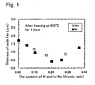
- a coating film was formed by setting a Cr-Al alloy target, a Cr-Al-W alloy target or a Cr-Al-Mo alloy target in a film forming apparatus shown in Fig. 3 .
- a cemented carbide subjected to mirror quality polishing was used as the base material for the measurements of the composition, crystal structure and hardness of the coating film and thickness of oxide film after oxidation treatment (oxidation resistance), and ball end mill made of cemented carbide of 5R was used for the evaluation of cutting performance.
- the coating was formed by heating the base material (workpiece) to a temperatures of about 500°C with a heater installed in the chamber, and carrying out sputter cleaning with Ar ions.
- a target 6 inches in diameter was used and the input power was set to 2 kW.
- a target 100 mm in diameter was used and arc current of 150 A was supplied.
- N 2 atmosphere with total pressure of 2.7 Pa was used.
- composition, crystal structure and hardness of the coating film and thickness of oxide film after oxidation treatment (oxidation resistance) of the coating film that has been formed on the cemented carbide subjected to mirror quality polishing as described above were measured as follows.
- composition of the coating was measured by EPMA.
- Crystal structure was identified by X-ray diffraction analysis.
- C indicates cubic crystal and H indicates hexagonal crystal.
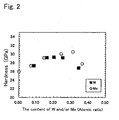
- Hardness was measured with Micro-Vickers hardness meter by applying a load of 0.245 N.
- the thickness of the oxide film formed on the surface was measured at three points, with the measured values averaged to evaluate the oxidation resistance.
- a ball end mill made of cemented carbide coated with a film as described above was used in a cutting test under the following conditions, and wear resistance of the coating film was evaluated by means of the amount of wear of the flank measured on the periphery.
- Table 1 No. Film forming method Composition of film (Atomic ratio) Crystal structure Hardness HV Thickness of oxide film ⁇ m Amount of wear ⁇ m Cr Al W Mo C N 1 AIP 0.5 0.5 0 0 0 1 C 2500 1.70 250.0 2 AIP 0.5 0.48 0.02 0 0 1 C 2397 1.39 226.0 2' AIP 0.48 0.48 0.06 0 0 1 C 2500 0.89 120.0.
- Sample No. 15 that includes low content of Al shows low hardness, poor oxidation resistance and significant amount of wear during cutting test.
- Samples Nos. 19 and 20 that include excessive amount of Al show low hardness and poor wear resistance.
- Sample No. 25 that has high proportion of N atoms shows low hardness, low oxidation resistance and low wear resistance.
- a coating film was formed by setting the target in a film forming apparatus shown in Fig. 3 .
- the target was made of Cr-Al alloy, Cr-Al-W alloy, Cr-Al-W-Si alloy, Cr-Al-W-B alloy or Cr-Al-W-B-Si alloy.
- a cemented carbide subjected to mirror quality polishing was used as the base material for the measurement of composition, crystal structure and hardness of the coating film and thickness of oxide film after oxidation treatment (oxidation resistance), and a ball end mill made of cemented carbide of 5R was used for the evaluation of cutting performance.
- the coating film was formed by heating the base material (workpiece) to a temperature of about 500°C with a heater installed in the chamber, and carrying out sputter cleaning with Ar ions.
- a target 6 inches in diameter was used and the input power was set to 2 kW.
- a target 100 mm in diameter was used and arc current of 150 A was supplied.
- N 2 atmosphere with total pressure of 2.7 Pa was used.
- Film forming method Composition of film (Atomic ratio) Crystal structure Hardness HV Thickness of oxide film ⁇ m Amount of wear ⁇ m Cr Al W Mo B Si C N 1 AIP 0.5 0.5 0 0 0 0 0 1 C 2375 1.7 250 2 AIP 0.31 0.51 0.18 0 0 0 0 1 C 2820 0.44 56.5 3 AIP 0.28 0.51 0.18 0 0 0.03 0 1 C 2867 0.39 50.9 4 AIP 0.24 0.51 0.18 0 0 0.07 0 1 C 2820 0.32 45.2 5 AIP 0.16 0.51 0.18 0 0 0.15 0 1 C+H 2773 0.26 84.8 6 AIP 0.08 0.51 0.18 0 0 0.23 0 1 H 2444 0.22 135.6 7 AIP 0.27 0.51 0.18 0 0.04 0 0 1 C 2820 0.42 54.2 8 AIP 0.22 0.51 0.18 0 0.09 0 0 1 C 2867 0.38 50.9 9 AIP 0.06 0.51 0.18
- Samples Nos. 9 and 19 that have high proportion of (Si+B) atoms show significant amounts of wear during cutting test because hexagonal crystal was generated.
- Sample No. 25 that has high proportion of N atoms shows low hardness, poor wear resistance and low oxidation resistance.
- Predetermined quantities of Al powder, Ti powder, Cr powder, W powder, Mo powder, Si powder and B powder that passed 100 mesh sieve were mixed.
- the mixture was used to make targets of various compositions shown in Table 4 or Table 5 by HIP process at a temperature of 500 °C under pressure of 100 MPa, hot forging at a temperature of 400 °C or hot press process (sintering temperature 550 °C).
- Composition of the target was measured by X-ray fluorescence analysis.
- Target manufacturing method Composition of target (Atomic ratio) Density % Film forming method Surface roughness ⁇ m Hardness HV Cr Al W Mo B si 1 HIP 0.24 0.51 0.18 0 0 0.07 95 AIP 0.1955 2760 2 HIP 0.24 0.51 0.18 0 0 0.07 100 AIP 0.0575 2806 3 Hot forging 0.24 0.51 0.18 0 0 0.07 85 AIP 0.4025 2576 4 Hot forging 0.24 0.51 0.18 0 0 0.07 91 AIP 0.345 2622 5 Hot forging 0.24 0.51 0.18 0 0 0.07 95 AIP 0.1955 2714 6 Hot forging 0.24 0.51 0.18 0 0 0.07 100 AIP 0.0575 2806 7 Hot press 0.24 0.51 0.18 0 0 0.07 87 AIP 0.345 2622 8 Hot press 0.24 0.51 0.18 0 0 0.07 90 AIP 0.115 2576 9 HIP 0.21 0.51 0 0.18 0.1 0 95 Sputter 0.0345 2760 10 HIP 0.
- Target manufacturing method Composition of target (Atomic ratios) Density % Film forming method Surface roughness ⁇ m hardiness HV Ti Al W Mo B Si 21 HIP 0.24 0.51 0.18 0 0 0.07 95 AIP 0.17 3000 22 HIP 0.24 0.51 0.18 0 0 0.07 100 AIP 0.05 3050 23 Hot forging 0.24 0.51 0.18 0 0 0.07 85 AIP 0.35 2800 24 Hot forging 0.24 0.51 0.18 0 0 0.07 91 AIP 0.3 2850 25 Hot forging 0.24 0.51 0.18 0 0 0.07 95 AIP 0.17 2950 26 Hot forging 0.24 0.51 0.18 0 0 0.07 100 AIP 0.05 3050 27 Hot press 0.24 0.51 0.18 0 0 0.07 87 AIP 0.3 2850 28 Hot press 0.24 0.51 0.18 0 0 0.07 90 AIP 0.1 2800 29 HIP 0.21 0.51 0 0.18 0.1 0 95 Sputter 0.03 3000 30 HIP 0.21 0.51 0 0.18
- a coating film having the composition shown in Table 6 was formed by setting a target that contained Ti, Cr, Al, W and Mo in a film forming apparatus having an UBMS and an AIP evaporation source shown in Fig. 4 , and using the UBMS or the AIP evaporation source.
- a cemented carbide base material was used in the measurements of structure and composition of the coating, and friction coefficient at high temperature, and a square end mill made of cemented carbide (six-blade) was used in the cutting test.
- the base material was placed in the chamber that was evacuated to create vacuum.
- the coating was formed by heating the base material (workpiece) to a temperature of about 500°C while carrying out sputter cleaning with Ar ions with Ar pressure of 0.6 Pa and bias voltage of -500 V applied to the base material for three minutes.
- a bias voltage of 70 V was applied to the base material in an atmosphere of Ar-nitrogen gas mixture or Ar-nitrogen-methane gas mixture (total pressure 0.6 Pa).
- a bias voltage of 70 V was applied to the base material in an atmosphere of nitrogen gas or nitrogen-methane gas mixture (total pressure 4 Pa), while supplying arc current of 150 A.
- the coating was formed to thickness of about 3 ⁇ m in either case.
- composition, crystal structure and hardness of the coating film and friction coefficient at high temperature (high-temperature anti-friction property) of the coating film that has been formed as described above were measured as follows.
- composition of the coating was measured by EPMA.
- Crystal structure was identified by X-ray diffraction analysis.
- B1 indicates cubic crystal and B4 indicates hexagonal crystal.
- Hardness was measured with Micro-Vickers hardness meter by applying a load of 0.245 N for 15 seconds.
- Friction coefficient of the coating film with an alloy tool steel for hot dies (SKD61, HRC50) at a high temperature was measured after both members had made relative movement of sliding over a distance of 1000 m at a speed of 0.3 m/s under a vertical load of 2 N at 800 °C in air atmosphere.
- the coating film of Sample No. 10 that satisfies the requirements of the present invention shows excellent high-temperature anti-friction performance and high hardness while keeping the amount of wear during cutting test at a low level.
- the coating film that does not satisfy the requirements of the present invention shows poor high-temperature anti-friction performance, low hardness or significant amount of wear during cutting test.
- samples Nos. 1 through:4 that do not include element M or include less than the specified amount of element M show poor high-temperature anti-friction performance and significant amount of wear during cutting test.
- Sample No. 8 that includes excessive amount of element M shows a significant amount of wear during cutting test.
- Sample No. 9 that includes a very low content of Al shows low hardness and a significant amount of wear during cutting test.
- Sample No. 12 that includes an excessive amount of Al shows significant softening of the coating and a large amount of wear during cutting test.
- Sample No. 15 that includes an excessive amount of C shows lower hardness.
- Sample No. 16 that includes an excessive amount of Ti and accordingly a relatively low content of Al shows lower hardness and a large amount of wear during cutting test.
- a coating film that further included Si and/or B was formed and characteristics thereof were studied.
- a target including Ti, Cr, Al, element M, Si and/or B was set in the film forming apparatus shown in Fig. 4 to form the coating film having the composition shown in Table 7, similarly to Example 4. Characteristics of the coating thus obtained were evaluated similarly to Example 4. The results are shown in Table 7. Table 7 No.
- the coating film of samples N° 30 and 31 that satisfies the requirements of the present invention shows excellent high-temperature anti-friction performance, high Vickers hardness and an amount of wear during cutting test kept at a low level.
- the hard coating that includes Si and/or B tends to have higher high-temperature anti-friction performance.
- the coating film that does not satisfy the requirements of the present invention shows poor high-temperature anti-friction performance, low hardness or a significant amount of wear during cutting test.
- sample No. 21 that includes an excessive content of Ti shows a large amount of wear during cutting test.
- Sample No. 23 that does not include element M shows poor high-temperature anti-friction performance and a significant amount of wear during cutting test.
Claims (3)
- Revêtement dur ayant une excellente performance antifriction à haute température et une excellente résistance à l'usure, qui comprend une composition représentée par la formule :
(Tia, Crb, Ale, Sid, Be, M1-a-b-e-d-e) (C1-fNf)
dans laquelle M représente Mo, et également dans laquelle a, b, c, d, e et f qui représentent les rapports atomiques de Ti, Cr, Al, Si, B et N, respectivement, satisfont les relations suivantes :


- Revêtement dur ayant une excellente performance antifriction à haute température et une excellente résistance à l'usure selon la revendication 1, qui comprend une composition représentée par la formule :
(Tia, Crb, Ale, Sid, Be, M1-a-b-e-d-e) (C1-fNf)
dans laquelle M représente Mo, et également dans laquelle a, b, c, d, e et f qui représentent les rapports atomiques de Ti, Cr, Al, Si, B et N, respectivement, satisfont les relations suivantes :


- Revêtement dur ayant une excellente performance antifriction à haute température et une excellente résistance à l'usure selon la revendication 2, qui comprend une composition représentée par la formule :
(Tia, Crb, Alc, Sid, Be, M1-a-b-c-d-e) (C1-fNf)
dans laquelle M représente Mo ; et également dans laquelle a, b, c, d, e et f qui représentent les rapports atomiques de Ti, Cr, Al, Si, B et N, respectivement, satisfont les relations suivantes :


Applications Claiming Priority (3)
| Application Number | Priority Date | Filing Date | Title |
|---|---|---|---|
| JP2004288042 | 2004-09-30 | ||
| JP2005246660A JP5060714B2 (ja) | 2004-09-30 | 2005-08-26 | 耐摩耗性および耐酸化性に優れた硬質皮膜、並びに該硬質皮膜形成用ターゲット |
| EP05021350.3A EP1642996B1 (fr) | 2004-09-30 | 2005-09-29 | Revêtement dur excellent en resistance à l'abrasion et à l'oxidation et target pour son manufacture |
Related Parent Applications (3)
| Application Number | Title | Priority Date | Filing Date |
|---|---|---|---|
| EP05021350.3 Division | 2005-09-29 | ||
| EP05021350.3A Division-Into EP1642996B1 (fr) | 2004-09-30 | 2005-09-29 | Revêtement dur excellent en resistance à l'abrasion et à l'oxidation et target pour son manufacture |
| EP05021350.3A Division EP1642996B1 (fr) | 2004-09-30 | 2005-09-29 | Revêtement dur excellent en resistance à l'abrasion et à l'oxidation et target pour son manufacture |
Publications (3)
| Publication Number | Publication Date |
|---|---|
| EP1992713A2 EP1992713A2 (fr) | 2008-11-19 |
| EP1992713A3 EP1992713A3 (fr) | 2009-10-21 |
| EP1992713B1 true EP1992713B1 (fr) | 2012-03-21 |
Family
ID=35453518
Family Applications (3)
| Application Number | Title | Priority Date | Filing Date |
|---|---|---|---|
| EP05021350.3A Not-in-force EP1642996B1 (fr) | 2004-09-30 | 2005-09-29 | Revêtement dur excellent en resistance à l'abrasion et à l'oxidation et target pour son manufacture |
| EP20080013690 Not-in-force EP1992713B1 (fr) | 2004-09-30 | 2005-09-29 | Revêtement dur ayant une excellente résistance à l'usure et à l'oxydation et cible de formation correspondante |
| EP20070010972 Not-in-force EP1849883B1 (fr) | 2004-09-30 | 2005-09-29 | Revêtement dur ayant une excellente résistance à l'usure et à l'oxydation. |
Family Applications Before (1)
| Application Number | Title | Priority Date | Filing Date |
|---|---|---|---|
| EP05021350.3A Not-in-force EP1642996B1 (fr) | 2004-09-30 | 2005-09-29 | Revêtement dur excellent en resistance à l'abrasion et à l'oxidation et target pour son manufacture |
Family Applications After (1)
| Application Number | Title | Priority Date | Filing Date |
|---|---|---|---|
| EP20070010972 Not-in-force EP1849883B1 (fr) | 2004-09-30 | 2005-09-29 | Revêtement dur ayant une excellente résistance à l'usure et à l'oxydation. |
Country Status (5)
| Country | Link |
|---|---|
| US (2) | US7521131B2 (fr) |
| EP (3) | EP1642996B1 (fr) |
| JP (1) | JP5060714B2 (fr) |
| KR (2) | KR100937072B1 (fr) |
| TW (1) | TWI356767B (fr) |
Cited By (1)
| Publication number | Priority date | Publication date | Assignee | Title |
|---|---|---|---|---|
| CN111809075A (zh) * | 2020-07-03 | 2020-10-23 | 西安石油大学 | 一种Ti镀层Ti3AlC2颗粒增强Al基内燃机活塞连杆及其制造方法 |
Families Citing this family (48)
| Publication number | Priority date | Publication date | Assignee | Title |
|---|---|---|---|---|
| JP4713413B2 (ja) | 2006-06-30 | 2011-06-29 | 株式会社神戸製鋼所 | 硬質皮膜およびその製造方法 |
| AU2007302162B2 (en) * | 2006-09-26 | 2012-06-28 | Oerlikon Trading Ag, Truebbach | Workpiece with hard coating |
| JP5188133B2 (ja) * | 2006-09-27 | 2013-04-24 | 京セラ株式会社 | 切削工具 |
| JP5037931B2 (ja) * | 2006-12-25 | 2012-10-03 | 京セラ株式会社 | 表面被覆工具 |
| JP5038303B2 (ja) * | 2006-12-25 | 2012-10-03 | 京セラ株式会社 | 表面被覆工具および被切削物の加工方法 |
| CN101617061B (zh) | 2007-02-26 | 2012-04-25 | 京瓷株式会社 | Ti基金属陶瓷 |
| CN101368260A (zh) * | 2007-09-14 | 2009-02-18 | 山特维克知识产权股份有限公司 | 用于在基底上沉积涂层的方法和设备 |
| US8080324B2 (en) * | 2007-12-03 | 2011-12-20 | Kobe Steel, Ltd. | Hard coating excellent in sliding property and method for forming same |
| JP5094368B2 (ja) * | 2007-12-25 | 2012-12-12 | 京セラ株式会社 | 切削工具 |
| JP5121486B2 (ja) * | 2008-02-12 | 2013-01-16 | 京セラ株式会社 | 切削工具 |
| JP4987081B2 (ja) * | 2008-03-26 | 2012-07-25 | 京セラ株式会社 | 切削工具 |
| GB0808366D0 (en) * | 2008-05-09 | 2008-06-18 | Element Six Ltd | Attachable wear resistant percussive drilling head |
| JP5111259B2 (ja) * | 2008-06-26 | 2013-01-09 | 京セラ株式会社 | 表面被覆部材 |
| PL2310549T3 (pl) * | 2008-07-09 | 2018-06-29 | Oerlikon Surface Solutions Ltd., Pfäffikon | System powłokowy, powlekany przedmiot obrabiany oraz sposób wytwarzania powlekanego przedmiotu obrabianego |
| JP5267985B2 (ja) * | 2008-12-09 | 2013-08-21 | 住友電工ハードメタル株式会社 | 表面被覆切削工具 |
| JP5193153B2 (ja) | 2009-10-02 | 2013-05-08 | 株式会社神戸製鋼所 | 硬質皮膜、塑性加工用金型、塑性加工方法、及び硬質皮膜用ターゲット |
| KR101616600B1 (ko) * | 2009-11-12 | 2016-04-28 | 오에스지 가부시키가이샤 | 경질 피막 피복 공구 |
| KR101635486B1 (ko) * | 2010-03-25 | 2016-07-01 | 쿄세라 코포레이션 | 절삭 공구 |
| WO2011122553A1 (fr) * | 2010-03-29 | 2011-10-06 | 京セラ株式会社 | Outil de coupe |
| WO2011122554A1 (fr) * | 2010-03-29 | 2011-10-06 | 京セラ株式会社 | Outil de coupe |
| JP5582565B2 (ja) * | 2010-07-01 | 2014-09-03 | 岡山県 | 硬質皮膜及びその製造方法 |
| KR101685450B1 (ko) * | 2010-09-29 | 2016-12-12 | 쿄세라 코포레이션 | 절삭 공구 |
| JP5610218B2 (ja) * | 2010-11-30 | 2014-10-22 | オーエスジー株式会社 | 切削工具用硬質被膜及び硬質被膜被覆切削工具 |
| JP5610219B2 (ja) * | 2010-11-30 | 2014-10-22 | オーエスジー株式会社 | 切削工具用硬質被膜及び硬質被膜被覆切削工具 |
| RU2454474C1 (ru) * | 2011-02-25 | 2012-06-27 | Федеральное государственное бюджетное учреждение науки Институт физики прочности и материаловедения Сибирского отделения Российской академии наук (ИФПМ СО РАН) | Шихта для композиционного катода и способ его изготовления |
| JP5669016B2 (ja) * | 2011-04-18 | 2015-02-12 | 三菱マテリアル株式会社 | スパッタリングターゲットおよびその製造方法 |
| EP2761050B1 (fr) * | 2011-09-30 | 2021-08-25 | CemeCon AG | Revêtement de substrats par pulvérisation magnétron pulsé de grande puissance |
| JP5559131B2 (ja) * | 2011-11-22 | 2014-07-23 | 株式会社神戸製鋼所 | 硬質皮膜および硬質皮膜被覆工具 |
| TW201321542A (zh) * | 2011-11-29 | 2013-06-01 | Chenming Mold Ind Corp | 製造ic屏蔽鍍膜之設備及ic之金屬屏蔽膜層 |
| EP2628817B1 (fr) * | 2012-02-15 | 2016-11-02 | IHI Hauzer Techno Coating B.V. | Article revêtu d'acier martensitique et procédé de formation d'un article revêtu d'acier |
| JP5991529B2 (ja) * | 2012-10-29 | 2016-09-14 | 三菱マテリアル株式会社 | 耐欠損性と耐摩耗性にすぐれた表面被覆切削工具 |
| JP6064549B2 (ja) * | 2012-11-28 | 2017-01-25 | 住友電気工業株式会社 | 焼結体および焼結体の製造方法 |
| JP2014122400A (ja) | 2012-12-21 | 2014-07-03 | Kobe Steel Ltd | 軟質金属に対する耐凝着性に優れた硬質皮膜 |
| JP6055324B2 (ja) * | 2013-01-29 | 2016-12-27 | 株式会社神戸製鋼所 | 軟質金属に対する耐凝着性に優れた硬質皮膜 |
| CN103273696B (zh) * | 2013-05-22 | 2015-10-21 | 安徽工程大学 | 一种减摩耐磨涂层及其制备工艺 |
| WO2015146617A1 (fr) * | 2014-03-26 | 2015-10-01 | Jx日鉱日石金属株式会社 | Cible de pulvérisation comprenant du carbure de tungstène ou du carbure de titane |
| CN105331939B (zh) * | 2014-08-15 | 2018-05-11 | 安泰科技股份有限公司 | 一种含硅合金靶材及其制备方法 |
| CN105483432B (zh) * | 2015-12-03 | 2017-08-25 | 上海理工大学 | 一种钛合金耐磨层及其制备方法 |
| JP2017110248A (ja) * | 2015-12-15 | 2017-06-22 | 株式会社神戸製鋼所 | 硬質皮膜及び金型 |
| CN106244876A (zh) * | 2016-08-17 | 2016-12-21 | 任静儿 | 一种铝合金导线制备方法 |
| JP7025693B2 (ja) * | 2018-01-04 | 2022-02-25 | 三菱マテリアル株式会社 | 表面被覆切削工具 |
| JP7110352B2 (ja) * | 2018-08-01 | 2022-08-01 | オーエスジー株式会社 | 硬質被膜および硬質被膜被覆部材 |
| KR102520304B1 (ko) | 2018-08-01 | 2023-04-10 | 오에스지 가부시키가이샤 | 경질 피막 및 경질 피막 피복 부재 |
| CN109735806B (zh) * | 2019-01-21 | 2021-08-03 | 超微中程纳米科技(苏州)有限公司 | 一种铣刀纳米涂层及其制备方法 |
| CN110144477B (zh) * | 2019-05-23 | 2020-12-01 | 西安建筑科技大学 | 一种Ag/Ti2AlNb自润滑梯度复合材料的制备方法 |
| WO2022244190A1 (fr) * | 2021-05-20 | 2022-11-24 | 住友電工ハードメタル株式会社 | Outil de coupe |
| CN113817983B (zh) * | 2021-11-24 | 2022-03-18 | 武汉中维创发工业研究院有限公司 | 黑色纳米复合材料及其制备方法和应用 |
| CN115181951B (zh) * | 2022-07-13 | 2023-04-28 | 南昌航空大学 | 一种高速钢搅拌摩擦焊搅拌头用多层涂层及其制备方法 |
Family Cites Families (25)
| Publication number | Priority date | Publication date | Assignee | Title |
|---|---|---|---|---|
| US4714660A (en) * | 1985-12-23 | 1987-12-22 | Fansteel Inc. | Hard coatings with multiphase microstructures |
| JP2917312B2 (ja) | 1989-09-29 | 1999-07-12 | 住友電気工業株式会社 | 切削・耐摩工具用表面被覆超硬部材 |
| CH688863A5 (de) * | 1994-06-24 | 1998-04-30 | Balzers Hochvakuum | Verfahren zum Beschichten mindestens eines Werkstueckes und Anlage hierfuer. |
| JP2860064B2 (ja) * | 1994-10-17 | 1999-02-24 | 株式会社神戸製鋼所 | Ti−Al合金ターゲット材の製造方法 |
| JP3418850B2 (ja) | 1995-06-20 | 2003-06-23 | 株式会社アライドマテリアル | スパッターターゲット材及びその製造方法 |
| EP0855451A4 (fr) * | 1995-10-12 | 1999-10-06 | Toshiba Kk | Film de cablage, cible de pulverisation par bombardement ionique destinee a la formation de ce film et composant electronique comportant ce film |
| JP3452726B2 (ja) * | 1996-06-05 | 2003-09-29 | 日立ツール株式会社 | 多層被覆硬質工具 |
| JPH1018024A (ja) | 1996-07-05 | 1998-01-20 | Hitachi Metals Ltd | 被覆硬質部材 |
| JP4528373B2 (ja) | 1997-02-20 | 2010-08-18 | 住友電工ハードメタル株式会社 | 被覆工具およびその製造方法 |
| US5981049A (en) * | 1996-12-04 | 1999-11-09 | Sumitomo Electric Industries, Ltd. | Coated tool and method of manufacturing the same |
| JP2000325108A (ja) | 1999-05-17 | 2000-11-28 | Hidekazu Sato | 工事用足先保護具 |
| JP3347687B2 (ja) | 1999-05-19 | 2002-11-20 | 日立ツール株式会社 | 硬質皮膜被覆工具 |
| ATE343659T1 (de) * | 2000-12-28 | 2006-11-15 | Kobe Steel Ltd | Hartstoffschicht für schneidwerkzeuge |
| JP2002254208A (ja) | 2001-02-23 | 2002-09-10 | Hitachi Metals Ltd | 耐酸化性および耐摩耗性に優れた工具 |
| JP3912494B2 (ja) | 2002-01-21 | 2007-05-09 | 三菱マテリアル株式会社 | 硬質被覆層がすぐれた耐熱塑性変形性を発揮する表面被覆超硬合金製スローアウエイチップ |
| JP4216518B2 (ja) * | 2002-03-29 | 2009-01-28 | 株式会社神戸製鋼所 | カソード放電型アークイオンプレーティング用ターゲットおよびその製造方法 |
| JP2004066402A (ja) * | 2002-08-07 | 2004-03-04 | Mitsubishi Heavy Ind Ltd | 切削工具及びこれを備えた切削装置 |
| SE526339C2 (sv) | 2002-09-04 | 2005-08-23 | Seco Tools Ab | Skär med slitstark refraktär beläggning med kompositstruktur |
| JP4330859B2 (ja) | 2002-09-11 | 2009-09-16 | 株式会社タンガロイ | 被覆超硬合金およびその製造方法 |
| PT1422311E (pt) * | 2002-11-19 | 2007-03-30 | Hitachi Tool Eng | Película dura e ferramenta revestida por película dura |
| EP2275585A1 (fr) * | 2003-04-28 | 2011-01-19 | Oerlikon Trading AG, Trübbach | Pièce à usiner comportant une couche de matière dure contenant alcr et procédé de fabrication associé |
| JP3781374B2 (ja) * | 2003-12-09 | 2006-05-31 | 日立ツール株式会社 | 硬質皮膜被覆工具及びその製造方法 |
| JP2004130514A (ja) | 2004-01-23 | 2004-04-30 | Hitachi Tool Engineering Ltd | 硬質皮膜被覆工具及びその製造方法 |
| MX2007000405A (es) * | 2004-07-15 | 2007-06-25 | Oc Oerlikon Balzers Ag | Recubrimiento duro altamente resistente a la oxidacion para herramientas de corte. |
| JP5443403B2 (ja) * | 2004-09-30 | 2014-03-19 | 株式会社神戸製鋼所 | 高温潤滑性と耐摩耗性に優れた硬質皮膜および該硬質皮膜形成用ターゲット |
-
2005
- 2005-08-26 JP JP2005246660A patent/JP5060714B2/ja not_active Expired - Fee Related
- 2005-09-28 TW TW94133818A patent/TWI356767B/zh not_active IP Right Cessation
- 2005-09-29 EP EP05021350.3A patent/EP1642996B1/fr not_active Not-in-force
- 2005-09-29 EP EP20080013690 patent/EP1992713B1/fr not_active Not-in-force
- 2005-09-29 US US11/237,798 patent/US7521131B2/en not_active Expired - Fee Related
- 2005-09-29 EP EP20070010972 patent/EP1849883B1/fr not_active Not-in-force
- 2005-09-30 KR KR1020050092070A patent/KR100937072B1/ko active IP Right Grant
-
2009
- 2009-01-29 US US12/362,016 patent/US7601440B2/en not_active Expired - Fee Related
- 2009-08-14 KR KR1020090075109A patent/KR101011549B1/ko active IP Right Grant
Cited By (1)
| Publication number | Priority date | Publication date | Assignee | Title |
|---|---|---|---|---|
| CN111809075A (zh) * | 2020-07-03 | 2020-10-23 | 西安石油大学 | 一种Ti镀层Ti3AlC2颗粒增强Al基内燃机活塞连杆及其制造方法 |
Also Published As
| Publication number | Publication date |
|---|---|
| EP1849883A8 (fr) | 2008-02-27 |
| EP1642996A2 (fr) | 2006-04-05 |
| EP1642996B1 (fr) | 2017-07-19 |
| KR20060051931A (ko) | 2006-05-19 |
| EP1642996A3 (fr) | 2006-12-06 |
| US20090136727A1 (en) | 2009-05-28 |
| EP1992713A2 (fr) | 2008-11-19 |
| KR101011549B1 (ko) | 2011-01-27 |
| EP1849883A2 (fr) | 2007-10-31 |
| KR100937072B1 (ko) | 2010-01-15 |
| JP5060714B2 (ja) | 2012-10-31 |
| EP1992713A3 (fr) | 2009-10-21 |
| TW200624250A (en) | 2006-07-16 |
| TWI356767B (en) | 2012-01-21 |
| EP1849883A3 (fr) | 2008-08-27 |
| US7601440B2 (en) | 2009-10-13 |
| KR20090094062A (ko) | 2009-09-03 |
| US7521131B2 (en) | 2009-04-21 |
| JP2006123159A (ja) | 2006-05-18 |
| US20060068225A1 (en) | 2006-03-30 |
| EP1849883B1 (fr) | 2015-03-18 |
Similar Documents
| Publication | Publication Date | Title |
|---|---|---|
| EP1992713B1 (fr) | Revêtement dur ayant une excellente résistance à l'usure et à l'oxydation et cible de formation correspondante | |
| EP1726686B1 (fr) | Piéce ayant un revêtement dur | |
| EP1688513B1 (fr) | Revêtement dur, cible pour former un revêtement dur, et procédé de fabrication d'un revêtement dur | |
| EP1347076B1 (fr) | Plaquette de coupe revêtue par PVD pour outil de coupe | |
| EP1842610B1 (fr) | Outil de coupe a revetement de surface et son procede de fabrication | |
| US7901796B2 (en) | Coated cutting tool and manufacturing method thereof | |
| EP2116628B1 (fr) | Film de revêtement dur et cible de formation associé | |
| JP5695720B2 (ja) | 耐摩耗性と耐酸化性に優れた硬質皮膜 | |
| EP1710032B1 (fr) | Outil de coupe en alliage grande duret surface revetue, et methode pour sa fabrication sb /sb | |
| US20080299366A1 (en) | Cemented carbide insert | |
| EP2295616A1 (fr) | Couche de revêtement dure et procédé pour former celle-ci | |
| EP3109341A1 (fr) | Film de revêtement dur et procédé de formation de ce dernier | |
| CN113453828A (zh) | 硬质皮膜切削工具 | |
| JP4535250B2 (ja) | 高硬度鋼の高速切削加工で硬質被覆層がすぐれた耐摩耗性を発揮する表面被覆超硬合金製切削工具の製造方法 |
Legal Events
| Date | Code | Title | Description |
|---|---|---|---|
| PUAI | Public reference made under article 153(3) epc to a published international application that has entered the european phase |
Free format text: ORIGINAL CODE: 0009012 |
|
| 17P | Request for examination filed |
Effective date: 20080807 |
|
| AC | Divisional application: reference to earlier application |
Ref document number: 1642996 Country of ref document: EP Kind code of ref document: P |
|
| AK | Designated contracting states |
Kind code of ref document: A2 Designated state(s): CH CZ DE ES FR LI SE |
|
| PUAL | Search report despatched |
Free format text: ORIGINAL CODE: 0009013 |
|
| AK | Designated contracting states |
Kind code of ref document: A3 Designated state(s): CH CZ DE ES FR LI SE |
|
| AKX | Designation fees paid |
Designated state(s): CH CZ DE ES FR LI SE |
|
| GRAP | Despatch of communication of intention to grant a patent |
Free format text: ORIGINAL CODE: EPIDOSNIGR1 |
|
| GRAS | Grant fee paid |
Free format text: ORIGINAL CODE: EPIDOSNIGR3 |
|
| GRAA | (expected) grant |
Free format text: ORIGINAL CODE: 0009210 |
|
| AC | Divisional application: reference to earlier application |
Ref document number: 1642996 Country of ref document: EP Kind code of ref document: P |
|
| AK | Designated contracting states |
Kind code of ref document: B1 Designated state(s): CH CZ DE ES FR LI SE |
|
| REG | Reference to a national code |
Ref country code: CH Ref legal event code: NV Representative=s name: E. BLUM & CO. AG PATENT- UND MARKENANWAELTE VSP Ref country code: CH Ref legal event code: EP |
|
| REG | Reference to a national code |
Ref country code: DE Ref legal event code: R096 Ref document number: 602005033321 Country of ref document: DE Effective date: 20120516 |
|
| REG | Reference to a national code |
Ref country code: SE Ref legal event code: TRGR |
|
| PG25 | Lapsed in a contracting state [announced via postgrant information from national office to epo] |
Ref country code: CZ Free format text: LAPSE BECAUSE OF FAILURE TO SUBMIT A TRANSLATION OF THE DESCRIPTION OR TO PAY THE FEE WITHIN THE PRESCRIBED TIME-LIMIT Effective date: 20120321 |
|
| PLBE | No opposition filed within time limit |
Free format text: ORIGINAL CODE: 0009261 |
|
| STAA | Information on the status of an ep patent application or granted ep patent |
Free format text: STATUS: NO OPPOSITION FILED WITHIN TIME LIMIT |
|
| 26N | No opposition filed |
Effective date: 20130102 |
|
| REG | Reference to a national code |
Ref country code: DE Ref legal event code: R097 Ref document number: 602005033321 Country of ref document: DE Effective date: 20130102 |
|
| PG25 | Lapsed in a contracting state [announced via postgrant information from national office to epo] |
Ref country code: ES Free format text: LAPSE BECAUSE OF FAILURE TO SUBMIT A TRANSLATION OF THE DESCRIPTION OR TO PAY THE FEE WITHIN THE PRESCRIBED TIME-LIMIT Effective date: 20120702 |
|
| REG | Reference to a national code |
Ref country code: FR Ref legal event code: ST Effective date: 20130531 |
|
| PG25 | Lapsed in a contracting state [announced via postgrant information from national office to epo] |
Ref country code: FR Free format text: LAPSE BECAUSE OF NON-PAYMENT OF DUE FEES Effective date: 20121001 |
|
| PGFP | Annual fee paid to national office [announced via postgrant information from national office to epo] |
Ref country code: DE Payment date: 20190917 Year of fee payment: 15 Ref country code: SE Payment date: 20190910 Year of fee payment: 15 |
|
| PGFP | Annual fee paid to national office [announced via postgrant information from national office to epo] |
Ref country code: CH Payment date: 20190913 Year of fee payment: 15 |
|
| REG | Reference to a national code |
Ref country code: DE Ref legal event code: R119 Ref document number: 602005033321 Country of ref document: DE |
|
| REG | Reference to a national code |
Ref country code: CH Ref legal event code: PL |
|
| PG25 | Lapsed in a contracting state [announced via postgrant information from national office to epo] |
Ref country code: DE Free format text: LAPSE BECAUSE OF NON-PAYMENT OF DUE FEES Effective date: 20210401 |
|
| PG25 | Lapsed in a contracting state [announced via postgrant information from national office to epo] |
Ref country code: SE Free format text: LAPSE BECAUSE OF NON-PAYMENT OF DUE FEES Effective date: 20200930 Ref country code: LI Free format text: LAPSE BECAUSE OF NON-PAYMENT OF DUE FEES Effective date: 20200930 Ref country code: CH Free format text: LAPSE BECAUSE OF NON-PAYMENT OF DUE FEES Effective date: 20200930 |
|
| REG | Reference to a national code |
Ref country code: SE Ref legal event code: EUG |