EP1985884A1 - Elektrische bremse - Google Patents
Elektrische bremse Download PDFInfo
- Publication number
- EP1985884A1 EP1985884A1 EP06713720A EP06713720A EP1985884A1 EP 1985884 A1 EP1985884 A1 EP 1985884A1 EP 06713720 A EP06713720 A EP 06713720A EP 06713720 A EP06713720 A EP 06713720A EP 1985884 A1 EP1985884 A1 EP 1985884A1
- Authority
- EP
- European Patent Office
- Prior art keywords
- start position
- braking start
- piston
- brake
- braking
- Prior art date
- Legal status (The legal status is an assumption and is not a legal conclusion. Google has not performed a legal analysis and makes no representation as to the accuracy of the status listed.)
- Granted
Links
Images


Classifications
-
- B—PERFORMING OPERATIONS; TRANSPORTING
- B60—VEHICLES IN GENERAL
- B60T—VEHICLE BRAKE CONTROL SYSTEMS OR PARTS THEREOF; BRAKE CONTROL SYSTEMS OR PARTS THEREOF, IN GENERAL; ARRANGEMENT OF BRAKING ELEMENTS ON VEHICLES IN GENERAL; PORTABLE DEVICES FOR PREVENTING UNWANTED MOVEMENT OF VEHICLES; VEHICLE MODIFICATIONS TO FACILITATE COOLING OF BRAKES
- B60T13/00—Transmitting braking action from initiating means to ultimate brake actuator with power assistance or drive; Brake systems incorporating such transmitting means, e.g. air-pressure brake systems
- B60T13/74—Transmitting braking action from initiating means to ultimate brake actuator with power assistance or drive; Brake systems incorporating such transmitting means, e.g. air-pressure brake systems with electrical assistance or drive
- B60T13/741—Transmitting braking action from initiating means to ultimate brake actuator with power assistance or drive; Brake systems incorporating such transmitting means, e.g. air-pressure brake systems with electrical assistance or drive acting on an ultimate actuator
-
- F—MECHANICAL ENGINEERING; LIGHTING; HEATING; WEAPONS; BLASTING
- F16—ENGINEERING ELEMENTS AND UNITS; GENERAL MEASURES FOR PRODUCING AND MAINTAINING EFFECTIVE FUNCTIONING OF MACHINES OR INSTALLATIONS; THERMAL INSULATION IN GENERAL
- F16D—COUPLINGS FOR TRANSMITTING ROTATION; CLUTCHES; BRAKES
- F16D65/00—Parts or details
- F16D65/14—Actuating mechanisms for brakes; Means for initiating operation at a predetermined position
- F16D65/16—Actuating mechanisms for brakes; Means for initiating operation at a predetermined position arranged in or on the brake
- F16D65/18—Actuating mechanisms for brakes; Means for initiating operation at a predetermined position arranged in or on the brake adapted for drawing members together, e.g. for disc brakes
-
- F—MECHANICAL ENGINEERING; LIGHTING; HEATING; WEAPONS; BLASTING
- F16—ENGINEERING ELEMENTS AND UNITS; GENERAL MEASURES FOR PRODUCING AND MAINTAINING EFFECTIVE FUNCTIONING OF MACHINES OR INSTALLATIONS; THERMAL INSULATION IN GENERAL
- F16D—COUPLINGS FOR TRANSMITTING ROTATION; CLUTCHES; BRAKES
- F16D66/00—Arrangements for monitoring working conditions, e.g. wear, temperature
- F16D2066/003—Position, angle or speed
-
- F—MECHANICAL ENGINEERING; LIGHTING; HEATING; WEAPONS; BLASTING
- F16—ENGINEERING ELEMENTS AND UNITS; GENERAL MEASURES FOR PRODUCING AND MAINTAINING EFFECTIVE FUNCTIONING OF MACHINES OR INSTALLATIONS; THERMAL INSULATION IN GENERAL
- F16D—COUPLINGS FOR TRANSMITTING ROTATION; CLUTCHES; BRAKES
- F16D66/00—Arrangements for monitoring working conditions, e.g. wear, temperature
- F16D2066/005—Force, torque, stress or strain
-
- F—MECHANICAL ENGINEERING; LIGHTING; HEATING; WEAPONS; BLASTING
- F16—ENGINEERING ELEMENTS AND UNITS; GENERAL MEASURES FOR PRODUCING AND MAINTAINING EFFECTIVE FUNCTIONING OF MACHINES OR INSTALLATIONS; THERMAL INSULATION IN GENERAL
- F16D—COUPLINGS FOR TRANSMITTING ROTATION; CLUTCHES; BRAKES
- F16D2121/00—Type of actuator operation force
- F16D2121/18—Electric or magnetic
- F16D2121/24—Electric or magnetic using motors
-
- F—MECHANICAL ENGINEERING; LIGHTING; HEATING; WEAPONS; BLASTING
- F16—ENGINEERING ELEMENTS AND UNITS; GENERAL MEASURES FOR PRODUCING AND MAINTAINING EFFECTIVE FUNCTIONING OF MACHINES OR INSTALLATIONS; THERMAL INSULATION IN GENERAL
- F16D—COUPLINGS FOR TRANSMITTING ROTATION; CLUTCHES; BRAKES
- F16D2125/00—Components of actuators
- F16D2125/18—Mechanical mechanisms
- F16D2125/20—Mechanical mechanisms converting rotation to linear movement or vice versa
- F16D2125/34—Mechanical mechanisms converting rotation to linear movement or vice versa acting in the direction of the axis of rotation
- F16D2125/40—Screw-and-nut
Definitions
- the present invention relates to a brake apparatus for an automobile, and particularly to an electric brake apparatus which generates braking force using an electric motor.
- the electric brake apparatus proposed in JP-A-2001-32868 comprises an actuator having an electric motor, and is adapted to apply braking force to a wheel by pressing a brake pad against a disc rotor depending on the amount of stepping of a brake pedal.
- the electric brake apparatus in the above conventional example uses the position of the brake pad at the time of releasing thrust detected by a thrust sensor when braking is finished as a braking start position; controls a gap between the brake rotor and the brake pad (hereinafter referred to as a pad gap) so that the brake pad is spaced from the braking start position by a predetermined amount when the brake is released; and controls the thrust of a piston depending on the thrust detected by the thrust sensor when generating the braking force.
- the temperature of the disc rotor or the temperature of the brake pad (hereinafter referred to as pad temperature) is detected by a temperature sensor, or the temperature of the disc rotor is estimated based on the cumulative value of heat energy of the disc rotor calculated based on the vehicle speed, the outside air temperature and a braking state, so that the brake pad is spaced from the disc rotor depending on the amount of thermal deformation of the disc rotor.
- the pad gap and the thrust change in accordance with change in temperature of the brake disc and the brake pad. If the braking is released, the pad gap is increased due to thermal contraction of the brake pad in connection with cooling thereof, and wasteful time until starting the braking will be increased. In addition, if the temperature of the brake pad rises to reduce the hardness (rigidity) of the brake pad during braking, the amount of rotation of the motor for generating predetermined braking force increases and therefore responsiveness of generating the braking force is degraded.
- the temperature of the brake pad changes, the coefficient of friction between the brake pad and the disc rotor changes, and therefore the degree of deceleration of the vehicle may vary even when the brake pad is pressed with the same thrust. Furthermore, if the temperature of the brake pad is lowered during parking braking and the thermal contraction is caused thereby, the thrust decreases, and therefore, the parking brake needs to be set with great braking force in advance in order to compensate the decrease of the thrust, which promotes increase of the electric power consumption and wear of mechanical components. For securing sufficient braking force and responsiveness against these changes of the pad gap and the thrust resulting from change in temperature of the brake pad, it is necessary to grasp the temperature of the brake pad accurately and adjust the control of braking force depending on the temperature change and the thermal expansion.
- the present invention has been made in view of the above problem, and its object is to provide an electric brake apparatus which can estimate the temperature of the brake pad with good accuracy without using a temperature sensor and can secure sufficient braking force and responsiveness even in a situation where the temperature of the brake pad varies.
- a drive controller storing a braking start position detected by a braking start position detecting means as a maximum braking start position, and updating the value of the maximum braking start position when the braking start position shifts in a pressing force increasing direction or when replacement of the brake pad is detected by a pad replacement detecting means.
- the amount of thermal expansion and the amount of wear of the brake pad can be estimated by comparing the maximum braking start position with the braking start position at a high temperature and the braking start position after replacement of the pad, and it becomes possible to provide an electric brake apparatus which can secure sufficient braking force and responsiveness even in a situation where the temperature of the brake pad varies.
- the drive controller utilizes the braking start position detected by the braking start position detecting means as a current braking start position, updates it in a period shorter than the maximum braking start position, and calculates the amount of thermal expansion of the brake pad based on the difference between the maximum braking start position and the current braking start position. In this way, the amount of thermal expansion of the brake pad can be detected with good accuracy whenever the braking start position is detected, and if control of the braking force is performed depending on the amount of thermal expansion, it is possible to provide an electric brake apparatus which can secure sufficient braking force and responsiveness even in a situation where the temperature of the brake pad varies.
- the drive controller stores the braking start position at the beginning of wear of the brake pad or at the time of replacing the brake pad as an initial braking start position, and calculates the amount of wear of the brake pad based on the difference between the maximum braking start position and the initial braking start position. In this way, the amount of wear of the brake pad can be detected whenever the maximum braking start position is updated, and if control of the braking force is performed depending on the amount of wear, it is possible to provide the electric brake apparatus which can secure sufficient braking force and responsiveness even in a situation where the amount of wear of the brake pad varies.
- the drive controller changes the thrust of the piston or the position of the piston based on the difference between the maximum braking start position and the current braking start position, or the difference between the maximum braking start position and the initial braking start position. In this way, it is possible to provide the electric brake apparatus which can secure sufficient braking force and responsiveness even in a situation where the thrust of the piston or the coefficient of friction of the brake pad varies due to changes of the temperature or the amount of wear of the brake pad.
- the drive controller changes the thrust at the time of starting a holding operation of the parking brake mechanism based on the amount of thermal expansion or the amount of wear of the brake pad. In this way, it is possible to provide the electric brake apparatus which can secure necessary and sufficient braking force of the parking brake even in a situation where the temperature or the amount of wear of the brake pad varies after the parking brake is set.
- the drive controller changes the position of the piston at the time of starting a holding operation of the parking brake mechanism based on the maximum braking start position. In this way, it is possible to provide the electric brake apparatus which can secure necessary and sufficient braking force of the parking brake even in a situation where the temperature or the amount of wear of the brake pad varies after the parking brake is set.
- Fig. 1 shows an embodiment of a brake apparatus of the present invention.
- the brake apparatus comprises a brake pedal 1, a pedal sensor 2 for detecting the stepping amount of the brake pedal, an operating state detection unit 3, a vehicle motion controller 4 for calculating braking force, an electric power supply 5, an actuator 6 which is an electric braking force generating mechanism, a drive controller 7 for driving the actuator 6 and for transmitting and receiving a signal, and a caliper 8.
- the actuator 6 comprises a housing 9, a motor 11, a stator 12 which is a fixing part of the motor 11 to the housing 9, a motor rotor 13 which is a rotating part of the motor 11, a screw portion 14 for converting rotation of the motor rotor 13 to linear motion, a bearing 15 supporting the motor rotor 13, a piston 16 generating thrust from the rotational power of the motor rotor 13, a parking brake mechanism 20 for mechanically fixing the position of the motor rotor 13 and the piston 16 by hooking a plunger of a solenoid in a groove of the motor rotor 13, and two brake pads 21 which receive the thrust of the piston 16 to pinch a disc rotor 22.
- the actuator 6 and the brake pad 21 are fixed to the floating type caliper 8.
- the caliper 8 is supported so as to be slidable in an axial direction of the motor 11 (the lateral direction in the drawing) with respect to an axle fixed portion interlocked with the movement of a suspension and a steering.
- the disc rotor 22 rotating together with a tire is arranged between the two brake pads 21. Frictional force is generated between the brake pads 21 and the disc rotor 22 by the thrust of the piston 16, and is transmitted to a road surface through the tire to generate braking force on each wheel.
- the actuator 6 is provided with a rotation angle sensor 31 for detecting the rotation angle of the motor 11, and a thrust sensor 32 for detecting the thrust of the piston 16 a signal value of which varies depending on the braking force variation.
- the rotation angle sensor 31 is, for example, a Hall element, an encoder or a resolver.
- the thrust sensor 32 is, for example, a strain gauge-type load cell. The analog signals outputted from these sensors are sent to the drive controller 7 through a signal line 41 connecting each sensor and the drive controller 7.
- the electric power supply 5 and the drive controller 7 are connected by a power line 42 so that electric power is supplied for driving the drive controller 7 and the motor 11.
- the vehicle motion controller 4 and the drive controller 7 are connected by the signal line 41.
- the signal line 41 transmits a signal from the vehicle motion controller 4 to the drive controller 7, while transmitting information from multiple sensors provided on the drive controller to the vehicle motion controller 4.
- the pedal sensor 2 outputs an electric signal depending on the stepping amount of the brake pedal 1.
- the operating state detection unit 3 detects, for example, the vehicle speed, the vehicle acceleration, the turning angular speed of the vehicle, the stepping amount of an accelerator pedal by a driver, the engine throttle opening degree, the steering angle of a steering gear, the distance from and relative speed to a preceding car, the presence of an obstacle, or the road grade, and sends the electric signal depending on the respective states to the vehicle motion controller 4.
- Actuator information such as a motor rotation angle and a piston thrust is sent from the drive controller 7 to the vehicle motion controller 4.
- the vehicle motion controller 4 calculates a braking force requirement value for each wheel based on signals from the pedal sensor 2, the operating state detection unit 3, and the drive controller 7, and converts it into a target piston thrust.
- the vehicle motion controller 4 sends a signal depending on the amount of the target piston thrust to the drive controller 7.
- the drive controller 7 controls the motor 11 so that a sensor signal value from the thrust sensor 32 is brought into the target piston thrust.
- the motor rotor 13 is rotated in a direction (i.e. in a forward direction) so that the piston 16 advances to the pad side (in a right-hand direction in Fig. 2 )
- the thrust is increased.
- the motor rotor 13 is rotated in a direction (i.e. in a reverse direction) so that the piston 16 is retracted, the thrust is decreased. If clearance is generated between the brake pad 21 and the disc rotor 22, the piston thrust becomes zero and the braking force is released.
- the drive controller 7 controls the motor 11 until a sensor signal value from the thrust sensor 32 reaches a predetermined piston thrust value, and the parking brake mechanism 20 mechanically locks the rotation of the motor rotor 13 when the sensor signal value reaches the predetermined piston thrust value. After the braking force is maintained by the parking brake mechanism 20, the braking force is still maintained even after power to the motor 11 is cut.
- the drive controller 7 controls the motor 11 to reduce the piston thrust to zero.
- a predetermined gap is provided between the brake pads 21 and the disc rotor 22.
- the motor 11 is controlled so that the disc rotor 22 is separated by a predetermined distance relative to a braking start position where the brake pads 21 and the disc rotor 22 are in contact with each other.
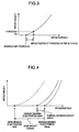
- the braking start position X0 is determined by subtracting a predetermined amount ⁇ X ⁇ from a piston position where the piston thrust F becomes a predetermined threshold value Fth when the braking force is generated or released.
- the braking start position X0 may be a detected value in every detection, or a calculated value based on a plurality of detected values, such as an average detected value based on a number of past detections.
- the drive controller 7 stores three types of braking start positions detected in different times (i.e. a current braking start position X0crnt, an initial braking start position X0init, and a maximum braking start position X0max), and determines a wear amount ⁇ Xwear (hereinafter, referred to simply as a wear amount), and a thermal expansion amount ⁇ Xthrm (hereinafter referred to simply as a thermal expansion amount) of the brake pad 21 on the basis of these braking start positions.
- a wear amount ⁇ Xwear hereinafter, referred to simply as a wear amount
- ⁇ Xthrm hereinafter referred to simply as a thermal expansion amount
- the current braking start position is updated whenever a braking start position is determined by a detection operation. This means that the current braking start position is updated in the shortest period, and shows the latest detected braking start position.
- the maximum braking start position is updated only when a newly detected braking start position is larger than the maximum braking start position stored at that time (which is positive in a wear advance direction), or when the brake pad 21 is replaced. This means that the maximum braking start position shows a braking start position when a detected position is largest in the course of wear on a particular brake pad 21. In addition, the brake pads 21 contract to reduce their thickness as the temperature decreases, so that the braking start position is increased.
- the outside air temperature (approximately -40°C to +40°C) is lower than the temperature of a braked pad (+100°C or higher).
- the maximum braking start position reflects the progress of wear of the brake pads 21, and the braking start position at a low temperature will be detected.
- the braking start position immediately after assembling the brake pads 21 is stored.
- the stored value is updated at the time of producing a product, or at the time of a replacement operation of brake pad replacement.
- the initial braking start position is in an initial state before wear of the brake pads 21 progresses, and is a braking start position when its temperature is equal to the outside air temperature.
- the drive controller 7 estimates the amount of wear and the amount of thermal expansion of the brake pads 21 from the three types of braking start positions detected in different times.
- the amount of wear can be determined from the difference between the initial braking start position and the maximum braking start position.
- Both of the initial braking start position and the maximum braking start position represent the braking start positions at the outside air temperature, and therefore the difference in temperature of the pad at the time of detection has less effect on the difference in thickness of the pad. Accordingly, the difference between the initial braking start position and the maximum braking start position corresponds to the amount of wear of the brake pads 21.
- the amount of thermal expansion is determined from the difference between the current braking start position and the maximum braking start position.
- the current braking start position after braking control may increase in thickness due to the increased temperature of the pads. Since the progressing rate of pad wear is considerably slower than change of the thermal expansion amount, the difference between the current braking start position and the maximum braking start position is considered to be caused by the thermal expansion of the brake pads 21.
- the amount of thermal expansion estimated based on the difference between the maximum braking start position and the current braking start position does not accurately show the amount of thermal expansion at the outside air temperature during braking.
- the amount of thermal expansion at the outside air temperature during braking can be accurately estimated by correcting the difference between the maximum braking start position and the current braking start position depending on the outside air temperature during update.
- an updated value is larger than a value before the update by a predetermined value or more when updating the maximum braking start position, it can be estimated that the position has been updated at a lower outside air temperature than the previous update.
- a state where the difference between the maximum braking start position and the current braking start position is equal to or beyond a predetermined value when updating the current braking start position continues for more than a predetermined number of times, it can be estimated that the maximum braking start position has been updated at a low outside air temperature.
- the outside air temperature during update can be detected directly by an outside air temperature sensor.
- the difference between the maximum braking start position and the current braking start position can be corrected depending on the outside air temperature during update, and the amount of thermal expansion of pads at the outside air temperature during braking can be more accurately determined.
- a method for estimating the amount of thermal expansion and the amount of wear will be described with reference to a flow chart shown in Fig. 1 .
- a threshold value Fth which is a reference value for detecting the braking start position. If a value less than zero is yielded by subtracting the threshold value Fth from each of the thrust sensor value F[t] at the current time t and the thrust sensor value F[t-1] at the previous calculation step and then multiplying the results by each other, it is determined that the piston thrust has passed the threshold value. If it has passed the threshold value, the process proceeds to S2, and otherwise, the process is suspended for a while and resumes the similar processing at the next calculation step.
- a temporary braking start position X0temp is calculated. An average value is determined between the piston position X[t] at the current time t and the piston position X[t-1] at the previous calculation step, from which a predetermined displacement ⁇ X ⁇ is subtracted to yield the temporary braking start position X0temp.
- update is made using the temporary braking start position X0temp as the current braking start position X0crnt.
- determination is made whether the temporary braking start position X0temp is larger than the maximum braking start position X0max, or whether it is immediately after assembling the brake pads. If it is true, the process proceeds to S5, and if not, the process proceeds to S9.
- update is made using the temporary braking start position X0temp as the maximum braking start position X0max.
- determination is made whether it is immediately after assembling the brake pads. If it is true, the process proceeds to S7, and if not, the process proceeds to S8.
- update is made using the temporary braking start position X0temp as the initial braking start position X0init.
- the difference between the initial braking start position X0init and the maximum braking start position X0max is determined as the wear amount ⁇ Xwear, and the process proceeds to S9.
- the difference between the current braking start position X0crnt and the maximum braking start position X0max is determined as the thermal expansion amount ⁇ Xthrm, and the process proceeds to the next calculation step.
- the parking brake operation on the assumption that the braking force decreases due to the thermal contraction can be realized.
- the necessary braking force to deal with the decrease of braking force due to the thermal contraction can be secured by setting the thrust of the piston to be greater than necessary holding braking force. For example, in the case where a current braking start position is different from the maximum braking start position and it is thought that the brake pad 21 is thermally expanded as shown in Fig. 5 , if the braking force is held at point (a), the braking force to be held decreases to point (b) after the pad temperature lowers, and the necessary braking force cannot be secured.
- the amount of thermal expansion can be estimated based on the difference between the current braking start position and the maximum braking start position. If the braking force is held at point (c) by predicting the thermal contraction of the brake pad 21, the braking force can be secured beyond the necessary braking force to be held since the braking force to be held shifts to point (d) after the thermal contraction. In addition, when the amount of thermal expansion is small, by setting a relatively low piston thrust such as the point (d), it becomes unnecessary to set the parking brake with stronger braking force than required, resulting in reduced power consumption and reduced load on the mechanism. Although the braking force to be held has been considered as an object to be controlled in the parking brake operation, a piston position to be held may be considered as an object. In this case, regardless of thermal expansion and thermal contraction, the braking force to be held at the point (d) can be secured by setting the piston position relative to the maximum braking start position.
- the drive controller 7 estimates the temperature, the coefficient of friction, and the rigidity characteristic (the characteristic of the piston thrust with reference to the piston displacement) of the brake pad 21 based on the amount of thermal expansion and the amount of wear of the brake pad 21.
- the drive controller 7 stores the relation among the amount of thermal expansion, the amount of wear, and the pad temperature in advance, and estimates the pad temperature based on the amount of thermal expansion and the amount of wear.
- the pad temperature can be estimated by storing characteristics as shown in Fig. 6-(A) in a theoretical or experimental way. If the wear of the pad progresses, the amount of thermal expansion caused by a certain temperature change relatively becomes small because of the reduction of the pad thickness.
- the coefficient of friction of the brake pad 21 can be estimated by storing the relation between the temperature and the coefficient of friction thereof in advance as shown in Fig. 6-(B) . Since the coefficient of friction of the brake pad 21 varies intricately depending on materials, the characteristic change thereof needs to be determined experimentally. Further, while the rigidity characteristic of the brake pad 21 varies mainly depending on the pad temperature and the amount of wear, the rigidity characteristic of the brake pad 21 can be estimated by storing the relation among the pad temperature, the amount of wear and the rigidity characteristic in advance as shown in Fig. 6-(C) . In Fig.
- 6-(C) , (a) and (b) show rigidity characteristics in the case that the amount of wear is small, in which (a) shows a rigidity characteristic at a low temperature and (b) shows a rigidity characteristic at a high temperature.
- the brake pad 21 becomes soft at a higher temperature, and the increase of the thrust of the piston relating to the piston position becomes milder.
- FIG. 6-(C) , (c) and (d) show rigidity characteristics in the case that the amount of wear is large, in which (c) shows a rigidity characteristic at a low temperature and (d) shows a rigidity characteristic at a high temperature. When the amount of wear is large, the amount of the brake pad to be deformed reduces accordingly.
- the increase of the piston thrust relating to the piston position becomes sharp, and the change of the rigidity characteristic relating to the temperature change becomes small.
- the rigidity characteristic can be estimated.
- the temperature of the brake pad 21 can be estimated, thrust control depending on the change of the coefficient of friction of the pad can be realized.
- a correction gain with respect to a target value of the piston thrust is set in advance so that the change of the coefficient of friction depending on the pad temperature does not affect the deceleration rate of the vehicle.
- the change in deceleration rate of the vehicle due to the change in temperature of the pad can be suppressed by setting the thrust of the piston to be large at such a pad temperature that the coefficient of friction is small, and setting the thrust of the piston to be small at such a pad temperature that the coefficient of friction is large. As shown in Fig.
- Fig. 7-(A) the thrust of the piston is corrected by multiplying a control target value for controlling the thrust of the piston by a correction coefficient having inverted relation to the friction coefficient with respect to the temperature.
- Fig. 7-(B) shows time responses in the case where lowering of the pad temperature is detected at the time of starting the braking control.
- This example assumes the state where the estimated value of the pad temperature is T1 before the piston reaches the braking start position, while the pad temperature lowers to T2 at time t1.
- a pad gap is secured at the time of releasing the brake, and the braking control is started at the time t1.
- the estimated value of the pad temperature is updated to T2 which is lower than T1.
- the time response will be that shown in (a) of Fig. 7-(B) , but since the estimated value of the pad temperature is updated to T2, the time response changes to that shown in (b) of Fig. 7-(B) . Because the coefficient of friction of the brake pad 21 is lower at the temperature T2, the correction gain G2 higher than the correction gain G1 at the temperature T1 is obtained. Accordingly, the rising gradient of the thrust of the piston becomes large, and the convergence value also shifts to F2 which is higher than F1 at temperature T1.
- the rigidity of the pad can be estimated, and the thrust of the piston can be controlled without using a thrust sensor.
- the rigidity of the brake pad 21 decreases as the temperature increase, and increases as the temperature decreases. If the change in the thrust of the piston to the piston position as shown in Fig. 6-(C) is stored in advance, a piston position corresponding to a desired value of the thrust of the piston can be determined, and therefore the piston thrust control can be achieved by performing the feed-back control of the piston displacement without using a thrust sensor.
Applications Claiming Priority (1)
| Application Number | Priority Date | Filing Date | Title |
|---|---|---|---|
| PCT/JP2006/302579 WO2007091337A1 (ja) | 2006-02-08 | 2006-02-08 | 電動ブレーキ装置 |
Publications (3)
| Publication Number | Publication Date |
|---|---|
| EP1985884A1 true EP1985884A1 (de) | 2008-10-29 |
| EP1985884A4 EP1985884A4 (de) | 2009-10-21 |
| EP1985884B1 EP1985884B1 (de) | 2012-10-24 |
Family
ID=38344946
Family Applications (1)
| Application Number | Title | Priority Date | Filing Date |
|---|---|---|---|
| EP06713720A Active EP1985884B1 (de) | 2006-02-08 | 2006-02-08 | Elektrische bremse |
Country Status (5)
| Country | Link |
|---|---|
| US (1) | US8430213B2 (de) |
| EP (1) | EP1985884B1 (de) |
| JP (1) | JP5022915B2 (de) |
| CN (1) | CN101365893B (de) |
| WO (1) | WO2007091337A1 (de) |
Cited By (3)
| Publication number | Priority date | Publication date | Assignee | Title |
|---|---|---|---|---|
| US20140095042A1 (en) * | 2012-09-28 | 2014-04-03 | Hitachi Automotive Systems, Ltd. | Disk brake apparatus |
| EP3044056B1 (de) * | 2013-09-13 | 2019-12-04 | Robert Bosch GmbH | Fahrassistenzsystem mit gesteigerter ausfallsicherheit und verfügbarkeit |
| EP3578429A1 (de) * | 2018-06-06 | 2019-12-11 | Sensata Technologies, Inc. | Verbinder für eine elektromechanische bremse |
Families Citing this family (44)
| Publication number | Priority date | Publication date | Assignee | Title |
|---|---|---|---|---|
| DE102008018749A1 (de) * | 2007-09-12 | 2009-03-26 | Continental Teves Ag & Co. Ohg | Verfahren zum gesicherten Lösen einer elektromechanisch betätigbaren Feststellbremse |
| CN101269770B (zh) * | 2008-05-09 | 2010-06-02 | 上海永大电梯设备有限公司 | 一种实现马达抱闸力侦测的方法 |
| CN101269772B (zh) * | 2008-05-09 | 2013-11-27 | 永大电梯设备(中国)有限公司 | 一种实现马达带闸运行的侦测方法 |
| KR101350845B1 (ko) * | 2009-09-15 | 2014-01-14 | 주식회사 만도 | 전자 브레이크의 간극 조정 장치 및 그 방법 |
| JP5582293B2 (ja) * | 2010-03-31 | 2014-09-03 | 日立オートモティブシステムズ株式会社 | 電動ブレーキ装置 |
| KR101813965B1 (ko) * | 2011-05-16 | 2018-01-02 | 현대모비스 주식회사 | 전동 브레이크 장치의 디스크 패드 간극 제어 방법 |
| JP5637067B2 (ja) * | 2011-05-24 | 2014-12-10 | 株式会社アドヴィックス | 電動ブレーキ装置および電動ブレーキ装置の制御方法 |
| JP5977016B2 (ja) * | 2011-10-26 | 2016-08-24 | Ntn株式会社 | 電動式直動アクチュエータおよび電動ブレーキ装置 |
| GB2499821B (en) * | 2012-02-29 | 2018-12-12 | Bentley Motors Ltd | A braking system for a vehicle |
| US8798846B2 (en) | 2012-04-12 | 2014-08-05 | Toyota Motor Engineering & Manufacturing North America, Inc. | Power limiting system and method based upon brake rotor temperature determination |
| US8924117B2 (en) * | 2012-05-04 | 2014-12-30 | Wabtec Holding Corp. | Brake monitoring system for an air brake arrangement |
| US9020667B2 (en) | 2012-06-11 | 2015-04-28 | Wabtec Holding Corp. | Empty-load device feedback arrangement |
| CN102819870B (zh) * | 2012-08-03 | 2016-04-20 | 无锡市瑞丰精密机电技术有限公司 | 出租汽车计价器整车检定装置的刹车结构 |
| JP6076023B2 (ja) * | 2012-10-12 | 2017-02-08 | Ntn株式会社 | 電動パーキングブレーキ装置及び電動ブレーキ装置 |
| KR102010743B1 (ko) * | 2012-12-05 | 2019-08-14 | 현대모비스 주식회사 | 전자 브레이크 시스템의 초기 위치 판별 방법 |
| FR3003919B1 (fr) * | 2013-03-27 | 2015-04-10 | Messier Bugatti Dowty | Procede de gestion de la duree de vie d'une pile de disques (egalement appelee puits de chaleur) d'un frein d'aeronef |
| ITTO20130307A1 (it) | 2013-04-17 | 2014-10-18 | Itt Italia Srl | Metodo per realizzare un elemento frenante, in particolare una pastiglia freno, sensorizzato, pastiglia freno sensorizzata, impianto frenante di veicolo e metodo associato |
| JP5904182B2 (ja) * | 2013-09-20 | 2016-04-13 | 株式会社アドヴィックス | ブレーキ温度検出装置および電動駐車ブレーキ制御装置 |
| JP6262993B2 (ja) * | 2013-10-31 | 2018-01-17 | 日立オートモティブシステムズ株式会社 | ブレーキ装置 |
| JP6338902B2 (ja) * | 2014-03-24 | 2018-06-06 | Ntn株式会社 | 電動ブレーキ装置および電動ブレーキ装置システム |
| JP6338907B2 (ja) * | 2014-03-27 | 2018-06-06 | Ntn株式会社 | 電動ブレーキ装置 |
| JP6313152B2 (ja) * | 2014-07-18 | 2018-04-18 | Ntn株式会社 | 電動ブレーキ装置 |
| EP2998607A1 (de) * | 2014-09-16 | 2016-03-23 | Meritor Heavy Vehicle Braking Systems (UK) Limited | Verfahren und System zur Einstellung des Laufspiels einer Bremskomponente |
| US9829402B2 (en) | 2015-02-03 | 2017-11-28 | Goodrich Corporation | Actuator system with smart load cell |
| JP6545988B2 (ja) * | 2015-03-26 | 2019-07-17 | Ntn株式会社 | 電動ブレーキ装置 |
| US9511854B2 (en) * | 2015-05-08 | 2016-12-06 | Goodrich Corporation | Load cell gain compensation |
| US9939035B2 (en) | 2015-05-28 | 2018-04-10 | Itt Italia S.R.L. | Smart braking devices, systems, and methods |
| JP6133360B2 (ja) | 2015-06-01 | 2017-05-24 | Ntn株式会社 | 電動ブレーキ装置 |
| JP6418097B2 (ja) * | 2015-07-31 | 2018-11-07 | 株式会社アドヴィックス | 電動駐車制動装置 |
| ITUB20153709A1 (it) | 2015-09-17 | 2017-03-17 | Itt Italia Srl | Dispositivo di analisi e gestione dei dati generati da un sistema frenante sensorizzato per veicoli |
| ITUB20153706A1 (it) * | 2015-09-17 | 2017-03-17 | Itt Italia Srl | Dispositivo frenante per veicolo pesante e metodo di prevenzione del surriscaldamento dei freni in un veicolo pesante |
| JP6465007B2 (ja) * | 2015-12-04 | 2019-02-06 | 株式会社アドヴィックス | 車両の電動制動装置 |
| ITUA20161336A1 (it) | 2016-03-03 | 2017-09-03 | Itt Italia Srl | Dispositivo e metodo per il miglioramento delle prestazioni di un sistema antibloccaggio e antiscivolamento di un veicolo |
| IT201600077944A1 (it) | 2016-07-25 | 2018-01-25 | Itt Italia Srl | Dispositivo per il rilevamento della coppia residua di frenatura in un veicolo equipaggiato con freni a disco |
| DE102017210893A1 (de) * | 2017-06-28 | 2019-01-03 | Robert Bosch Gmbh | Verfahren und eine Vorrichtung zum Betreiben einer automatisierten Feststellbremse |
| KR102006827B1 (ko) * | 2017-09-26 | 2019-10-01 | 주식회사 만도 | 전자식 브레이크 시스템 및 그 제어 방법 |
| DE102018210232A1 (de) * | 2018-06-22 | 2019-12-24 | Robert Bosch Gmbh | Verfahren zum Ansteuern einer elektromechanischen Bremsvorrichtung in einem Fahrzeug |
| HUE058761T2 (hu) * | 2018-09-18 | 2022-09-28 | Knorr Bremse Systeme Fuer Nutzfahrzeuge Gmbh | Fékberendezés hézagának beállítására szolgáló eljárás és fékberendezés |
| DE102018129132B3 (de) * | 2018-11-20 | 2020-01-02 | Knorr-Bremse Systeme für Schienenfahrzeuge GmbH | Verfahren zur Bestimmung eines Bremswegs |
| IT201900015839A1 (it) | 2019-09-06 | 2021-03-06 | Itt Italia Srl | Pastiglia freno per veicoli e suo processo di produzione |
| CN110905951B (zh) * | 2019-12-10 | 2021-11-26 | 深圳鼎然信息科技有限公司 | 动态实时监测汽车刹车片磨损的方法、装置、设备及介质 |
| US11577711B2 (en) * | 2021-03-04 | 2023-02-14 | Akebono Brake Industry Co., Ltd. | Method of controlling a brake for service operation |
| JP2022154643A (ja) * | 2021-03-30 | 2022-10-13 | ナブテスコ株式会社 | ブレーキ装置、摩耗量算出方法、及び摩耗量算出プログラム |
| EP4326586A1 (de) | 2021-05-25 | 2024-02-28 | ITT Italia S.r.l. | Verfahren und vorrichtung zur abschätzung des restdrehmoments zwischen den gebremsten und bremselementen eines fahrzeugs |
Citations (4)
| Publication number | Priority date | Publication date | Assignee | Title |
|---|---|---|---|---|
| JP2003194115A (ja) * | 2001-12-27 | 2003-07-09 | Tokico Ltd | 電動ディスクブレーキおよびその制御プログラム |
| FR2835896A1 (fr) * | 2002-02-12 | 2003-08-15 | Delphi Tech Inc | Dispositif pour detecter un contact entre deux elements de frein d'un systeme de frenage |
| DE10212618A1 (de) * | 2002-03-21 | 2003-10-02 | Lucas Automotive Gmbh | Elektrisch betätigbare Fahrzeugbremse |
| JP2004124950A (ja) * | 2002-07-31 | 2004-04-22 | Tokico Ltd | ブレーキ装置 |
Family Cites Families (16)
| Publication number | Priority date | Publication date | Assignee | Title |
|---|---|---|---|---|
| US4866005A (en) | 1987-10-26 | 1989-09-12 | North Carolina State University | Sublimation of silicon carbide to produce large, device quality single crystals of silicon carbide |
| US4946547A (en) | 1989-10-13 | 1990-08-07 | Cree Research, Inc. | Method of preparing silicon carbide surfaces for crystal growth |
| US5200022A (en) | 1990-10-03 | 1993-04-06 | Cree Research, Inc. | Method of improving mechanically prepared substrate surfaces of alpha silicon carbide for deposition of beta silicon carbide thereon and resulting product |
| US5959316A (en) | 1998-09-01 | 1999-09-28 | Hewlett-Packard Company | Multiple encapsulation of phosphor-LED devices |
| JP2001032868A (ja) | 1999-07-21 | 2001-02-06 | Nissan Motor Co Ltd | 電動ブレーキ装置 |
| JP4482843B2 (ja) | 2000-03-31 | 2010-06-16 | 日立オートモティブシステムズ株式会社 | 電動ディスクブレーキのパッド摩耗の検出方法及び電動ディスクブレーキ装置 |
| US6650044B1 (en) | 2000-10-13 | 2003-11-18 | Lumileds Lighting U.S., Llc | Stenciling phosphor layers on light emitting diodes |
| US20070084682A1 (en) * | 2001-07-31 | 2007-04-19 | Griffith T T | Parking brake adjustment for an aircraft having an electric brake system |
| JP2003175816A (ja) * | 2001-12-13 | 2003-06-24 | Nissan Motor Co Ltd | 電動ブレーキ装置 |
| JP2003194119A (ja) * | 2001-12-28 | 2003-07-09 | Nissan Motor Co Ltd | 電動ブレーキ装置 |
| ES2262985T3 (es) * | 2002-03-21 | 2006-12-01 | Lucas Automotive Gmbh | Freno de vehiculo electricamente accionable y procedimiento para controlar un freno de vehiculo electricamente accionable. |
| JP4137547B2 (ja) | 2002-07-31 | 2008-08-20 | 株式会社日立製作所 | 電動ディスクブレーキ装置 |
| JP4060200B2 (ja) | 2003-02-04 | 2008-03-12 | 日信工業株式会社 | 電気式ディスクブレーキのパッドクリアランス調整方法 |
| JP2005119343A (ja) * | 2003-10-14 | 2005-05-12 | Asmo Co Ltd | 電動駐車ブレーキ装置及びその制御方法 |
| JP2006161899A (ja) * | 2004-12-03 | 2006-06-22 | Honda Motor Co Ltd | 制動装置 |
| EP1845000A3 (de) * | 2006-04-11 | 2010-03-24 | Goodrich Corporation | Steuerung für ein elektromechanisches Bremssystem mit Einstellung des Laufabstands und entsprechendes Verfahren |
-
2006
- 2006-02-08 WO PCT/JP2006/302579 patent/WO2007091337A1/ja active Application Filing
- 2006-02-08 JP JP2007557728A patent/JP5022915B2/ja active Active
- 2006-02-08 US US12/278,764 patent/US8430213B2/en active Active
- 2006-02-08 CN CN2006800525249A patent/CN101365893B/zh active Active
- 2006-02-08 EP EP06713720A patent/EP1985884B1/de active Active
Patent Citations (4)
| Publication number | Priority date | Publication date | Assignee | Title |
|---|---|---|---|---|
| JP2003194115A (ja) * | 2001-12-27 | 2003-07-09 | Tokico Ltd | 電動ディスクブレーキおよびその制御プログラム |
| FR2835896A1 (fr) * | 2002-02-12 | 2003-08-15 | Delphi Tech Inc | Dispositif pour detecter un contact entre deux elements de frein d'un systeme de frenage |
| DE10212618A1 (de) * | 2002-03-21 | 2003-10-02 | Lucas Automotive Gmbh | Elektrisch betätigbare Fahrzeugbremse |
| JP2004124950A (ja) * | 2002-07-31 | 2004-04-22 | Tokico Ltd | ブレーキ装置 |
Non-Patent Citations (1)
| Title |
|---|
| See also references of WO2007091337A1 * |
Cited By (7)
| Publication number | Priority date | Publication date | Assignee | Title |
|---|---|---|---|---|
| US20140095042A1 (en) * | 2012-09-28 | 2014-04-03 | Hitachi Automotive Systems, Ltd. | Disk brake apparatus |
| US9731693B2 (en) * | 2012-09-28 | 2017-08-15 | Hitachi Automotive Systems, Ltd. | Disk brake apparatus |
| EP3044056B1 (de) * | 2013-09-13 | 2019-12-04 | Robert Bosch GmbH | Fahrassistenzsystem mit gesteigerter ausfallsicherheit und verfügbarkeit |
| US10576956B2 (en) | 2013-09-13 | 2020-03-03 | Robert Bosch Gmbh | Driver assistance system with increased reliability and availability |
| EP3044056B2 (de) † | 2013-09-13 | 2024-01-24 | Robert Bosch GmbH | Fahrassistenzsystem mit gesteigerter ausfallsicherheit und verfügbarkeit |
| EP3578429A1 (de) * | 2018-06-06 | 2019-12-11 | Sensata Technologies, Inc. | Verbinder für eine elektromechanische bremse |
| US10744981B2 (en) | 2018-06-06 | 2020-08-18 | Sensata Technologies, Inc. | Electromechanical braking connector |
Also Published As
| Publication number | Publication date |
|---|---|
| JPWO2007091337A1 (ja) | 2009-07-02 |
| WO2007091337A1 (ja) | 2007-08-16 |
| US20090218179A1 (en) | 2009-09-03 |
| EP1985884B1 (de) | 2012-10-24 |
| EP1985884A4 (de) | 2009-10-21 |
| CN101365893A (zh) | 2009-02-11 |
| JP5022915B2 (ja) | 2012-09-12 |
| CN101365893B (zh) | 2011-03-23 |
| US8430213B2 (en) | 2013-04-30 |
Similar Documents
| Publication | Publication Date | Title |
|---|---|---|
| EP1985884B1 (de) | Elektrische bremse | |
| US8833526B2 (en) | Electric brake apparatus | |
| US6238011B1 (en) | Method and device for controlling a wheel brake | |
| KR102133059B1 (ko) | 브레이크 장치 | |
| US8392087B2 (en) | Vehicle control system | |
| US9475471B2 (en) | Braking control apparatus for vehicle | |
| US20070235267A1 (en) | Controller for electromechanical braking system with running clearance adjustment and method | |
| US7140697B2 (en) | Electric parking brake apparatus | |
| KR102006827B1 (ko) | 전자식 브레이크 시스템 및 그 제어 방법 | |
| US20050035653A1 (en) | Electrically actuatable vehicle brake and method for controlling an electrically actuatable vehicle brake | |
| JP2007515344A (ja) | パーキングブレーキとその制御方法 | |
| EP3251908B1 (de) | Bremssystem und verfahren zur steuerung mit luftspaltschätzung | |
| JP5976482B2 (ja) | ブレーキシステム | |
| CN112969618A (zh) | 电动制动器及控制装置 | |
| JP2003175811A (ja) | 電動ブレーキ装置 | |
| EP1416182B1 (de) | Kupplungssteuerung | |
| JP7091576B2 (ja) | 電動パーキングブレーキシステム | |
| JP4941830B2 (ja) | 電動ディスクブレーキ | |
| EP3859184B1 (de) | Elektrische bremse | |
| JP2010006165A (ja) | 電動ディスクブレーキ | |
| US20240092330A1 (en) | Method for controlling the tightening torque of an improved electromechanical brake | |
| US20240083406A1 (en) | Method for operating a brake system of a vehicle, and brake system | |
| JP6906398B2 (ja) | 電動ブレーキ装置 | |
| WO2021087621A1 (en) | Braking system for an off-road vehicle |
Legal Events
| Date | Code | Title | Description |
|---|---|---|---|
| PUAI | Public reference made under article 153(3) epc to a published international application that has entered the european phase |
Free format text: ORIGINAL CODE: 0009012 |
|
| 17P | Request for examination filed |
Effective date: 20080908 |
|
| AK | Designated contracting states |
Kind code of ref document: A1 Designated state(s): DE FR GB IT |
|
| RBV | Designated contracting states (corrected) |
Designated state(s): DE FR GB IT |
|
| A4 | Supplementary search report drawn up and despatched |
Effective date: 20090917 |
|
| 17Q | First examination report despatched |
Effective date: 20100413 |
|
| GRAP | Despatch of communication of intention to grant a patent |
Free format text: ORIGINAL CODE: EPIDOSNIGR1 |
|
| DAX | Request for extension of the european patent (deleted) | ||
| GRAS | Grant fee paid |
Free format text: ORIGINAL CODE: EPIDOSNIGR3 |
|
| GRAA | (expected) grant |
Free format text: ORIGINAL CODE: 0009210 |
|
| AK | Designated contracting states |
Kind code of ref document: B1 Designated state(s): DE FR GB IT |
|
| REG | Reference to a national code |
Ref country code: GB Ref legal event code: FG4D |
|
| REG | Reference to a national code |
Ref country code: DE Ref legal event code: R096 Ref document number: 602006032627 Country of ref document: DE Effective date: 20121213 |
|
| PGFP | Annual fee paid to national office [announced via postgrant information from national office to epo] |
Ref country code: FR Payment date: 20130123 Year of fee payment: 8 Ref country code: GB Payment date: 20130118 Year of fee payment: 8 |
|
| PLBE | No opposition filed within time limit |
Free format text: ORIGINAL CODE: 0009261 |
|
| STAA | Information on the status of an ep patent application or granted ep patent |
Free format text: STATUS: NO OPPOSITION FILED WITHIN TIME LIMIT |
|
| 26N | No opposition filed |
Effective date: 20130725 |
|
| REG | Reference to a national code |
Ref country code: DE Ref legal event code: R097 Ref document number: 602006032627 Country of ref document: DE Effective date: 20130725 |
|
| GBPC | Gb: european patent ceased through non-payment of renewal fee |
Effective date: 20140208 |
|
| REG | Reference to a national code |
Ref country code: FR Ref legal event code: ST Effective date: 20141031 |
|
| PG25 | Lapsed in a contracting state [announced via postgrant information from national office to epo] |
Ref country code: FR Free format text: LAPSE BECAUSE OF NON-PAYMENT OF DUE FEES Effective date: 20140228 Ref country code: GB Free format text: LAPSE BECAUSE OF NON-PAYMENT OF DUE FEES Effective date: 20140208 |
|
| PG25 | Lapsed in a contracting state [announced via postgrant information from national office to epo] |
Ref country code: IT Free format text: LAPSE BECAUSE OF NON-PAYMENT OF DUE FEES Effective date: 20140208 |
|
| PGFP | Annual fee paid to national office [announced via postgrant information from national office to epo] |
Ref country code: DE Payment date: 20221229 Year of fee payment: 18 |