EP1416182B1 - Kupplungssteuerung - Google Patents
Kupplungssteuerung Download PDFInfo
- Publication number
- EP1416182B1 EP1416182B1 EP03078418A EP03078418A EP1416182B1 EP 1416182 B1 EP1416182 B1 EP 1416182B1 EP 03078418 A EP03078418 A EP 03078418A EP 03078418 A EP03078418 A EP 03078418A EP 1416182 B1 EP1416182 B1 EP 1416182B1
- Authority
- EP
- European Patent Office
- Prior art keywords
- clutch
- stroke
- torque
- calculated
- temperature
- Prior art date
- Legal status (The legal status is an assumption and is not a legal conclusion. Google has not performed a legal analysis and makes no representation as to the accuracy of the status listed.)
- Expired - Lifetime
Links
- 230000005540 biological transmission Effects 0.000 claims description 18
- 238000000034 method Methods 0.000 claims description 8
- 230000004044 response Effects 0.000 description 15
- 238000004364 calculation method Methods 0.000 description 6
- 230000008859 change Effects 0.000 description 6
- 230000001419 dependent effect Effects 0.000 description 6
- XLYOFNOQVPJJNP-UHFFFAOYSA-N water Substances O XLYOFNOQVPJJNP-UHFFFAOYSA-N 0.000 description 4
- 238000010586 diagram Methods 0.000 description 3
- 230000004913 activation Effects 0.000 description 2
- 230000003247 decreasing effect Effects 0.000 description 2
- 230000001360 synchronised effect Effects 0.000 description 2
- 238000002485 combustion reaction Methods 0.000 description 1
- 230000000694 effects Effects 0.000 description 1
- 230000006870 function Effects 0.000 description 1
- 239000002184 metal Substances 0.000 description 1
- 238000012986 modification Methods 0.000 description 1
- 230000004048 modification Effects 0.000 description 1
Images


Classifications
-
- F—MECHANICAL ENGINEERING; LIGHTING; HEATING; WEAPONS; BLASTING
- F16—ENGINEERING ELEMENTS AND UNITS; GENERAL MEASURES FOR PRODUCING AND MAINTAINING EFFECTIVE FUNCTIONING OF MACHINES OR INSTALLATIONS; THERMAL INSULATION IN GENERAL
- F16D—COUPLINGS FOR TRANSMITTING ROTATION; CLUTCHES; BRAKES
- F16D48/00—External control of clutches
- F16D48/06—Control by electric or electronic means, e.g. of fluid pressure
-
- B—PERFORMING OPERATIONS; TRANSPORTING
- B60—VEHICLES IN GENERAL
- B60W—CONJOINT CONTROL OF VEHICLE SUB-UNITS OF DIFFERENT TYPE OR DIFFERENT FUNCTION; CONTROL SYSTEMS SPECIALLY ADAPTED FOR HYBRID VEHICLES; ROAD VEHICLE DRIVE CONTROL SYSTEMS FOR PURPOSES NOT RELATED TO THE CONTROL OF A PARTICULAR SUB-UNIT
- B60W2510/00—Input parameters relating to a particular sub-units
- B60W2510/02—Clutches
- B60W2510/0208—Clutch engagement state, e.g. engaged or disengaged
- B60W2510/0225—Clutch actuator position
-
- B—PERFORMING OPERATIONS; TRANSPORTING
- B60—VEHICLES IN GENERAL
- B60W—CONJOINT CONTROL OF VEHICLE SUB-UNITS OF DIFFERENT TYPE OR DIFFERENT FUNCTION; CONTROL SYSTEMS SPECIALLY ADAPTED FOR HYBRID VEHICLES; ROAD VEHICLE DRIVE CONTROL SYSTEMS FOR PURPOSES NOT RELATED TO THE CONTROL OF A PARTICULAR SUB-UNIT
- B60W2510/00—Input parameters relating to a particular sub-units
- B60W2510/02—Clutches
- B60W2510/0291—Clutch temperature
-
- B—PERFORMING OPERATIONS; TRANSPORTING
- B60—VEHICLES IN GENERAL
- B60W—CONJOINT CONTROL OF VEHICLE SUB-UNITS OF DIFFERENT TYPE OR DIFFERENT FUNCTION; CONTROL SYSTEMS SPECIALLY ADAPTED FOR HYBRID VEHICLES; ROAD VEHICLE DRIVE CONTROL SYSTEMS FOR PURPOSES NOT RELATED TO THE CONTROL OF A PARTICULAR SUB-UNIT
- B60W2710/00—Output or target parameters relating to a particular sub-units
- B60W2710/02—Clutches
- B60W2710/021—Clutch engagement state
- B60W2710/022—Clutch actuator position
-
- B—PERFORMING OPERATIONS; TRANSPORTING
- B60—VEHICLES IN GENERAL
- B60W—CONJOINT CONTROL OF VEHICLE SUB-UNITS OF DIFFERENT TYPE OR DIFFERENT FUNCTION; CONTROL SYSTEMS SPECIALLY ADAPTED FOR HYBRID VEHICLES; ROAD VEHICLE DRIVE CONTROL SYSTEMS FOR PURPOSES NOT RELATED TO THE CONTROL OF A PARTICULAR SUB-UNIT
- B60W2710/00—Output or target parameters relating to a particular sub-units
- B60W2710/02—Clutches
- B60W2710/027—Clutch torque
-
- F—MECHANICAL ENGINEERING; LIGHTING; HEATING; WEAPONS; BLASTING
- F16—ENGINEERING ELEMENTS AND UNITS; GENERAL MEASURES FOR PRODUCING AND MAINTAINING EFFECTIVE FUNCTIONING OF MACHINES OR INSTALLATIONS; THERMAL INSULATION IN GENERAL
- F16D—COUPLINGS FOR TRANSMITTING ROTATION; CLUTCHES; BRAKES
- F16D2500/00—External control of clutches by electric or electronic means
- F16D2500/10—System to be controlled
- F16D2500/102—Actuator
- F16D2500/1021—Electrical type
- F16D2500/1023—Electric motor
-
- F—MECHANICAL ENGINEERING; LIGHTING; HEATING; WEAPONS; BLASTING
- F16—ENGINEERING ELEMENTS AND UNITS; GENERAL MEASURES FOR PRODUCING AND MAINTAINING EFFECTIVE FUNCTIONING OF MACHINES OR INSTALLATIONS; THERMAL INSULATION IN GENERAL
- F16D—COUPLINGS FOR TRANSMITTING ROTATION; CLUTCHES; BRAKES
- F16D2500/00—External control of clutches by electric or electronic means
- F16D2500/10—System to be controlled
- F16D2500/104—Clutch
- F16D2500/10406—Clutch position
- F16D2500/10412—Transmission line of a vehicle
-
- F—MECHANICAL ENGINEERING; LIGHTING; HEATING; WEAPONS; BLASTING
- F16—ENGINEERING ELEMENTS AND UNITS; GENERAL MEASURES FOR PRODUCING AND MAINTAINING EFFECTIVE FUNCTIONING OF MACHINES OR INSTALLATIONS; THERMAL INSULATION IN GENERAL
- F16D—COUPLINGS FOR TRANSMITTING ROTATION; CLUTCHES; BRAKES
- F16D2500/00—External control of clutches by electric or electronic means
- F16D2500/10—System to be controlled
- F16D2500/104—Clutch
- F16D2500/10443—Clutch type
- F16D2500/1045—Friction clutch
-
- F—MECHANICAL ENGINEERING; LIGHTING; HEATING; WEAPONS; BLASTING
- F16—ENGINEERING ELEMENTS AND UNITS; GENERAL MEASURES FOR PRODUCING AND MAINTAINING EFFECTIVE FUNCTIONING OF MACHINES OR INSTALLATIONS; THERMAL INSULATION IN GENERAL
- F16D—COUPLINGS FOR TRANSMITTING ROTATION; CLUTCHES; BRAKES
- F16D2500/00—External control of clutches by electric or electronic means
- F16D2500/10—System to be controlled
- F16D2500/108—Gear
- F16D2500/1081—Actuation type
- F16D2500/1083—Automated manual transmission
-
- F—MECHANICAL ENGINEERING; LIGHTING; HEATING; WEAPONS; BLASTING
- F16—ENGINEERING ELEMENTS AND UNITS; GENERAL MEASURES FOR PRODUCING AND MAINTAINING EFFECTIVE FUNCTIONING OF MACHINES OR INSTALLATIONS; THERMAL INSULATION IN GENERAL
- F16D—COUPLINGS FOR TRANSMITTING ROTATION; CLUTCHES; BRAKES
- F16D2500/00—External control of clutches by electric or electronic means
- F16D2500/30—Signal inputs
- F16D2500/302—Signal inputs from the actuator
- F16D2500/3026—Stroke
-
- F—MECHANICAL ENGINEERING; LIGHTING; HEATING; WEAPONS; BLASTING
- F16—ENGINEERING ELEMENTS AND UNITS; GENERAL MEASURES FOR PRODUCING AND MAINTAINING EFFECTIVE FUNCTIONING OF MACHINES OR INSTALLATIONS; THERMAL INSULATION IN GENERAL
- F16D—COUPLINGS FOR TRANSMITTING ROTATION; CLUTCHES; BRAKES
- F16D2500/00—External control of clutches by electric or electronic means
- F16D2500/30—Signal inputs
- F16D2500/304—Signal inputs from the clutch
- F16D2500/30402—Clutch friction coefficient
-
- F—MECHANICAL ENGINEERING; LIGHTING; HEATING; WEAPONS; BLASTING
- F16—ENGINEERING ELEMENTS AND UNITS; GENERAL MEASURES FOR PRODUCING AND MAINTAINING EFFECTIVE FUNCTIONING OF MACHINES OR INSTALLATIONS; THERMAL INSULATION IN GENERAL
- F16D—COUPLINGS FOR TRANSMITTING ROTATION; CLUTCHES; BRAKES
- F16D2500/00—External control of clutches by electric or electronic means
- F16D2500/30—Signal inputs
- F16D2500/304—Signal inputs from the clutch
- F16D2500/30404—Clutch temperature
- F16D2500/30405—Estimated clutch temperature
-
- F—MECHANICAL ENGINEERING; LIGHTING; HEATING; WEAPONS; BLASTING
- F16—ENGINEERING ELEMENTS AND UNITS; GENERAL MEASURES FOR PRODUCING AND MAINTAINING EFFECTIVE FUNCTIONING OF MACHINES OR INSTALLATIONS; THERMAL INSULATION IN GENERAL
- F16D—COUPLINGS FOR TRANSMITTING ROTATION; CLUTCHES; BRAKES
- F16D2500/00—External control of clutches by electric or electronic means
- F16D2500/50—Problem to be solved by the control system
- F16D2500/502—Relating the clutch
- F16D2500/50245—Calibration or recalibration of the clutch touch-point
- F16D2500/50266—Way of detection
- F16D2500/50275—Estimation of the displacement of the clutch touch-point due to the modification of relevant parameters, e.g. temperature, wear
-
- F—MECHANICAL ENGINEERING; LIGHTING; HEATING; WEAPONS; BLASTING
- F16—ENGINEERING ELEMENTS AND UNITS; GENERAL MEASURES FOR PRODUCING AND MAINTAINING EFFECTIVE FUNCTIONING OF MACHINES OR INSTALLATIONS; THERMAL INSULATION IN GENERAL
- F16D—COUPLINGS FOR TRANSMITTING ROTATION; CLUTCHES; BRAKES
- F16D2500/00—External control of clutches by electric or electronic means
- F16D2500/70—Details about the implementation of the control system
- F16D2500/702—Look-up tables
- F16D2500/70205—Clutch actuator
- F16D2500/70235—Displacement
-
- F—MECHANICAL ENGINEERING; LIGHTING; HEATING; WEAPONS; BLASTING
- F16—ENGINEERING ELEMENTS AND UNITS; GENERAL MEASURES FOR PRODUCING AND MAINTAINING EFFECTIVE FUNCTIONING OF MACHINES OR INSTALLATIONS; THERMAL INSULATION IN GENERAL
- F16D—COUPLINGS FOR TRANSMITTING ROTATION; CLUTCHES; BRAKES
- F16D2500/00—External control of clutches by electric or electronic means
- F16D2500/70—Details about the implementation of the control system
- F16D2500/704—Output parameters from the control unit; Target parameters to be controlled
- F16D2500/70402—Actuator parameters
- F16D2500/7041—Position
-
- F—MECHANICAL ENGINEERING; LIGHTING; HEATING; WEAPONS; BLASTING
- F16—ENGINEERING ELEMENTS AND UNITS; GENERAL MEASURES FOR PRODUCING AND MAINTAINING EFFECTIVE FUNCTIONING OF MACHINES OR INSTALLATIONS; THERMAL INSULATION IN GENERAL
- F16D—COUPLINGS FOR TRANSMITTING ROTATION; CLUTCHES; BRAKES
- F16D2500/00—External control of clutches by electric or electronic means
- F16D2500/70—Details about the implementation of the control system
- F16D2500/704—Output parameters from the control unit; Target parameters to be controlled
- F16D2500/70422—Clutch parameters
- F16D2500/70438—From the output shaft
- F16D2500/7044—Output shaft torque
-
- F—MECHANICAL ENGINEERING; LIGHTING; HEATING; WEAPONS; BLASTING
- F16—ENGINEERING ELEMENTS AND UNITS; GENERAL MEASURES FOR PRODUCING AND MAINTAINING EFFECTIVE FUNCTIONING OF MACHINES OR INSTALLATIONS; THERMAL INSULATION IN GENERAL
- F16D—COUPLINGS FOR TRANSMITTING ROTATION; CLUTCHES; BRAKES
- F16D2500/00—External control of clutches by electric or electronic means
- F16D2500/70—Details about the implementation of the control system
- F16D2500/704—Output parameters from the control unit; Target parameters to be controlled
- F16D2500/70464—Transmission parameters
- F16D2500/70466—Input shaft
- F16D2500/70468—Input shaft torque
-
- F—MECHANICAL ENGINEERING; LIGHTING; HEATING; WEAPONS; BLASTING
- F16—ENGINEERING ELEMENTS AND UNITS; GENERAL MEASURES FOR PRODUCING AND MAINTAINING EFFECTIVE FUNCTIONING OF MACHINES OR INSTALLATIONS; THERMAL INSULATION IN GENERAL
- F16D—COUPLINGS FOR TRANSMITTING ROTATION; CLUTCHES; BRAKES
- F16D2500/00—External control of clutches by electric or electronic means
- F16D2500/70—Details about the implementation of the control system
- F16D2500/706—Strategy of control
- F16D2500/7061—Feed-back
Definitions
- This invention generally relates to a clutch control device configured to change an engaged condition between a clutch disc and a flywheel by controlling activation of an actuator.
- a system which automatically performs a series of gear ratio change operations including a clutch engaging or disengaging operation, a gear select operation, and a gear shift operation.
- the series of gear ratio change operations is performed for example by use of an actuator for a conventional manual transmission in response to vehicle driving conditions or a driver's intention.
- the system controls a torque transmitted between a flywheel and a clutch disc by controlling actuation of a clutch actuator.
- the torque transmitted therebetween is referred to as a clutch torque.
- An optimal clutch operation can be hence performed in response to vehicle driving conditions by controlling the clutch torque imposed by the actuator.
- the clutch torque is actually controlled by controlling pressure load on the clutch disc relative to the flywheel by the actuator. That is, the clutch torque substantially corresponds to a value calculated by multiplying the pressure load on the clutch disc relative to the flywheel by a friction coefficient ⁇ . Therefore, the control of the pressure load by the actuator can be practically considered as the control of the clutch torque.
- EP-A-460628 discloses a clutch control system which takes the clutch disc temperature into account. Either only below a measured or calculated clutch disc temperature (T>K) or for all clutch disc temperatures a control algorithm is used which for increasing clutch temperatures moves the assumed position of initial contact between the clutch plate and flywheel progressively towards the last recorded position of initial contact.
- the Applicants have verified the manner in which the friction coefficient ⁇ fluctuates in response to the temperature of the clutch disc - i.e., a clutch temperature. That is illustrated in FIG. 4 of this specification. For example, when the clutch temperature is relatively high, the friction coefficient ⁇ is reduced. In this case, the actual clutch torque will be less than the intended clutch torque even if the pressure load has been controlled at a desired load value by the actuator.
- the invention provides a method of controlling the transmission of a clutch torque having the characterisitics of claim 1 herein.
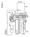
- a vehicle control system includes main elements such as an engine (a driving power source) 10. an automatic clutch assembly 20, an automated manual transmission 30, and an electronic control unit (ECU, a controller) 50.
- the automatic clutch assembly 20 incorporates a flywheel 10a configured to rotate integrally with a crankshaft - i.e., an output shaft of an internal combustion engine such as an engine 10.
- the automated manual transmission 30 is operatively linked to the engine 10 via the automatic clutch assembly 20.
- the engine 10 is provided with an ignition switch 11 for an engine ignition, an engine rotational speed sensor 16 for detecting rotational speed of the crankshaft Ne, and an engine water temperature sensor 17 for detecting engine water temperature Tw.
- Each of the ignition switch 11, the sensors 16 and 17 may be mounted on the engine 10 or may be mounted somewhere in the vehicle as illustrated in FIG. 1 .
- the automatic clutch assembly 20 includes a mechanical (dry type - single) friction clutch 21, a clutch lever 22, and an actuator 23 configured to control clutch torque by use of the clutch lever 22.
- the friction clutch 21 includes a clutch disc 21a which is disposed facing the flywheel 10a and is rotatable integrally with an input shaft 31 of the automated manual transmission 30.
- clutch torquetransmitted between the flywheel 10a and the clutch disc 21a varies in response to the change of the pressure load
- the rotational speed transmitted between the flywheel 10a and the clutch disc 21 a substantially corresponds to rotational speed transmitted between the output shaft of the engine 10 and the input shaft 31 of the automated manual transmission 30 and is a product of transmitted clutch torque.
- the clutch actuator 23 is provided with a direct current electric motor 24 as a driving power source.
- the clutch lever 22 varies its posture in response to forward or rearward movement of a rod 25 operated by the motor 24.
- a diaphragm spring 28 is made of a resilient metal and can be contacted by a release bearing 27 operated by the clutch lever 22.
- a pressure plate 29 in the friction clutch 21 is applied with pressure load from the distorted diaphragm spring 28 which is supported by clutch cover 21b at a fulcrum.
- the pressure plate 29 is mounted an a clutch cover 21b of the friction clutch 21 which is integrally rotatable with the flywheel 10a.
- the slip amount will ultimately become zero in response to an increase of the pressure load along with the retraction of the rod 25, at which stage the flywheel 10a and the clutch disc 21a are synchronized for rotation.
- the synchronized rotation of the flywheel 10a and the clutch disc 21a is referred to as a clutch fully engaged condition.
- the position of the rod 25 at this point is referred to as a fully engaged position. Therefore.
- the slip amount between the flywheel 10a and the clutch disc 21a varies by controlling the stroke of the rod 25 by the clutch actuator 23 between the standby position and the clutch fully engaged position.
- the condition of the flywheel 10a and the clutch disc 21a is referred to as a clutch half-engaged condition.
- the clutch fully engaged condition and the clutch half-engaged condition both represent clutch engaged conditions.
- FIG. 3 is a diagram for explaining a basic relationship of the clutch torque relative to the clutch stroke of the rod 25.
- a zero point of the clutch stroke corresponds to the standby position.
- the clutch stroke at the right-hand side of the Zero Point corresponds to the moving amount of the rod 25 in the direction of the fully engaged position.
- the clutch torque represents torque which can be transmitted from the flywheel 10a to the clutch disc 21a by engagement.
- the clutch torque is increased in response to the increase of the clutch stroke.
- the vehicle can be smoothly and accurately accelerated by controlling the clutch torque in response to the vehicle driving conditions.
- the automatic clutch assembly 20 is provided with a stroke sensor 26 for detecting a clutch stroke St which represents a moving position of the rod 25.
- the clutch stroke St is relied on for judging a condition for the rotation transmitted via the friction clutch 21.
- the stroke ⁇ sensor 26 may be mounted on the rod 25 or may be mounted elsewhere in the vehicle as illustrated in FIG. 1 .
- the automated manual transmission 30 is a parallel axis type gear transmission which performs for example, five forward shift stages and a single reverse shift stage.
- the automated manual transmission 30 includes the input shaft 31, an output shaft 32, and plural gear trains for speed change.
- the input shaft 31 of the transmission 30 is linked to the clutch disc 21a of the friction clutch 21 such that the driving force from the engine 10 can be transmitted to the transmission 30 via the input shaft 31.
- the output shaft 32 of the transmission 30 is operatively linked to an axle (not shown).
- a rotational speed sensor 33 illustrated in FIG. 1 is provided for detecting the rotational speed of the input shaft 31 - i.e., an input shaft rotational speed Ni.
- the rotational speed sensor 33 may be mounted on the input shaft 31 or may be mounted elsewhere in the vehicle.
- a shift actuator 41 illustrated in FIG. 1 is provided for selecting gear trains for transmitting the driving-power from the engine 10.
- the shift actuator 41 may be disposed in the transmission 30 or elsewhere in the vehicle.
- the automated manual transmission 30 can hence perform a desired shift stage therein in response to activation of the shift actuator 41.
- the vehicle control system illustrated in FIG. 1 is provided with the electronic control unit (ECU) 50 which functions for example as estimating means and correcting means.
- the ECU 50 includes main elements such as a well-known central processing unit (CPU) with a microcomputer, a read-only-memory (ROM) for memorizing various programs and maps, a random-access-memory (RAM) for reading out and writing down various data, and an electronically erasable and programmable read only memory (EEPROM) for storing data without a back-up power source.
- the ECU 50 is connected with ignition switch 11, various sensors including the engine rotational speed sensor 16, the engine water temperature sensor 17, the stroke sensor 26, and the rotational speed sensor 33, the clutch actuator 23, and the shift actuator 41.
- the ECU 50 receives as inputs the on signal from the ignition switch 11 and signals detected by various sensors so as to detect the vehicle driving condition including the on/off condition of the ignition switch 11, the engine rotational speed Ne, the engine water temperature Tw, the clutch stroke St, the input shaft rotational speed Ni, and the like.
- the ECU 50 further activates the clutch actuator 23 and the shift actuator 41 based upon the vehicle driving conditions.
- the ECU 50 activates the clutch actuator 23 for adjusting the rotational speed transmitted via the friction clutch 21. Therefore, the rotational speed transmitted can be automatically controlled depending on the vehicle driving conditions. Further, the ECU 50 activates the shift actuator 41 for selecting the gear train capable of transmitting the driving power in the transmission 30. Therefore, the rotational speed change can be automatically performed in the transmission 30 in response to the vehicle driving conditions.
- the following description explains the clutch control according to this embodiment of the present invention with reference to a flowchart illustrated in FIG. 2 .
- the clutch control calculations are repeatedly performed at fixed time intervals whenever the ignition switch 11 is turned on.
- the ECU 50 first starts a main routine at step 101 for calculating a reference target clutch torque. That is, the ECU 50 calculates a reference target clutch torque TMB for properly performing the clutch control in response to the vehicle driving conditions based upon the signals detected by the various sensors.
- the reference target clutch torque TMB represents a target clutch torque calculated on the assumption that the clutch disc 21a is at a predetermined reference temperature.
- the ECU 50 then proceeds to step 200, in which a temperature-dependent correction coefficient for clutch torque is calculated.
- the friction coefficient ⁇ is gradually decreased.
- the basic relationship between the clutch torque and the clutch stroke illustrated in FIG. 3 corresponds to clutch temperatures below the critical temperature.
- the clutch load (the pressure load on the clutch disc 21a) can be estimated based upon the clutch stroke, and the resulting clutch torque can be estimated by multiplying the clutch load by the friction coefficient ⁇ .
- the relationship of the clutch torque relative to the clutch stroke is a linear relationship if the friction coefficient ⁇ is constant.
- a correction coefficient depending on clutch temperature can effectively absorb influences on the actual clutch torque due to variation of the friction coefficient ⁇ in order to reduce the difference from the relationship illustrated in FIG.
- the correction coefficient which is temperature dependent, is used to calculate an increased target clutch torque. That increased target clutch torque, coupled with the lower friction coefficient ⁇ , is effective to achieve in practice the intended clutch torque. In this way, compensation for decrease of the clutch torque relative to the clutch stroke - i.e., relative to the clutch load, is conducted.
- the ECU 50 performs a subroutine at step 200 after calculation of the temperature dependent correction coefficient.
- a clutch estimated temperature Tc(n) estimated through a procedure at this time is updated as a clutch estimated temperature buffer Tc(n-1).
- the clutch estimated temperature buffer Tc(n-1) is read at a procedure at the next time and is applied for estimating the clutch temperature.
- the ECU 50 proceeds to step 102 for calculating a target clutch torque TM.
- the target clutch torque TM is calculated by multiplying the reference target clutch torque TMB calculated at step 101 by the temperature dependent correction coefficient.
- the ECU 50 then proceeds to step 103 for calculating a target clutch stroke. More particularly, The ECU 50 calculates at step 103 a target clutch stroke corresponding to the target clutch torque TM calculated based upon the relationship illustrated in FIG. 3 .
- the ECU 50 performs a feedback control so as to substantially match the detected clutch stroke St with the calculated target clutch stroke.
- the main routine is here temporarily terminated.
- the target clutch torque, and thus the target clutch stroke is corrected based upon the estimated clutch temperature. That is, the target clutch torque, and thus the target clutch stroke, is corrected so as to absorb fluctuations of the friction coefficient ⁇ of the clutch disc based on the estimated clutch temperature. Therefore, the system performs the feedback control for adjusting the actual clutch torque to the target clutch torque.
- the clutch torque is controlled by the clutch actuator 23 which operates the clutch lever 22 along with the movement of the rod 25.
- the clutch torque can be controlled by a clutch actuator which operates the release bearing 27, the diaphragm spring 28, or the pressure plate 29 directly.
- the clutch temperature can be estimated in response to the vehicle driving conditions.
- the clutch temperature can be estimated by a sensor for detecting a temperature of the clutch disc 21a.
- the temperature dependent correction coefficient for the clutch torque is applied to correct the actual clutch torque in light of the influence due to changes in the friction coefficient ⁇ .
- a temperature dependent correction coefficient for the clutch torque could be applied to correct the actual clutch torque in light of the influence due to thermal expansion of the clutch disc 21a, the rod 25, the clutch lever 22, the release bearing 27, the diaphragm spring 28, and the pressure plate 29.
- the target clutch stroke of the rod 25 is calculated based upon the target clutch torque TM which is obtained by correcting the reference target clutch torque TMB.
- the actual clutch stroke is changed through the feedback control based upon the target clutch stroke.
- a reference target clutch stroke can be calculated based upon the reference target clutch torque.
- the actual clutch stroke is changed through a feedback control based upon the target clutch stroke which is obtained by correcting the reference target clutch stroke.
- a variety of these calculations are yielded simply in accordance with a variety of calculating orders. Therefore, these calculations can be substantially counted as equivalent calculations.
- the target clutch stroke or the target clutch torque can be calculated by various calculating methods which are fully equivalent to the calculations described above in accordance with the relationship illustrated in FIG. 3 .
Landscapes
- Engineering & Computer Science (AREA)
- General Engineering & Computer Science (AREA)
- Physics & Mathematics (AREA)
- Fluid Mechanics (AREA)
- Mechanical Engineering (AREA)
- Hydraulic Clutches, Magnetic Clutches, Fluid Clutches, And Fluid Joints (AREA)
Claims (4)
- Verfahren zur Steuerung der Übertragung eines Kupplungsmoments zwischen einem Schwungrad (10a) und einer Kupplungsscheibe (21 a) durch Steuerung des Kupplungswegs einer Kupplungsbetätigung (23), dadurch gekennzeichnet, dass
ein Referenz-Soll-Kupplungsmoment (TMB) bei einer vorbestimmten Referenztemperatur berechnet wird (Schritt 101);
eine Kupplungstemperatur (Tc(n)) bei der Kupplungsscheibe (21 a) gemessen oder berechnet wird (Schritt 200);
ein Reibungskoeffizient (µ) zwischen dem Schwungrad (10a) und der Kupplungsscheibe (21a) bei der gemessenen oder abgeschätzten Kupplungstemperatur (Tc(n)) berechnet wird (Schritt 200);
ein Soll-Kupplungsmoment (TM) durch Multiplizieren des Referenz-Soll-Kupplungsmoments (TMB) mit dem berechneten Reibungskoeffizienten (µ) berechnet wird (Schritt 102);
ein Soll-Kupplungsweg berechnet wird (Schritt 103), der der Kupplungsweg ist, der zum Erreichen des Soll-Kupplungsmoments (TM) bei der vorbestimmten Referenztemperatur (Tc(n)) notwendig wäre; und
die Kupplungsbetätigung (23) gemäß dem berechneten Soll-Kupplungsweg betrieben wird, mit Feedback von der Kupplungsbetätigung (23), die zum Bestätigen verwendet wird, dass der in der Praxis erreichte Kupplungsweg (St) dser Gleiche wie der berechnete Soll-Kupplungsweg ist (Schritt 104). - Verfahren gemäß Anspruch 1, wobei die vorbestimmte Referenztemperatur (Tc(n)), bei der das Referenz-Soll-Kupplungsmoment (TMB) berechnet wird, eine Temperatur ist, bei der der Reibungskoeffizient zwischen dem Schwungrad (10a) und der Kupplungsscheibe (21a) nicht signifikant von den Temperaturschwankungen der Kupplungsscheibe (21 a) abweicht.
- Verfahren nach Anspruch 1 oder 2, wobei der berechnete Reibungskoeffizient (µ) von einer Nachschlagetabelle aus einem Speicher erhalten wird.
- Verfahren gemäß einem der Ansprüche 1 bis 3, wobei der Soll-Kupplungsweg von einer Karte, die auf einem vorbestimmten Verhältnis zwischen dem Kupplungsweg und dem resultierenden Kupplungsmoment bei einer vorbestimmten Temperatur basiert, berechnet wird.
Applications Claiming Priority (2)
| Application Number | Priority Date | Filing Date | Title |
|---|---|---|---|
| JP2002315863 | 2002-10-30 | ||
| JP2002315863A JP2004150513A (ja) | 2002-10-30 | 2002-10-30 | クラッチ制御装置 |
Publications (3)
| Publication Number | Publication Date |
|---|---|
| EP1416182A2 EP1416182A2 (de) | 2004-05-06 |
| EP1416182A3 EP1416182A3 (de) | 2005-03-23 |
| EP1416182B1 true EP1416182B1 (de) | 2011-11-23 |
Family
ID=32089528
Family Applications (1)
| Application Number | Title | Priority Date | Filing Date |
|---|---|---|---|
| EP03078418A Expired - Lifetime EP1416182B1 (de) | 2002-10-30 | 2003-10-30 | Kupplungssteuerung |
Country Status (2)
| Country | Link |
|---|---|
| EP (1) | EP1416182B1 (de) |
| JP (1) | JP2004150513A (de) |
Families Citing this family (13)
| Publication number | Priority date | Publication date | Assignee | Title |
|---|---|---|---|---|
| EP1610017A1 (de) * | 2004-06-21 | 2005-12-28 | LuK Lamellen und Kupplungsbau Beteiligungs KG | Drehmomentübertragungseinrichtung und Antriebstrang mit dieser |
| JP4715132B2 (ja) * | 2004-08-25 | 2011-07-06 | アイシン精機株式会社 | クラッチ制御装置 |
| FR2882118B1 (fr) * | 2005-02-15 | 2007-06-22 | Peugeot Citroen Automobiles Sa | Procede et systeme d'asservissement d'un embrayage pilote et procede de fabrication du systeme |
| JP4550612B2 (ja) * | 2005-02-18 | 2010-09-22 | 日立オートモティブシステムズ株式会社 | 車両用歯車式変速機の制御装置,制御方法及び制御システム |
| DE502005006276D1 (de) | 2005-07-06 | 2009-01-29 | Getrag Ford Transmissions Gmbh | Verfahren zur Bestimmung der Temperatur einer Reibkupplung |
| FR2907867B1 (fr) * | 2006-10-25 | 2009-07-03 | Peugeot Citroen Automobiles Sa | Systeme et procede d'estimation d'un couple transmis par un embrayage a friction de vehicule automobile |
| FR2912792B1 (fr) * | 2007-02-16 | 2009-04-24 | Peugeot Citroen Automobiles Sa | Procede et dispositif de pilotage de l'organe de couplage d'une transmission de vehicule automobile |
| FR2933913B1 (fr) * | 2008-07-16 | 2011-01-14 | Renault Sas | Dispositif de commande adaptative a l'evolution de la caracteristique d'un embrayage en fonction de la temperature applique a un vehicule equipe d'un systeme 4x4 pilote. |
| DE102008042639A1 (de) * | 2008-10-07 | 2010-04-08 | Robert Bosch Gmbh | Bestimmung einer Kupplungstemperatur einer Reibkupplung in einem Kraftfahrzeug |
| WO2010128276A1 (en) * | 2009-05-02 | 2010-11-11 | Raicam Clutch Limited | Vehicle driveline including clutches |
| GB2470015B (en) * | 2009-05-05 | 2016-05-18 | Gm Global Tech Operations Llc | Method and apparatus for estimating clutch friction |
| JP6260202B2 (ja) * | 2013-10-31 | 2018-01-17 | アイシン精機株式会社 | 動力伝達装置およびクラッチ駆動制御装置 |
| CN114941666A (zh) * | 2022-04-02 | 2022-08-26 | 潍柴动力股份有限公司 | 离合器控制方法、装置、电子设备和存储介质 |
Family Cites Families (6)
| Publication number | Priority date | Publication date | Assignee | Title |
|---|---|---|---|---|
| JPH0446224A (ja) * | 1990-06-06 | 1992-02-17 | Zexel Corp | クラッチ操作制御用データの補正方法 |
| DE19641074C2 (de) * | 1996-10-04 | 2003-12-04 | Zf Batavia Llc | Verfahren zur Temperaturbestimmung einer Reibschlußverbindung |
| NO981839L (no) * | 1997-04-30 | 1998-11-02 | Luk Getriebe Systeme Gmbh | Anordning for styring av et dreiemomentoverf°ringssystem |
| DE10045758A1 (de) * | 2000-09-15 | 2002-03-28 | Bosch Gmbh Robert | Verfahren und Einrichtung zum Betrieb einer Kupplung |
| KR100466380B1 (ko) * | 2000-09-19 | 2005-01-13 | 닛산 지도우샤 가부시키가이샤 | 클러치 온도 추정 장치 및 방법 |
| DE10155459B4 (de) * | 2000-11-27 | 2017-06-08 | Schaeffler Technologies AG & Co. KG | Kraftfahrzeug |
-
2002
- 2002-10-30 JP JP2002315863A patent/JP2004150513A/ja active Pending
-
2003
- 2003-10-30 EP EP03078418A patent/EP1416182B1/de not_active Expired - Lifetime
Also Published As
| Publication number | Publication date |
|---|---|
| EP1416182A3 (de) | 2005-03-23 |
| JP2004150513A (ja) | 2004-05-27 |
| EP1416182A2 (de) | 2004-05-06 |
Similar Documents
| Publication | Publication Date | Title |
|---|---|---|
| EP1630442B1 (de) | Kupplungssteuerungsvorrichtung | |
| EP0616142B1 (de) | Berührpunkt-Erkennungsverfahren einer Kupplung | |
| EP1416182B1 (de) | Kupplungssteuerung | |
| US8645036B2 (en) | Method for controlling a clutch unit | |
| KR100509674B1 (ko) | 자동차의자동화클러치가토크전달을시작하는맞물림지점을측정하여자동화클러치의토크전달을자동으로제어하는방법및자동차 | |
| US6050379A (en) | Algorithm for electro-mechanical clutch actuator | |
| EP1559923B1 (de) | Kupplungssteuervorrichtung | |
| US5029678A (en) | Automatic clutch control apparatus | |
| US4678069A (en) | Clutch control system with variable clutch connection position | |
| US5307269A (en) | Method for correcting clutch control data in accordance with disk temperature | |
| US8131438B2 (en) | Method for controlling an automated friction clutch | |
| US7424356B2 (en) | Method and device for referencing an incremental travel sensor in an electronically controlled actuation device of a clutch | |
| US5993352A (en) | Clutch assembly with control device which determines adapted gripping point and gradient of clutch characteristic curve | |
| US8660766B2 (en) | Method for computational determination of the oil temperature in a clutch unit | |
| US7658261B2 (en) | Drive train for a motor vehicle and method for operating such a drive train | |
| US6001044A (en) | Motor vehicle | |
| EP2686571B1 (de) | Verfahren und system zur bestimmung der notwendigkeit einer kontaktpunktanpassung | |
| EP1411262B1 (de) | Kupplungssteuerungseinrichtung | |
| EP0460628B1 (de) | Verfahren für die Korrektur von Daten, die für eine Kupplungssteuerung verwendet werden | |
| US20120053801A1 (en) | Method and apparatus for estimating clutch friction coefficient | |
| EP0461578B1 (de) | Verfahren zur Korrektur von Daten, die für die Steuerung einer Fahrzeugkupplung verwendet werden | |
| EP1184607B1 (de) | Steuerungseinrichtung einer Stelleinrichtung für den Einsatz in einer Getriebeeinheit | |
| EP1384912B1 (de) | Kupplungssteuerungvorrichtung | |
| JP2008185217A (ja) | クラッチ制御装置 | |
| JP2005273875A (ja) | クラッチ制御装置 |
Legal Events
| Date | Code | Title | Description |
|---|---|---|---|
| PUAI | Public reference made under article 153(3) epc to a published international application that has entered the european phase |
Free format text: ORIGINAL CODE: 0009012 |
|
| AK | Designated contracting states |
Kind code of ref document: A2 Designated state(s): AT BE BG CH CY CZ DE DK EE ES FI FR GB GR HU IE IT LI LU MC NL PT RO SE SI SK TR |
|
| AX | Request for extension of the european patent |
Extension state: AL LT LV MK |
|
| PUAL | Search report despatched |
Free format text: ORIGINAL CODE: 0009013 |
|
| AK | Designated contracting states |
Kind code of ref document: A3 Designated state(s): AT BE BG CH CY CZ DE DK EE ES FI FR GB GR HU IE IT LI LU MC NL PT RO SE SI SK TR |
|
| AX | Request for extension of the european patent |
Extension state: AL LT LV MK |
|
| 17P | Request for examination filed |
Effective date: 20050816 |
|
| AKX | Designation fees paid |
Designated state(s): DE FR GB |
|
| 17Q | First examination report despatched |
Effective date: 20080515 |
|
| GRAP | Despatch of communication of intention to grant a patent |
Free format text: ORIGINAL CODE: EPIDOSNIGR1 |
|
| RIC1 | Information provided on ipc code assigned before grant |
Ipc: B60W 10/04 20060101ALI20110627BHEP Ipc: F16D 48/06 20060101AFI20110627BHEP |
|
| GRAS | Grant fee paid |
Free format text: ORIGINAL CODE: EPIDOSNIGR3 |
|
| GRAA | (expected) grant |
Free format text: ORIGINAL CODE: 0009210 |
|
| AK | Designated contracting states |
Kind code of ref document: B1 Designated state(s): DE FR GB |
|
| REG | Reference to a national code |
Ref country code: GB Ref legal event code: FG4D |
|
| REG | Reference to a national code |
Ref country code: DE Ref legal event code: R096 Ref document number: 60339181 Country of ref document: DE Effective date: 20120202 |
|
| PLBE | No opposition filed within time limit |
Free format text: ORIGINAL CODE: 0009261 |
|
| STAA | Information on the status of an ep patent application or granted ep patent |
Free format text: STATUS: NO OPPOSITION FILED WITHIN TIME LIMIT |
|
| 26N | No opposition filed |
Effective date: 20120824 |
|
| REG | Reference to a national code |
Ref country code: DE Ref legal event code: R097 Ref document number: 60339181 Country of ref document: DE Effective date: 20120824 |
|
| REG | Reference to a national code |
Ref country code: FR Ref legal event code: PLFP Year of fee payment: 14 |
|
| REG | Reference to a national code |
Ref country code: FR Ref legal event code: PLFP Year of fee payment: 15 |
|
| PGFP | Annual fee paid to national office [announced via postgrant information from national office to epo] |
Ref country code: FR Payment date: 20170918 Year of fee payment: 15 |
|
| PGFP | Annual fee paid to national office [announced via postgrant information from national office to epo] |
Ref country code: DE Payment date: 20171025 Year of fee payment: 15 |
|
| PGFP | Annual fee paid to national office [announced via postgrant information from national office to epo] |
Ref country code: GB Payment date: 20171025 Year of fee payment: 15 |
|
| REG | Reference to a national code |
Ref country code: DE Ref legal event code: R119 Ref document number: 60339181 Country of ref document: DE |
|
| GBPC | Gb: european patent ceased through non-payment of renewal fee |
Effective date: 20181030 |
|
| PG25 | Lapsed in a contracting state [announced via postgrant information from national office to epo] |
Ref country code: DE Free format text: LAPSE BECAUSE OF NON-PAYMENT OF DUE FEES Effective date: 20190501 |
|
| PG25 | Lapsed in a contracting state [announced via postgrant information from national office to epo] |
Ref country code: FR Free format text: LAPSE BECAUSE OF NON-PAYMENT OF DUE FEES Effective date: 20181031 |
|
| PG25 | Lapsed in a contracting state [announced via postgrant information from national office to epo] |
Ref country code: GB Free format text: LAPSE BECAUSE OF NON-PAYMENT OF DUE FEES Effective date: 20181030 |