EP2998607A1 - Verfahren und System zur Einstellung des Laufspiels einer Bremskomponente - Google Patents
Verfahren und System zur Einstellung des Laufspiels einer Bremskomponente Download PDFInfo
- Publication number
- EP2998607A1 EP2998607A1 EP14185036.2A EP14185036A EP2998607A1 EP 2998607 A1 EP2998607 A1 EP 2998607A1 EP 14185036 A EP14185036 A EP 14185036A EP 2998607 A1 EP2998607 A1 EP 2998607A1
- Authority
- EP
- European Patent Office
- Prior art keywords
- actuator
- brake
- running clearance
- signal
- braking system
- Prior art date
- Legal status (The legal status is an assumption and is not a legal conclusion. Google has not performed a legal analysis and makes no representation as to the accuracy of the status listed.)
- Withdrawn
Links
Images


Classifications
-
- F—MECHANICAL ENGINEERING; LIGHTING; HEATING; WEAPONS; BLASTING
- F16—ENGINEERING ELEMENTS AND UNITS; GENERAL MEASURES FOR PRODUCING AND MAINTAINING EFFECTIVE FUNCTIONING OF MACHINES OR INSTALLATIONS; THERMAL INSULATION IN GENERAL
- F16D—COUPLINGS FOR TRANSMITTING ROTATION; CLUTCHES; BRAKES
- F16D65/00—Parts or details
- F16D65/0043—Brake maintenance and assembly, tools therefor
-
- B—PERFORMING OPERATIONS; TRANSPORTING
- B60—VEHICLES IN GENERAL
- B60T—VEHICLE BRAKE CONTROL SYSTEMS OR PARTS THEREOF; BRAKE CONTROL SYSTEMS OR PARTS THEREOF, IN GENERAL; ARRANGEMENT OF BRAKING ELEMENTS ON VEHICLES IN GENERAL; PORTABLE DEVICES FOR PREVENTING UNWANTED MOVEMENT OF VEHICLES; VEHICLE MODIFICATIONS TO FACILITATE COOLING OF BRAKES
- B60T17/00—Component parts, details, or accessories of power brake systems not covered by groups B60T8/00, B60T13/00 or B60T15/00, or presenting other characteristic features
- B60T17/18—Safety devices; Monitoring
- B60T17/22—Devices for monitoring or checking brake systems; Signal devices
-
- F—MECHANICAL ENGINEERING; LIGHTING; HEATING; WEAPONS; BLASTING
- F16—ENGINEERING ELEMENTS AND UNITS; GENERAL MEASURES FOR PRODUCING AND MAINTAINING EFFECTIVE FUNCTIONING OF MACHINES OR INSTALLATIONS; THERMAL INSULATION IN GENERAL
- F16D—COUPLINGS FOR TRANSMITTING ROTATION; CLUTCHES; BRAKES
- F16D55/00—Brakes with substantially-radial braking surfaces pressed together in axial direction, e.g. disc brakes
- F16D55/02—Brakes with substantially-radial braking surfaces pressed together in axial direction, e.g. disc brakes with axially-movable discs or pads pressed against axially-located rotating members
- F16D55/22—Brakes with substantially-radial braking surfaces pressed together in axial direction, e.g. disc brakes with axially-movable discs or pads pressed against axially-located rotating members by clamping an axially-located rotating disc between movable braking members, e.g. movable brake discs or brake pads
- F16D55/224—Brakes with substantially-radial braking surfaces pressed together in axial direction, e.g. disc brakes with axially-movable discs or pads pressed against axially-located rotating members by clamping an axially-located rotating disc between movable braking members, e.g. movable brake discs or brake pads with a common actuating member for the braking members
- F16D55/225—Brakes with substantially-radial braking surfaces pressed together in axial direction, e.g. disc brakes with axially-movable discs or pads pressed against axially-located rotating members by clamping an axially-located rotating disc between movable braking members, e.g. movable brake discs or brake pads with a common actuating member for the braking members the braking members being brake pads
- F16D55/226—Brakes with substantially-radial braking surfaces pressed together in axial direction, e.g. disc brakes with axially-movable discs or pads pressed against axially-located rotating members by clamping an axially-located rotating disc between movable braking members, e.g. movable brake discs or brake pads with a common actuating member for the braking members the braking members being brake pads in which the common actuating member is moved axially, e.g. floating caliper disc brakes
-
- F—MECHANICAL ENGINEERING; LIGHTING; HEATING; WEAPONS; BLASTING
- F16—ENGINEERING ELEMENTS AND UNITS; GENERAL MEASURES FOR PRODUCING AND MAINTAINING EFFECTIVE FUNCTIONING OF MACHINES OR INSTALLATIONS; THERMAL INSULATION IN GENERAL
- F16D—COUPLINGS FOR TRANSMITTING ROTATION; CLUTCHES; BRAKES
- F16D65/00—Parts or details
- F16D65/14—Actuating mechanisms for brakes; Means for initiating operation at a predetermined position
- F16D65/16—Actuating mechanisms for brakes; Means for initiating operation at a predetermined position arranged in or on the brake
- F16D65/18—Actuating mechanisms for brakes; Means for initiating operation at a predetermined position arranged in or on the brake adapted for drawing members together, e.g. for disc brakes
-
- F—MECHANICAL ENGINEERING; LIGHTING; HEATING; WEAPONS; BLASTING
- F16—ENGINEERING ELEMENTS AND UNITS; GENERAL MEASURES FOR PRODUCING AND MAINTAINING EFFECTIVE FUNCTIONING OF MACHINES OR INSTALLATIONS; THERMAL INSULATION IN GENERAL
- F16D—COUPLINGS FOR TRANSMITTING ROTATION; CLUTCHES; BRAKES
- F16D65/00—Parts or details
- F16D65/38—Slack adjusters
- F16D65/40—Slack adjusters mechanical
- F16D65/52—Slack adjusters mechanical self-acting in one direction for adjusting excessive play
- F16D65/56—Slack adjusters mechanical self-acting in one direction for adjusting excessive play with screw-thread and nut
- F16D65/567—Slack adjusters mechanical self-acting in one direction for adjusting excessive play with screw-thread and nut for mounting on a disc brake
- F16D65/568—Slack adjusters mechanical self-acting in one direction for adjusting excessive play with screw-thread and nut for mounting on a disc brake for synchronous adjustment of actuators arranged in parallel
-
- F—MECHANICAL ENGINEERING; LIGHTING; HEATING; WEAPONS; BLASTING
- F16—ENGINEERING ELEMENTS AND UNITS; GENERAL MEASURES FOR PRODUCING AND MAINTAINING EFFECTIVE FUNCTIONING OF MACHINES OR INSTALLATIONS; THERMAL INSULATION IN GENERAL
- F16D—COUPLINGS FOR TRANSMITTING ROTATION; CLUTCHES; BRAKES
- F16D65/00—Parts or details
- F16D65/38—Slack adjusters
- F16D2065/386—Slack adjusters driven electrically
-
- F—MECHANICAL ENGINEERING; LIGHTING; HEATING; WEAPONS; BLASTING
- F16—ENGINEERING ELEMENTS AND UNITS; GENERAL MEASURES FOR PRODUCING AND MAINTAINING EFFECTIVE FUNCTIONING OF MACHINES OR INSTALLATIONS; THERMAL INSULATION IN GENERAL
- F16D—COUPLINGS FOR TRANSMITTING ROTATION; CLUTCHES; BRAKES
- F16D66/00—Arrangements for monitoring working conditions, e.g. wear, temperature
- F16D2066/003—Position, angle or speed
-
- F—MECHANICAL ENGINEERING; LIGHTING; HEATING; WEAPONS; BLASTING
- F16—ENGINEERING ELEMENTS AND UNITS; GENERAL MEASURES FOR PRODUCING AND MAINTAINING EFFECTIVE FUNCTIONING OF MACHINES OR INSTALLATIONS; THERMAL INSULATION IN GENERAL
- F16D—COUPLINGS FOR TRANSMITTING ROTATION; CLUTCHES; BRAKES
- F16D66/00—Arrangements for monitoring working conditions, e.g. wear, temperature
- F16D2066/006—Arrangements for monitoring working conditions, e.g. wear, temperature without direct measurement of the quantity monitored, e.g. wear or temperature calculated form force and duration of braking
-
- F—MECHANICAL ENGINEERING; LIGHTING; HEATING; WEAPONS; BLASTING
- F16—ENGINEERING ELEMENTS AND UNITS; GENERAL MEASURES FOR PRODUCING AND MAINTAINING EFFECTIVE FUNCTIONING OF MACHINES OR INSTALLATIONS; THERMAL INSULATION IN GENERAL
- F16D—COUPLINGS FOR TRANSMITTING ROTATION; CLUTCHES; BRAKES
- F16D2121/00—Type of actuator operation force
- F16D2121/02—Fluid pressure
- F16D2121/08—Fluid pressure acting on a membrane-type actuator, e.g. for gas pressure
Definitions
- the present invention relates to methods of adjusting a braking system after replacement of components of the braking system.
- the invention further relates to a duly configured braking system, controller and software for the controller.
- the invention relates to methods and systems for permitting more efficient and reliable replacement of friction elements in a braking system.
- Certain components of brakes have a usable life, following which they must be replaced.
- Brake pads and brake shoes include friction material which progressively wears away as the brake is used.
- Electromechanical wear sensors are known which can determine the amount of friction material wear and provide an indication to an operator that the brake pads or shoes require replacement.
- certain components of brakes have a fatigue life. Components made from certain materials (for example steel) to which a load is repeatedly applied and then released can "fatigue" whereby fatigue cracks develop within the component. There comes a point when the fatigue cracks are sufficiently large that the component may fail completely.
- Maintenance cycles and an expected useful life for components of a braking system are generally tested and specified based upon components of a known quality and known materials. Certain aspects of system performance can depend upon a predefined running clearance being provided between a friction element and a component with which it engages to create a braking force, such as a rotor of the braking system.
- the running clearance can affect the speed with which brakes engage when actuated and if too small or zero, can result in overheating of the brakes due to excessive heat generation from friction as the rotor rotates. Setting a suitable running clearance in a braking system after maintenance is therefore important, but can also be time consuming resulting in a cost in time and in labour.
- the present invention sets out to address these problems.
- a first aspect of the invention provides a method of setting a running clearance between a friction element of a braking system and a corresponding friction surface of the braking system, comprising the steps of:
- the actuator may be an electric motor.
- the signal indicative of the load on the actuator may be a current provided to the motor.
- the method may comprise detecting a first peak in the signal upon actuation of the actuator and/or detecting a second peak in the signal indicative of the point of zero running clearance between the friction element and the friction surface.
- the method may comprise detecting a peak in the signal and determining the peak as not being indicative of a point of zero running clearance between the friction element and the friction surface.
- the method may comprise reading the signal to determine whether a point of zero running clearance has been reached before carrying out the steps for setting the running clearance.
- the method may comprise retracting the actuator to permit removal and/or replacement of a friction element, preferably before carrying out the steps for setting the running clearance.
- the method may further comprise any or all of the steps of:
- the method may further comprise any or all of the steps of:
- the method may further comprise the step of setting a recorded running clearance to a base value, preferably zero; and setting a recorded actuator position to a base value, preferably zero.
- the method may further comprise causing the actuator to retract by a first distance sufficient to allow removal of a friction element.
- the method may further comprise causing the actuator to retract by a second distance sufficient to allow replacement of a worn friction element with an unworn friction element.
- the method may further comprise causing the actuator to retract by a third distance set as an operating running clearance of the brake system.
- the step of causing the actuator to retract may be carried out after the running clearance and actuator position have been set to their respective base values.
- the braking system may comprise a first actuator for applying the brake and a second actuator for adjusting a clearance of the brake.
- the method may comprise monitoring a signal indicative of a load on the second actuator.
- the invention further provides a method of maintenance of a braking system, comprising the steps of removing and/or installing a friction element in a braking system and causing a controller to carry out the described method to set the running clearance.
- the method may further comprise installing the friction element in the braking system to replace a used or worn component or friction element of the system.
- the method may further comprise connecting an electronic diagnostic device to the braking system.
- This allows the system to be expanded to include data processing means for carrying out the running distance setting method only when necessary, for example for maintenance or repair.
- connection may be via a CAN bus of a vehicle or machinery comprising the braking system.
- Connection via a CAN bus allows simple integration and communication via existing systems of the braking system, vehicle or machinery.
- An electronic diagnostic device may comprise the controller. This further allows processing and data management means to only be included in the system when maintenance or repair is necessary and limits the carrying out of calibration steps to parties having the correct diagnostic equipment and, for example the necessary associated training for improved quality and safety of the maintenance or repair operation.
- a further aspect of the invention provides a controller configured to carry out the steps for setting the running clearance of the brake system.
- a further aspect of the invention provides a computer program product comprising instructions which, when executed by a controller, cause the controller to perform some or all of any of the method steps of the invention.
- a controller may be arranged for connection to a braking system, the controller comprising a processor and a memory containing a computer program product for carrying out method steps of the invention.
- a still further aspect of the invention provides a braking system comprising a controller arranged to carry out method steps of the invention and a braking assembly, the braking assembly comprising an actuator for adjusting a running clearance of the braking system, the controller being arranged to carry out the method of the invention for setting the running clearance.
- the controller of the system may be comprised in an electronic diagnostic device arranged to be attached to a vehicle or machinery comprising the braking system, for maintenance purposes.
- the controller of the system may alternatively be an integral part of the braking system.
- the actuator for applying the brakes may be a mechanically operated actuator.
- the actuator for an adjuster mechanism of the braking system may be electrically operated.
- the braking system may include an electrically operated clearance control system for maintaining a desired running clearance, during operation, between a rotor and a friction surface of a brake pad or brake shoe.
- the braking system may include a service brake or a parking brake.
- Figures 1 to 4 and the following description thereof describe a braking system, a method of determining a zero instantaneous running clearance position of a brake of a braking system and methods for controlling the removal and replacement of a brake pad, which may be carried out using parts of the braking system used for managing a zero instantaneous running clearance position of a brake.
- the brake 12 is a service brake, i.e. a brake that is used to slow the vehicle down.
- the brake 12 may also be used as a parking brake, i.e. a brake used when the vehicle is stationary to prevent the vehicle moving.
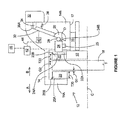
- a vehicle 10 having a brake 12 The brake 12 includes a caliper 14 which is slidably mounted via pin 16 on the vehicle 10, typically on a suspension component of the vehicle 10. Accordingly the caliper 14 can move in the direction of arrow A and in the direction of arrow B.
- the vehicle 10 includes a brake rotor, in this case a brake disc 18 which is rotatably mounted about axis C.
- the brake disc 18 is rotatably connected to a wheel (not shown) which also rotates about axis C.
- Brake pad 20 includes a brake pad back plate 20A and friction material 20B.
- Brake pad 22 includes a brake pad back plate 22A and friction material 22B.
- brake pads 20 and 22 Adjacent brake pad 22 is an adjuster mechanism 24.
- An actuation shaft (or operating shaft) 26 is mounted in the caliper 14 and is rotatable about axis D.
- a roller 28 is supported on the actuation shaft 26 and engages a right hand end (when viewing Figure 1 ) of the adjuster mechanism 24.
- Operating lever 30 is attached to the actuating shaft 26.
- An actuator 32 is mounted on the caliper 14, and includes an actuator rod 34, which engages an end 30A of the actuating lever 30.
- the actuator 32 is a mechanically operated actuator, in this case an air operated actuator.
- the actuator 32 may alternatively be an electrically operated actuator or any non-electrically operated actuator.
- the brakes are in a released condition, operating lever 30 having being rotated clockwise about axis D such that a gap G1 exists between brake pad 20 and brake disc 18 and a gap G2 exists between brake pad 22 and brake disc 18. Accordingly, the released running clearance is G1 + G2.
- the actuator 32 is operated such that the actuator rod extends from the actuator and moves in a direction of arrow A thereby rotating the operating shaft 26 anti-clockwise about axis D. Because the roller 28 is offset from axis D, the roller 28 moves in the direction of arrow A which causes the adjustment mechanism 24 to move in a direction of A which forces the brake pad 22 in the direction of arrow A, thereby closing the gap G2. Continued anti-clockwise rotation of the operating shaft 26 then causes the caliper 14 to move in the direction of arrow B as the hole 17 in the caliper slides on pin 16. This causes gap G1 to close.
- the elasticity in the various brake components allows for the actuator rod to continue to extend from the actuator and continue to move in the direction of arrow A relative to the actuator, in spite of the fact that the brake pads 20 and 22 are in engagement with the brake disc 18.
- the caliper 14 will start to deflect with the side 14a progressively moving further away from side 14b.
- the brake force increases.
- the adjuster mechanism 24 is electrically operated by electric motor 25.
- the adjuster mechanism 24 can be extended (or lengthened) (such that end 24A moves away from end 24B) or retracted (or shortened) (such that end 24A moves towards end 24B) by operation of the electric motor 25. It will be appreciated that by extending the adjuster mechanism 24 the released running clearance will reduce and by retracting (or shortening) the adjuster mechanism 24 the released running clearance will increase.
- the adjuster mechanism 24 is a distinct component from the actuator 32.
- the actuator 32 performs the function of applying and releasing the brake.
- the adjuster mechanism 24 performs the function of adjusting (in particular the running clearance) of the brake.
- the adjuster mechanism is not used to apply the brake.
- the actuator mechanism is not used to adjust the running clearance of the brake.
- the actuator 32 is an air operated actuator though other types of mechanical actuator may be used.
- the adjuster mechanism 24 is electrically operated, i.e. in order to adjust the adjuster mechanism the electric motor 25 must be operated. Adjuster mechanism 24 may take the form of an extendable piston.
- the vehicle 10 includes a sensor 40 and a processor 42, in one embodiment a microprocessor. There is also included a memory 46 such as data storage, such as flash memory.
- the sensor 40 in this case is a position sensor and senses the position of the actuating lever 30.
- the sensor 40 together with the processor 42 and memory 44 can be used to determine the rest position of the actuating lever 30 (as shown in Figure 1 ) and can also be used to determine when the instantaneous running clearance has reduced to zero (but the brakes are not applied).
- the absolute sizes, and any difference in size, of the gaps G1 and G2 can influence the performance of the braking system and so correct calibration of these gaps, either during maintenance or operation, or particularly after replacement of components of the braking system, can be important to the performance of the system in operation.
- the actuator rod 34 will have moved 40 mm in the direction of arrow A.
- the first 20 mm of movement all that occurs is that gap G2 closes and the caliper moves in the direction of arrow B such that gap G1 closes.
- no braking force has yet been applied since the force required to, for example, slide the hole 17 along pin 16 is relatively low and thus the actuator rod 34 moves relatively quickly during its first 20 mm of movement.
- the clamping force progressively increases and therefore the force required to move end 30A through the final 20 mm of movement increases considerably.
- the actuator rod 34 extending more slowly over the second 20 mm of movement than over the first 20 mm of movement.
- the sensor 40 can also determine the rest position of the actuating lever 30. Knowing the rest position of the actuator lever 30 and the position of the actuating lever 30 when the instantaneous running clearance is zero enables the released running clearance to be determined.
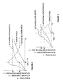
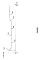
- Fig. 2 there is shown the position of the end 30A of the actuating lever 30 plotted against time as the vehicle operator demands a heavy braking force.
- the actuating lever position is sensed by sensor 40.
- Fig. 2 Also shown on Fig. 2 is the actuating lever speed over the same time period and the brake clamp force over the same time period. The following sets out how analysis of this curve can be used to control clearance between brake pad or shoe and brake disc or drum.
- the actuating lever is positioned as shown in Fig. 1 in the rest condition. This is taken as zero displacement. Because there is an air gap G1, G2, then the brake force is zero. The actuating lever is stationary, and the actuating lever speed is zero.
- the vehicle operator applies the brakes which causes the actuator 32 to move the actuator rod 34 in the direction of arrow A.
- the characteristics of the brake are such that the end 30A of the actuating lever moves as shown on Figure 2 . Since the actuating lever position with respect to time is known, then it is possible to determine the actuating lever speed with respect to time. This has been plotted on Fig. 2 .
- the actuating lever speed has reached a maximum, following which the speed decreases. This maximum speed coincides with the moment when the instantaneous running clearance has reduced to zero.
- a clamping force begins to be generated which tends to slow down the speed of actuating lever.
- the actuator rod 34 has extended 40 mm and the actuating lever speed is relatively slower when compared with the peak at time T 1 .
- the brake force is relatively high.
- FIG. 3 With reference to Figure 3 there is shown a plot of actuating lever speed, actuating lever position, and brake force with respect to time wherein the vehicle operator has applied the brake relatively slowly and relatively lightly. Under these circumstances it has taken time T 3 for the instantaneous running clearance to close to zero. It will be appreciated that the brake has been applied relatively lightly since the maximum displacement of the actuator rod 34 is only 30 mm at time T 4 . Nevertheless, it will be appreciated that Figure 3 shows similar characteristics, namely that at the point of maximum lever speed, the instantaneous running clearance has reduced to zero. After this time a clamp force starts to be generated.
- a new brake when it has been designed, it may be fitted to a test vehicle and fitted with various instrumentation including, for example, a position sensor monitoring the position of a particular component of the brake assembly, and also a force sensor to measure the clamping force for the caliper.
- the test vehicle will then be driven and braked under various circumstances. Analysis of the data may show that at or near the zero instantaneous running clearance position of the brake component (as determined by the force sensor), the measured parameter may have a particular characteristic.
- the measured parameter was velocity and the characteristic of the velocity that the point when the brake reached a zero instantaneous running clearance was a peak in the velocity.
- a peak in the velocity profile of component 30 is a characteristic of the parameter (velocity) which is known (as a result of testing) to be indicative of a zero instantaneous running clearance position of the brake.
- Subsequent vehicles such as production vehicles fitted with a similar brake and with sensor 40, but without any force sensor can determine the zero instantaneous running clearance position of the brake by determining the position of the brake when the parameter (velocity of component 30) has a characteristic (a velocity peak) that is indicative of a zero instantaneous running clearance. This can be carried out by comparing the monitored (or measured) velocity peak with the predetermined characteristic (as measured on the test vehicle).
- the system can determine that the measured velocity peak is indeed indicative of a zero instantaneous running clearance position of the brake.
- a velocity peak may be produced which is not indicative of zero instantaneous running clearance position of the brake.
- the velocity peak can be compared with the predetermined velocity peaks and where they are not sufficiently similar the system can determine that the measured velocity peak was not indicative of a zero instantaneous running clearance position of the brake and therefore ignore this particular velocity peak for the purposes of running clearance adjustment.
- the adjustment mechanism can be adjusted (either by being lengthened or shortened) in order to adjust the actual released running clearance to the desired released running clearance.
- the adjustment mechanism can be adjusted by being lengthened to compensate for the wear.
- the adjustment mechanism can be adjusted by being shortened in order to increase the actual running clearance to nearer the desired running clearance.
- the adjustment mechanism can again be adjusted by being lengthened to compensate for the now cool brake.
- a peak velocity of end 30A coincides with a zero instantaneous running clearance condition.
- a zero instantaneous running clearance condition can also be determined during brake release.
- the only forces acting on the actuating lever 30 are relatively light return spring forces designed into the brake to return the actuating lever 30 to the position shown in Figure 1 .
- Tension spring 36 is a diagrammatical representation of a return spring.
- Figure 4 shows a plot of the actuating lever speed of brake 12 plotted against time during an application and release of the brake.
- the sequence of events that occurs is as follows:-
- the peak in the graph at time T 6 is an indication that the brake is near a zero instantaneous running clearance position.
- the trough in the graph at time T 9 is an indication that the brake is near a zero instantaneous running clearance position during release.
- an electrically operated clearance control system is able to perform two functions, firstly it is able to maintain a desired running clearance between the rotor and a friction surface of the brake pad or brake shoe. Secondly, it is able to act as a wear indicator. As such, the requirement for a separate wear indicator is no longer required and accordingly the cost and space requirement of such a separate mechanical or electro-mechanical wear indicator are no longer incurred.
- the processor can determine if any usable life remains in a brake component without the need for any electrically (or mechanically) operated clearance control system.
- the system described is also capable of determining if any usable fatigue life remains in a brake component.
- actuating lever 30 It is assumed, for example, that actuating lever 30 has a fatigue limit. Throughout the life of the vehicle 10 the brake 12 will be applied typically many hundreds of thousands of times. Each application and release of the brake constitutes one fatigue cycle and in particular for the present example one fatigue cycle of actuating lever 30.
- the processor 43 in conjunction with memory 46 may "count" the number of fatigue cycles.
- the processor could count the number of times the brake is applied, this being a good indication of a fatigue cycle, i.e. an application and release of the brake.
- a released running clearance can be described as the sum of the gap between each pad and its associated surface of the brake disc.
- a gap can appear between brake pad 20 and that part of caliper 14 which the brake pad engages when the brake is on.
- a gap can appear between brake pad 22 and that part of the adjuster mechanism 24 which the pad engages when the brake is on.
- the released running clearance is the sum of gaps G1, G2, any gap existing between pad 20 and caliper 14 and any gap existing between pad 22 and adjuster mechanism 24.
- the sensor 40 is a linear sensor. Any type of position sensor could be used including rotary sensors. As shown in Figure 1 , the position of the actuating lever 30 is sensed by sensor 40 and in other embodiments any other component of the brake could be sensed. As mentioned above, sensor 40 is a position sensor and in other embodiments velocity sensors or accelerometers could be used to sense the velocity or acceleration of any brake component. This is possible, since knowing the change of displacement over time allows calculation of velocity and acceleration and similarly knowing the change in speed over time allows calculation of position and acceleration, and similarly knowing change of acceleration over time allows calculation of position and speed. This can be applied to monitoring for a running clearance of the brake, monitoring for a number of fatigue cycles, or for determining whether a braking component has been properly released for replacement or not.
- Different embodiments of brakes will have different characteristics, for example the elasticity of components of one embodiment may be different to the elasticity of equivalent components of a second embodiment.
- a desired released running clearance of one embodiment may be different to a desired released running clearance of another embodiment.
- a particular embodiment of a brake may be tested to determine the operating characteristics both during application of the brake and during release of the brake. Testing may be carried out at different application rates and different release rates. Testing may be carried out with different release running clearances. Testing may be carried out at different brake temperatures. Testing may be carried out when the brake is new and also when the brake is old. Once testing has been completed for a particular embodiment, the operating characteristics will be known. It will then be possible to programme processor 42 with certain characteristics (or functions) relating to the tested brake.
- sensor 40 When the brake is applied sensor 40 sends a signal (via line 44) to processor 42, this signal will be compared with the predetermined function to determine the actual released running clearance.
- Processor 42 can compare the actual released running clearance with the desired released running clearance. Any difference between the actual released running clearance and the desired released running clearance can then be corrected by processor 42 commanding the adjustment of adjuster mechanism 24.
- each particular embodiment (design) of a brake will have its own particular operating characteristic and in particular its own desired released running clearance
- the processor associated with that particular design of brake will be programmed with the characteristics (function) of that design. It is therefore important that a braking system as a whole has components which comply with the specifications originally programmed into the system by the manufacturer. This is of particular importance where the braking actions and conditions are monitored to adjust braking performance and running clearance and to estimate the remaining life of components.
- a braking system including an actuator, in adjustment mechanism 24, which can be actuated to control a running clearance between a friction element, such as a pad or shoe, of a brake or braking assembly, and a corresponding friction surface, such as a rotor, disc or drum of the braking assembly.
- a friction element such as a pad or shoe
- a corresponding friction surface such as a rotor, disc or drum
- the system illustrated in the preceding figures can also be adapted to improve efficiencies in the maintenance procedures of a braking system.
- the adjustment of the running clearance in a braking system particularly those which are mechanically actuated, the pad replacement process requires a technician to mechanically and manually wind back a mechanical adjustment mechanism to allow sufficient clearance for the brake pad to be removed from a caliper.
- After replacement of the friction element such as a brake pad, either with the same or a new brake pad it is also a manual process that is required to set a desired running clearance.
- These processes can be both time consuming, require significant manual labour, which is an additional cost in the maintenance procedure, and is also subject to human error, since the manual adjustment is often carried out by eye by the technician. Accuracy of the adjustment therefore depends on the training and experience and attention to detail of the technician in question. In such critical systems as braking systems, this can introduce undesirable risk to the correct functioning of the braking system.
- the invention therefore describes a system and a related method for automatically adjusting the running clearance using a controller.
- the method of the invention may be carried out in a controller integral to the braking system, or integral to a vehicle or machinery into which the braking system is integrated. It may also be carried out in a separate controller or diagnostic device, which is temporarily connected to the system for temporary reasons, such maintenance or repair.
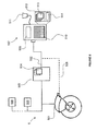
- An example of such a device, connected into a system of the invention, is illustrated in Figure 5 .
- the system 5 includes a brake 501, which may be connected to a CAN bus 502 of the system 5 via data connection to the CAN bus 502, although it is not essential that the brake be connected electronically to the CAN bus, the brake and CAN bus may simply be separate parts of the same machinery or vehicle.
- the CAN bus 502 is connected to a controller 503, which may contain a database 504 carrying data relating to various parameters of the system and of the vehicle or machinery to which it is installed.
- the CAN bus may include further connections to other parts of the vehicle or machinery, such as engine management systems 505, and safety systems 506.
- the brake can also be connected to other control systems such as electrical, hydraulic or pneumatic control and power input systems.
- the method of the present invention can therefore comprise monitoring signals in the form of data on the CAN bus, or in the form of electrical currents and hydraulic or pneumatic flows or pressures supplied to elements of the brake, such as the adjuster mechanism 24, directly.
- An electronic diagnostic tool which may be a specifically created electronic device 507, or a programmable computer carrying appropriate software and connections, can be connected to the CAN bus controller 503 directly, or via CAN bus 502..
- the diagnostic tool 507 can query the CAN bus to obtain data representing signals relating to operation of the brake 501. These data can be used in the present invention as the monitored signals for adjusting the running clearance if desired.
- the diagnostic tool 507 may alternatively or additionally be connected directly to the brake 501 by a connection indicated by line 508. In this case the diagnostic tool can provide direct control signals and/or power to the brake to actuate the first and second actuators in accordance with the methods of the invention described herein.
- the diagnostic tool 507 may include a screen 509 for displaying information to a user, a keypad 510 for manual data input and a scanning device 511 for reading codes from replacement parts, or from the vehicle or machinery on which the brake is installed.
- the codes identifying the vehicle, machinery or replacement parts can enable the controller to determine the necessary thresholds and distances for retracting the actuator, to provide sufficient distance for removing the friction element, or to set the required running distance for operation.
- the device 507 may include a memory 512.
- the memory 512 may include a computer program product 514 of the invention, for execution by a controller or processor in the device 507, to carry out the methods of the invention described herein, as will be apparent in reading the following description of the methods of the invention.
- a typical known brake pad replacement process is illustrated in Figure 6 .
- the key steps are illustrated in the figure, but additional steps may also be present.
- a technician may be necessary for a technician to release the parking brake and/or to set a control system into a maintenance mode. This may involve a sequence of steps, such as setting the ignition key to a certain position, operating a further input, such as a brake actuator, and setting the key to a second position to activate the maintenance function. Mud guards may need to be removed and brake components vacuumed to remove brake dust.
- step 601 wheels are removed to allow access to the brake by the technician.
- step 602 the technician manually adjusts a running clearance to allow the friction element to be removed from the braking system, such as from a caliper of a disc braking system. This may be typically carried out by turning an adjustment screw.
- step 603 further friction element retainers, which mechanically retain the friction element in place, may be removed.
- step 604 the friction element is removed from the braking system.
- step 605 the correct movement of a brake caliper may be checked to ensure that the system is free to move the friction elements appropriately and is therefore suitable for further service.
- a new replacement friction element is placed in the braking system, preferably being a pad inserted into a caliper, in the case of a disc and caliper based braking system.
- step 607 friction element retainers are replaced to mechanically retain the friction element in place in the caliper.
- step 608 the technician manually adjusts the running clearance down to zero. This can be achieved by tightening an adjustment screw as far as is possible until resistance is met, indicating the running clearance has reached zero and, e.g. the pad is in contact with the disc.
- step 609 the technician manually de-adjusts the clearance to provide the desired running clearance.
- step 610 the technician checks that the rotors, such as discs or hubs of the brake system are free to rotate, having sufficient a running clearance.
- step 611 the wheels are replaced and any guards or other parts removed to enable the maintenance are put back in place. If on a vehicle, then a parking brake may be reapplied at this point.
- steps 602 and 608 to 610 Key parts of the described process which involve significant manual input are steps 602 and 608 to 610.
- the automated running clearance setting method enabled by the invention as described in the following can remove those steps and so reduce the time and amount of manual labour required for the maintenance process.
- an initial peak 701 is seen when the motor first starts to move. After this peak, the motor current drops to a substantially steady state indicated by substantially straight portion 702.
- a second, minor peak 703 may be seen when the adjustor first contacts the pad. This will often be the case when a pad has been newly installed in the system.
- the current then continues at a substantially steady state during section 704, once the friction element is advanced towards the corresponding friction surface. This latter current level 704 may be substantially the same or slightly higher than the initial current during period 702.
- a further rise in the current 705 will be seen when the friction element contacts the corresponding friction surface (i.e. the brake pad contacting the rotor or disc in the example of a disc and caliper based braking system) until a peak steady state current level 706 is reached. This occurs as the motor is prevented from moving by the contact of the friction element with the corresponding friction surface when the running clearance is reduced to zero.
- the current drawn by the motor used to adjust the running clearance can therefore provide a signal indicative of a load on the motor.
- a hydraulic or pneumatic pressure may be indicative of a load on the actuator.
- strain gauges could be used in a mechanical system to provide a signal indicative of a load on an adjuster mechanism for adjusting a running clearance of a braking system.
- Such a signal indicative of a load on an actuator can then be monitored and a series of logic steps applied to the signal value can be used to determine when the running clearance has been reduced to zero.
- a series of logic steps applied to the signal value can be used to determine when the running clearance has been reduced to zero.
- a high steady state motor current 706 will be detected.
- the actuator can immediately be retracted by a predetermined amount to set a running clearance. This may be a running clearance sufficient to enable normal operation of the system, or a release running clearance, which is sufficient to release the brake pad to be removed from the system. Once retracted, a value relating to the motor position can be set to zero once the friction element is withdrawn away from the friction surface. In the alternative, if the pad is determined to be moving freely and not pressing against the corresponding friction surface, then a pad-replacement clearance-setting function can be initiated.
- the pad replacement clearance-setting function can be used to set either:
- the above process checks for an initial high actuator load, established at 701 when the actuator starts moving, based on detection of the actuator load being higher than a first threshold, the actuator position being advanced relative to its initial position (i.e. moving), and the actuator load, after a set time threshold, being less than the initial threshold and greater than zero, or alternatively greater than a predetermined lower threshold.
- the actuator load value and the actuator position value are both checked, then the actuator position is reset once the running clearance is zero, in accordance with the following logic:
- the above process determines when the running clearance has reached zero after the initial peak and then sets the base actuator position to zero. This value can then be used as a reference to determine wear of the pad during its life in the system.
- the amount by which the actuator is retracted in step 2c) is set as the chosen operational target running clearance, i.e. the running clearance during normal use which can be set to a chosen design value for systems, according to the best performance parameters of the system.
- a first carrying out of the installation and calibration methods for setting the required clearance allow one series of steps to be carried out to determine where the zero running clearance point is, and then a second series of steps to be carried out for retracting the actuator by a sufficient amount for the friction element or elements to be removed from the braking system.
- the retraction may also be by a sufficient distance to allow a new replacement friction element to be installed in the system.
- a second carrying out of the method can then allow the brakes to be applied, in effect, by running the running clearance down to zero, and then the running clearance can be set, by retraction of the actuator, at a chosen gap as required for the braking system in question.
- the advantages of using this system can include eliminating the risk of incorrect running clearance being manually set after friction elements have been replaced and the overall time taken to carry out friction element removal and replacement is reduced, which can result in labour and related cost and time savings. Further, the carrying out of the process in an automated way in a controller can be more repeatable and more reliable, improving overall safety of vehicles which are maintained according to the methods described herein.
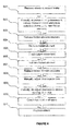
- Figure 8 shows a revised maintenance process, which includes less operator steps than that shown in Figure 6 , due to the implementation of the running clearance adjustment methods described herein.
- Step 801 involves the same process as step 601, and the same preliminary steps described in relation to Figure 6 may also be carried out.
- Step 802 includes causing a controller to adjust the running clearance to release a friction element from the braking system, and may include any or all of the steps described above and the logic applied in relation to the above description of Figure 6 .
- This automated process can be carried out quickly and without the need for additional tools, so can speed up the overall process and reduce the burden on a technician carrying out maintenance.
- Steps 803 to 807 are essentially the same as steps 603 to 607 described in relation to Figure 6 .
- Step 808 allows steps 608 to 610 of Figure 6 to be replaced by the automated running clearance adjustment process described herein. This again reduces the need for tools and can be carried out rapidly and repeatably, reducing the burden on technicians and improving reliability of the process.
- the final step 809 is the same as the final step described in relation to Figure 6 .
- the setting of the running clearance to a target operational value according to the methods described herein may be initiated automatically once a technician or driver switches on the ignition of machinery or a vehicle to which the braking system is applied. Such a calibration or setting of running clearance could also be carried out each time the ignition or a control system of vehicle or machinery is switched on, to ensure that the braking systems are correctly calibrated with an appropriate running clearance before every use of the vehicle or machinery. This would again improve overall safety of the vehicle or machinery.
- the methods may be carried out in a controller of the vehicle or machinery to which the braking system is applied, or may alternatively be carried out in a separate diagnostic device, which may be an electronic controller, computer or programmable device.
Priority Applications (2)
| Application Number | Priority Date | Filing Date | Title |
|---|---|---|---|
| EP14185036.2A EP2998607A1 (de) | 2014-09-16 | 2014-09-16 | Verfahren und System zur Einstellung des Laufspiels einer Bremskomponente |
| US14/848,939 US20160076609A1 (en) | 2014-09-16 | 2015-09-09 | Method and system for setting a braking component running clearance |
Applications Claiming Priority (1)
| Application Number | Priority Date | Filing Date | Title |
|---|---|---|---|
| EP14185036.2A EP2998607A1 (de) | 2014-09-16 | 2014-09-16 | Verfahren und System zur Einstellung des Laufspiels einer Bremskomponente |
Publications (1)
| Publication Number | Publication Date |
|---|---|
| EP2998607A1 true EP2998607A1 (de) | 2016-03-23 |
Family
ID=51570297
Family Applications (1)
| Application Number | Title | Priority Date | Filing Date |
|---|---|---|---|
| EP14185036.2A Withdrawn EP2998607A1 (de) | 2014-09-16 | 2014-09-16 | Verfahren und System zur Einstellung des Laufspiels einer Bremskomponente |
Country Status (2)
| Country | Link |
|---|---|
| US (1) | US20160076609A1 (de) |
| EP (1) | EP2998607A1 (de) |
Cited By (2)
| Publication number | Priority date | Publication date | Assignee | Title |
|---|---|---|---|---|
| EP3251908A1 (de) * | 2016-06-03 | 2017-12-06 | Meritor Heavy Vehicle Braking Systems (UK) Limited | Bremssystem und verfahren zur steuerung mit luftspaltschätzung |
| EP4306373A1 (de) * | 2022-07-13 | 2024-01-17 | Meritor Heavy Vehicle Braking Systems (UK) Limited | Verfahren und vorrichtung zum berechnen des laufspiels einer scheibenbremse |
Families Citing this family (14)
| Publication number | Priority date | Publication date | Assignee | Title |
|---|---|---|---|---|
| EP2837533B1 (de) * | 2013-08-15 | 2019-04-24 | Meritor Heavy Vehicle Braking Systems (UK) Limited | Verfahren zum Einstellen einer Bremse |
| US10570974B2 (en) | 2015-04-17 | 2020-02-25 | Goodrich Corporation | Brake position and wear detection systems and methods |
| DE102016214219A1 (de) * | 2016-08-02 | 2018-02-08 | Robert Bosch Gmbh | Verfahren zur Wartung eines Bremssystems mit hydraulischer Fahrzeugbremse und elektromechanischer Bremsvorrichtung |
| JP6787093B2 (ja) * | 2016-12-06 | 2020-11-18 | 日本製鉄株式会社 | ディスクブレーキ装置とディスクブレーキ監視方法 |
| US20190011001A1 (en) * | 2017-07-06 | 2019-01-10 | Amber Kinetics, Inc. | Emergency Braking of a Flywheel |
| US10800386B2 (en) | 2017-07-24 | 2020-10-13 | Goodrich Corporation | Brake position system |
| US10493962B2 (en) * | 2017-07-24 | 2019-12-03 | Goodrich Corporation | Brake position system |
| HUE058761T2 (hu) * | 2018-09-18 | 2022-09-28 | Knorr Bremse Systeme Fuer Nutzfahrzeuge Gmbh | Fékberendezés hézagának beállítására szolgáló eljárás és fékberendezés |
| JP7262992B2 (ja) * | 2018-12-17 | 2023-04-24 | ナブテスコ株式会社 | 摩耗量算出装置、異常摩耗判定装置、及びブレーキ装置 |
| DE102019100481A1 (de) * | 2019-01-10 | 2020-07-16 | Wabco Europe Bvba | Verfahren zum Einstellen eines Lüftspiels einer elektromechanischen Bremse sowie betreffende Bremse und Steuergerät |
| CN110410440B (zh) * | 2019-07-31 | 2020-12-15 | 青岛方冠摩擦材料有限公司 | 汽车刹车片磨损检测装置 |
| CN112097717B (zh) * | 2020-07-27 | 2022-07-12 | 兰州交通大学 | 一种基于碰撞振动的间隙检测系统及方法 |
| IT202000021220A1 (it) * | 2020-09-08 | 2022-03-08 | Alessio VARDIERO | Sistema di frenatura e metodo |
| US11577711B2 (en) * | 2021-03-04 | 2023-02-14 | Akebono Brake Industry Co., Ltd. | Method of controlling a brake for service operation |
Citations (5)
| Publication number | Priority date | Publication date | Assignee | Title |
|---|---|---|---|---|
| FR2757918A1 (fr) * | 1996-12-30 | 1998-07-03 | Bosch Gmbh Robert | Dispositif de freinage a moteur electrique |
| EP0995923A2 (de) * | 1998-10-24 | 2000-04-26 | Meritor Automotive, Inc. | Fahrzeugbremse mit elektromotorischer Regelung des Luftspiels |
| EP1524449A1 (de) * | 2003-10-16 | 2005-04-20 | Meritor Heavy Vehicle Braking Systems (UK) Limited | System und Verfahren zur Steuerung des Lüftspiels bei Scheibenbremsen. |
| DE102010063353A1 (de) * | 2010-12-17 | 2012-06-21 | Robert Bosch Gmbh | Verfahren zum Einstellen der von einer Feststellbremse ausgeübten Klemmkraft |
| EP2650556A1 (de) | 2012-03-28 | 2013-10-16 | Meritor Heavy Vehicle Braking Systems (UK) Limited | Bremse |
Family Cites Families (11)
| Publication number | Priority date | Publication date | Assignee | Title |
|---|---|---|---|---|
| US6969126B2 (en) * | 2000-02-28 | 2005-11-29 | Hitachi, Ltd. | Braking apparatus and method of controlling the same |
| DE10325092B4 (de) * | 2003-06-03 | 2006-05-11 | Federal-Mogul Friction Products Gmbh | Bremsbelag-Verschleißanzeigegerät |
| WO2007091337A1 (ja) * | 2006-02-08 | 2007-08-16 | Hitachi, Ltd. | 電動ブレーキ装置 |
| JP2010500511A (ja) * | 2006-08-07 | 2010-01-07 | コンティネンタル・テーベス・アクチエンゲゼルシヤフト・ウント・コンパニー・オッフェネ・ハンデルスゲゼルシヤフト | 電気機械式パーキングブレーキ及びその動作方法 |
| DE102008011288B4 (de) * | 2008-02-27 | 2013-08-14 | Knorr-Bremse Systeme für Schienenfahrzeuge GmbH | Vorrichtung zur Überwachung der Belagdicke eines Bremsbelags einer Reibungsbremse eines Fahrzeugs |
| US7877216B2 (en) * | 2008-07-30 | 2011-01-25 | Honeywell International Inc. | Method, system, and apparatus for friction pad wear and brake condition monitoring |
| DE102010063365B4 (de) * | 2010-12-17 | 2023-01-19 | Robert Bosch Gmbh | Verfahren zum Einstellen der von einer Feststellbremse ausgeübten Klemmkraft |
| DE102011004205A1 (de) * | 2011-02-16 | 2012-08-16 | Robert Bosch Gmbh | System und Verfahren zum Identifizieren, Diagnostizieren, Warten und Reparieren eines Fahrzeugs |
| GB201220882D0 (en) * | 2012-11-20 | 2013-01-02 | Trw Ltd | An electronic park brake release tool |
| US20140279397A1 (en) * | 2013-03-14 | 2014-09-18 | David Warren Schmidt | Retrieving Vehicular Collateral via Wi-Fi |
| EP2955408B1 (de) * | 2014-06-13 | 2019-11-20 | Meritor Heavy Vehicle Braking Systems (UK) Limited | Bremskomponentenaustauschsystem und -verfahren |
-
2014
- 2014-09-16 EP EP14185036.2A patent/EP2998607A1/de not_active Withdrawn
-
2015
- 2015-09-09 US US14/848,939 patent/US20160076609A1/en not_active Abandoned
Patent Citations (5)
| Publication number | Priority date | Publication date | Assignee | Title |
|---|---|---|---|---|
| FR2757918A1 (fr) * | 1996-12-30 | 1998-07-03 | Bosch Gmbh Robert | Dispositif de freinage a moteur electrique |
| EP0995923A2 (de) * | 1998-10-24 | 2000-04-26 | Meritor Automotive, Inc. | Fahrzeugbremse mit elektromotorischer Regelung des Luftspiels |
| EP1524449A1 (de) * | 2003-10-16 | 2005-04-20 | Meritor Heavy Vehicle Braking Systems (UK) Limited | System und Verfahren zur Steuerung des Lüftspiels bei Scheibenbremsen. |
| DE102010063353A1 (de) * | 2010-12-17 | 2012-06-21 | Robert Bosch Gmbh | Verfahren zum Einstellen der von einer Feststellbremse ausgeübten Klemmkraft |
| EP2650556A1 (de) | 2012-03-28 | 2013-10-16 | Meritor Heavy Vehicle Braking Systems (UK) Limited | Bremse |
Cited By (3)
| Publication number | Priority date | Publication date | Assignee | Title |
|---|---|---|---|---|
| EP3251908A1 (de) * | 2016-06-03 | 2017-12-06 | Meritor Heavy Vehicle Braking Systems (UK) Limited | Bremssystem und verfahren zur steuerung mit luftspaltschätzung |
| US10422396B2 (en) | 2016-06-03 | 2019-09-24 | Meritor Heavy Vehicle Braking Systems (Uk) Limited | Brake system and method of control with air gap estimation |
| EP4306373A1 (de) * | 2022-07-13 | 2024-01-17 | Meritor Heavy Vehicle Braking Systems (UK) Limited | Verfahren und vorrichtung zum berechnen des laufspiels einer scheibenbremse |
Also Published As
| Publication number | Publication date |
|---|---|
| US20160076609A1 (en) | 2016-03-17 |
Similar Documents
| Publication | Publication Date | Title |
|---|---|---|
| EP2998607A1 (de) | Verfahren und System zur Einstellung des Laufspiels einer Bremskomponente | |
| EP2955408B1 (de) | Bremskomponentenaustauschsystem und -verfahren | |
| EP2650556B1 (de) | Bremse | |
| CN108430844B (zh) | 用于使用准弹性释放末端停止件以可靠方式释放电致动器的方法和装置 | |
| JP5535924B2 (ja) | パーキングブレーキおよびそれを動作するための方法 | |
| KR102096148B1 (ko) | 자동차 전기식 주차 브레이크 시스템을 위한 주차 브레이크 작동 방법 | |
| CN106167007B (zh) | 用于机动车的制动装置和用于对所述制动装置的损坏进行探测的方法 | |
| KR101836628B1 (ko) | 전동식 브레이크 장치 및 그 제어 방법 | |
| EP2993096B1 (de) | System und verfahren zur einstellung eines nullkraftwerts | |
| US20090164172A1 (en) | Method and processing unit for determining a performance parameter of a brake | |
| KR101890447B1 (ko) | 주차 브레이크에 의해 가해지는 고정력을 조정하기 위한 방법 | |
| CN110199136B (zh) | 制动器衬片磨损传感器 | |
| JP7449854B2 (ja) | 車両の電気駐車ブレーキシステムによりパッドとブレーキディスクとの間に付与可能な制動力を推定する方法、及びこのような方法を実施する車両の電気駐車ブレーキシステム | |
| CN210594785U (zh) | 制动装置及电梯 | |
| CA3010281C (en) | Moving type tail stock | |
| CN112771458A (zh) | 用于机电接合系统的状态分析的方法和执行该方法的机电接合系统 | |
| US20220227346A1 (en) | Electromechanical actuator for a vehicle brake with increased service life | |
| KR102179748B1 (ko) | 브레이크 패드 상태 모니터링 장치 및 방법 | |
| EP2644466A1 (de) | Verfahren zur Abschätzung der übrigen Lebensdauer eines Bresmteils | |
| KR101928527B1 (ko) | 전류 제어를 이용한 전자 기계식 제동 시스템 및 그의 초기화 방법 | |
| JP7478759B2 (ja) | 増加した耐用年数を伴う車両ブレーキ用電気機械式アクチュエータ | |
| EP2644929A1 (de) | Verfahren zum Bestimmen des Anlegepunkts einer Bremse | |
| US20230145033A1 (en) | Electronic parking brake system and control method thereof | |
| CN117404409A (zh) | 用于计算盘式制动器的运行间隙的方法和设备 | |
| GB2500777A (en) | Monitoring of an electromechnical parking brake |
Legal Events
| Date | Code | Title | Description |
|---|---|---|---|
| PUAI | Public reference made under article 153(3) epc to a published international application that has entered the european phase |
Free format text: ORIGINAL CODE: 0009012 |
|
| AK | Designated contracting states |
Kind code of ref document: A1 Designated state(s): AL AT BE BG CH CY CZ DE DK EE ES FI FR GB GR HR HU IE IS IT LI LT LU LV MC MK MT NL NO PL PT RO RS SE SI SK SM TR |
|
| AX | Request for extension of the european patent |
Extension state: BA ME |
|
| 17P | Request for examination filed |
Effective date: 20160906 |
|
| RBV | Designated contracting states (corrected) |
Designated state(s): AL AT BE BG CH CY CZ DE DK EE ES FI FR GB GR HR HU IE IS IT LI LT LU LV MC MK MT NL NO PL PT RO RS SE SI SK SM TR |
|
| 17Q | First examination report despatched |
Effective date: 20190402 |
|
| STAA | Information on the status of an ep patent application or granted ep patent |
Free format text: STATUS: THE APPLICATION HAS BEEN WITHDRAWN |
|
| 18W | Application withdrawn |
Effective date: 20190501 |