EP3251908B1 - Bremssystem und verfahren zur steuerung mit luftspaltschätzung - Google Patents
Bremssystem und verfahren zur steuerung mit luftspaltschätzung Download PDFInfo
- Publication number
- EP3251908B1 EP3251908B1 EP16172941.3A EP16172941A EP3251908B1 EP 3251908 B1 EP3251908 B1 EP 3251908B1 EP 16172941 A EP16172941 A EP 16172941A EP 3251908 B1 EP3251908 B1 EP 3251908B1
- Authority
- EP
- European Patent Office
- Prior art keywords
- brake
- air gap
- pad assembly
- signal
- brake pad
- Prior art date
- Legal status (The legal status is an assumption and is not a legal conclusion. Google has not performed a legal analysis and makes no representation as to the accuracy of the status listed.)
- Active
Links
Images


Classifications
-
- F—MECHANICAL ENGINEERING; LIGHTING; HEATING; WEAPONS; BLASTING
- F16—ENGINEERING ELEMENTS AND UNITS; GENERAL MEASURES FOR PRODUCING AND MAINTAINING EFFECTIVE FUNCTIONING OF MACHINES OR INSTALLATIONS; THERMAL INSULATION IN GENERAL
- F16D—COUPLINGS FOR TRANSMITTING ROTATION; CLUTCHES; BRAKES
- F16D65/00—Parts or details
- F16D65/38—Slack adjusters
- F16D65/40—Slack adjusters mechanical
- F16D65/62—Slack adjusters mechanical self-acting in both directions for adjusting excessive and insufficient play
- F16D65/66—Slack adjusters mechanical self-acting in both directions for adjusting excessive and insufficient play with screw-thread and nut
-
- B—PERFORMING OPERATIONS; TRANSPORTING
- B60—VEHICLES IN GENERAL
- B60T—VEHICLE BRAKE CONTROL SYSTEMS OR PARTS THEREOF; BRAKE CONTROL SYSTEMS OR PARTS THEREOF, IN GENERAL; ARRANGEMENT OF BRAKING ELEMENTS ON VEHICLES IN GENERAL; PORTABLE DEVICES FOR PREVENTING UNWANTED MOVEMENT OF VEHICLES; VEHICLE MODIFICATIONS TO FACILITATE COOLING OF BRAKES
- B60T17/00—Component parts, details, or accessories of power brake systems not covered by groups B60T8/00, B60T13/00 or B60T15/00, or presenting other characteristic features
- B60T17/18—Safety devices; Monitoring
- B60T17/22—Devices for monitoring or checking brake systems; Signal devices
-
- B—PERFORMING OPERATIONS; TRANSPORTING
- B60—VEHICLES IN GENERAL
- B60T—VEHICLE BRAKE CONTROL SYSTEMS OR PARTS THEREOF; BRAKE CONTROL SYSTEMS OR PARTS THEREOF, IN GENERAL; ARRANGEMENT OF BRAKING ELEMENTS ON VEHICLES IN GENERAL; PORTABLE DEVICES FOR PREVENTING UNWANTED MOVEMENT OF VEHICLES; VEHICLE MODIFICATIONS TO FACILITATE COOLING OF BRAKES
- B60T1/00—Arrangements of braking elements, i.e. of those parts where braking effect occurs specially for vehicles
- B60T1/02—Arrangements of braking elements, i.e. of those parts where braking effect occurs specially for vehicles acting by retarding wheels
- B60T1/06—Arrangements of braking elements, i.e. of those parts where braking effect occurs specially for vehicles acting by retarding wheels acting otherwise than on tread, e.g. employing rim, drum, disc, or transmission or on double wheels
- B60T1/065—Arrangements of braking elements, i.e. of those parts where braking effect occurs specially for vehicles acting by retarding wheels acting otherwise than on tread, e.g. employing rim, drum, disc, or transmission or on double wheels employing disc
-
- B—PERFORMING OPERATIONS; TRANSPORTING
- B60—VEHICLES IN GENERAL
- B60T—VEHICLE BRAKE CONTROL SYSTEMS OR PARTS THEREOF; BRAKE CONTROL SYSTEMS OR PARTS THEREOF, IN GENERAL; ARRANGEMENT OF BRAKING ELEMENTS ON VEHICLES IN GENERAL; PORTABLE DEVICES FOR PREVENTING UNWANTED MOVEMENT OF VEHICLES; VEHICLE MODIFICATIONS TO FACILITATE COOLING OF BRAKES
- B60T13/00—Transmitting braking action from initiating means to ultimate brake actuator with power assistance or drive; Brake systems incorporating such transmitting means, e.g. air-pressure brake systems
- B60T13/74—Transmitting braking action from initiating means to ultimate brake actuator with power assistance or drive; Brake systems incorporating such transmitting means, e.g. air-pressure brake systems with electrical assistance or drive
- B60T13/741—Transmitting braking action from initiating means to ultimate brake actuator with power assistance or drive; Brake systems incorporating such transmitting means, e.g. air-pressure brake systems with electrical assistance or drive acting on an ultimate actuator
-
- F—MECHANICAL ENGINEERING; LIGHTING; HEATING; WEAPONS; BLASTING
- F16—ENGINEERING ELEMENTS AND UNITS; GENERAL MEASURES FOR PRODUCING AND MAINTAINING EFFECTIVE FUNCTIONING OF MACHINES OR INSTALLATIONS; THERMAL INSULATION IN GENERAL
- F16D—COUPLINGS FOR TRANSMITTING ROTATION; CLUTCHES; BRAKES
- F16D66/00—Arrangements for monitoring working conditions, e.g. wear, temperature
- F16D66/02—Apparatus for indicating wear
- F16D66/021—Apparatus for indicating wear using electrical detection or indication means
-
- F—MECHANICAL ENGINEERING; LIGHTING; HEATING; WEAPONS; BLASTING
- F16—ENGINEERING ELEMENTS AND UNITS; GENERAL MEASURES FOR PRODUCING AND MAINTAINING EFFECTIVE FUNCTIONING OF MACHINES OR INSTALLATIONS; THERMAL INSULATION IN GENERAL
- F16D—COUPLINGS FOR TRANSMITTING ROTATION; CLUTCHES; BRAKES
- F16D65/00—Parts or details
- F16D65/38—Slack adjusters
- F16D2065/386—Slack adjusters driven electrically
-
- F—MECHANICAL ENGINEERING; LIGHTING; HEATING; WEAPONS; BLASTING
- F16—ENGINEERING ELEMENTS AND UNITS; GENERAL MEASURES FOR PRODUCING AND MAINTAINING EFFECTIVE FUNCTIONING OF MACHINES OR INSTALLATIONS; THERMAL INSULATION IN GENERAL
- F16D—COUPLINGS FOR TRANSMITTING ROTATION; CLUTCHES; BRAKES
- F16D66/00—Arrangements for monitoring working conditions, e.g. wear, temperature
- F16D2066/003—Position, angle or speed
Definitions
- This patent application relates to a brake system and method of control in which an air gap between a brake friction member and a brake pad assembly may be estimated.
- the present invention provides an improved air gap detector system.
- a method of controlling a brake system comprising:
- a method of controlling a brake system comprising:
- a brake system comprising:
- the brake system 10 may be provided with a vehicle, such as a motor vehicle like a truck, farm equipment, or military transport or weaponry vehicle.
- vehicle may include a trailer for transporting cargo in one or more embodiments.
- the brake system 10 may be configured to slow or inhibit rotation of at least one associated wheel assembly.
- the brake system 10 may include a set of friction brakes 12, an actuator subsystem 14, and a control system 16.
- a friction brake 12 which may also be called a foundation brake, may be disposed proximate a wheel assembly and may be configured to slow rotation of the wheel assembly. Multiple friction brakes 12 may be provided with the vehicle and may be controlled by the control system 16.
- the friction brake 12 may have any suitable configuration.
- a friction brake 12 may be configured as a disc brake.
- the friction brake 12 may include a brake friction member 20 and at least one brake pad assembly 22.
- the brake friction member 20 may be connected to a wheel hub. As such, the brake friction member 20 may rotate with a wheel assembly and with respect to a brake pad assembly 22 when braking is not requested. In a disc brake configuration, the brake friction member 20 may be configured as a rotor, which is also known as a brake disc.
- the brake friction member 20 may extend into an opening in a carrier (not shown).
- the carrier may be fixedly mounted to the vehicle and may receive and/or support inboard and outboard brake pad assemblies 22. As such, the carrier may straddle the brake friction member 20 and help position the brake pad assemblies 22 on opposite sides of the brake friction member 20.
- the brake pad assembly 22 may engage the brake friction member 20 when braking is requested or commanded and exert frictional force against the brake friction member 20 to retard or slow rotation of an associated wheel assembly.
- inboard and outboard brake pad assemblies 22 may be disposed on opposite sides of the brake friction member 20 and may be configured to engage opposite sides of the brake friction member 20 to slow the rotation of a vehicle wheel.
- the brake pad assemblies 22 may be received in a caliper housing (not shown) that may be movably disposed on the carrier. More specifically, the caliper housing may be slidably disposed on a pair of slide pins that may be fixedly disposed on the carrier.
- the caliper housing may receive at least a portion of the actuator subsystem 14, which may actuate the brake pad assemblies 22 into engagement with the brake friction member 20.
- the actuator sub system 14 may apply a brake force to the brake pad assemblies 22 so as to force them into engagement with the friction member thereby generating the above mentioned frictional force.
- the actuator subsystem 14 may include one or more pistons that may actuate the inboard brake pad assembly 22 toward the brake friction member 20 and move the caliper housing to actuate the outboard brake pad assembly 22 toward the rotor as will be discussed in more detail below.
- the brake pad assembly 22 may include a backing plate 30 and a friction material 32.
- the backing plate 30 may be a structural member of a brake pad assembly 22.
- the backing plate 30 may be made of any suitable material, such as a metal or metal alloy.
- the friction material 32 which may also be called a brake lining, may be disposed on the backing plate 30.
- the friction material 32 may face toward the brake friction member 20 and may engage the brake friction member 20 during vehicle braking.
- the friction material 32 may be spaced apart from and may not engage the brake friction member 20 when the friction brake 12 is not being applied.
- the clearance or distance between the friction material 32 and the brake friction member 20 when the friction brake 12 is not being applied may be referred to as an air gap 34 or running clearance. No clearance or zero clearance may be present between the friction material 32 and the brake friction member 20 when the friction brake 12 is applied.
- the actuator subsystem 14 may be configured to actuate a brake pad assembly 22 between a retracted position and an extended position.
- the retracted position may also be referred to as an initial position or rest position.
- the brake pad assembly 22 may be spaced apart from the brake friction member 20 and may be stationary when in the retracted position. As such, a brake pad assembly 22 may be in the retracted position when the friction brake 12 is not being applied.
- the brake pad assembly 22 and more specifically the friction material 32 may engage the brake friction member 20 when in the extended position.
- the actuator subsystem 14 may be disposed proximate or provided with the caliper housing.
- the actuator subsystem 14 may have any suitable configuration.
- the actuator subsystem 14 may have a pneumatic, hydraulic, electrical, or electromechanical configuration, or combinations thereof as are known by those skilled in the art.
- the actuator subsystem 14 has a pneumatic configuration.
- the actuator subsystem 14 may include an actuator 40, an actuation mechanism 42, and an air gap adjustment mechanism 44.
- the actuator 40 may be configured to exert an input force that may be amplified and transmitted to form the output force which actuates a brake pad assembly 22 toward the brake friction member 20.
- the input force is amplified to form the output force.
- the amplification ratio is known. The amplification ratio may be constant, or alternatively the amplification ratio may vary depending upon the positions of the various components within the actuator sub system 14. In either event a relationship exists between the input force and the output force.
- the actuator 40 may have any suitable configuration.
- the actuator 40 may be a linear actuator, such as a pneumatic air chamber or pneumatic cylinder in one or more embodiments.
- the actuator 40 may include an actuator rod 50 that may move linearly between a first position (return position) and a second position (advanced position).
- the actuator 40 may be controlled by the control system 16 and may actuate a brake pad assembly 22 in response to a brake command as will be discussed in more detail below.
- the actuation mechanism 42 may transmit the input force exerted by the actuator 40 as an output force to the brake pad assemblies 22.
- the actuator mechanism 42 may include various mechanical components, such as linkages, shafts, bearings, rollers, springs, and one or more pistons that may cooperate to transmit force to actuate the brake pad assemblies 22 between the retracted and extended positions in a manner known by those skilled in the art.
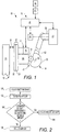
- Figure 1 a simplified example of an actuation mechanism 42 is shown in Figure 1 that includes an operating shaft 60, a linkage 62, a roller 64, and an actuator unit 66.
- the actuator 40 may be operatively connected to an operating shaft 60.
- the actuator 40 is indirectly connected to the operating shaft 60 via the linkage 62, which may also be called an operating lever.
- the linkage 62 may be coupled to the actuator rod 50.
- extending the actuator rod 50 may cause the operating shaft 60 to rotate about an axis 68 due to interaction with a roller 64.
- the roller 64 may transmit force to the brake pad assemblies 22 via the actuator unit 66, which may include more pistons in a manner known by those skilled in the art.
- Movement of the actuator 40 from the first position to the second position may cause the actuator rod 50 to move left from the position shown in Figure 1 . Movement of the actuator rod 50 may transmit the input force to the operating shaft 60 via the linkage 62 and may cause the operating shaft 60 to rotate counterclockwise about the axis 68 and/or roller 64 from the perspective shown. The output force may then be transmitted to actuate a brake pad assembly 22 from the retracted position to the extended position by the actuator unit 66. In a floating caliper configuration, an inboard brake pad assembly 22 may engage the brake friction member 20 before and outboard brake pad assembly (not shown).
- a reaction force (which is substantially equal to the output force) may be transmitted to the outboard brake pad assembly to pull the outboard brake pad assembly against the brake friction member 20 via movement of the floating caliper housing when the inboard brake pad assembly 22 has engaged the brake friction member 20.
- the inboard and outboard brake pad assemblies 22 may cooperate to engage and brake or inhibit rotation of the brake friction member 20.
- the actuation mechanism components may return to their initial positions, or starting positions when a brake command ends and the actuator 40 is permitted to move from the second position to the first position (e.g., the actuator rod 50 is permitted to back to its initial position).
- the operating shaft 60 may rotate in a first direction when a brake pedal is actuated and may rotate in a second direction disposed opposite the first direction when the brake pedal is released.
- the air gap adjustment mechanism 44 may be provided to adjust the air gap to compensate for friction material wear or air gap or clearance changes that may be due to temperature change or other factors.
- the air gap adjustment mechanism 44 may include an adjustment motor 70.
- the adjustment motor 70 may have any suitable configuration.
- the adjustment motor 70 may be an electric motor and may include an encoder that may be configured to measure displacement or rotation of a motor shaft to facilitate monitoring and control of the adjustment motor 70.
- the adjustment motor 70 may be connected to components that may establish or set the retracted position or rest position of a brake pad assembly 22.
- the adjustment motor 70 may be operatively connected to a tappet that may be provided with or associated with the actuator unit 66.
- the tappet may receive the piston of the actuator unit 66 and may have threads that interact with corresponding threads on the piston to permit or inhibit relative rotation to adjust the air gap in a manner known by those skilled the art. Operation of the adjustment motor 70 may be controlled by the control system 16.
- the control system 16 may be configured to monitor and/or control operation of the brake system 10.
- the control system 16 may include one or more control modules or controllers 80 that may be provided to monitor and control various components. For simplicity, a single controller is shown in Figure 1 ; however, it is contemplated that multiple control modules or controllers or a distributed control architecture may be provided.
- the controller 80 may monitor and control the actuator subsystem 14, air gap adjustment mechanism 44 and its adjustment motor 70, and the amount of brake torque provided by the friction brakes 12.
- the controller 80 may also process input signals or data from various input devices or sensors such as a brake pedal sensor 82 and an actuation mechanism position sensor 84.
- a brake pedal sensor 82 may be provided to detect a braking command or a brake torque command that may be provided by a vehicle driver or vehicle operator.
- the brake pedal sensor 82 may detect the position of a brake pedal 90 or the position or operating state of a component that may be connected to or operated by a brake pedal, such as a treadle valve that may modulate a control fluid pressure that may be provided to a relay valve that may control the supply of fluid to one or more friction brakes 12 or friction brake actuators.
- the brake pedal sensor 82 may be configured as a pressure sensor that may detect fluid pressure that may directly or indirectly control the actuator 40 or braking of the vehicle. The detected position of the brake pedal and/or detected pressure may be used to control the brake torque provided by the brake system 10.
- the controller 80 may control operation of a valve that controls fluid pressure provided to a friction brake 12, a brake pump that pressurizes fluid, and/or an electric motor that may actuate a brake pad assembly 22.
- the amount of brake torque provided by the brake system 10 may be proportional to a detected angle of motion or amount of actuation of the brake pedal 90 or other brake torque command input device.
- the actuation mechanism position sensor 84 which is also referred to as a position sensor, may detect rotation of the operating shaft 60. As such, the actuation mechanism position sensor 84 may provide a signal or data that may be indicative of rotation of the operating shaft 60 about the axis 68.
- the actuation mechanism position sensor 84 may be of any suitable type.
- the actuation mechanism position sensor 84 may be an encoder.
- control logic may be implemented or affected in hardware, software, or a combination of hardware and software.
- the various functions may be affected by a programmed microprocessor.
- the control logic may be implemented using any of a number of known programming and processing techniques or strategies and is not limited to the order or sequence illustrated. For instance, interrupt or event-driven processing may be employed in real-time control applications rather than a purely sequential strategy as illustrated. Likewise, parallel processing, multitasking, or multi-threaded systems and methods may be used.
- Control logic may be independent of the particular programming language, operating system, processor, or circuitry used to develop and/or implement the control logic illustrated. Likewise, depending upon the particular programming language and processing strategy, various functions may be performed in the sequence illustrated, at substantially the same time, or in a different sequence while accomplishing the method of control. The illustrated functions may be modified, or in some cases omitted, without departing from the scope of the present invention. In at least one embodiment, a method may be executed by the controller 80 and may be implemented as a closed loop control system.
- the method may indirectly estimate the size or width of the air gap 34 between the brake friction member 20 and a brake pad assembly 22 and may control or adjust the air gap as appropriate.
- the width of the air gap 34 may not be directly detected by a sensor or other device that may directly measure the distance from the brake friction member 20 and a brake pad assembly 22 when the brake pad assembly 22 is in the retracted position. Indirect estimation of the air gap may be affected by various factors that may lead to inaccurate air gap estimates.
- indirect estimation of the air gap may be affected by multiple factors associated with the characteristics of the actuator subsystem 14 (wear, component expansion, component contraction, tolerance variations, vibrations, noise, position sensor bias and drift, etc.), which may be further affected by environmental factors (e.g., temperature which may cause component expansion or contraction, contaminants, etc.).
- environmental factors e.g., temperature which may cause component expansion or contraction, contaminants, etc.
- noise and disturbance during air gap detection, nonlinearity of the position sensor signal, and time delay in air gap adjustment may also influence air gap estimates. The method discussed below may help provide more accurate air gap estimates and control of the air gap.
- the method may cycle the friction brake and obtain data or a signal from the actuation mechanism position sensor 84.
- the friction brake may be cycled when vehicle braking is desired or requested.
- a request for braking may be based on data or a signal from the brake pedal sensor 82.
- a request for braking may also be automatically initiated or automatically requested rather than manually requested.
- braking of the vehicle may be automatically initiated by an adaptive cruise control system or pre-impact collision avoidance system.
- An adaptive cruise control system may automatically adjust vehicle speed in response to the proximity and/or relative speed of another vehicle. As such, an adaptive cruise control system may brake the vehicle to adjust proximity and/or vehicle speed.
- a pre-impact collision avoidance system may be configured to detect a potential collision or impact with the vehicle before it occurs and brake or slow the vehicle to avoid a collision. Cycling the friction brake may include actuating one or more brake pad assemblies 22 from the retracted position to the extended position (i.e., into engagement with the brake friction member 20) and releasing the brake pad assembly 22 such that the brake pad assembly 22 disengages the brake friction member 20 and moves back to or toward the retracted position.
- the actuation mechanism position sensor 84 may detect rotation of the operating shaft 60 during cycling of the friction brake 12. As such, a signal or data from the actuation mechanism position sensor 84 may detect movement or the absence of movement of a brake pad assembly 22.
- An example of an exemplary signal from the actuation mechanism position sensor 84 is shown in Figure 4 and will be discussed in more detail below with the flowchart in Figure 3 .
- the air gap (i.e., air gap size or width) may be estimated.
- the size or width of the air gap 34 may be estimated based on the signal or data from the actuation mechanism position sensor 84 and from the output force generated.
- the estimated size or width of the air gap 34 may be referred to as the estimated air gap.
- the estimated air gap is compared to a desired air gap, which may also be referred to as a threshold air gap.
- the estimated air gap may be based on the signal from the actuation mechanism position sensor 84 and from the output force generated as previously discussed.
- the desired air gap may be a predetermined value and may be based on the configuration of the brake system and/or vehicle development testing.
- the desired air gap may be indicative of an air gap width or distance beyond which the brake pad assembly 22 and its friction material 32 is not sufficiently close to the brake friction member 20 when in the retracted position.
- the desired air gap may be indicative of an air gap width or distance at which the brake pad assembly 22 and its friction material 32 is too close to the brake friction member 20 when in the retracted position.
- the desired air gap may be expressed as a single value but may incorporate a tolerance range.
- the desired air gap may be expressed as a value like 0.6 mm, but may have a tolerance of +/- 0.05 mm, which thereby expresses the desired air gap as a range from 0.55 mm to 0.65 mm.
- the desired air gap may be a range rather than a single absolute value. If the estimated air gap is sufficiently close to the desired air gap, then the method may continue at block 106. If the estimated air gap is not sufficiently close to the desired air gap, then the method may continue at block 108.
- the air gap may not be adjusted.
- the air gap may not be adjusted since the estimated air gap indicates that the friction material 32 of at least one brake pad assembly 22 is sufficiently close to the brake friction member 20 when in the retracted position to provide a desired braking performance.
- the air gap may not be adjusted when the estimated air gap indicates that the friction material 32 of at least one brake pad assembly 22 is sufficiently distant or not too close to the brake friction member 20 when in the retracted position. As such, the retracted position may not be adjusted.
- the air gap may be adjusted.
- the air gap may be reduced by operating the air gap adjustment mechanism 44 to move one or more brake pad assemblies 22 closer to the brake friction member 20 when the estimated air gap is greater than the desired air gap.
- the retracted position of a brake pad assembly 22 may be changed such that the brake pad assembly 22 is moved closer to the brake friction member 20 than the previous retracted position or before making the air gap adjustment.
- the air gap may be increased by operating the air gap adjustment mechanism 44 to move one or more brake pad assemblies 22 further from the brake friction member 20 when the estimated air gap is less than the desired air gap.
- the retracted position of a brake pad assembly 22 may be changed such that the brake pad assembly 22 is moved further from the brake friction member 20 than the previous retracted position or before making the air gap adjustment.
- the air gap adjustment may be initiated or may occur during release of the brake pad assembly 22, or while the brake pad assembly 22 is moving from the extended position toward the retracted position.
- the air gap 34 may be adjusted by operating the adjustment motor 70 to actuate the air gap adjustment mechanism 44 and set the retracted position closer to the brake friction member 20. The amount of adjustment may be based on the difference between the estimated air gap and the desired air gap.
- the magnitude of the difference may then be used to determine a number of adjustment motor revolutions or length of time to activate the adjustment motor 70 to reduce the air gap to a desired amount or distance.
- the distance or amount of brake pad movement per revolution of the adjustment motor 70 may be calculated or may be a predetermined amount that in turn may be used to determine how long to activate the adjustment motor 70 or how many motor shaft revolutions may be sufficient to reduce the air gap.
- FIG. 4-7 a flowchart is shown that provides more detail regarding estimation of the air gap.
- the flowchart in Figure 3 is best understood with reference to Figures 4-7 .
- the rotational position of the operating shaft 60 detected by the actuation mechanism position sensor 84 is plotted on the vertical axis.
- the vertical axis may be depicted in any suitable units that may represent angular motion, such as degrees.
- units of measurement employed by the actuation mechanism position sensor 84 e.g., encoder units
- Time (t) is measured along the horizontal axis.
- Figures 5-7 show the signal from the position sensor during and after processing.
- a signal from the actuation mechanism position sensor 84 before processing From time 0 to time 1, the operating shaft may not rotate. Thus, the actuation mechanism position sensor 84 may not detect rotation of the operating shaft during this time period. As such, the signal may be expected to extend along the time axis (i.e., the actuation mechanism position sensor 84 may be expected to have a reading of zero); however, the signal is shown with a negative signal drift from the time axis (i.e., the entire signal is offset downward or negatively from the expected position) which may result from one or more of the factors previously discussed. Cycling of the friction brake is shown between time 1 (t 1 ) and time 4 (t 4 ).
- the signal may increase from time 1 (t 1 ) to time 2 (t 2 ) at a first slope or with a first curvature, which may be indicative of actuation of one or more brake pad assemblies toward the brake friction member. From time 2 (t 2 ) to time 3 (t 3 ), the brake pad assembly may be in engagement with the brake friction member such that there is no air gap. As such, it would be expected that the signal would not change (i.e., the signal would be horizontal and constant); however, the signal is shown with a second slope or second curvature which may result from signal error and/or one or more of the mechanical and/or environmental factors previously discussed.
- the signal may decrease from time 3 (t 3 ) to time 4 (t 4 ) at a third slope or with a third curvature, which may be indicative of disengagement of one or more brake pad assemblies toward the brake friction member.
- the actuation mechanism position sensor 84 does not detect rotation of the operating shaft.
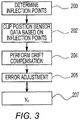
- the method determines inflection points associated with the signal.
- the inflection points may be determined by interpolation or any suitable signal processing technique.
- a first inflection point I 1 is located at time 2 (t 2 ).
- the first inflection point I 1 may be indicative of engagement of the brake pad assembly with the brake friction member.
- a second inflection point I2 is located at time 3 (t 3 ).
- the second inflection point I 2 may be indicative of release of the brake pad assemblies or disengagement of the brake pad assemblies from the brake friction member.
- the first inflection point I 1 may or may not have the same magnitude as the second inflection point I 2 .
- the position sensor signal may be clipped. Clipping the signal from a position sensor may be based on the first and second inflection points. More specifically, the signal may be clipped to the time value that corresponds with the first inflection point I 1 and may be clipped to the time value that corresponds with the second inflection point I 2 . This is best shown in Figure 5 . In Figure 5 , the signal is clipped such that the signal is a vertical line at time 2 (t 2 ) from the horizontal line (originally shown from time 0 to time 1) to the first inflection point I 1 . Similarly, the signal is clipped such that the signal is a vertical line at time 3 (t 3 ) from the second inflection point I 2 to the horizontal line.
- the method may perform drift compensation.
- Drift compensation may occur after clipping the signal at block 202.
- Drift compensation may compensate or correct for the drift or non-zero signal that would otherwise be expected when the friction brake is not actuated or cycled.
- Drift compensation is best understood by comparing Figure 5 to Figure 6 .
- the entire clipped signal in Figure 5 is adjusted such that the encoder measurement is set to zero when the friction brake is not actuated.
- the entire position sensor signal may be adjusted upward (when there is negative signal drift) or downward (if there is positive signal drift) so that the signal is set to zero before the first inflection point I 1 and/or after the second inflection point I 2 .
- the amount of signal drift shown in Figure 5 is designated D.
- Drift compensation may be based on a drift measurement.
- Drift measurement may be based on an actual or physical measurement.
- drift compensation may be based on drift measurement data from an absolute position sensor that may directly detecting or measure the width of the air gap.
- drift compensation may be based on an estimated drift measurement provided by a model-based system in which brake pressure and or brake temperature may be used to model or determine an estimated drift amount.
- Error adjustment may adjust the signal to a constant value between the first inflection point I 1 and the second inflection point I 2 .
- Such adjustments may be based on a reasoning process that may employ fuzzy logic. Error adjustment is best shown by comparing Figures 5 and 6 .
- the shaded area is the error area.
- the error area may represent a signal region where a stable constant (horizontal) signal is expected and may be bounded by the signal located between the first inflection point I 1 and the second inflection point I 2 , or a straight line that may extend from I 1 to I 2 .
- a centroid or geometrical center of the error area may be determined in any suitable manner, such as by integration of the signal curve between and above I 1 and I 2 in the example shown in Figure 5 .
- the centroid may be similar to a "center of mass" of the error area.
- the centroid may include a time axis coordinate and an encoder axis coordinate.
- the centroid is represented by the letter C and has an encoder axis (vertical axis) coordinate of y c .
- Encoder axis centroid and more particularly the encoder axis coordinate may be used to level the signal.
- the signal is adjusted such that the signal is set to a constant value that corresponds to y c between time 2 (t 2 ) and time 3 (t 3 ) (e.g., between I 1 and I 2 ).
- time 3 (t 3 ) coordinate y c may be stored e.g. at block 207 or maintained until the next brake action.
- the pressure of fluid in the actuator 40 has been plotted against time in respect of a brake cycle.
- the pressure in actuator 40 can be sensed by the brake pedal sensor 82 which has been configured as a pressure sensor (as described above) to detect the pressure of fluid in the actuator 40. From time zero to ta, there is no pressure in the actuator and hence the brake does not generate any braking torque since the brake pad assembly 22 is spaced from the brake friction member 20. Between times t a and t c the pressure in the actuator 40 progressively increases to a maximum Pmax (in this case 8 bar) Between time ta and t c the brake pad assembly 22 moves into engagement with the brake friction member 22 and applies an output force to brake friction member 20 thereby creating a brake torque.
- Pmax in this case 8 bar
- the brake pad assembly engages the friction member, and in this example this occurs at t b .
- the relationship between the pressure in the actuator and the output force generated by the brake system is known and thus the pressure in the actuator 40 is indicative of an amount of output force generated by the actuator sub system 14.
- the pressure in the actuator 40 remains at 8 bar until time t d when the fluid (typically air) is vented from the actuator and the pressure decays to zero at time t f wherein the brake pad assembly 22 has returned to the position shown in figure 1 , i.e. a gap 34 exists between the brake pad assembly 22 and the bake friction member 20.
- the brake pad assembly 22 will disengage from the friction member 20, and in this example this is at time t e .
- the gap between the brake pad assembly 22 and the brake friction member 20 is progressively increasing.
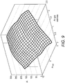
- Figure 9 shows a three dimensional contour map of relationship between y c , Pmax and the air gap. This relationship is based on the particular configuration of the brake system 10 and it's particular components and the relationship can be determined during the design and development of the particular brake system. For a particular brake system there is a predefined relationship between y c , Pmax and the air gap. This relationship can be defined via map or contour as shown in figure 9 , and/or via a look up table, and/or via an algorithm and/or via a database.
- the air gap estimate can be determined from figure 9 .
- the estimate air gap in block 102 of figure 2 is determined from figure 9 .
- a method described from thereon in figure 2 can be used to either adjust the air gap if adjustment is necessary or not to adjust the air gap if no adjustment is necessary.
- Pmax is indicative of an amount of output force generated by the actuator sub system 14 during the braking cycle.
- Pmax is indicative of an amount of output force generated by the actuator sub system 14 during the braking cycle.
- the pressure in the actuator 40 is indicative of an amount of output force generated but other parameters of the brake system are indicative of an amount of output force generated.
- the force applied to a brake pedal is indicative of an amount of output force generated
- the amount of bending in the linkage 62 is indicative of an amount of output force generated
- the compression in actuator rod 50 is indicative of an amount of output force generated as are other measurable parameters.
- the above mentioned output force is a brake force used to engage the brake pad assembly with the brake friction member.
- the input force exerted by the actuator 40 is a brake force that is used to engage the brake pad assembly with the brake friction member and the pressure in the actuator is a signal indicative of the amount of input force.
- the force applied to the brake pedal is a brake force that is used to engage the brake pad assembly with the brake friction member and the force applied by a brake pedal can be measured by a sensor.
- the brake force causes the linkage 62 to bend and the brake force causing the linkage 62 to bend can be measured by a sensor.
- the compression in actuator rod 50 is a brake force used to engage the brake pad assembly with the brake friction member and the brake force causing compression of actuator rod 50 can be measured by a sensor.
- the present invention is applicable to any brake force used to engage the brake pad assembly with a brake friction member.
- the present invention is applicable to any type of further signal which is indicative of an amount of any type of brake force used to engage the brake pad assembly with a brake friction member.
Landscapes
- Engineering & Computer Science (AREA)
- General Engineering & Computer Science (AREA)
- Mechanical Engineering (AREA)
- Transportation (AREA)
- Regulating Braking Force (AREA)
- Braking Arrangements (AREA)
Claims (15)
- Verfahren zur Steuerung eines Bremssystems (10), das Folgendes umfasst:Betätigen und Lösen einer Reibungsbremse (12);indirektes Schätzen eines Luftspalts (34) zwischen einem Bremsreibungselement (20) und einer Bremsbelaganordnung (22), basierend auf einem Positionssignal von einem Positionssensor (84), der Betätigen und Lösen der Reibungsbremse (12) detektiert, und einem weiteren Signal, das indikativ für einen Betrag von Bremskraft ist, die verwendet wird, um die Bremsbelaganordnung (22) mit dem Bremsreibungselement (20) in Eingriff zu bringen; undEinstellen des Luftspalts (34), wenn ein geschätzter Luftspalt von einem gewünschten Luftspalt verschieden ist, wobei das weitere Signal indikativ für einen Druck in einem Aktuator (40) während des Betätigens und Lösens der Reibungsbremse (12) ist.
- Verfahren nach Anspruch 1, wobei der Positionssensor (84) Rotation einer operativen Welle (60) während des Betätigens und Lösens der Reibungsbremse (12) detektiert.
- Verfahren nach Anspruch 1, wobei Betätigen und Lösen der Reibungsbremse (12) ferner Betätigen der Bremsbelaganordnung (22) aus einer eingezogenen Position, in der die Bremsbelaganordnung (22) vom Bremsreibungselement (20) beabstandet ist, in Eingriff mit dem Bremsreibungselement (20) und Lösen der Bremsbelaganordnung (22), sodass die Bremsbelaganordnung (22) vom Bremsreibungselement (20) getrennt wird, umfasst.
- Verfahren nach Anspruch 3, wobei Einstellen des Luftspalts (34) ferner Betreiben eines Einstellmotors (70) zum Ändern der eingezogenen Position umfasst, sodass die Bremsbelaganordnung (22) näher an dem Bremsreibungselement (20) angeordnet ist, oder wobei das Verfahren ferner Einstellen des Luftspalts (34), wenn ein geschätzter Luftspalt kleiner als ein gewünschter Luftspalt ist, durch Betreiben eines Einstellmotors (70) zum Ändern der eingezogenen Position umfasst, sodass die Bremsbelaganordnung (22) weiter vom Bremsreibungselement (20) angeordnet ist, oder wobei Einstellen des Luftspalts (34) während des Lösens der Bremsbelaganordnung (22) auftritt.
- Verfahren nach Anspruch 1, ferner umfassend Nicht-Einstellen des Luftspalts (34), wenn der geschätzte Luftspalt hinreichend nahe an dem gewünschten Luftspalt ist.
- Verfahren zur Steuerung eines Bremssystems (10), das Folgendes umfasst:Betätigen und Lösen einer Reibungsbremse (12) durch Betätigen einer Bremsbelaganordnung (22) aus einer eingezogenen Position in Eingriff mit einem Bremsreibungselement (20) und Lösen der Bremsbelaganordnung (22), sodass die Bremsbelaganordnung vom Bremsreibungselement (20) getrennt wird und sich zur eingezogenen Position bewegt;indirektes Schätzen eines Luftspalts (34) zwischen einem Bremsreibungselement (20) und der Bremsbelaganordnung (22), basierend auf einem Positionssignal von einem Positionssensor, das indikativ für eine Betätigung des Bremspedals (90) ist, und einem weiteren Signal, das indikativ für einen Betrag von Bremskraft ist, die verwendet wird, um die Bremsbelaganordnung (22) mit dem Bremsreibungselement (20) in Eingriff zu bringen; undEinstellen des Luftspalts (34), wenn ein geschätzter Luftspalt von einem gewünschten Luftspalt verschieden ist, wobei das weitere Signal indikativ für einen Druck in einem Aktuator (40) während des Betätigens und Lösens der Reibungsbremse (12) ist.
- Verfahren nach Anspruch 6, wobei indirektes Schätzen des Luftspalts (34) Abschneiden des Positionssignals vom Positionssensor durch Bestimmen eines ersten Wendepunkts (I1) und eines zweiten Wendepunkts (I2) des Signals und Abschneiden des Signals auf einen ersten Zeitwert, der dem ersten Wendepunkt (I1) entspricht, und auf einen zweiten Zeitwert, der dem zweiten Wendepunkt (I2) entspricht, umfasst.
- Verfahren nach Anspruch 7, wobei der erste Wendepunkt (I1) indikativ für einen Eingriff der Bremsbelaganordnung (22) mit dem Bremsreibungselement (20) ist oder wobei der zweite Wendepunkt (I2) indikativ für ein Trennen der Bremsbelaganordnung (22) vom Bremsreibungselement (20) ist.
- Verfahren nach Anspruch 7, wobei indirektes Schätzen des Luftspalts (34) ferner Einstellen des Positionssignals zum Kompensieren einer Drift nach Abschneiden des Signals umfasst.
- Verfahren nach Anspruch 9, wobei indirektes Schätzen des Luftspalts (34) ferner Durchführen einer Fehleranpassung durch Bestimmen eines Schwerpunkts (C) eines Fehlerbereichs, angeordnet zwischen dem ersten Wendepunkt (I1) und dem zweiten Wendepunkt (I2), und Einstellen des Positionssignals, basierend auf dem Schwerpunkt des Fehlerbereichs, umfasst, wobei Durchführen der Fehleranpassung vorzugsweise Einstellen des Positionssignals auf einen konstanten Wert zwischen dem ersten Wendepunkt und dem zweiten Wendepunkt umfasst, wobei Durchführen der Fehleranpassung vorzugsweise auf Unschärfelogik basiert.
- Bremssystem (10), das Folgendes umfasst:ein Bremsreibungselement (20);eine Bremsbelaganordnung (22), dazu ausgelegt, sich zwischen einer eingezogenen Position, in der die Bremsbelaganordnung (22) nicht in das Bremsreibungselement (20) eingreift, und einer ausgezogenen Position, in der die Bremsbelaganordnung (22) in das Bremsreibungselement (20) eingreift, zu bewegen;ein Aktuatoruntersystem (14), das eine operative Welle (60) umfasst, die rotiert, wenn sich die Bremsbelaganordnung (22) zwischen der eingezogenen Position und der ausgezogenen Position bewegt; undeinen Positionssensor (84), der Rotation der operativen Welle (60) detektiert;wobei ein Luftspalt (34) zwischen der Bremsbelaganordnung (22) und dem Bremsreibungselement (20) geschätzt wird, basierend auf einem Positionssignal vom Positionssensor und einem Signal, das indikativ für einen Betrag von Bremskraft ist, die verwendet wird, um die Bremsbelaganordnung (22) mit dem Bremsreibungselement (20) in Eingriff zu bringen, wobei das Signal indikativ für einen Druck in einem Aktuator (40) während des Betätigens und Lösens der Reibungsbremse (12) ist.
- Bremssystem (10) nach Anspruch 11, wobei das Positionssignal vom Positionssensor erhalten wird, wenn sich die Bremsbelaganordnung (22) aus der eingezogenen Position in die ausgezogene Position und zurück in die eingezogene Position bewegt oder wobei das Bremssystem (10) ferner einen Einstellmotor (70) umfasst, wobei der Einstellmotor (70) die Bremsbelaganordnung (22) näher an das Bremsreibungselement (20) bewegt, um den Luftspalt (34) zu verringern, wenn ein geschätzter Luftspalt, der auf dem Signal vom Positionssensor basiert, einen gewünschten Luftspalt (34) überschreitet, oder wobei das Bremssystem (10) ferner einen Einstellmotor (70) umfasst, wobei der Einstellmotor (70) die Bremsbelaganordnung (22) weiter vom Bremsreibungselement (20) bewegt, um den Luftspalt (34) zu vergrößern, wenn ein geschätzter Luftspalt (34), der auf dem Signal vom Positionssensor basiert, einen gewünschten Luftspalt (34) nicht überschreitet, oder wobei ein Einstellmotor (70) den Luftspalt (34) einstellt, wenn sich die Bremsbelaganordnung (22) von der ausgezogenen Position in Richtung der eingezogenen Position bewegt und wobei der Einstellmotor (70) nicht die Bremsbelaganordnung (22) von der eingezogenen Position in die ausgezogene Position bewegt.
- Verfahren nach Anspruch 1, wobei das weitere Signal indikativ für einen maximalen Druck im Aktuator (40) während des Betätigens und Lösens der Reibungsbremse (12) ist.
- Verfahren nach Anspruch 1, wobei das weitere Signal indikativ für eine Kraft in einer Komponente des Bremssystems (10) ist.
- Verfahren nach Anspruch 1, wobei der Schritt des indirekten Schätzens des Luftspalts (34) Bestimmen einer vorbestimmten Beziehung zwischen dem Positionssignal, dem weiteren Signal und dem Luftspalt (34) und Bestimmen, aus dem Positionssignal, dem weiteren Signal und der vorbestimmten Beziehung, der Schätzung des Luftspalts (34) umfasst, wobei die Beziehung vorzugsweise durch zumindest eines aus einer Zuordnung, einer Nachschlagtabelle, einem Algorithmus und einer Datenbank definiert ist.
Priority Applications (2)
| Application Number | Priority Date | Filing Date | Title |
|---|---|---|---|
| EP16172941.3A EP3251908B1 (de) | 2016-06-03 | 2016-06-03 | Bremssystem und verfahren zur steuerung mit luftspaltschätzung |
| US15/484,572 US10422396B2 (en) | 2016-06-03 | 2017-04-11 | Brake system and method of control with air gap estimation |
Applications Claiming Priority (1)
| Application Number | Priority Date | Filing Date | Title |
|---|---|---|---|
| EP16172941.3A EP3251908B1 (de) | 2016-06-03 | 2016-06-03 | Bremssystem und verfahren zur steuerung mit luftspaltschätzung |
Publications (2)
| Publication Number | Publication Date |
|---|---|
| EP3251908A1 EP3251908A1 (de) | 2017-12-06 |
| EP3251908B1 true EP3251908B1 (de) | 2021-01-20 |
Family
ID=56108545
Family Applications (1)
| Application Number | Title | Priority Date | Filing Date |
|---|---|---|---|
| EP16172941.3A Active EP3251908B1 (de) | 2016-06-03 | 2016-06-03 | Bremssystem und verfahren zur steuerung mit luftspaltschätzung |
Country Status (2)
| Country | Link |
|---|---|
| US (1) | US10422396B2 (de) |
| EP (1) | EP3251908B1 (de) |
Families Citing this family (9)
| Publication number | Priority date | Publication date | Assignee | Title |
|---|---|---|---|---|
| DE102016223826A1 (de) * | 2016-11-30 | 2018-05-30 | Robert Bosch Gmbh | Verfahren und Vorrichtung zum Betreiben eines hydraulischen Bremssystems, Bremssystem |
| AT520073B1 (de) * | 2017-10-05 | 2019-01-15 | Ve Vienna Engineering Forschungs Und Entw Gmbh | Verfahren und Bremsensteuerung zum Betätigen einer Reibungsbremse |
| US11077837B2 (en) * | 2018-12-12 | 2021-08-03 | Continental Automotive Systems, Inc. | Cruise control cancel, with brake precharge |
| AT522040B1 (de) * | 2018-12-17 | 2020-11-15 | Greenbrakes Gmbh | Elektromechanische Bremsenanlage |
| DE102019100183A1 (de) * | 2019-01-07 | 2020-07-09 | Wabco Europe Bvba | Verfahren zum Ermitteln eines Lüftspiels einer elektromechanischen Bremse sowie betreffende Bremse und Steuergerät |
| DE102019100481A1 (de) * | 2019-01-10 | 2020-07-16 | Wabco Europe Bvba | Verfahren zum Einstellen eines Lüftspiels einer elektromechanischen Bremse sowie betreffende Bremse und Steuergerät |
| US12325331B2 (en) * | 2021-06-04 | 2025-06-10 | Tusas—Turk Havacilik Ve Uzay Sanayii Anonim Sirketi | Brake system |
| KR20240115615A (ko) | 2023-01-19 | 2024-07-26 | 에이치엘만도 주식회사 | 전기 기계식 브레이크 및 그 제어 방법 |
| US20260084676A1 (en) * | 2024-09-20 | 2026-03-26 | Ford Global Technologies, Llc | Methods and apparatus to monitor a condition of a braking system |
Family Cites Families (25)
| Publication number | Priority date | Publication date | Assignee | Title |
|---|---|---|---|---|
| DE4017950A1 (de) | 1990-06-05 | 1991-12-12 | Wabco Westinghouse Fahrzeug | Bremsbetaetigungseinrichtung mit einer einrichtung zum nachstellen einer bremse |
| US5285190A (en) | 1991-11-04 | 1994-02-08 | Onboard Systems Limited | Automatic slack adjuster with operation and adjustment monitor |
| US5432442A (en) | 1993-07-30 | 1995-07-11 | Itt Corporation | Speed sensor including output signal proportional to air gap size |
| DE19536695A1 (de) | 1995-09-30 | 1997-04-03 | Teves Gmbh Alfred | System zum Steuern oder Regeln einer elektromechanischen Bremse |
| GB9823199D0 (en) | 1998-10-24 | 1998-12-16 | Lucas Ind Plc | Vehicle brake having brake de-adjust |
| DE19730094A1 (de) | 1997-07-14 | 1999-01-21 | Itt Mfg Enterprises Inc | System zum Steuern oder Regeln einer elektromechanischen Bremse |
| GB9823198D0 (en) | 1998-10-24 | 1998-12-16 | Lucas Ind Plc | Vehicle brake having electric motor control of brake running clearance |
| DE10138452B4 (de) | 2001-08-04 | 2014-07-17 | Wabco Gmbh | Verfahren zur Lüftspielnachstellung von Scheibenbremsen |
| DE10228115B4 (de) | 2002-06-24 | 2004-05-13 | Lucas Automotive Gmbh | Elektrisch betätigbare Fahrzeugbremse und Verfahren zur Steuerung einer elektrisch betätigbaren Fahrzeugbremse |
| US7726748B2 (en) | 2005-09-26 | 2010-06-01 | Zumberge Jon T | Low force level detection system and method |
| US20070235267A1 (en) | 2006-04-11 | 2007-10-11 | Goodrich Corporation | Controller for electromechanical braking system with running clearance adjustment and method |
| DE102006029699B4 (de) | 2006-06-28 | 2009-09-03 | Lucas Automotive Gmbh | Verfahren zum Bestimmen des Verschleißzustandes von Bremsbelägen an Radbremseinheiten einer Kraftfahrzeugbremsanlage und Kraftfahrzeugbremsanlage |
| DE102007004604A1 (de) | 2007-01-30 | 2008-07-31 | Siemens Ag | Ermittlung des Lüftspiels bei einer Bremse mit zwei Zuspannrichtungen |
| US8220594B2 (en) | 2007-08-30 | 2012-07-17 | Nippon Soken, Inc | Electric brake device |
| EP2225132B1 (de) * | 2007-12-21 | 2011-09-14 | Ipgate Ag | Bremsanlage mit mindestens einer förderungseinrichtung zum nachfördern von bremsflüssigkeit in die arbeitsräume eines bremskraftverstärkers |
| AT508296A1 (de) * | 2009-05-19 | 2010-12-15 | Ve Vienna Engineering Forschungs Und Entwicklungs Gmbh | Reibungsbremse |
| JP5637067B2 (ja) * | 2011-05-24 | 2014-12-10 | 株式会社アドヴィックス | 電動ブレーキ装置および電動ブレーキ装置の制御方法 |
| US9796369B2 (en) * | 2012-01-13 | 2017-10-24 | Toyota Jidosha Kabushiki Kaisha | Hydraulic brake system |
| EP2650556B1 (de) | 2012-03-28 | 2019-10-23 | Meritor Heavy Vehicle Braking Systems (UK) Limited | Bremse |
| AT512683B1 (de) | 2012-04-12 | 2024-12-15 | Bosch Gmbh Robert | Bremssystem und Bremsverfahren für eine elektrisch betätigte, nicht-lineare Reibungsbremse |
| DE102013100786A1 (de) * | 2013-01-25 | 2014-07-31 | Knorr-Bremse Systeme für Nutzfahrzeuge GmbH | Scheibenbremse mit einer Lüftspielüberwachungsvorrichtung und Verfahren zur Lüftspielüberwachung |
| DE102013012104B4 (de) * | 2013-07-12 | 2022-10-06 | Knorr-Bremse Systeme für Nutzfahrzeuge GmbH | Verfahren zum Ermitteln eines Lüftspiels einer Fahrzeugbremse und Fahrzeugbremse mit einer Vorrichtung zur Ermittlung eines Lüftspiels |
| US9457782B2 (en) * | 2014-03-14 | 2016-10-04 | Arvinmeritor Technology, Llc | Brake system and method of control with air gap estimation |
| EP2955408B1 (de) * | 2014-06-13 | 2019-11-20 | Meritor Heavy Vehicle Braking Systems (UK) Limited | Bremskomponentenaustauschsystem und -verfahren |
| EP2998607A1 (de) * | 2014-09-16 | 2016-03-23 | Meritor Heavy Vehicle Braking Systems (UK) Limited | Verfahren und System zur Einstellung des Laufspiels einer Bremskomponente |
-
2016
- 2016-06-03 EP EP16172941.3A patent/EP3251908B1/de active Active
-
2017
- 2017-04-11 US US15/484,572 patent/US10422396B2/en active Active
Non-Patent Citations (1)
| Title |
|---|
| None * |
Also Published As
| Publication number | Publication date |
|---|---|
| US20170350462A1 (en) | 2017-12-07 |
| EP3251908A1 (de) | 2017-12-06 |
| US10422396B2 (en) | 2019-09-24 |
Similar Documents
| Publication | Publication Date | Title |
|---|---|---|
| EP3251908B1 (de) | Bremssystem und verfahren zur steuerung mit luftspaltschätzung | |
| EP2927068B1 (de) | Bremssystem und Verfahren zur Steuerung mit Luftspaltschätzung | |
| CN105264254B (zh) | 用于操作电操作的摩擦制动器的方法 | |
| KR102616979B1 (ko) | 마찰 브레이크를 작동하기 위한 방법 및 브레이크 제어 장치 | |
| US8430213B2 (en) | Electric brake | |
| US8833526B2 (en) | Electric brake apparatus | |
| US8336969B2 (en) | Brake apparatus | |
| US8197016B2 (en) | Brake fill effect minimization function | |
| KR101501533B1 (ko) | 전기기계 브레이크의 마모 보상을 위한 모터 제어 시스템 및 그 제어 방법 | |
| KR20180040677A (ko) | 서비스 브레이크의 상태 모니터링을 위한 방법 및 장치 그리고 브레이크 및 브레이크 시스템 | |
| KR20140036303A (ko) | 브레이크 시스템을 동작시키는 방법 및 브레이크 시스템 | |
| CN113015862A (zh) | 电动制动器及控制装置 | |
| US11639159B2 (en) | Method and device for operating an automated parking brake | |
| US12409817B2 (en) | Brake control device and brake control method | |
| CN119677656A (zh) | 用于检测制动器状态的方法、制动器和具有制动器的制动系统 | |
| JP5746319B2 (ja) | 自動化されたクラッチの制御方法 | |
| WO2017005775A1 (en) | Controller, system and method | |
| KR20240174105A (ko) | 전동 브레이크 장치 | |
| CN121316794A (zh) | 用于调节电子机械式车轮制动器中的作用力的方法 | |
| KR20160049203A (ko) | 자동차용 엔진브레이크력 제어 장치 및 방법 |
Legal Events
| Date | Code | Title | Description |
|---|---|---|---|
| PUAI | Public reference made under article 153(3) epc to a published international application that has entered the european phase |
Free format text: ORIGINAL CODE: 0009012 |
|
| STAA | Information on the status of an ep patent application or granted ep patent |
Free format text: STATUS: THE APPLICATION HAS BEEN PUBLISHED |
|
| AK | Designated contracting states |
Kind code of ref document: A1 Designated state(s): AL AT BE BG CH CY CZ DE DK EE ES FI FR GB GR HR HU IE IS IT LI LT LU LV MC MK MT NL NO PL PT RO RS SE SI SK SM TR |
|
| AX | Request for extension of the european patent |
Extension state: BA ME |
|
| STAA | Information on the status of an ep patent application or granted ep patent |
Free format text: STATUS: REQUEST FOR EXAMINATION WAS MADE |
|
| 17P | Request for examination filed |
Effective date: 20180515 |
|
| RBV | Designated contracting states (corrected) |
Designated state(s): AL AT BE BG CH CY CZ DE DK EE ES FI FR GB GR HR HU IE IS IT LI LT LU LV MC MK MT NL NO PL PT RO RS SE SI SK SM TR |
|
| GRAP | Despatch of communication of intention to grant a patent |
Free format text: ORIGINAL CODE: EPIDOSNIGR1 |
|
| STAA | Information on the status of an ep patent application or granted ep patent |
Free format text: STATUS: GRANT OF PATENT IS INTENDED |
|
| INTG | Intention to grant announced |
Effective date: 20200810 |
|
| GRAS | Grant fee paid |
Free format text: ORIGINAL CODE: EPIDOSNIGR3 |
|
| GRAA | (expected) grant |
Free format text: ORIGINAL CODE: 0009210 |
|
| STAA | Information on the status of an ep patent application or granted ep patent |
Free format text: STATUS: THE PATENT HAS BEEN GRANTED |
|
| AK | Designated contracting states |
Kind code of ref document: B1 Designated state(s): AL AT BE BG CH CY CZ DE DK EE ES FI FR GB GR HR HU IE IS IT LI LT LU LV MC MK MT NL NO PL PT RO RS SE SI SK SM TR |
|
| REG | Reference to a national code |
Ref country code: GB Ref legal event code: FG4D |
|
| REG | Reference to a national code |
Ref country code: CH Ref legal event code: EP |
|
| REG | Reference to a national code |
Ref country code: DE Ref legal event code: R096 Ref document number: 602016051602 Country of ref document: DE |
|
| REG | Reference to a national code |
Ref country code: AT Ref legal event code: REF Ref document number: 1356132 Country of ref document: AT Kind code of ref document: T Effective date: 20210215 |
|
| REG | Reference to a national code |
Ref country code: IE Ref legal event code: FG4D |
|
| REG | Reference to a national code |
Ref country code: SE Ref legal event code: TRGR |
|
| REG | Reference to a national code |
Ref country code: NL Ref legal event code: MP Effective date: 20210120 |
|
| REG | Reference to a national code |
Ref country code: LT Ref legal event code: MG9D |
|
| REG | Reference to a national code |
Ref country code: AT Ref legal event code: MK05 Ref document number: 1356132 Country of ref document: AT Kind code of ref document: T Effective date: 20210120 |
|
| PG25 | Lapsed in a contracting state [announced via postgrant information from national office to epo] |
Ref country code: BG Free format text: LAPSE BECAUSE OF FAILURE TO SUBMIT A TRANSLATION OF THE DESCRIPTION OR TO PAY THE FEE WITHIN THE PRESCRIBED TIME-LIMIT Effective date: 20210420 Ref country code: HR Free format text: LAPSE BECAUSE OF FAILURE TO SUBMIT A TRANSLATION OF THE DESCRIPTION OR TO PAY THE FEE WITHIN THE PRESCRIBED TIME-LIMIT Effective date: 20210120 Ref country code: GR Free format text: LAPSE BECAUSE OF FAILURE TO SUBMIT A TRANSLATION OF THE DESCRIPTION OR TO PAY THE FEE WITHIN THE PRESCRIBED TIME-LIMIT Effective date: 20210421 Ref country code: FI Free format text: LAPSE BECAUSE OF FAILURE TO SUBMIT A TRANSLATION OF THE DESCRIPTION OR TO PAY THE FEE WITHIN THE PRESCRIBED TIME-LIMIT Effective date: 20210120 Ref country code: LT Free format text: LAPSE BECAUSE OF FAILURE TO SUBMIT A TRANSLATION OF THE DESCRIPTION OR TO PAY THE FEE WITHIN THE PRESCRIBED TIME-LIMIT Effective date: 20210120 Ref country code: NO Free format text: LAPSE BECAUSE OF FAILURE TO SUBMIT A TRANSLATION OF THE DESCRIPTION OR TO PAY THE FEE WITHIN THE PRESCRIBED TIME-LIMIT Effective date: 20210420 Ref country code: PT Free format text: LAPSE BECAUSE OF FAILURE TO SUBMIT A TRANSLATION OF THE DESCRIPTION OR TO PAY THE FEE WITHIN THE PRESCRIBED TIME-LIMIT Effective date: 20210520 |
|
| PG25 | Lapsed in a contracting state [announced via postgrant information from national office to epo] |
Ref country code: AT Free format text: LAPSE BECAUSE OF FAILURE TO SUBMIT A TRANSLATION OF THE DESCRIPTION OR TO PAY THE FEE WITHIN THE PRESCRIBED TIME-LIMIT Effective date: 20210120 Ref country code: RS Free format text: LAPSE BECAUSE OF FAILURE TO SUBMIT A TRANSLATION OF THE DESCRIPTION OR TO PAY THE FEE WITHIN THE PRESCRIBED TIME-LIMIT Effective date: 20210120 Ref country code: LV Free format text: LAPSE BECAUSE OF FAILURE TO SUBMIT A TRANSLATION OF THE DESCRIPTION OR TO PAY THE FEE WITHIN THE PRESCRIBED TIME-LIMIT Effective date: 20210120 Ref country code: PL Free format text: LAPSE BECAUSE OF FAILURE TO SUBMIT A TRANSLATION OF THE DESCRIPTION OR TO PAY THE FEE WITHIN THE PRESCRIBED TIME-LIMIT Effective date: 20210120 |
|
| PG25 | Lapsed in a contracting state [announced via postgrant information from national office to epo] |
Ref country code: IS Free format text: LAPSE BECAUSE OF FAILURE TO SUBMIT A TRANSLATION OF THE DESCRIPTION OR TO PAY THE FEE WITHIN THE PRESCRIBED TIME-LIMIT Effective date: 20210520 |
|
| REG | Reference to a national code |
Ref country code: DE Ref legal event code: R097 Ref document number: 602016051602 Country of ref document: DE |
|
| PG25 | Lapsed in a contracting state [announced via postgrant information from national office to epo] |
Ref country code: CZ Free format text: LAPSE BECAUSE OF FAILURE TO SUBMIT A TRANSLATION OF THE DESCRIPTION OR TO PAY THE FEE WITHIN THE PRESCRIBED TIME-LIMIT Effective date: 20210120 Ref country code: EE Free format text: LAPSE BECAUSE OF FAILURE TO SUBMIT A TRANSLATION OF THE DESCRIPTION OR TO PAY THE FEE WITHIN THE PRESCRIBED TIME-LIMIT Effective date: 20210120 Ref country code: SM Free format text: LAPSE BECAUSE OF FAILURE TO SUBMIT A TRANSLATION OF THE DESCRIPTION OR TO PAY THE FEE WITHIN THE PRESCRIBED TIME-LIMIT Effective date: 20210120 |
|
| PLBE | No opposition filed within time limit |
Free format text: ORIGINAL CODE: 0009261 |
|
| STAA | Information on the status of an ep patent application or granted ep patent |
Free format text: STATUS: NO OPPOSITION FILED WITHIN TIME LIMIT |
|
| PG25 | Lapsed in a contracting state [announced via postgrant information from national office to epo] |
Ref country code: DK Free format text: LAPSE BECAUSE OF FAILURE TO SUBMIT A TRANSLATION OF THE DESCRIPTION OR TO PAY THE FEE WITHIN THE PRESCRIBED TIME-LIMIT Effective date: 20210120 Ref country code: SK Free format text: LAPSE BECAUSE OF FAILURE TO SUBMIT A TRANSLATION OF THE DESCRIPTION OR TO PAY THE FEE WITHIN THE PRESCRIBED TIME-LIMIT Effective date: 20210120 Ref country code: RO Free format text: LAPSE BECAUSE OF FAILURE TO SUBMIT A TRANSLATION OF THE DESCRIPTION OR TO PAY THE FEE WITHIN THE PRESCRIBED TIME-LIMIT Effective date: 20210120 |
|
| 26N | No opposition filed |
Effective date: 20211021 |
|
| PG25 | Lapsed in a contracting state [announced via postgrant information from national office to epo] |
Ref country code: ES Free format text: LAPSE BECAUSE OF FAILURE TO SUBMIT A TRANSLATION OF THE DESCRIPTION OR TO PAY THE FEE WITHIN THE PRESCRIBED TIME-LIMIT Effective date: 20210120 Ref country code: AL Free format text: LAPSE BECAUSE OF FAILURE TO SUBMIT A TRANSLATION OF THE DESCRIPTION OR TO PAY THE FEE WITHIN THE PRESCRIBED TIME-LIMIT Effective date: 20210120 Ref country code: MC Free format text: LAPSE BECAUSE OF FAILURE TO SUBMIT A TRANSLATION OF THE DESCRIPTION OR TO PAY THE FEE WITHIN THE PRESCRIBED TIME-LIMIT Effective date: 20210120 |
|
| REG | Reference to a national code |
Ref country code: CH Ref legal event code: PL |
|
| PG25 | Lapsed in a contracting state [announced via postgrant information from national office to epo] |
Ref country code: SI Free format text: LAPSE BECAUSE OF FAILURE TO SUBMIT A TRANSLATION OF THE DESCRIPTION OR TO PAY THE FEE WITHIN THE PRESCRIBED TIME-LIMIT Effective date: 20210120 |
|
| REG | Reference to a national code |
Ref country code: BE Ref legal event code: MM Effective date: 20210630 |
|
| PG25 | Lapsed in a contracting state [announced via postgrant information from national office to epo] |
Ref country code: LU Free format text: LAPSE BECAUSE OF NON-PAYMENT OF DUE FEES Effective date: 20210603 |
|
| PG25 | Lapsed in a contracting state [announced via postgrant information from national office to epo] |
Ref country code: LI Free format text: LAPSE BECAUSE OF NON-PAYMENT OF DUE FEES Effective date: 20210630 Ref country code: IT Free format text: LAPSE BECAUSE OF FAILURE TO SUBMIT A TRANSLATION OF THE DESCRIPTION OR TO PAY THE FEE WITHIN THE PRESCRIBED TIME-LIMIT Effective date: 20210120 Ref country code: IE Free format text: LAPSE BECAUSE OF NON-PAYMENT OF DUE FEES Effective date: 20210603 Ref country code: CH Free format text: LAPSE BECAUSE OF NON-PAYMENT OF DUE FEES Effective date: 20210630 |
|
| PG25 | Lapsed in a contracting state [announced via postgrant information from national office to epo] |
Ref country code: IS Free format text: LAPSE BECAUSE OF FAILURE TO SUBMIT A TRANSLATION OF THE DESCRIPTION OR TO PAY THE FEE WITHIN THE PRESCRIBED TIME-LIMIT Effective date: 20210520 |
|
| PG25 | Lapsed in a contracting state [announced via postgrant information from national office to epo] |
Ref country code: BE Free format text: LAPSE BECAUSE OF NON-PAYMENT OF DUE FEES Effective date: 20210630 |
|
| PG25 | Lapsed in a contracting state [announced via postgrant information from national office to epo] |
Ref country code: HU Free format text: LAPSE BECAUSE OF FAILURE TO SUBMIT A TRANSLATION OF THE DESCRIPTION OR TO PAY THE FEE WITHIN THE PRESCRIBED TIME-LIMIT; INVALID AB INITIO Effective date: 20160603 |
|
| PG25 | Lapsed in a contracting state [announced via postgrant information from national office to epo] |
Ref country code: NL Free format text: LAPSE BECAUSE OF NON-PAYMENT OF DUE FEES Effective date: 20210120 Ref country code: CY Free format text: LAPSE BECAUSE OF FAILURE TO SUBMIT A TRANSLATION OF THE DESCRIPTION OR TO PAY THE FEE WITHIN THE PRESCRIBED TIME-LIMIT Effective date: 20210120 |
|
| P01 | Opt-out of the competence of the unified patent court (upc) registered |
Effective date: 20230531 |
|
| PG25 | Lapsed in a contracting state [announced via postgrant information from national office to epo] |
Ref country code: MK Free format text: LAPSE BECAUSE OF FAILURE TO SUBMIT A TRANSLATION OF THE DESCRIPTION OR TO PAY THE FEE WITHIN THE PRESCRIBED TIME-LIMIT Effective date: 20210120 |
|
| PG25 | Lapsed in a contracting state [announced via postgrant information from national office to epo] |
Ref country code: TR Free format text: LAPSE BECAUSE OF FAILURE TO SUBMIT A TRANSLATION OF THE DESCRIPTION OR TO PAY THE FEE WITHIN THE PRESCRIBED TIME-LIMIT Effective date: 20210120 |
|
| PG25 | Lapsed in a contracting state [announced via postgrant information from national office to epo] |
Ref country code: MT Free format text: LAPSE BECAUSE OF FAILURE TO SUBMIT A TRANSLATION OF THE DESCRIPTION OR TO PAY THE FEE WITHIN THE PRESCRIBED TIME-LIMIT Effective date: 20210120 |
|
| PGFP | Annual fee paid to national office [announced via postgrant information from national office to epo] |
Ref country code: DE Payment date: 20250627 Year of fee payment: 10 |
|
| PGFP | Annual fee paid to national office [announced via postgrant information from national office to epo] |
Ref country code: GB Payment date: 20250627 Year of fee payment: 10 |
|
| PGFP | Annual fee paid to national office [announced via postgrant information from national office to epo] |
Ref country code: FR Payment date: 20250625 Year of fee payment: 10 |
|
| PGFP | Annual fee paid to national office [announced via postgrant information from national office to epo] |
Ref country code: SE Payment date: 20250627 Year of fee payment: 10 |