EP1983603B1 - Kühllüfter-steuereinrichtung und verfahren - Google Patents
Kühllüfter-steuereinrichtung und verfahren Download PDFInfo
- Publication number
- EP1983603B1 EP1983603B1 EP06843560.1A EP06843560A EP1983603B1 EP 1983603 B1 EP1983603 B1 EP 1983603B1 EP 06843560 A EP06843560 A EP 06843560A EP 1983603 B1 EP1983603 B1 EP 1983603B1
- Authority
- EP
- European Patent Office
- Prior art keywords
- cooling fan
- power storage
- storage mechanism
- voltage
- control
- Prior art date
- Legal status (The legal status is an assumption and is not a legal conclusion. Google has not performed a legal analysis and makes no representation as to the accuracy of the status listed.)
- Expired - Fee Related
Links
Images


Classifications
-
- B—PERFORMING OPERATIONS; TRANSPORTING
- B60—VEHICLES IN GENERAL
- B60W—CONJOINT CONTROL OF VEHICLE SUB-UNITS OF DIFFERENT TYPE OR DIFFERENT FUNCTION; CONTROL SYSTEMS SPECIALLY ADAPTED FOR HYBRID VEHICLES; ROAD VEHICLE DRIVE CONTROL SYSTEMS FOR PURPOSES NOT RELATED TO THE CONTROL OF A PARTICULAR SUB-UNIT
- B60W20/00—Control systems specially adapted for hybrid vehicles
- B60W20/10—Controlling the power contribution of each of the prime movers to meet required power demand
-
- B—PERFORMING OPERATIONS; TRANSPORTING
- B60—VEHICLES IN GENERAL
- B60K—ARRANGEMENT OR MOUNTING OF PROPULSION UNITS OR OF TRANSMISSIONS IN VEHICLES; ARRANGEMENT OR MOUNTING OF PLURAL DIVERSE PRIME-MOVERS IN VEHICLES; AUXILIARY DRIVES FOR VEHICLES; INSTRUMENTATION OR DASHBOARDS FOR VEHICLES; ARRANGEMENTS IN CONNECTION WITH COOLING, AIR INTAKE, GAS EXHAUST OR FUEL SUPPLY OF PROPULSION UNITS IN VEHICLES
- B60K6/00—Arrangement or mounting of plural diverse prime-movers for mutual or common propulsion, e.g. hybrid propulsion systems comprising electric motors and internal combustion engines ; Control systems therefor, i.e. systems controlling two or more prime movers, or controlling one of these prime movers and any of the transmission, drive or drive units Informative references: mechanical gearings with secondary electric drive F16H3/72; arrangements for handling mechanical energy structurally associated with the dynamo-electric machine H02K7/00; machines comprising structurally interrelated motor and generator parts H02K51/00; dynamo-electric machines not otherwise provided for in H02K see H02K99/00
- B60K6/20—Arrangement or mounting of plural diverse prime-movers for mutual or common propulsion, e.g. hybrid propulsion systems comprising electric motors and internal combustion engines ; Control systems therefor, i.e. systems controlling two or more prime movers, or controlling one of these prime movers and any of the transmission, drive or drive units Informative references: mechanical gearings with secondary electric drive F16H3/72; arrangements for handling mechanical energy structurally associated with the dynamo-electric machine H02K7/00; machines comprising structurally interrelated motor and generator parts H02K51/00; dynamo-electric machines not otherwise provided for in H02K see H02K99/00 the prime-movers consisting of electric motors and internal combustion engines, e.g. HEVs
- B60K6/22—Arrangement or mounting of plural diverse prime-movers for mutual or common propulsion, e.g. hybrid propulsion systems comprising electric motors and internal combustion engines ; Control systems therefor, i.e. systems controlling two or more prime movers, or controlling one of these prime movers and any of the transmission, drive or drive units Informative references: mechanical gearings with secondary electric drive F16H3/72; arrangements for handling mechanical energy structurally associated with the dynamo-electric machine H02K7/00; machines comprising structurally interrelated motor and generator parts H02K51/00; dynamo-electric machines not otherwise provided for in H02K see H02K99/00 the prime-movers consisting of electric motors and internal combustion engines, e.g. HEVs characterised by apparatus, components or means specially adapted for HEVs
- B60K6/28—Arrangement or mounting of plural diverse prime-movers for mutual or common propulsion, e.g. hybrid propulsion systems comprising electric motors and internal combustion engines ; Control systems therefor, i.e. systems controlling two or more prime movers, or controlling one of these prime movers and any of the transmission, drive or drive units Informative references: mechanical gearings with secondary electric drive F16H3/72; arrangements for handling mechanical energy structurally associated with the dynamo-electric machine H02K7/00; machines comprising structurally interrelated motor and generator parts H02K51/00; dynamo-electric machines not otherwise provided for in H02K see H02K99/00 the prime-movers consisting of electric motors and internal combustion engines, e.g. HEVs characterised by apparatus, components or means specially adapted for HEVs characterised by the electric energy storing means, e.g. batteries or capacitors
-
- H—ELECTRICITY
- H01—ELECTRIC ELEMENTS
- H01M—PROCESSES OR MEANS, e.g. BATTERIES, FOR THE DIRECT CONVERSION OF CHEMICAL ENERGY INTO ELECTRICAL ENERGY
- H01M10/00—Secondary cells; Manufacture thereof
- H01M10/60—Heating or cooling; Temperature control
- H01M10/63—Control systems
-
- B—PERFORMING OPERATIONS; TRANSPORTING
- B60—VEHICLES IN GENERAL
- B60K—ARRANGEMENT OR MOUNTING OF PROPULSION UNITS OR OF TRANSMISSIONS IN VEHICLES; ARRANGEMENT OR MOUNTING OF PLURAL DIVERSE PRIME-MOVERS IN VEHICLES; AUXILIARY DRIVES FOR VEHICLES; INSTRUMENTATION OR DASHBOARDS FOR VEHICLES; ARRANGEMENTS IN CONNECTION WITH COOLING, AIR INTAKE, GAS EXHAUST OR FUEL SUPPLY OF PROPULSION UNITS IN VEHICLES
- B60K6/00—Arrangement or mounting of plural diverse prime-movers for mutual or common propulsion, e.g. hybrid propulsion systems comprising electric motors and internal combustion engines ; Control systems therefor, i.e. systems controlling two or more prime movers, or controlling one of these prime movers and any of the transmission, drive or drive units Informative references: mechanical gearings with secondary electric drive F16H3/72; arrangements for handling mechanical energy structurally associated with the dynamo-electric machine H02K7/00; machines comprising structurally interrelated motor and generator parts H02K51/00; dynamo-electric machines not otherwise provided for in H02K see H02K99/00
- B60K6/20—Arrangement or mounting of plural diverse prime-movers for mutual or common propulsion, e.g. hybrid propulsion systems comprising electric motors and internal combustion engines ; Control systems therefor, i.e. systems controlling two or more prime movers, or controlling one of these prime movers and any of the transmission, drive or drive units Informative references: mechanical gearings with secondary electric drive F16H3/72; arrangements for handling mechanical energy structurally associated with the dynamo-electric machine H02K7/00; machines comprising structurally interrelated motor and generator parts H02K51/00; dynamo-electric machines not otherwise provided for in H02K see H02K99/00 the prime-movers consisting of electric motors and internal combustion engines, e.g. HEVs
- B60K6/42—Arrangement or mounting of plural diverse prime-movers for mutual or common propulsion, e.g. hybrid propulsion systems comprising electric motors and internal combustion engines ; Control systems therefor, i.e. systems controlling two or more prime movers, or controlling one of these prime movers and any of the transmission, drive or drive units Informative references: mechanical gearings with secondary electric drive F16H3/72; arrangements for handling mechanical energy structurally associated with the dynamo-electric machine H02K7/00; machines comprising structurally interrelated motor and generator parts H02K51/00; dynamo-electric machines not otherwise provided for in H02K see H02K99/00 the prime-movers consisting of electric motors and internal combustion engines, e.g. HEVs characterised by the architecture of the hybrid electric vehicle
- B60K6/44—Series-parallel type
- B60K6/445—Differential gearing distribution type
-
- B—PERFORMING OPERATIONS; TRANSPORTING
- B60—VEHICLES IN GENERAL
- B60L—PROPULSION OF ELECTRICALLY-PROPELLED VEHICLES; SUPPLYING ELECTRIC POWER FOR AUXILIARY EQUIPMENT OF ELECTRICALLY-PROPELLED VEHICLES; ELECTRODYNAMIC BRAKE SYSTEMS FOR VEHICLES IN GENERAL; MAGNETIC SUSPENSION OR LEVITATION FOR VEHICLES; MONITORING OPERATING VARIABLES OF ELECTRICALLY-PROPELLED VEHICLES; ELECTRIC SAFETY DEVICES FOR ELECTRICALLY-PROPELLED VEHICLES
- B60L58/00—Methods or circuit arrangements for monitoring or controlling batteries or fuel cells, specially adapted for electric vehicles
- B60L58/10—Methods or circuit arrangements for monitoring or controlling batteries or fuel cells, specially adapted for electric vehicles for monitoring or controlling batteries
- B60L58/24—Methods or circuit arrangements for monitoring or controlling batteries or fuel cells, specially adapted for electric vehicles for monitoring or controlling batteries for controlling the temperature of batteries
- B60L58/26—Methods or circuit arrangements for monitoring or controlling batteries or fuel cells, specially adapted for electric vehicles for monitoring or controlling batteries for controlling the temperature of batteries by cooling
-
- B—PERFORMING OPERATIONS; TRANSPORTING
- B60—VEHICLES IN GENERAL
- B60L—PROPULSION OF ELECTRICALLY-PROPELLED VEHICLES; SUPPLYING ELECTRIC POWER FOR AUXILIARY EQUIPMENT OF ELECTRICALLY-PROPELLED VEHICLES; ELECTRODYNAMIC BRAKE SYSTEMS FOR VEHICLES IN GENERAL; MAGNETIC SUSPENSION OR LEVITATION FOR VEHICLES; MONITORING OPERATING VARIABLES OF ELECTRICALLY-PROPELLED VEHICLES; ELECTRIC SAFETY DEVICES FOR ELECTRICALLY-PROPELLED VEHICLES
- B60L58/00—Methods or circuit arrangements for monitoring or controlling batteries or fuel cells, specially adapted for electric vehicles
- B60L58/30—Methods or circuit arrangements for monitoring or controlling batteries or fuel cells, specially adapted for electric vehicles for monitoring or controlling fuel cells
- B60L58/32—Methods or circuit arrangements for monitoring or controlling batteries or fuel cells, specially adapted for electric vehicles for monitoring or controlling fuel cells for controlling the temperature of fuel cells, e.g. by controlling the electric load
- B60L58/33—Methods or circuit arrangements for monitoring or controlling batteries or fuel cells, specially adapted for electric vehicles for monitoring or controlling fuel cells for controlling the temperature of fuel cells, e.g. by controlling the electric load by cooling
-
- B—PERFORMING OPERATIONS; TRANSPORTING
- B60—VEHICLES IN GENERAL
- B60W—CONJOINT CONTROL OF VEHICLE SUB-UNITS OF DIFFERENT TYPE OR DIFFERENT FUNCTION; CONTROL SYSTEMS SPECIALLY ADAPTED FOR HYBRID VEHICLES; ROAD VEHICLE DRIVE CONTROL SYSTEMS FOR PURPOSES NOT RELATED TO THE CONTROL OF A PARTICULAR SUB-UNIT
- B60W10/00—Conjoint control of vehicle sub-units of different type or different function
- B60W10/30—Conjoint control of vehicle sub-units of different type or different function including control of auxiliary equipment, e.g. air-conditioning compressors or oil pumps
-
- H—ELECTRICITY
- H01—ELECTRIC ELEMENTS
- H01M—PROCESSES OR MEANS, e.g. BATTERIES, FOR THE DIRECT CONVERSION OF CHEMICAL ENERGY INTO ELECTRICAL ENERGY
- H01M10/00—Secondary cells; Manufacture thereof
- H01M10/60—Heating or cooling; Temperature control
- H01M10/61—Types of temperature control
- H01M10/613—Cooling or keeping cold
-
- H—ELECTRICITY
- H01—ELECTRIC ELEMENTS
- H01M—PROCESSES OR MEANS, e.g. BATTERIES, FOR THE DIRECT CONVERSION OF CHEMICAL ENERGY INTO ELECTRICAL ENERGY
- H01M10/00—Secondary cells; Manufacture thereof
- H01M10/60—Heating or cooling; Temperature control
- H01M10/62—Heating or cooling; Temperature control specially adapted for specific applications
- H01M10/625—Vehicles
-
- H—ELECTRICITY
- H01—ELECTRIC ELEMENTS
- H01M—PROCESSES OR MEANS, e.g. BATTERIES, FOR THE DIRECT CONVERSION OF CHEMICAL ENERGY INTO ELECTRICAL ENERGY
- H01M10/00—Secondary cells; Manufacture thereof
- H01M10/60—Heating or cooling; Temperature control
- H01M10/63—Control systems
- H01M10/633—Control systems characterised by algorithms, flow charts, software details or the like
-
- H—ELECTRICITY
- H01—ELECTRIC ELEMENTS
- H01M—PROCESSES OR MEANS, e.g. BATTERIES, FOR THE DIRECT CONVERSION OF CHEMICAL ENERGY INTO ELECTRICAL ENERGY
- H01M10/00—Secondary cells; Manufacture thereof
- H01M10/60—Heating or cooling; Temperature control
- H01M10/65—Means for temperature control structurally associated with the cells
- H01M10/656—Means for temperature control structurally associated with the cells characterised by the type of heat-exchange fluid
- H01M10/6561—Gases
- H01M10/6563—Gases with forced flow, e.g. by blowers
-
- H—ELECTRICITY
- H01—ELECTRIC ELEMENTS
- H01M—PROCESSES OR MEANS, e.g. BATTERIES, FOR THE DIRECT CONVERSION OF CHEMICAL ENERGY INTO ELECTRICAL ENERGY
- H01M10/00—Secondary cells; Manufacture thereof
- H01M10/60—Heating or cooling; Temperature control
- H01M10/66—Heat-exchange relationships between the cells and other systems, e.g. central heating systems or fuel cells
-
- B—PERFORMING OPERATIONS; TRANSPORTING
- B60—VEHICLES IN GENERAL
- B60K—ARRANGEMENT OR MOUNTING OF PROPULSION UNITS OR OF TRANSMISSIONS IN VEHICLES; ARRANGEMENT OR MOUNTING OF PLURAL DIVERSE PRIME-MOVERS IN VEHICLES; AUXILIARY DRIVES FOR VEHICLES; INSTRUMENTATION OR DASHBOARDS FOR VEHICLES; ARRANGEMENTS IN CONNECTION WITH COOLING, AIR INTAKE, GAS EXHAUST OR FUEL SUPPLY OF PROPULSION UNITS IN VEHICLES
- B60K1/00—Arrangement or mounting of electrical propulsion units
- B60K2001/003—Arrangement or mounting of electrical propulsion units with means for cooling the electrical propulsion units
- B60K2001/005—Arrangement or mounting of electrical propulsion units with means for cooling the electrical propulsion units the electric storage means
-
- B—PERFORMING OPERATIONS; TRANSPORTING
- B60—VEHICLES IN GENERAL
- B60W—CONJOINT CONTROL OF VEHICLE SUB-UNITS OF DIFFERENT TYPE OR DIFFERENT FUNCTION; CONTROL SYSTEMS SPECIALLY ADAPTED FOR HYBRID VEHICLES; ROAD VEHICLE DRIVE CONTROL SYSTEMS FOR PURPOSES NOT RELATED TO THE CONTROL OF A PARTICULAR SUB-UNIT
- B60W20/00—Control systems specially adapted for hybrid vehicles
-
- B—PERFORMING OPERATIONS; TRANSPORTING
- B60—VEHICLES IN GENERAL
- B60W—CONJOINT CONTROL OF VEHICLE SUB-UNITS OF DIFFERENT TYPE OR DIFFERENT FUNCTION; CONTROL SYSTEMS SPECIALLY ADAPTED FOR HYBRID VEHICLES; ROAD VEHICLE DRIVE CONTROL SYSTEMS FOR PURPOSES NOT RELATED TO THE CONTROL OF A PARTICULAR SUB-UNIT
- B60W2510/00—Input parameters relating to a particular sub-units
- B60W2510/24—Energy storage means
- B60W2510/242—Energy storage means for electrical energy
- B60W2510/246—Temperature
-
- B—PERFORMING OPERATIONS; TRANSPORTING
- B60—VEHICLES IN GENERAL
- B60W—CONJOINT CONTROL OF VEHICLE SUB-UNITS OF DIFFERENT TYPE OR DIFFERENT FUNCTION; CONTROL SYSTEMS SPECIALLY ADAPTED FOR HYBRID VEHICLES; ROAD VEHICLE DRIVE CONTROL SYSTEMS FOR PURPOSES NOT RELATED TO THE CONTROL OF A PARTICULAR SUB-UNIT
- B60W2710/00—Output or target parameters relating to a particular sub-units
- B60W2710/24—Energy storage means
-
- H—ELECTRICITY
- H01—ELECTRIC ELEMENTS
- H01M—PROCESSES OR MEANS, e.g. BATTERIES, FOR THE DIRECT CONVERSION OF CHEMICAL ENERGY INTO ELECTRICAL ENERGY
- H01M8/00—Fuel cells; Manufacture thereof
- H01M8/04—Auxiliary arrangements, e.g. for control of pressure or for circulation of fluids
- H01M8/04007—Auxiliary arrangements, e.g. for control of pressure or for circulation of fluids related to heat exchange
-
- Y—GENERAL TAGGING OF NEW TECHNOLOGICAL DEVELOPMENTS; GENERAL TAGGING OF CROSS-SECTIONAL TECHNOLOGIES SPANNING OVER SEVERAL SECTIONS OF THE IPC; TECHNICAL SUBJECTS COVERED BY FORMER USPC CROSS-REFERENCE ART COLLECTIONS [XRACs] AND DIGESTS
- Y02—TECHNOLOGIES OR APPLICATIONS FOR MITIGATION OR ADAPTATION AGAINST CLIMATE CHANGE
- Y02E—REDUCTION OF GREENHOUSE GAS [GHG] EMISSIONS, RELATED TO ENERGY GENERATION, TRANSMISSION OR DISTRIBUTION
- Y02E60/00—Enabling technologies; Technologies with a potential or indirect contribution to GHG emissions mitigation
- Y02E60/10—Energy storage using batteries
-
- Y—GENERAL TAGGING OF NEW TECHNOLOGICAL DEVELOPMENTS; GENERAL TAGGING OF CROSS-SECTIONAL TECHNOLOGIES SPANNING OVER SEVERAL SECTIONS OF THE IPC; TECHNICAL SUBJECTS COVERED BY FORMER USPC CROSS-REFERENCE ART COLLECTIONS [XRACs] AND DIGESTS
- Y02—TECHNOLOGIES OR APPLICATIONS FOR MITIGATION OR ADAPTATION AGAINST CLIMATE CHANGE
- Y02E—REDUCTION OF GREENHOUSE GAS [GHG] EMISSIONS, RELATED TO ENERGY GENERATION, TRANSMISSION OR DISTRIBUTION
- Y02E60/00—Enabling technologies; Technologies with a potential or indirect contribution to GHG emissions mitigation
- Y02E60/30—Hydrogen technology
- Y02E60/50—Fuel cells
-
- Y—GENERAL TAGGING OF NEW TECHNOLOGICAL DEVELOPMENTS; GENERAL TAGGING OF CROSS-SECTIONAL TECHNOLOGIES SPANNING OVER SEVERAL SECTIONS OF THE IPC; TECHNICAL SUBJECTS COVERED BY FORMER USPC CROSS-REFERENCE ART COLLECTIONS [XRACs] AND DIGESTS
- Y02—TECHNOLOGIES OR APPLICATIONS FOR MITIGATION OR ADAPTATION AGAINST CLIMATE CHANGE
- Y02T—CLIMATE CHANGE MITIGATION TECHNOLOGIES RELATED TO TRANSPORTATION
- Y02T10/00—Road transport of goods or passengers
- Y02T10/60—Other road transportation technologies with climate change mitigation effect
- Y02T10/62—Hybrid vehicles
-
- Y—GENERAL TAGGING OF NEW TECHNOLOGICAL DEVELOPMENTS; GENERAL TAGGING OF CROSS-SECTIONAL TECHNOLOGIES SPANNING OVER SEVERAL SECTIONS OF THE IPC; TECHNICAL SUBJECTS COVERED BY FORMER USPC CROSS-REFERENCE ART COLLECTIONS [XRACs] AND DIGESTS
- Y02—TECHNOLOGIES OR APPLICATIONS FOR MITIGATION OR ADAPTATION AGAINST CLIMATE CHANGE
- Y02T—CLIMATE CHANGE MITIGATION TECHNOLOGIES RELATED TO TRANSPORTATION
- Y02T10/00—Road transport of goods or passengers
- Y02T10/60—Other road transportation technologies with climate change mitigation effect
- Y02T10/70—Energy storage systems for electromobility, e.g. batteries
-
- Y—GENERAL TAGGING OF NEW TECHNOLOGICAL DEVELOPMENTS; GENERAL TAGGING OF CROSS-SECTIONAL TECHNOLOGIES SPANNING OVER SEVERAL SECTIONS OF THE IPC; TECHNICAL SUBJECTS COVERED BY FORMER USPC CROSS-REFERENCE ART COLLECTIONS [XRACs] AND DIGESTS
- Y02—TECHNOLOGIES OR APPLICATIONS FOR MITIGATION OR ADAPTATION AGAINST CLIMATE CHANGE
- Y02T—CLIMATE CHANGE MITIGATION TECHNOLOGIES RELATED TO TRANSPORTATION
- Y02T90/00—Enabling technologies or technologies with a potential or indirect contribution to GHG emissions mitigation
- Y02T90/40—Application of hydrogen technology to transportation, e.g. using fuel cells
Definitions
- the present invention relates to control devices and control methods for cooling fans and particularly to technology applied to control cooling fans receiving electric power from a first power storage mechanism to be driven to blow cooling air to cool a second power storage mechanism.
- Japanese Patent Laying-open No. 2005-184979 discloses a power supply device for a vehicle that can cool a battery efficiently to effectively liberate the battery from troubles associated with temperature, while reducing noise audible to a passenger in a cabin of the vehicle.
- the power supply device comprises a battery unit including a plurality of batteries, an air blowing fan blowing air to the battery unit to cool the batteries, a switching element controlling electric power supplied to the air blowing fan, and a control circuit that changes a fan duty repeatedly turning the switching element on and off periodically, as predetermined, to supply the air blowing fan with electric power as controlled by a width of a pulse of PWM (pulse width modulation).
- PWM pulse width modulation
- the control circuit detects the temperature of the batteries of the battery unit by a temperature sensor and in addition thereto detects a vehicular speed signal output from the vehicle having the power supply device mounted therein to detect the vehicle's speed.
- the control circuit uses both the batteries' temperature and the vehicle's speed as variables to modify a duty at which the switching element is turned on/off. If the battery unit's batteries rise in temperature or the vehicle is increased in speed, the switching element is turned on/off with an increased duty to allow the air blowing fan to receive more electric power.
- the power supply device described in the publication modifies a duty, at which a switching element supplying an air blowing fan with electric power is turned on/off, in accordance with vehicular speed and engine speed.
- a duty at which a switching element supplying an air blowing fan with electric power is turned on/off.
- the air blowing fan can rotate fast by increasing a duty at which the switching element supplying an air blowing fan with electric power is turned on/off.
- the driver never hears as a noise the sound caused by the air blowing fan as it is operated.
- a noise audible to the passenger(s) of the vehicle can be reduced while the batteries can be efficiently cooled and thus effectively liberated from troubles associated with temperature.
- the cooling fan does not necessarily rotate at a constant number of revolutions with a constant duty (duty ratio).
- Japanese Patent Laying-open No. 2005-184979 neither discloses nor suggests such issue. A number of revolutions of the cooling fan thus is not controlled precisely.
- the present invention relates to a control device and the like for a cooling fan that can control the number of revolutions of the cooling fan with precision.
- the present invention provides a control device as defined in claim 1 and a control method as defined in claim 10.
- the control device includes: a voltage sensor detecting the voltage of the first power storage mechanism; and an operation unit connected to the voltage sensor.
- the operation unit controls the number of revolutions of the cooling fan and sets a control value in accordance with the voltage of the first power storage mechanism for varying the number of revolutions of the cooling fan.
- the number of revolutions of a cooling fan receiving electric power from a first power storage mechanism to be driven to blow cooling air to cool a second power storage mechanism is controlled.
- the number of revolutions of the cooling fan is controlled by setting a control value.
- the voltage (output voltage) of the first power storage mechanism which serves as a power supply for the cooling fan, also affects the number of revolutions of the cooling fan to vary. For example, when a voltage of the first power storage mechanism is high, the cooling fan has a larger number of revolutions than when a voltage of the first power storage mechanism is low. Accordingly the first power storage mechanism's voltage (output voltage) is detected and in accordance therewith the control value is set. This can prevent the cooling fan from having a number of revolutions varying with the first power storage mechanism's voltage.
- a control device for a cooling fan that can control the number of revolutions of the cooling fan with precision.
- a voltage of the first power storage mechanism is lower than a voltage of the second power storage mechanism.
- a number of revolutions can be controlled with precision for the cooling fan that is driven with the first power storage mechanism, whose voltage is lower than a voltage of the second power storage mechanism, serving as a power supply for the cooling fan.
- the operation unit sets the control value such that a number of revolutions of said cooling fan is larger (i.e. increases) as state of charge of the second power storage mechanism is larger (i.e. increases).
- a quantity of heat generated in the second power storage mechanism is larger as a state of charge of the second power storage mechanism is larger, and accordingly, in accordance with the present invention, a number of revolutions of the cooling fan is increased. This can reduce the second power storage mechanism's temperature elevation.
- the operation unit sets the control value such that a number of revolutions of said cooling fan is larger (i.e. increases) as a input/output current of the second power storage mechanism is larger (i.e. increases).
- a quantity of heat generated in the second power storage mechanism is larger as a input/output current of the second power storage mechanism is larger, and accordingly, in accordance with the present invention, a number of revolutions of the cooling fan is increased. This can reduce the second power storage mechanism's temperature elevation.
- the operation unit sets the control value such that a number of revolutions of said cooling fan is larger (i.e. increases) as a difference between a temperature of the second power storage mechanism and a temperature of the cooling air blown by the cooling fan is smaller (i.e. decreases).
- the operation unit further sets a limit value for the control value in accordance with the voltage of the first power storage mechanism.
- a limit value is set for the control value to prevent a number of revolutions of the cooling fan from varying significantly. More specifically, a number of revolutions of the cooling fan varies as it is affected by the voltage of the first power storage mechanism, which serves as a power supply for the cooling fan. Accordingly, a limit value is set for the control value, as based on the first power storage mechanism's voltage. Thus, a number of revolutions of the cooling fan can be limited precisely.
- the operation unit corrects the control value by feedback control, as based on operational state of the cooling fan, to operate the cooling fan in a predetermined operational state, and if a difference between the control value corrected by the feedback control and the control value set in accordance with the voltage of the first power storage mechanism is larger than a predetermined value, the operation unit determines that the cooling fan has a malfunction.
- control value is corrected by feedback control, as based on operational state of the cooling fan currently operates, to operate the cooling fan in a predetermined operational state.
- a number of revolutions of the cooling fan can be controlled with precision to be a number of revolutions as desired. If a difference between the control value corrected by the feedback control and a set control value is larger than a predetermined value, it can be said that the cooling fan has a malfunction. Thus a decision is made that the cooling fan is abnormally operating. The cooling fan's state can thus be grasped.
- the operation unit corrects the control value by feedback control, as based on operational state of the cooling fan, to operate the cooling fan in a predetermined operational state; if a predetermined condition with respect to the first power storage mechanism is satisfied, the operation unit prohibits correcting the control value by the feedback control; and if the predetermined condition is satisfied, the operation unit sets a control value different from the control value set in accordance with the voltage of the first power storage mechanism.
- the control value is corrected by feedback control, as based on operational state of the cooling fan, to operate the cooling fan in a predetermined state.
- a number of revolutions of the cooling fan can be controlled with precision to be a number of revolutions as desired.
- a number of revolutions of the cooling fan varies as it is affected by the voltage of the first power storage mechanism, which serves as a power supply.
- a number of revolutions of the cooling fan may varies.
- a operational state (e.g., a number of revolutions) of the cooling fan is different from that suitable for the voltage attained after the variation.
- feedback control is applied to correct the control value, resulting in a number of revolutions of the cooling fan again rapidly varies.
- correcting the control value by feedback control is prohibited if a predetermined condition with respect to the first power storage mechanism is satisfied.
- a control value is set that is different from that set in accordance with the first power storage mechanism's voltage. For example, if a condition allowing an expectation that a voltage of the first power storage mechanism will rapidly vary is satisfied, correcting a control value by feedback control is prohibited and a control value that corresponds to the voltage attained after the variation is also set.
- control value that corresponds to the voltage attained after the variation can be maintained before a voltage of the first power storage mechanism rapidly varies.
- rapid variations of a operational state (a number of revolutions) of the cooling fan caused by rapid variations of a voltage of the first power storage mechanism can be prevented.
- the predetermined condition is a condition that is set before charging the first power storage mechanism starts.
- a voltage of the first power storage mechanism may rapidly vary. Accordingly, in accordance with the present invention, before charging the first power storage mechanism starts, for example a control value corrected to correspond to a voltage assumed after charging the first power storage mechanism has started is provided, and correcting the control value by feedback control is also prohibited. Thus before a voltage of the first power storage mechanism rapidly varies, the cooling fan can operate with a control value corresponding to a voltage attained after variation. Thus, rapid variations of a operational state (a number of revolutions) of the cooling fan caused by rapid variations of a voltage of the first power storage mechanism can be prevented.
- the operation unit determines that the cooling fan has a malfunction.
- the cooling fan if a difference between the control value corrected by the feedback control and the control value set in accordance with the voltage of the first power storage mechanism is larger than a predetermined value, it can be said that the cooling fan is not operating as controlled, and accordingly, a decision is made that the cooling fan has a malfunction. The cooling fan's state can thus be grasped.
- a vehicle having mounted therein a control device for a cooling fan in a first embodiment of the present invention.
- This vehicle includes engine 100, MG (motor generator) (1) 200, PCU (Power Control Unit) 300, high voltage battery 400, cooling fan 402, auxiliary battery 410, DC/DC converter 412, MG (2) 500, hybrid ECU (Electronic Control Unit) 600, A/C (Air Conditioner)_ECU 700, and A/C unit 702.
- the present control device for the cooling fan is implemented for example by a program executed by hybrid ECU 600.
- the hybrid vehicle may be replaced with a fuel cell vehicle having a fuel cell mounted therein, an electric vehicle, or the like.
- Engine 100 combusts an air fuel mixture to rotate a crankshaft (not shown) to generate a driving force which is in turn divided by power split device 102 to two paths: one drives wheel 106 via speed reducer 104 and the other drives MG (1) 200 to generate electric power.
- MG (1) 200 is driven by the driving force of engine 100 that has been divided by power split device 102, and thus generates electric power, which is used in accordance with: operational state of the vehicle; high voltage battery 400's SOC (State Of Charge); and the like. For example, when the vehicle normally travels, and is rapidly accelerated, or the like, the electric power generated by MG (1) 200 is supplied via PCU 300 to MG (2) 500.
- SOC State Of Charge
- high voltage battery 400 has a SOC lower than a predetermined value, then the electric power generated by MG (1) 200 is converted by inverter 302 of PCU 300 from alternate current electric power to direct current electric power which is in turn adjusted by converter 304 in voltage and subsequently stored in high voltage battery 400.
- the SOC of high voltage battery 400 is estimated by hybrid ECU 600 from input and output currents detected by current sensor 420. This can be done with general, known techniques, and will not be described specifically.
- High voltage battery 400 is a set of batteries configured of a plurality of series connected battery modules each formed of a plurality of battery cells integrated together. High voltage battery 400 may be replaced with a capacitor. High voltage battery 400 exchanges heat with cooling air supplied by cooling fan 402, and is thus cooled. Cooling fan 402 supplies the cabin's internal air to high voltage battery 400.
- Cooling fan 402 receives electric power from auxiliary battery 410 having a rated voltage lower than high voltage battery 400.
- High voltage battery 400 has a rated voltage for example of approximately 300 V
- auxiliary battery 410 has a rated voltage for example of 14 V (when it provides an output.)
- Cooling fan 402 is controlled by hybrid ECU 600 by duty control. More specifically, cooling fan 402 is controlled by a duty command value (a command value of a duty ratio for cooling fan 402) transmitted from hybrid ECU 600 to cooling fan 402.
- Duty control refers to controlling a ratio (a duty ratio) at which a switching element provided between auxiliary battery 410 and cooling fan 402 turns on to control a voltage on which cooling fan 402 operates. Cooling fan 402 thus operates on a voltage corresponding to the duty command value.
- Auxiliary battery 410 receives electric power via DC/DC converter 412 from high voltage battery 400. More specifically, high voltage battery 400 outputs a voltage, which is downconverted by DC/DC converter 412 and thus charges auxiliary battery 410. Auxiliary battery 410 has a voltage, which is detected by voltage sensor 414 transmitting to hybrid ECU 600 a signal representing a resultant detection.
- Auxiliary battery 410 is for example a lead-acid storage battery. Alternatively, it may be a nickel metal hydride battery, a lithium battery or the like, or may be a capacitor or the like.
- MG (2) 500 is a three phase, alternate current rotating machine. MG (2) 500 is driven on at least one of the electric power stored in high voltage battery 400 and that generated by MG (1) 200. MG (2) 500 provides a driving force, which is transmitted via speed reducer 104 to wheel 106. MG (2) 500 thus assists engine 100 or alone provides a driving force to allow the vehicle to travel and the like.
- MG (2) 500 When the vehicle is regeneratively braked, MG (2) 500 is driven by wheel 106 via speed reducer 104 and thus operated as a power generator. MG (2) 500 thus acts as a regenerative brake converting braking energy to electric power. MG (2) 500 thus generates electric power, which is stored via inverter 302 and converter 304 to high voltage battery 400.
- Hybrid ECU 600 is connected to battery temperature sensor 602, vehicular speed sensor 604, crank position sensor 606, revolution sensor (1) 608 and revolution sensor (2) 610.
- Battery temperature sensor 602 detects temperature TB of high voltage battery 400.
- Vehicular speed sensor 604 detects the number of revolutions of the wheel.
- Crank position sensor 606 is provided opposite a timing rotor provided for the crankshaft, to detect the number of revolutions of the crankshaft.
- Revolution sensor (1) 608 detects the number of revolutions of MG (1) 200.
- Revolution sensor (2) 610 detects the number of revolutions of MG (2) 500.
- Battery temperature sensor 602, vehicular speed sensor 604, crank position sensor 606, revolution sensor (1) 608 and revolution sensor (2) 610 provide detections, which are represented by signals and thus transmitted to hybrid ECU 600.
- Hybrid ECU 600 performs an operation process based for example on: the signals received from the sensors; operational state of the vehicle; an accelerator pedal position; a rate of change of the accelerator pedal position; a shift position; the SOC and temperature of high voltage battery 400; a map, a program, and the like stored in memory 612; and the like.
- Hybrid ECU 600 thus controls equipment mounted in the vehicle so that the vehicle can be driven in a state as desired.
- A/C_ECU 700 is connected to A/C unit 702.
- A/C_ECU 700 controls A/C unit 702 in accordance with the temperature in the cabin as detected by cabin temperature sensor 706 and operational state of switch 708 which is operated by a passenger.
- A/C unit 702 blows out air having a temperature for blowing, as set by A/C_ECU 700.
- A/C_ECU 700 determines in levels a voltage that drives A/C fan 704, as based on the cabin's internal temperature.
- the voltage that drives A/C fan 704 is determined by determining an A/C fan driving level.
- the determined A/C fan driving level is transmitted to hybrid ECU 600.
- hybrid ECU 600 detects background noise in the cabin excluding the sound caused by cooling fan 402 as it operates.
- the background noise can be detected with reference to a map determined previously for example through an experiment.
- Hybrid ECU 600 sets level F indicating a quantity of air of cooling fan 402 for driving cooling fan 402 based on high voltage battery 400's temperature TB, SOC and input and output currents, and the cabin's internal temperature and background noise.
- Fan driving level F is set higher as a temperature TB of high voltage battery 400 is higher. Furthermore, it is set higher as a background noise is larger. Furthermore, it is set higher as a SOC of high voltage battery 400 is larger. It is set higher as a input and output currents of high voltage battery 400 is larger. Furthermore, it is set higher as a differences between the temperature internal to the cabin (i.e., the temperature of air blown by cooling fan 402 for cooling) and that of high voltage battery 400 is smaller. A duty command value is set larger as fan driving level F is higher.
- a duty command value for cooling fan 402 is determined to correspond to a fan driving level F for each voltage of auxiliary battery 410.
- Cooling fan 402 is operated on a voltage that corresponds to each duty command value.
- the quantity of air of cooling fan 402 (or the number of revolutions thereof) is controlled by controlling the voltage on which cooling fan 402 operates. Note that when cooling fan 402 operates on higher voltage, i.e., for larger duty command values, cooling fan 402 rotates at higher rates (or blows air in larger quantities).
- the Fig. 2 fan driving level F and auxiliary battery 410 are only an example.
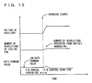
- a larger duty command value is applied for lower voltage of auxiliary battery 410. Furthermore, as shown in Fig. 3 , a difference between duty command values associated with different voltages of auxiliary battery 410 is larger as fan driving level F is higher.
- Cooling fan 402 is controlled through feedback employing a voltage converted from its number of revolutions. More specifically, revolution sensor 404 detects a number of revolutions of cooling fan 402, which is in turn converted by converter 406 into voltage. A signal representing the detected voltage is transmitted to hybrid ECU 600. Hybrid ECU 600 corrects a duty command value so that a voltage corresponding to a duty command value in the Fig. 2 map (i.e., a target voltage for cooling fan 402) and the voltage transmitted from converter 406 match.
- hybrid ECU 600 corrects the current duty command value to decrease. If converter 406 transmits a voltage lower than the target voltage, hybrid ECU 600 corrects the current duty command value to increase.
- hybrid ECU 600 sets fan driving level F for cooling fan 402 based on high voltage battery 400's temperature TB, SOC and input and output currents, and the cabin's internal temperature and background noise.
- hybrid ECU 600 detects the voltage of auxiliary battery 410 from a signal transmitted from voltage sensor 414.
- hybrid ECU 600 sets a duty command value for cooling fan 402, as based on fan driving level F and the voltage of auxiliary battery 410, with reference to the Fig. 2 map.
- hybrid ECU 600 transmits the set duty command value to cooling fan 402.
- hybrid ECU 600 operates cooling fan 402 at the set duty command value. Note that this duty command value may be corrected by feedback control.
- hybrid ECU 600 which is the control device of the present embodiment, will be described hereinafter.
- fan driving level F is set for cooling fan 402, as based on high voltage battery 400's temperature TB, SOC and input and output currents, and the cabin's internal temperature and background noise, to cool high voltage battery 400 (S100).
- cooling fan 402 Even if a single duty command value is applied to operate cooling fan 402, a number of revolution of cooling fan 402 may vary. It is because an electric power provided to cooling fan 402 varies if a voltage of auxiliary battery 410 varies. More specifically, if a single duty command value (or duty ratio) is applied to control cooling fan 402, and a voltage of auxiliary battery 410 is high, then cooling fan 402 may rotates at a higher rate and provide larger quantity of air than when a voltage of auxiliary battery 410 is low. In that case, the passenger(s) may be discomforted by the noise caused by cooling fan 402.
- a duty command value is corrected in accordance with the voltage of auxiliary battery 410 and to do so the voltage (output) from auxiliary battery 410 is detected from a signal transmitted from voltage sensor 414 (S102).
- a duty command value is set for cooling fan 402 with reference to the Fig. 2 map (S104), and applied to operate cooling fan 402 (S106).
- a hybrid ECU which is a control device of the present embodiment sets a duty command value in accordance with the voltage of an auxiliary battery serving as a power supply for a cooling fan. This can reduce variation of number of revolutions of the cooling fan which is caused by variation of a voltage of the auxiliary battery. Thus, a number of revolutions of the cooling fan can be thus be controlled precisely.
- the present embodiment differs from the first embodiment in that a duty command value for duty command values is set in accordance with an auxiliary battery's voltage.
- the remainder in structure is identical to that of the first embodiment. It is also identical in function. Accordingly, it will not be described repeatedly in detail.
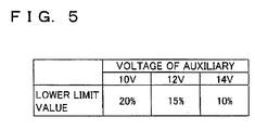
- hybrid ECU 600 sets a lower limit value for the duty command value with reference a map which has auxiliary battery 410's voltage as a parameter. According to this map, lower limit value for the duty command value is set to be lower as a voltage of auxiliary battery 410 is higher.
- hybrid ECU 600 detects the voltage of auxiliary battery 410 from a signal transmitted from voltage sensor 414.
- hybrid ECU 600 sets a lower limit value for the duty command value with reference to a map shown in Fig. 5 .
- hybrid ECU 600 determines whether a duty command value as corrected through feedback control based on a number of revolutions of cooling fan 402 is larger than the lower limit value. If duty command value as corrected through feedback control is larger than the lower limit value (YES at S204), the process proceeds to S206. Otherwise (NO at S204), the process proceeds to S208.
- hybrid ECU 600 transmits to cooling fan 402 the duty command value corrected through feedback control.
- hybrid ECU 600 operates cooling fan 402 at the duty command value corrected through feedback control.
- hybrid ECU 600 transmits the lower limit value for the duty command value to cooling fan 402. In other words, hybrid ECU 600 operates cooling fan 402 at the lower limit value for the duty command value.
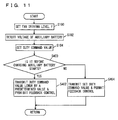
- hybrid ECU 600 which is the control device of the present embodiment will be described hereinafter.
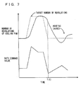
- the duty command value is significantly reduced, as shown in Fig. 7 , a number of revolutions of cooling fan 402 may decrease rapidly. Accordingly, the duty command value is corrected through feedback control to increase, and cooling fan 402 may have a hunting number of revolutions. This causes cooling fan 402 to generate a noise repeatedly increasing and decreasing as it operates, and the passenger(s) feel uncomfortable.
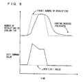
- a lower limit value is set for the duty command value, as based on the voltage of auxiliary battery 410 (S202). If a duty command value corrected through feedback control is larger than the lower limit value (YES at S204), cooling fan 402 is operated at the duty command value (corrected through feedback control) (S206).
- cooling fan 402 is operated at the lower limit value for the duty command value (S208). This, as shown in Fig. 8 , can prevent a number of revolutions of cooling fan 402 from reducing more than necessary and hunting.
- a hybrid ECU which is a control device of the present embodiment sets a lower limit value for a duty command value, as based on an auxiliary battery's voltage. This can prevent a number of revolutions of a cooling fan from reducing more than necessary, and hunting caused by feedback control based on the number of revolutions of the cooling fan.
- the present embodiment differs from the first and second embodiments in whether cooling fan 402 has a malfunction is determined from a duty command value corrected through feedback control based on the number of revolutions of cooling fan 402.
- the remainder in structure is identical to that of the first and second embodiments. It is also identical in function. Accordingly, it will not be described repeatedly in detail.
- hybrid ECU 600 calculates a deviation in absolute value between a duty command value set from fan driving level F and auxiliary battery 410's voltage with reference to the aforementioned Fig. 2 map and a duty command value as corrected through feedback control.
- hybrid ECU 600 determines whether the deviation in absolute value is larger than a threshold value. If the deviation in absolute value is larger than the threshold value (YES at S302), the process proceeds to S304. Otherwise (NO at S302), the process proceeds to S306.
- hybrid ECU 600 determines that cooling fan 402 has a malfunction.
- hybrid ECU 600 determines that cooling fan 402 is normal.
- hybrid ECU 600 which is the control device of the present embodiment will be described hereinafter.
- a deviation in absolute value is calculated between a duty command value set from fan driving level F and auxiliary battery 410's voltage and a duty command value corrected through feedback control (S300).
- cooling fan 402 is not operating with a number of revolutions corresponding to the duty command value set from fan driving level F and auxiliary battery 410's voltage. That is, it can be said that cooling fan 402 is not operating as controlled.
- cooling fan 402 has a malfunction is determined with reference to duty command value set as based on auxiliary battery 410's voltage. Thus whether cooling fan 402 has a malfunction can be determined considering a difference in number of revolutions of cooling fan 402 that is attributed to auxiliary battery 410's voltage. Whether cooling fan 402 has a malfunction can thus be determined with precision.
- hybrid ECU which is a control device of the present embodiment determines whether a cooling fan has a malfunction from a deviation in absolute value between a duty command value set from an auxiliary battery's voltage and a duty command value as corrected through feedback control.
- whether the cooling fan has a malfunction can be determined considering a difference in number of revolutions of the cooling fan that is attributed to the voltage of the auxiliary battery, which serves as a power supply for the cooling fan. Whether the cooling fan has a malfunction can thus be determined with precision.
- the present embodiment differs from the first to third embodiments in that (after the system is powered on) before charging auxiliary battery 410 starts, a duty command value is set to be low and correcting the duty command value through feedback control is prohibited.
- the remainder in structure is identical to that of the first to third embodiments. It is also identical in function. Accordingly, it will not be described repeatedly in detail.
- hybrid ECU 600 determines whether it is before charging auxiliary battery 410 starts (or charging the battery is interrupted). If it is before charging auxiliary battery 410 starts (YES at S400), the process proceeds to S402. Otherwise (NO at S400), the process proceeds to S404.
- hybrid ECU 600 transmits to cooling fan 402 a duty command value lower by a predetermined value than a duty command value set from fan driving level F and auxiliary battery 410's voltage with reference to the aforementioned Fig. 2 map, and also prohibits applying feedback control to that duty command value. Note that hybrid ECU 600 transmits to cooling fan 402 a duty command value corresponding to a voltage of auxiliary battery 410 that is attained after charging the battery has started.
- hybrid ECU 600 transmits to cooling fan 402 the duty command value set from fan driving level F and auxiliary battery 410's voltage, and also permits applying feedback control to the duty command value.
- hybrid ECU 600 which is the control device of the present embodiment will be described hereinafter.
- a voltage of auxiliary battery 410 rapidly increases.
- a number of revolutions of cooling fan 402 may rapidly increase.
- the duty command value is decreased by feedback control and a number of revolutions of cooling fan 402 decreases rapidly. If such a rapid variation in number of revolutions is repeated, a noise caused by operation of cooling fan 402 may vary rapidly and the passenger(s) may feel uncomfortable.
- a duty command value lower by a predetermined value than a duty command value set from fan driving level F and auxiliary battery 410's voltage is transmitted to cooling fan 402 (S402), and to maintain this duty command value (the duty command value set to be low), applying feedback control to the duty command value is prohibited (S402).
- a duty command value is set to be low previously before auxiliary battery 410 rapidly increases in voltage when charging the battery starts.
- a number of revolutions can be prevented from rapid increasing in the case that a voltage increases rapidly when charging auxiliary battery 410 starts.
- hybrid ECU which is a control device of the present embodiment operates a cooling fan at a duty command value lower than that set as based on the auxiliary battery's voltage before charging an auxiliary battery starts, and prohibits correcting the duty command value through feedback control.
- a duty command value is set to be low previously before voltage of the auxiliary battery rapidly increaseswhen charging the battery starts.
- a number of revolutions of the cooling fan can be prevented from increasing rapidly (or such rapidly increased number of revolutions can be minimized).
- a duty command value previously set to be low is set before charging auxiliary battery 410 starts, i.e., before a voltage of auxiliary battery 410 rapidly increases.
- a duty command value previously set to be low may be set when auxiliary battery 410 is readily to be charged (e.g., before a relay provided between high voltage battery 400 and auxiliary battery 410 turns on).
- a duty command value previously set to be high may be set before a voltage of auxiliary battery 410 rapidly decreases.
- a duty command value (or a duty ratio)
- a value in resistance between auxiliary battery 410 and cooling fan 402, or the like may be varied to control the number of revolutions of cooling fan 402.
- first to fourth embodiments have described examples applied to a series/parallel type hybrid system with power split device 102 dividing the motive force of engine 100 to an axle and MG (1) 200 to transmit it
- the present invention is also applicable to a series type hybrid vehicle that employs an engine only for driving a power generator and generates force driving an axle only by a motor that employs electric power generated by the power generator, and an electric vehicle traveling only by a motor.
Claims (18)
- Steuervorrichtung für einen Kühllüfter (402), welcher elektrische Energie von einer Hilfsbatterie als einem ersten Energiespeichermechanismus (410) empfängt, um angetrieben zu werden, Kühlluft zu blasen, um eine Hochspannungsbatterie für ein Fahrzeug als einem zweiten Energiespeichermechanismus (400) zu kühlen, welcher mit dem ersten Energiespeichermechanismus (410) verbunden ist, um den ersten Energiespeichermechanismus (410) mit elektrischer Energie über einen DC/DC-Wandler (412), welcher Spannung wandelt, zu versorgen, umfassend:einen Spannungssensor (414), der dazu ausgelegt ist, eine Spannung des ersten Energiespeichermechanismus (410) zu erfassen, undeine Betriebseinheit (600), die mit dem Spannungssensor (414) verbunden ist, wobei die Betriebseinheit (600) dazu ausgelegt ist, eine Anzahl von Umdrehungen des Kühllüfters (402) zu steuern und einen Steuerwert in Übereinstimmung mit der Spannung des ersten Energiespeichermechanismus (410) zum Varüeren der Anzahl von Umdrehungen des Kühllüfters (402) einzustellen.
- Steuervorrichtung für den Kühllüfter nach Anspruch 1, wobei zusätzlich dazu, dass sie ausgelegt ist, den Steuerwert in Übereinstimmung mit der Spannung des ersten Energiespeichermechanismus (410) einzustellen, die Betriebseinheit (600) dazu ausgelegt ist, den Steuerwert so einzustellen, dass eine Anzahl von Umdrehungen des Kühllüfters (402) größer ist, wenn der Ladezustand des zweiten Energiespeichermechanismus (400) größer ist.
- Steuervorrichtung für den Kühllüfter nach Anspruch 1, wobei zusätzlich dazu, dass sie ausgelegt ist, den Steuerwert in Übereinstimmung mit der Spannung des ersten Energiespeichermechanismus (410) einzustellen, die Betriebseinheit (600) dazu ausgelegt ist, den Steuerwert so einzustellen, dass eine Anzahl von Umdrehungen des Kühllüfters (402) größer ist, wenn ein Eingangs-/Ausgangs-Strom des zweiten Energiespeichermechanismus (400) größer ist.
- Steuervorrichtung für den Kühllüfter nach Anspruch 1, wobei zusätzlich dazu, dass sie ausgelegt ist, den Steuerwert in Übereinstimmung mit der Spannung des ersten Energiespeichermechanismus (410) einzustellen, die Betriebseinheit (600) dazu ausgelegt ist, den Steuerwert so einzustellen, dass eine Anzahl von Umdrehungen des Kühllüfters (402) größer ist, wenn ein Unterschied zwischen einer Temperatur des zweiten Energiespeichermechanismus (400) und einer Temperatur der von dem Kühllüfter (402) geblasenen Kühlluft kleiner ist.
- Steuervorrichtung für den Kühllüfter nach einem der Ansprüche 1 bis 4, wobei die Betriebseinheit (600) des Weiteren dazu ausgelegt ist, einen Grenzwert für den Steuerwert in Übereinstimmung mit der Spannung des ersten Energiespeichermechanismus (410) einzustellen.
- Steuervorrichtung für den Kühllüfter nach einem der Ansprüche 1 bis 5, wobei die Betriebseinheit (600) des Weiteren dazu ausgelegt ist, den Steuerwert durch Rückkoppelungsregelung auf der Grundlage des Betriebszustands des Kühllüfters (402) zu korrigieren, um den Kühllüfter (402) in einem vorbestimmten Betriebszustand zu betreiben, und wobei, wenn ein Unterschied zwischen dem Steuerwert, der durch die Rückkoppelungsregelung korrigiert wird, und dem Steuerwert, der in Übereinstimmung mit der Spannung des ersten Energiespeichermechanismus (410) eingestellt ist, größer ist als ein vorbestimmter Wert, die Betriebseinheit (600) dazu ausgelegt ist, festzustellen, dass der Kühllüfter (402) eine Betriebsstörung aufweist.
- Steuervorrichtung für den Kühllüfter nach einem der Ansprüche 1 bis 5, wobei:die Betriebseinheit (600) des Weiteren dazu ausgelegt ist, den Steuerwert durch Rückkoppelungsregelung auf der Grundlage des Betriebszustands des Kühllüfters (402) zu korrigieren, um den Kühllüfter (402) in einem vorbestimmten Betriebszustand zu betreiben,wenn eine vorbestimmte Bedingung in Bezug auf den ersten Energiespeichermechanismus (410) erfüllt ist, wobei die Betriebseinheit (600) dazu ausgelegt ist, das Korrigieren des Steuerwerts durch die Rückkoppelungsregelung zu unterdrücken, und,wenn die vorbestimmte Bedingung erfüllt ist, die Betriebseinheit (600) dazu ausgelegt ist, einen Steuerwert unterschiedlich zum Steuerwert, welcher in Übereinstimmung mit der Spannung des ersten Energiespeichermechanismus (410) eingestellt ist, einzustellen.
- Steuervorrichtung für den Kühllüfter nach Anspruch 7, wobei die vorbestimmte Bedingung eine Bedingung ist, welche eingestellt wurde, bevor das Laden des ersten Energiespeichermechanismus (410) beginnt.
- Steuervorrichtung für den Kühllüfter nach Anspruch 7 oder 8, wobei, wenn ein Unterschied zwischen dem Steuerwert, der durch die Rückkoppelungsregelung korrigiert wird, und dem Steuerwert, der in Übereinstimmung mit der Spannung des ersten Energiespeichermechanismus (410) eingestellt ist, größer ist als ein vorbestimmter Wert, die Betriebseinheit (600) dazu ausgelegt ist, festzustellen, dass der Kühllüfter (402) eine Betriebsstörung aufweist.
- Steuerverfahren für einen Kühllüfter (402), welcher Energie von einer Hilfsbatterie als einem ersten Energiespeichermechanismus (410) empfängt, um angetrieben zu werden, Kühlluft zu blasen, um eine Hochspannungsbatterie für ein Fahrzeug als einem zweiten Energiespeichermechanismus (400) zu kühlen, welcher mit dem ersten Energiespeichermechanismus (410) verbunden ist, um den ersten Energiespeichermechanismus (410) mit elektrischer Energie über einen DC/DC-Wandler (412), welcher Spannung wandelt, zu versorgen, umfassend die Schritte:Steuern einer Anzahl von Umdrehungen des Kühllüfters (402),Erfassen einer Spannung des ersten Energiespeichermechanismus (410) undEinstellen eines Steuerwerts in Übereinstimmung mit der Spannung des ersten Energiespeichermechanismus (410) zum Varüeren der Anzahl von Umdrehungen des Kühllüfters (402).
- Steuerverfahren für den Kühllüfter nach Anspruch 10, wobei zusätzlich zum Einstellen des Steuerwerts in Übereinstimmung mit der Spannung des ersten Energiespeichermechanismus (410) der Schritt des Einstellens des Steuerwerts den Schritt des derartigen Einstellens des Steuerwerts umfasst, so dass eine Anzahl von Umdrehungen des Kühllüfters (402) größer ist, wenn der Ladezustand des zweiten Energiespeichermechanismus (400) größer ist.
- Steuerverfahren für den Kühllüfter nach Anspruch 10, wobei zusätzlich zum Einstellen des Steuerwerts in Übereinstimmung mit der Spannung des ersten Energiespeichermechanismus (410) der Schritt des Einstellens des Steuerwerts den Schritt des derartigen Einstellens des Steuerwerts umfasst, so dass eine Anzahl von Umdrehungen des Kühllüfters (402) größer ist, wenn ein Eingangs-/Ausgangs-Strom des zweiten Energiespeichermechanismus (400) größer ist.
- Steuerverfahren für den Kühllüfter nach Anspruch 10, wobei zusätzlich zum Einstellen des Steuerwerts in Übereinstimmung mit der Spannung des ersten Energiespeichermechanismus (410) der Schritt des Einstellens des Steuerwerts den Schritt des derartigen Einstellens des Steuerwerts umfasst, so dass eine Anzahl von Umdrehungen des Kühllüfters (402) größer ist, wenn ein Unterschied zwischen einer Temperatur des zweiten Energiespeichermechanismus (400) und einer Temperatur der Kühlluft, welche von dem Kühllüfter (402) geblasen wird, kleiner ist.
- Steuerverfahren für den Kühllüfter nach einem der Ansprüche 10 bis 13, ferner umfassend den Schritt des Einstellens eines Grenzwerts für den Steuerwert in Übereinstimmung mit der Spannung des ersten Energiespeichermechanismus (410).
- Steuerverfahren für den Kühllüfter nach einem der Ansprüche 10 bis 14, des Weiteren umfassend die Schritte:Korrigieren des Steuerwerts durch Rückkoppelungsregelung auf der Grundlage des Betriebszustands des Kühllüfters (402), um den Kühllüfter (402) in einem vorbestimmten Betriebszustand zu betreiben, undBestimmen, dass der Kühllüfter (402) eine Betriebsstörung aufweist, wenn ein Unterschied zwischen dem Steuerwert, der durch die Rückkoppelungsregelung korrigiert wird, und dem Steuerwert, der in Übereinstimmung mit der Spannung des ersten Energiespeichermechanismus (410) eingestellt ist, größer ist als ein vorbestimmter Wert.
- Steuerverfahren für den Kühllüfter nach einem der Ansprüche 10 bis 14, ferner umfassend die Schritte:Korrigieren des Steuerwerts durch Rückkoppelungsregelung auf der Grundlage des Betriebszustands des Kühllüfters (402), um den Kühllüfter (402) in einem vorbestimmten Betriebszustand zu betreiben,Verhindern des Korrigierens des Steuerwerts durch die Rückkoppelungsregelung, wenn eine vorbestimmte Bedingung in Bezug auf den ersten Energiespeichermechanismus (410) erfüllt ist, undEinstellen eines Steuerwerts unterschiedlich zum Steuerwert in Übereinstimmung mit der Spannung des ersten Energiespeichermechanismus (410), wenn eine vorbestimmte Bedingung erfüllt ist.
- Steuerverfahren für den Kühllüfter nach Anspruch 16, wobei die vorbestimmte Bedingung eine Bedingung ist, welche eingestellt wird, bevor das Laden des ersten Energiespeichermechanismus (410) beginnt.
- Steuerverfahren für den Kühllüfter nach Anspruch 16 oder 17, des Weiteren umfassend den Schritt des Bestimmens, dass der Kühllüfter (402) eine Betriebsstörung aufweist, wenn ein Unterschied zwischen dem Steuerwert, welcher durch die Rückkoppelungsregelung korrigiert wird, und dem Steuerwert, welcher in Übereinstimmung mit der Spannung des ersten Energiespeichermechanismus (410) eingestellt ist, größer ist als ein voreingestellter Wert.
Applications Claiming Priority (2)
| Application Number | Priority Date | Filing Date | Title |
|---|---|---|---|
| JP2006019630A JP4848780B2 (ja) | 2006-01-27 | 2006-01-27 | 冷却ファンの制御装置 |
| PCT/JP2006/326182 WO2007086231A1 (ja) | 2006-01-27 | 2006-12-21 | 冷却ファンの制御装置および制御方法 |
Publications (3)
| Publication Number | Publication Date |
|---|---|
| EP1983603A1 EP1983603A1 (de) | 2008-10-22 |
| EP1983603A4 EP1983603A4 (de) | 2012-09-12 |
| EP1983603B1 true EP1983603B1 (de) | 2014-03-12 |
Family
ID=38309032
Family Applications (1)
| Application Number | Title | Priority Date | Filing Date |
|---|---|---|---|
| EP06843560.1A Expired - Fee Related EP1983603B1 (de) | 2006-01-27 | 2006-12-21 | Kühllüfter-steuereinrichtung und verfahren |
Country Status (6)
| Country | Link |
|---|---|
| US (1) | US8219248B2 (de) |
| EP (1) | EP1983603B1 (de) |
| JP (1) | JP4848780B2 (de) |
| KR (1) | KR101050487B1 (de) |
| CN (1) | CN101366144B (de) |
| WO (1) | WO2007086231A1 (de) |
Families Citing this family (47)
| Publication number | Priority date | Publication date | Assignee | Title |
|---|---|---|---|---|
| JP4466595B2 (ja) * | 2006-03-28 | 2010-05-26 | トヨタ自動車株式会社 | 冷却システムおよびこれを搭載する自動車並びに冷却システムの制御方法 |
| JP4327823B2 (ja) | 2006-06-15 | 2009-09-09 | トヨタ自動車株式会社 | 冷却システムおよびこれを搭載する自動車並びに冷却システムの制御方法 |
| US7793746B2 (en) * | 2007-03-09 | 2010-09-14 | Gm Global Technology Operations, Inc. | Noise-comfort function for cooling systems with proportional variable speed fans |
| US8465350B2 (en) * | 2007-06-28 | 2013-06-18 | GM Global Technology Operations LLC | Control method for RESS fan operation in a vehicle |
| FR2930077B1 (fr) * | 2008-04-10 | 2010-05-07 | Peugeot Citroen Automobiles Sa | Procede de commande d'un dispositif de thermoregulation d'une batterie d'alimentation d'un vehicule a traction electrique |
| FR2935646B1 (fr) * | 2008-09-11 | 2010-12-03 | Peugeot Citroen Automobiles Sa | Procede de commande d'un dispositif de thermoregulation d'une batterie d'alimentation d'un vehicule a traction electrique. |
| JP4947045B2 (ja) * | 2008-12-19 | 2012-06-06 | トヨタ自動車株式会社 | 冷却装置およびこれを搭載する車両 |
| DE102009031295A1 (de) * | 2009-06-30 | 2011-01-05 | Fev Motorentechnik Gmbh | Energiespeichervorrichtung |
| US20110048825A1 (en) * | 2009-08-28 | 2011-03-03 | Gary Starr | Air conditioner for electric car |
| JP2011055644A (ja) * | 2009-09-02 | 2011-03-17 | Toshiba Mitsubishi-Electric Industrial System Corp | 無停電電源装置 |
| JP5600979B2 (ja) * | 2010-03-19 | 2014-10-08 | パナソニック株式会社 | 炊飯器 |
| FR2963167B1 (fr) * | 2010-07-20 | 2013-03-08 | Peugeot Citroen Automobiles Sa | Dispositif et procede pour le refroidissement d'un moyen de stockage d'energie electrique |
| US20130063893A1 (en) * | 2010-09-06 | 2013-03-14 | Volvo Construction Equipment Ab | Energy repository discharge system for construction machinery |
| KR101297005B1 (ko) * | 2010-12-16 | 2013-08-14 | 삼성에스디아이 주식회사 | 배터리 온도 제어장치 및 방법 |
| US8651209B2 (en) * | 2010-12-20 | 2014-02-18 | Sony Corporation | Kinetic energy storage systems and methods of use |
| CN102544618B (zh) * | 2010-12-30 | 2014-08-13 | 上海航天电源技术有限责任公司 | 一种动力锂离子电池液冷温度控制管理方法 |
| EP2783898B1 (de) * | 2011-11-21 | 2018-05-02 | Toyota Jidosha Kabushiki Kaisha | Brennstoffzellensystem |
| DE102012201609A1 (de) * | 2012-02-03 | 2013-08-08 | Robert Bosch Gmbh | Regeleinrichtung für die Regelung eines Kühlkreislaufs zum Temperieren eines Batteriesystems mit mehr als einem Heiz- und/oder Kühlelement |
| DE102012016801B3 (de) * | 2012-08-23 | 2014-02-13 | Audi Ag | Kraftfahrzeug mit Batteriekühlung |
| KR101438901B1 (ko) | 2012-08-23 | 2014-09-16 | 현대자동차주식회사 | 고전압배터리 냉각블로워 제어장치 및 제어방법 |
| CN107878148B (zh) * | 2012-09-19 | 2021-02-12 | 日产自动车株式会社 | 冷暖空调装置 |
| JP6113455B2 (ja) * | 2012-10-12 | 2017-04-12 | 日野自動車株式会社 | 車載用電力制御装置の冷却システム及びその異常診断方法 |
| CN104042122B (zh) * | 2013-03-17 | 2016-02-17 | 李昆生 | 多烧烤腔的无烟电烧烤炉 |
| JP6191042B2 (ja) * | 2013-08-29 | 2017-09-06 | 三菱自動車工業株式会社 | 電動車両の充電システム |
| JP6187309B2 (ja) | 2014-02-21 | 2017-08-30 | トヨタ自動車株式会社 | 電動車両の電源装置 |
| JP6330219B2 (ja) * | 2014-03-17 | 2018-05-30 | 株式会社デンソー | モータ制御装置 |
| US10059222B2 (en) | 2014-04-15 | 2018-08-28 | Ford Global Technologies, Llc | Battery temperature estimation system |
| KR101575480B1 (ko) * | 2014-05-28 | 2015-12-07 | 현대자동차주식회사 | 저온 상태에서의 냉각팬 제어 방법 |
| JP6217618B2 (ja) | 2014-12-24 | 2017-10-25 | トヨタ自動車株式会社 | ハイブリッド車両の制御装置 |
| US9207732B1 (en) | 2015-02-25 | 2015-12-08 | Quanta Computer Inc. | Optimized fan duty control for computing device |
| JP6222159B2 (ja) | 2015-04-10 | 2017-11-01 | トヨタ自動車株式会社 | 車載二次電池の冷却システム |
| JP6269559B2 (ja) * | 2015-04-10 | 2018-01-31 | トヨタ自動車株式会社 | 車載二次電池の冷却システム |
| CN104863684B (zh) * | 2015-06-09 | 2017-12-08 | 宝沃汽车(中国)有限公司 | 车辆及其冷却风扇电机的监控方法和监控系统 |
| JP6491079B2 (ja) * | 2015-12-03 | 2019-03-27 | オートモーティブエナジーサプライ株式会社 | 電池パックの冷却ファン制御装置 |
| DE102016202807B4 (de) * | 2016-02-24 | 2022-12-22 | Audi Ag | Verfahren zum Aufladen eines Akkumulators eines elektrisch antreibbaren Kraftfahrzeugs |
| JP6790551B2 (ja) * | 2016-07-27 | 2020-11-25 | トヨタ自動車株式会社 | 電気自動車用の電源システム |
| WO2018189872A1 (ja) | 2017-04-13 | 2018-10-18 | 三菱電機株式会社 | 電力変換装置、電力変換装置の制御システム、電子機器及び冷却ファンの制御方法 |
| JP6787242B2 (ja) * | 2017-04-28 | 2020-11-18 | トヨタ自動車株式会社 | 電源システム |
| JP6496790B2 (ja) * | 2017-09-08 | 2019-04-03 | 株式会社Subaru | 車載機器冷却装置 |
| DE102018204992A1 (de) * | 2018-04-04 | 2019-10-10 | Bayerische Motoren Werke Aktiengesellschaft | Vorrichtung und Verfahren zum Steuern eines Ladevorgangs eines elektrischen Energiespeichers eines Kraftfahrzeugs sowie Ladesystem für einen elektrischen Energiespeicher |
| GB201819022D0 (en) * | 2018-11-22 | 2019-01-09 | Jaguar Land Rover Ltd | Vehicle controller and control method |
| KR20210050256A (ko) * | 2019-10-28 | 2021-05-07 | 주식회사 엘지화학 | 에너지저장시스템(ess)에 포함된 배터리 모듈의 냉각 시스템 및 그 방법 |
| CN112803036B (zh) * | 2019-11-14 | 2023-04-14 | 宇通客车股份有限公司 | 燃料电池热管理系统及其控制方法 |
| KR102287330B1 (ko) * | 2019-11-15 | 2021-08-06 | 삼성에스디아이 주식회사 | 팬 고장 검출 장치 |
| CN111987386B (zh) * | 2020-08-31 | 2021-11-12 | 东方醒狮(福建)储能科技有限公司 | 锂动力电池高温故障降温保护系统及其控制方法 |
| CN112026508B (zh) * | 2020-09-07 | 2021-07-02 | 东风小康汽车有限公司重庆分公司 | 增程式电动车冷却风扇控制方法 |
| CN112228367A (zh) * | 2020-09-27 | 2021-01-15 | 宝能(西安)汽车研究院有限公司 | 车用电池系统的冷却风扇的控制方法 |
Family Cites Families (28)
| Publication number | Priority date | Publication date | Assignee | Title |
|---|---|---|---|---|
| JPS61147708A (ja) * | 1984-12-19 | 1986-07-05 | Yamaha Motor Co Ltd | 電気自動車の駆動制御装置 |
| JPS6438521A (en) * | 1987-07-31 | 1989-02-08 | Noritz Corp | Safety device for combustor |
| JP2522974B2 (ja) * | 1987-11-20 | 1996-08-07 | 三洋電機株式会社 | 金型冷却装置 |
| JPH02168865A (ja) * | 1988-12-22 | 1990-06-28 | Hitachi Ltd | パルス変調装置、コンデンサ充電装置 |
| JP3220494B2 (ja) * | 1992-01-09 | 2001-10-22 | マツダ株式会社 | 車両用換気制御装置 |
| JP3733602B2 (ja) * | 1994-11-25 | 2006-01-11 | 日産自動車株式会社 | バッテリ冷却装置 |
| JPH11238530A (ja) * | 1998-02-23 | 1999-08-31 | Matsushita Electric Ind Co Ltd | モジュール電池の冷却方法および製造方法 |
| JP2001210389A (ja) | 2000-01-31 | 2001-08-03 | Sanyo Electric Co Ltd | 電池を備える電源装置 |
| JP2002051479A (ja) | 2000-07-31 | 2002-02-15 | Sanyo Electric Co Ltd | 電池の充電方法と充電装置 |
| JP2002151166A (ja) * | 2000-11-10 | 2002-05-24 | Japan Storage Battery Co Ltd | 二次電池の温度調整方法及び温度調整装置 |
| JP2003061400A (ja) * | 2001-08-20 | 2003-02-28 | Nissan Motor Co Ltd | 車両用発電機の制御装置 |
| JP2003111291A (ja) * | 2001-10-03 | 2003-04-11 | Matsushita Electric Ind Co Ltd | 燃料電池発電システムに用いる二次電池の充電制御方法 |
| US20030107341A1 (en) * | 2001-12-11 | 2003-06-12 | Georgia-Pacific Corporation | Motor control usable with high ripple BEMF feedback signal to achieve precision burst mode motor operation |
| JP4053289B2 (ja) * | 2001-12-12 | 2008-02-27 | 本田技研工業株式会社 | 蓄電池の温度制御装置、及びそれを用いた車両装置 |
| JP3761822B2 (ja) * | 2002-03-15 | 2006-03-29 | 日本電信電話株式会社 | 電源装置 |
| JP3843956B2 (ja) * | 2002-05-14 | 2006-11-08 | トヨタ自動車株式会社 | 車載バッテリのファン制御方法およびファン制御装置 |
| JP2004080914A (ja) * | 2002-08-19 | 2004-03-11 | Sanyo Electric Co Ltd | 電気自動車 |
| TWI230493B (en) * | 2002-10-11 | 2005-04-01 | Hitachi Koki Kk | Charging apparatus |
| JP2005063689A (ja) * | 2003-08-12 | 2005-03-10 | Nissan Motor Co Ltd | バッテリ冷却制御装置 |
| JP2005184979A (ja) | 2003-12-19 | 2005-07-07 | Sanyo Electric Co Ltd | 車両用の電源装置およびハイブリッドカーの電源装置 |
| US7479753B1 (en) * | 2004-02-24 | 2009-01-20 | Nvidia Corporation | Fan speed controller |
| JP2005333738A (ja) * | 2004-05-20 | 2005-12-02 | Toyota Motor Corp | 冷却装置制御装置、冷却装置異常検出装置、冷却装置異常検出方法および冷却装置の異常検出をコンピュータに実行させるためのプログラムを記録したコンピュータ読取り可能な記録媒体 |
| JP4792712B2 (ja) * | 2004-06-02 | 2011-10-12 | トヨタ自動車株式会社 | 電源の冷却装置 |
| KR20060024917A (ko) * | 2004-09-15 | 2006-03-20 | 현대모비스 주식회사 | 차량의 액추에이터 전원보정장치 및 보정방법 |
| US7441616B2 (en) * | 2004-12-27 | 2008-10-28 | Nissan Motor Co., Ltd. | Generated power control system |
| JP4791054B2 (ja) * | 2005-03-02 | 2011-10-12 | プライムアースEvエナジー株式会社 | 温度管理装置及び電源装置 |
| JP5091579B2 (ja) * | 2007-07-26 | 2012-12-05 | 矢崎総業株式会社 | 負荷制御装置 |
| JP4947045B2 (ja) * | 2008-12-19 | 2012-06-06 | トヨタ自動車株式会社 | 冷却装置およびこれを搭載する車両 |
-
2006
- 2006-01-27 JP JP2006019630A patent/JP4848780B2/ja active Active
- 2006-12-21 KR KR1020087020832A patent/KR101050487B1/ko active IP Right Grant
- 2006-12-21 US US12/087,785 patent/US8219248B2/en active Active
- 2006-12-21 WO PCT/JP2006/326182 patent/WO2007086231A1/ja active Application Filing
- 2006-12-21 CN CN2006800517219A patent/CN101366144B/zh not_active Expired - Fee Related
- 2006-12-21 EP EP06843560.1A patent/EP1983603B1/de not_active Expired - Fee Related
Also Published As
| Publication number | Publication date |
|---|---|
| JP2007200780A (ja) | 2007-08-09 |
| US20090024252A1 (en) | 2009-01-22 |
| CN101366144A (zh) | 2009-02-11 |
| CN101366144B (zh) | 2012-07-25 |
| EP1983603A1 (de) | 2008-10-22 |
| EP1983603A4 (de) | 2012-09-12 |
| KR101050487B1 (ko) | 2011-07-20 |
| US8219248B2 (en) | 2012-07-10 |
| WO2007086231A1 (ja) | 2007-08-02 |
| JP4848780B2 (ja) | 2011-12-28 |
| KR20080091495A (ko) | 2008-10-13 |
Similar Documents
| Publication | Publication Date | Title |
|---|---|---|
| EP1983603B1 (de) | Kühllüfter-steuereinrichtung und verfahren | |
| US10381695B2 (en) | Cooling system for secondary battery | |
| US6075346A (en) | Secondary battery charge and discharge control device | |
| US9018894B2 (en) | Vehicular power supply system | |
| US9475486B2 (en) | Controller for hybrid vehicle | |
| US7267191B2 (en) | System and method for battery protection strategy for hybrid electric vehicles | |
| US8930098B2 (en) | Clutch control device of hybrid vehicle | |
| US6630810B2 (en) | Hybrid vehicle and control method therefor | |
| US8418789B2 (en) | Cooling system, vehicle equipped with the cooling system, and method for controlling the cooling system | |
| US8096919B2 (en) | Motor control device, motored vehicle equipped therewith, and method of controlling a motor | |
| EP2173018A1 (de) | Stromquellenvorrichtung für ein fahrzeug | |
| KR101807364B1 (ko) | 전동 모터에 의하여 구동되는 차량 및 그 차량의 제어 방법 | |
| JP2008271781A (ja) | 二次電池の充放電制御装置 | |
| EP2908426A1 (de) | Stromerzeugungssteuerungsvorrichtung | |
| KR101558359B1 (ko) | 하이브리드 차량의 토크 모니터링 방법 | |
| JP2010161904A (ja) | 冷却ファンの駆動制御装置 | |
| JP2008189236A (ja) | ハイブリッド車両の制御装置 | |
| US7084589B1 (en) | Vehicle and method for controlling power to wheels in a vehicle | |
| JP2007295785A (ja) | コンバータの制御装置 | |
| US11958468B2 (en) | Method for operating a motor vehicle and the corresponding motor vehicle | |
| JP2006304392A (ja) | ハイブリッド車およびその制御方法 | |
| JP2005218283A (ja) | 車両に搭載された電力変換機構の冷却装置 | |
| JP2006174555A (ja) | 動力出力装置およびこれを搭載する自動車並びに動力出力装置の制御方法 |
Legal Events
| Date | Code | Title | Description |
|---|---|---|---|
| PUAI | Public reference made under article 153(3) epc to a published international application that has entered the european phase |
Free format text: ORIGINAL CODE: 0009012 |
|
| 17P | Request for examination filed |
Effective date: 20080827 |
|
| AK | Designated contracting states |
Kind code of ref document: A1 Designated state(s): DE FR |
|
| DAX | Request for extension of the european patent (deleted) | ||
| RBV | Designated contracting states (corrected) |
Designated state(s): DE FR |
|
| A4 | Supplementary search report drawn up and despatched |
Effective date: 20120810 |
|
| RIC1 | Information provided on ipc code assigned before grant |
Ipc: H01M 10/50 20060101AFI20120806BHEP |
|
| 17Q | First examination report despatched |
Effective date: 20121031 |
|
| RAP1 | Party data changed (applicant data changed or rights of an application transferred) |
Owner name: TOYOTA JIDOSHA KABUSHIKI KAISHA |
|
| RIC1 | Information provided on ipc code assigned before grant |
Ipc: H01M 8/04 20060101ALN20130808BHEP Ipc: B60K 1/00 20060101ALN20130808BHEP Ipc: B60K 6/445 20071001ALI20130808BHEP Ipc: B60W 20/00 20060101ALI20130808BHEP Ipc: B60L 11/18 20060101ALI20130808BHEP Ipc: H01M 10/50 20060101AFI20130808BHEP Ipc: B60W 10/30 20060101ALI20130808BHEP |
|
| GRAP | Despatch of communication of intention to grant a patent |
Free format text: ORIGINAL CODE: EPIDOSNIGR1 |
|
| INTG | Intention to grant announced |
Effective date: 20131004 |
|
| GRAS | Grant fee paid |
Free format text: ORIGINAL CODE: EPIDOSNIGR3 |
|
| REG | Reference to a national code |
Ref country code: DE Ref legal event code: R079 Ref document number: 602006040692 Country of ref document: DE Free format text: PREVIOUS MAIN CLASS: H01M0010500000 Ipc: H01M0010600000 |
|
| GRAA | (expected) grant |
Free format text: ORIGINAL CODE: 0009210 |
|
| AK | Designated contracting states |
Kind code of ref document: B1 Designated state(s): DE FR |
|
| RIC1 | Information provided on ipc code assigned before grant |
Ipc: B60K 1/00 20060101ALN20140205BHEP Ipc: B60W 10/30 20060101ALI20140205BHEP Ipc: B60L 11/18 20060101ALI20140205BHEP Ipc: H01M 10/60 20140101AFI20140205BHEP Ipc: B60K 6/445 20071001ALI20140205BHEP Ipc: H01M 8/04 20060101ALN20140205BHEP Ipc: B60W 20/00 20060101ALI20140205BHEP |
|
| REG | Reference to a national code |
Ref country code: DE Ref legal event code: R096 Ref document number: 602006040692 Country of ref document: DE Effective date: 20140424 |
|
| REG | Reference to a national code |
Ref country code: DE Ref legal event code: R084 Ref document number: 602006040692 Country of ref document: DE |
|
| REG | Reference to a national code |
Ref country code: DE Ref legal event code: R084 Ref document number: 602006040692 Country of ref document: DE Effective date: 20140929 |
|
| REG | Reference to a national code |
Ref country code: DE Ref legal event code: R097 Ref document number: 602006040692 Country of ref document: DE |
|
| PLBE | No opposition filed within time limit |
Free format text: ORIGINAL CODE: 0009261 |
|
| STAA | Information on the status of an ep patent application or granted ep patent |
Free format text: STATUS: NO OPPOSITION FILED WITHIN TIME LIMIT |
|
| 26N | No opposition filed |
Effective date: 20141215 |
|
| REG | Reference to a national code |
Ref country code: DE Ref legal event code: R097 Ref document number: 602006040692 Country of ref document: DE Effective date: 20141215 |
|
| REG | Reference to a national code |
Ref country code: FR Ref legal event code: ST Effective date: 20150831 |
|
| PG25 | Lapsed in a contracting state [announced via postgrant information from national office to epo] |
Ref country code: FR Free format text: LAPSE BECAUSE OF NON-PAYMENT OF DUE FEES Effective date: 20141231 |
|
| PGFP | Annual fee paid to national office [announced via postgrant information from national office to epo] |
Ref country code: DE Payment date: 20211102 Year of fee payment: 16 |
|
| REG | Reference to a national code |
Ref country code: DE Ref legal event code: R119 Ref document number: 602006040692 Country of ref document: DE |
|
| PG25 | Lapsed in a contracting state [announced via postgrant information from national office to epo] |
Ref country code: DE Free format text: LAPSE BECAUSE OF NON-PAYMENT OF DUE FEES Effective date: 20230701 |