EP1983204B1 - Détecteur de deterioration de lubrifiant et ensemble de palier avec ledit détecteur - Google Patents
Détecteur de deterioration de lubrifiant et ensemble de palier avec ledit détecteur Download PDFInfo
- Publication number
- EP1983204B1 EP1983204B1 EP07706283A EP07706283A EP1983204B1 EP 1983204 B1 EP1983204 B1 EP 1983204B1 EP 07706283 A EP07706283 A EP 07706283A EP 07706283 A EP07706283 A EP 07706283A EP 1983204 B1 EP1983204 B1 EP 1983204B1
- Authority
- EP
- European Patent Office
- Prior art keywords
- light
- lubricant
- detecting device
- light detecting
- deterioration
- Prior art date
- Legal status (The legal status is an assumption and is not a legal conclusion. Google has not performed a legal analysis and makes no representation as to the accuracy of the status listed.)
- Expired - Fee Related
Links
- 239000000314 lubricant Substances 0.000 title claims description 372
- 230000006866 deterioration Effects 0.000 title claims description 208
- 239000013307 optical fiber Substances 0.000 claims description 81
- 238000001514 detection method Methods 0.000 claims description 69
- 238000002834 transmittance Methods 0.000 claims description 43
- 239000000126 substance Substances 0.000 claims description 39
- 229920006395 saturated elastomer Polymers 0.000 claims description 10
- 238000010276 construction Methods 0.000 description 43
- 238000010586 diagram Methods 0.000 description 32
- 230000002411 adverse Effects 0.000 description 27
- 238000009434 installation Methods 0.000 description 11
- 238000005259 measurement Methods 0.000 description 9
- 230000001419 dependent effect Effects 0.000 description 8
- 230000002238 attenuated effect Effects 0.000 description 6
- 230000003287 optical effect Effects 0.000 description 6
- 230000005856 abnormality Effects 0.000 description 5
- 239000004065 semiconductor Substances 0.000 description 5
- 239000011521 glass Substances 0.000 description 4
- 238000005461 lubrication Methods 0.000 description 4
- 239000000463 material Substances 0.000 description 4
- 238000012544 monitoring process Methods 0.000 description 4
- 230000002093 peripheral effect Effects 0.000 description 4
- 229920003002 synthetic resin Polymers 0.000 description 4
- 239000000057 synthetic resin Substances 0.000 description 4
- 239000012780 transparent material Substances 0.000 description 4
- 238000005096 rolling process Methods 0.000 description 3
- XLYOFNOQVPJJNP-UHFFFAOYSA-N water Substances O XLYOFNOQVPJJNP-UHFFFAOYSA-N 0.000 description 3
- 238000012935 Averaging Methods 0.000 description 2
- 238000012937 correction Methods 0.000 description 2
- 230000002950 deficient Effects 0.000 description 2
- 238000006073 displacement reaction Methods 0.000 description 2
- 230000000694 effects Effects 0.000 description 2
- 239000000835 fiber Substances 0.000 description 2
- 238000000034 method Methods 0.000 description 2
- 238000007254 oxidation reaction Methods 0.000 description 2
- 238000010521 absorption reaction Methods 0.000 description 1
- 230000003321 amplification Effects 0.000 description 1
- 230000005540 biological transmission Effects 0.000 description 1
- 238000006243 chemical reaction Methods 0.000 description 1
- 239000000428 dust Substances 0.000 description 1
- 238000005516 engineering process Methods 0.000 description 1
- 239000004519 grease Substances 0.000 description 1
- 238000003780 insertion Methods 0.000 description 1
- 230000037431 insertion Effects 0.000 description 1
- 230000031700 light absorption Effects 0.000 description 1
- 238000012423 maintenance Methods 0.000 description 1
- 238000003199 nucleic acid amplification method Methods 0.000 description 1
- 230000003647 oxidation Effects 0.000 description 1
- 238000007789 sealing Methods 0.000 description 1
Images


Classifications
-
- G—PHYSICS
- G01—MEASURING; TESTING
- G01N—INVESTIGATING OR ANALYSING MATERIALS BY DETERMINING THEIR CHEMICAL OR PHYSICAL PROPERTIES
- G01N33/00—Investigating or analysing materials by specific methods not covered by groups G01N1/00 - G01N31/00
- G01N33/26—Oils; viscous liquids; paints; inks
- G01N33/28—Oils, i.e. hydrocarbon liquids
- G01N33/2888—Lubricating oil characteristics, e.g. deterioration
-
- F—MECHANICAL ENGINEERING; LIGHTING; HEATING; WEAPONS; BLASTING
- F16—ENGINEERING ELEMENTS AND UNITS; GENERAL MEASURES FOR PRODUCING AND MAINTAINING EFFECTIVE FUNCTIONING OF MACHINES OR INSTALLATIONS; THERMAL INSULATION IN GENERAL
- F16C—SHAFTS; FLEXIBLE SHAFTS; ELEMENTS OR CRANKSHAFT MECHANISMS; ROTARY BODIES OTHER THAN GEARING ELEMENTS; BEARINGS
- F16C19/00—Bearings with rolling contact, for exclusively rotary movement
- F16C19/22—Bearings with rolling contact, for exclusively rotary movement with bearing rollers essentially of the same size in one or more circular rows, e.g. needle bearings
- F16C19/34—Bearings with rolling contact, for exclusively rotary movement with bearing rollers essentially of the same size in one or more circular rows, e.g. needle bearings for both radial and axial load
- F16C19/38—Bearings with rolling contact, for exclusively rotary movement with bearing rollers essentially of the same size in one or more circular rows, e.g. needle bearings for both radial and axial load with two or more rows of rollers
- F16C19/383—Bearings with rolling contact, for exclusively rotary movement with bearing rollers essentially of the same size in one or more circular rows, e.g. needle bearings for both radial and axial load with two or more rows of rollers with tapered rollers, i.e. rollers having essentially the shape of a truncated cone
- F16C19/385—Bearings with rolling contact, for exclusively rotary movement with bearing rollers essentially of the same size in one or more circular rows, e.g. needle bearings for both radial and axial load with two or more rows of rollers with tapered rollers, i.e. rollers having essentially the shape of a truncated cone with two rows, i.e. double-row tapered roller bearings
- F16C19/386—Bearings with rolling contact, for exclusively rotary movement with bearing rollers essentially of the same size in one or more circular rows, e.g. needle bearings for both radial and axial load with two or more rows of rollers with tapered rollers, i.e. rollers having essentially the shape of a truncated cone with two rows, i.e. double-row tapered roller bearings in O-arrangement
-
- F—MECHANICAL ENGINEERING; LIGHTING; HEATING; WEAPONS; BLASTING
- F16—ENGINEERING ELEMENTS AND UNITS; GENERAL MEASURES FOR PRODUCING AND MAINTAINING EFFECTIVE FUNCTIONING OF MACHINES OR INSTALLATIONS; THERMAL INSULATION IN GENERAL
- F16C—SHAFTS; FLEXIBLE SHAFTS; ELEMENTS OR CRANKSHAFT MECHANISMS; ROTARY BODIES OTHER THAN GEARING ELEMENTS; BEARINGS
- F16C33/00—Parts of bearings; Special methods for making bearings or parts thereof
- F16C33/30—Parts of ball or roller bearings
- F16C33/66—Special parts or details in view of lubrication
- F16C33/6637—Special parts or details in view of lubrication with liquid lubricant
- F16C33/6659—Details of supply of the liquid to the bearing, e.g. passages or nozzles
- F16C33/667—Details of supply of the liquid to the bearing, e.g. passages or nozzles related to conditioning, e.g. cooling, filtering
-
- F—MECHANICAL ENGINEERING; LIGHTING; HEATING; WEAPONS; BLASTING
- F16—ENGINEERING ELEMENTS AND UNITS; GENERAL MEASURES FOR PRODUCING AND MAINTAINING EFFECTIVE FUNCTIONING OF MACHINES OR INSTALLATIONS; THERMAL INSULATION IN GENERAL
- F16C—SHAFTS; FLEXIBLE SHAFTS; ELEMENTS OR CRANKSHAFT MECHANISMS; ROTARY BODIES OTHER THAN GEARING ELEMENTS; BEARINGS
- F16C33/00—Parts of bearings; Special methods for making bearings or parts thereof
- F16C33/30—Parts of ball or roller bearings
- F16C33/66—Special parts or details in view of lubrication
- F16C33/6637—Special parts or details in view of lubrication with liquid lubricant
- F16C33/6659—Details of supply of the liquid to the bearing, e.g. passages or nozzles
- F16C33/6674—Details of supply of the liquid to the bearing, e.g. passages or nozzles related to the amount supplied, e.g. gaps to restrict flow of the liquid
-
- F—MECHANICAL ENGINEERING; LIGHTING; HEATING; WEAPONS; BLASTING
- F16—ENGINEERING ELEMENTS AND UNITS; GENERAL MEASURES FOR PRODUCING AND MAINTAINING EFFECTIVE FUNCTIONING OF MACHINES OR INSTALLATIONS; THERMAL INSULATION IN GENERAL
- F16N—LUBRICATING
- F16N29/00—Special means in lubricating arrangements or systems providing for the indication or detection of undesired conditions; Use of devices responsive to conditions in lubricating arrangements or systems
-
- G—PHYSICS
- G01—MEASURING; TESTING
- G01N—INVESTIGATING OR ANALYSING MATERIALS BY DETERMINING THEIR CHEMICAL OR PHYSICAL PROPERTIES
- G01N21/00—Investigating or analysing materials by the use of optical means, i.e. using sub-millimetre waves, infrared, visible or ultraviolet light
- G01N21/17—Systems in which incident light is modified in accordance with the properties of the material investigated
- G01N21/47—Scattering, i.e. diffuse reflection
- G01N21/49—Scattering, i.e. diffuse reflection within a body or fluid
- G01N21/53—Scattering, i.e. diffuse reflection within a body or fluid within a flowing fluid, e.g. smoke
- G01N21/534—Scattering, i.e. diffuse reflection within a body or fluid within a flowing fluid, e.g. smoke by measuring transmission alone, i.e. determining opacity
-
- G—PHYSICS
- G01—MEASURING; TESTING
- G01N—INVESTIGATING OR ANALYSING MATERIALS BY DETERMINING THEIR CHEMICAL OR PHYSICAL PROPERTIES
- G01N21/00—Investigating or analysing materials by the use of optical means, i.e. using sub-millimetre waves, infrared, visible or ultraviolet light
- G01N21/17—Systems in which incident light is modified in accordance with the properties of the material investigated
- G01N21/59—Transmissivity
-
- F—MECHANICAL ENGINEERING; LIGHTING; HEATING; WEAPONS; BLASTING
- F16—ENGINEERING ELEMENTS AND UNITS; GENERAL MEASURES FOR PRODUCING AND MAINTAINING EFFECTIVE FUNCTIONING OF MACHINES OR INSTALLATIONS; THERMAL INSULATION IN GENERAL
- F16N—LUBRICATING
- F16N2200/00—Condition of lubricant
Definitions
- the present invention relates to a lubricant deterioration detecting device for detecting the status of deterioration of a lubricant resulting from admixture of an alien substance and also to a detecting device incorporated bearing assembly equipped with such lubricant detection detecting device such as, for example, a detector incorporated bearing assembly for use in railway vehicles, automotive vehicles and industrial machines or the like.
- an insufficient lubrication occurs once the lubricant (such as, for example, a grease or oil) within the bearing assembly is deteriorated, resulting in a reduction in lifetime of the bearing assembly. Since determination of the occurrence of the insufficient lubrication in reference to the status of vibration or the like occurring in the bearing assembly is carried out when and after an operating abnormality has occurred as a result of expiration of the lifetime of the bearing assembly, the presence or absence of an abnormality in lubrication cannot be carried out at an early time. In view of this, it has been desired to monitor the status of the lubricant within the bearing assembly regularly or in real time so that the occurrence of the abnormality and/or the time for maintenance can be predicated.
- the lubricant such as, for example, a grease or oil
- a major cause of deterioration of the lubricant may include an admixture of powdery wear debris, which is produced as the bearing assembly is used, into the lubricant.
- a sensor incorporated bearing assembly for detecting the status of wear of the bearing assembly, in which a sensor in the form of an electrode or a coil is arranged inside a sealing member of the bearing assembly so that the electrical characteristic of the lubricant resulting from the admixture of the wear debris can be detected.
- a sensor in the form of an electrode or a coil is arranged inside a sealing member of the bearing assembly so that the electrical characteristic of the lubricant resulting from the admixture of the wear debris can be detected.
- rays of light emitted from the light emitting element 53 are transmitted across the lubricant 55, positioned at a measuring site 58, through the light emitting optical fiber 56 and are subsequently detected by the light receiving element 54 through the light receiving optical fiber 57, whereby the amount of foreign matter admixed in the lubricant 55 can be estimated from the intensity of the transmitted light detected by the light receiving element 54.
- the surface area of each of the optical fibers 56 and 57 at the measuring site 58 can be minimized, ingress of the lubricant 55 into the measuring site 58 can be facilitated and the lubricant once entering the measuring site 58 can easily be maintained at a constant thickness.
- the measuring site 58 requires a vessel of a structure designed to maintain the thickness d of the lubricant 55 at a constant value and, therefore, the freedom of arrangement within, for example, a bearing assembly is lowered particularly where it is used in detecting the status of deterioration of the lubricant of a kind sealed within the bearing assembly.
- US 2005/088646 A1 discloses an apparatus for measuring oil oxidation which comprises a first light-reflecting mirror 30, window 28, a second light-reflecting mirror 32, ultraviolet light-emitting means 22, a pair of first light-transmitting means (fibers) 24 which are connected to said light-emitting means 22, and first and second light-transmitting means (fibers) 26 connected to first and second light-receiving means 34, 36.
- the reflecting means are located in oil 50 in oil tank 52 and the light is provided to and from the oil via first and second optical window 28, 29.
- the output P1 from first light-receiving means 34 having a light-passing distance of "2d1"and the output P2 from second light-receiving means 36 having a light-passing distance of "2d2" are expressed in an equation which determines the absorption based only on the difference "d2-d1".
- a control portion determines the status of the oil on the basis of the measured light absorption coefficient by using pre-stored reference values.
- An object of the present invention is to provide a lubricant deterioration detecting device having a high degree of freedom in arranging within the bearing assembly or the like and capable of stably detecting the status of deterioration of the lubricant without being affected by the thickness of the lubricant and a change in temperature and also to provide a detecting device incorporated bearing assembly equipped with such lubricant deterioration detecting device.
- the lubricant deterioration detecting device of the present invention is defined according the appended claims.
- this lubricant deterioration detecting device is so designed that while the plural light detecting components are arranged, for example, in line with their light detecting faces sequentially displaced in position, the status of deterioration of the lubricant can be detected when the signal strengths of the outputs of those light detecting components are compared with each other by the determining unit, the status of deterioration of the lubricant can be detected without being affected by the thickness of the lubricant itself, the intensity of light emitted from the light source and the distance between the light source and the light detecting components, when such detection is made with the plural light detecting components arranged in the lubricant.
- the lubricant deterioration detecting device is arranged within the bearing assembly, a large freedom of arrangement is available and construction is possible to accommodate to the limited available space for installation.
- a stable detection can be accomplished without being adversely affected by common mode noises such as a power source variation.
- arrangement of the light detecting components within the lubricant is effective in that influences brought about by a temperature dependent change in characteristic can be counterbalanced among the plural light detecting components and, accordingly, a highly accurate detection can be accomplished.
- the determining unit referred to above may be of a type capable of estimating an amount of the alien substance admixed into the lubricant through comparison of the signal strengths referred to above.
- the determining unit can detect the status of lubricant from the estimated amount of the alien substance admixed.
- each of the light detecting components referred to above includes a detector and a light guide element having one end in the form of a base end connected with the detector and the other end in the form of a free end forming the light detecting face. Since even in this construction, the plural light detecting components have their detecting faces sequentially displaced in position, the status of deterioration of the lubricant can be detected without being affected by the thickness of the lubricant itself, the intensity of the light source and the distance between the light source and the light detecting components.
- each of the light detecting components referred to above may include a detector and an optical fiber having one end in the form of a base end connected with the detector and the other end in the form of a free end forming the light detecting face.
- a detecting site where the plural light detecting components are arranged, can have a reduced thickness and, therefore, the lubricant can be allowed to enter the detecting site easily and a stable detection can be accomplished accordingly.
- the light source may be in the form of a linear-shaped light source. Where the light source is in a line shape, the intensity of light incident on the detecting site comes to be uniform regardless of the position and, therefore, a stable detection is possible.
- the determining unit referred to above may be of a type capable of calculating a light transmittance of the lubricant. Since the light transmittance of the lubricant attenuates as the deterioration of the lubricant proceeds accompanied by, for example, an increase of the amount of the alien substance admixed within the lubricant, calculation of the light transmittance of the lubricant can lead to detection of the status of deterioration of the lubricant.
- the determining unit includes a selector section for excluding, from the output signals of the plural light detecting components, output signals of a light detecting components which generate a saturated output, and output signals of light detecting components indicative of a detected light intensity not attaining a predetermined value, in order to use respective output signals of the rest of the light detecting components for detection of the status of deterioration of the lubricant.
- the lubricant deterioration detecting device of the present invention may include two light detecting components of the kind referred to above.
- the lubricant deterioration detecting device of the construction described above According to the lubricant deterioration detecting device of the construction described above, rays of light from the light source are attenuated before they reach the light detecting components as they are absorbed and/or scattered on the way, and the intensity of such light is detected by the first light detecting components.
- the output of the second light detecting component to which light arrives first the output of the second light detecting component is evaluated, it is possible to detect the amount of light attenuated due to the distance between the two light detecting components.
- the degree of freedom of arrangement comes to be high and construction is possible to accommodate to the limited space available for installation. Also, because of the construction in which the signal strengths of the two light detecting components are compared to achieve the detection, a stable detection can be accomplished without adversely affected by common mode noises such as variation in electric power supply. Even though the two light detecting components are arranged within the lubricant, changes in characteristic resulting from change in temperature between the two light detecting components can be counterbalanced and, hence, an accurate detection can be accomplished.
- a temperature sensor may be provided at a position in proximity to the light detecting components.
- the temperature sensor by allowing the temperature sensor to monitor the temperatures of the lubricant and the light detecting components, correction appropriate to the temperature dependent change can be applied to the detection result. Accordingly, a further accurate detection can be accomplished and the possibility that a change in detected signal resulting from a change in ambient temperature would be erroneously determined as resulting from the deterioration of the lubricant can be avoided.
- a light amount adjusting unit may be provided for adjusting an amount of light of the light source so that an output of one of the two light detecting components, which is closest the light source, attains a predetermined constant value.
- the light amount adjusting unit automatically adjusts the amount of light of the light source so that the output of the light detecting component can attain a predetermined constant value and, accordingly, a stabilized detection can be accomplished. Accordingly, when the difference between the respective outputs of the two light detecting components is used, estimation of the status of deterioration of the lubricant, for example, estimation of the amount of the alien substance, generated as a result of, for example, frictional wear, which is admixed can be accomplished.
- the degree of freedom of arrangement comes to be high and construction is possible to accommodate to the limited space limited space available for installation. Also, because of the construction in which the signal strengths of the two light detecting components are compared to achieve the detection, a stable detection can be accomplished without adversely affected by common mode noises such as variation in electric power supply. Even though the two light detecting components are arranged within the lubricant, changes in characteristic resulting from change in temperature between the two light detecting components can be counterbalanced and, hence, an accurate detection can be accomplished.
- a light amount adjusting unit may be provided for adjusting an amount of light of the light source so that an output of one of the two light detecting components, which is remotest from the light source, attains a predetermined constant value.
- an amplifying unit for amplifying an output of each of the light detecting components and a unit for adjusting a gain of the amplifying unit may be provided, in which case the determining unit compares the outputs amplified by the amplifying unit to detect the status of deterioration of the lubricant and wherein the gain adjusting unit adjusts a gain of the amplifying unit to allow the output of each of the light detecting components, which has been amplified by the amplifying unit, to attain a value within a predetermined range.
- the gain adjusting unit adjusts the gain of the amplifying unit and, accordingly, a stable measurement can be accomplished. Accordingly, when the difference between the respective outputs of the two light detecting components is used, estimation of the status of deterioration of the lubricant, for example, estimation of the amount of the alien substance, generated as a result of, for example, frictional wear, which is admixed can be accomplished.
- the degree of freedom of arrangement comes to be high and construction is possible to accommodate to the limited space available for installation. Also, because of the construction in which the signal strengths of the two light detecting components are compared to achieve the detection, a stable detection can be accomplished without adversely affected by common mode noises such as variation in electric power supply. Even though the two light detecting components are arranged within the lubricant, changes in characteristic resulting from change in temperature between the two light detecting components can be counterbalanced and, hence, an accurate detection can be accomplished.
- each of the light detecting components may include a detector and a optical fiber bundle having one end in the form of a base end connected with the detector and the other end in the form of a free end forming a light detecting face.
- the amount of light attenuated after having passed across the thickness of the sample which corresponds to the displacement in position of the free ends of the two bundles of optical fibers, can be detected by comparison of the signal outputs from the two detectors. For this reason, without being adversely affected by the thickness of the sample itself, the amount of the sample, the intensity of the light source and the distance from the light source to the light detectors, the light transmittance of the sample can be stably and accurately detected. As a result thereof, even when the transmittance detecting device is incorporated in, for example, the bearing assembly or the like, the degree of freedom of arrangement comes to be high and construction is possible to accommodate to the limited available space for installation.
- the optical fibers are employed and since a sufficient light receiving surface area can be secured on the light receiving side, not only can the intensity of received light be obtained with the light detectors, but also any variation in thickness of the sample depending on the position can be cancelled and, hence, even in this respect, the light transmittance can be stably measured.
- a temperature sensor may be positioned proximate to the free ends of the optical fiber bundles, in which case, the use may be made of a correcting unit for correcting an output of the determining unit based on a detected value of the temperature sensor.
- a correcting unit for correcting an output of the determining unit based on a detected value of the temperature sensor.
- each of the respective free ends of the optical fiber bundles may be arranged in line.
- the light receiving unit can have a thin structure, deterioration of the lubricant distributed in a planar shape can be detected effectively.
- the light source may be in the form of a linear-shaped light source corresponding to a line shaped arrangement of the free ends of the bundles of optical fibers. If the light source is employed in the form of a linear-shaped light source, the light receiving efficiency can be increased.
- the optical fiber bundles have respective free end faces planarly arranged.
- the light source is preferably a planar light source corresponding to the planar shape in which the free ends of the bundle of optical fibers are arranged.
- averaging can be made even though the distribution of thickness of the lubricant varies and, therefore, a stable measurement can be accomplished without such variation adversely affecting the measured value.
- merely positioning of the light source in face-to-face relation with the bundled optical fiber array having the lubricant 6 deposited on the free end face thereof makes it possible to accomplish the stabilized measurement.
- a detecting device incorporated bearing assembly of the present invention is of a type in which the lubricant deterioration detecting device of any one of the constructions described above in accordance with the present invention is mounted.
- deterioration of the lubricant filled within the bearing unit can be accurately detected in real time or regularly.
- the necessity of replacement of the lubricant can be judged and it is possible to prevent the bearing device from being damaged as a result of the defective lubricant.
- the necessity of replacement of the lubricant can be determined in reference to the output of the lubricant deterioration detecting device, the amount of the lubricant which may be discarded prior to the lifetime of use can be reduced.
- Fig. 1A illustrates a schematic structural diagram of a lubricant deterioration detecting device according to this embodiment.
- This lubricant deterioration detecting device 1 includes a light source 2, a plurality of light detecting components 3 for detecting rays of light emitted from the light source 2 and subsequently transmitted through an object to be detected in the form of a lubricant 6, and a determining unit 5 for comparing respective signal strengths of outputs of the plural light detecting components 3 to detect the status of deterioration of the lubricant 6.
- the lubricant 6 forming the object to be detected is a lubricant filled within, for example, a bearing assembly.
- the plural light detecting components 3 are arranged in line and have their light detecting faces displaced sequentially a predetermined distance d in position in a direction of travel of the rays of light. Also, each of the detecting elements 3 is arranged within the lubricant 6.
- each of the light detecting components 3 is made up of a detector 11A and a light guide element 11B having one end in the form of a base end connected with the detector 11A and the other end in the form of a free end forming the light detecting face referred to above.
- the detectors 11A are formed in an array in which they are arranged in the same position relative to the direction of travel of the rays of light.
- the light guide elements 11B have varying lengths so that the free ends thereof occupy respective positions sequentially displaced a predetermined distance d relative to the direction of travel of the rays of light.
- each of the light guide elements 11B is made of a transparent material such as, for example, a cylindrical synthetic resin or glass and the free end thereof, which defines the light detecting face, represents a transparent round window, and an outer peripheral surface of each of the light guide elements 11B is coated with a reflective material so that the rays of light incident on the corresponding light detecting face can travel therethrough towards the associated detector 11A.
- an optical fiber may be employed for each of the light guide elements 11B.
- a detecting site where the plural light detecting components 3 are arranged, can be thinned and, therefore, ingress of the lubricant 6 into the detecting site can be facilitated to accomplish a stabilized detection.
- the light source 2 is preferably in the form of a linear-shaped light source.
- the intensity of light incident on the detecting site becomes uniform regardless of the position and, therefore, a stable detection can be accomplished.
- an LED, an incandescent bulb, a semiconductor laser diode, an EL, an organic EL or a fluorescent tube may be employed.
- the determining unit 5 includes a determining section 14 and a selecting section 15 as shown in Fig. 1B .
- the determining section 14 is a circuit made up of, for example, a plurality of differential amplifiers 16 each operable to compare the respective signal strengths of outputs from a set of the neighboring light detecting components 3 that are displaced a distance d from each other.
- the selecting section 15 is a circuit operable to exclude, based on the intensity of light, some of the light detecting components 3, which generate a saturated output and/or which generate no output, and to select a result of comparison made by the determining section 14 associated with each of the sets of the neighboring light detecting components 3 that have generated a proper output.
- the light detecting components 3 may generate a saturated output or no output. Even in such case, the comparison output from the light detecting components 3 that have generated a proper output can be selected by the selecting section 15 and, therefore, the status of deterioration of the lubricant 6 can be detected assuredly.
- the determining section 14 of the determining unit 5 has been shown and described as made up of the differential amplifiers 16 each operable to determine the difference in signal strength of the outputs of the neighboring light detecting components 3, the present invention is not always limited to the use of the differential amplifiers for the determining section 14 and any circuit configuration capable of determining the ratio of the signal strengths of the respective outputs of the neighboring light detecting components 3 may be employed.
- the intensity of light transmitted through the lubricant 6 attenuates considerably depending on the distance over which the rays of light travel.
- the relation between the intensity of the transmitted light and the light transmitting distance is shown in the chart of Fig. 2 .
- This relation is expressed by the following equation (1), where the intensity of the transmitted light (the amount of the transmitted light) is expressed by I, the light transmitting distance is expressed by x and the intensity of light incident on the lubricant 6 is expressed by Iin, and ⁇ represents a constant.
- I Iinexp - ⁇ x
- the respective signal strengths I0 and I1 of the outputs of the neighboring light detecting components 3 having light detecting faces which are held at respective locations spaced distances x0 and x1 is expressed by the following equations (2) and (3):
- I ⁇ 0 Iinexp ⁇ - ⁇ x ⁇ 0
- Ii Iinexp ⁇ - ⁇ x ⁇ 1
- the detected output of the determining unit 5 is a value dependent on the distance d of the light detecting faces of the neighboring light detecting components 3 regardless of the thickness of the lubricant 6 itself. Since this
- the constant ⁇ in the equation (4) above varies depending on the status of the lubricant 6.
- foreign matter such as, for example, powdery wear debris are admixed into the lubricant 6 as the bearing assembly is used in practice, and the constant ⁇ increases with an increase of the amount of the alien substance admixed.
- the determining unit 5 determines the ratio of the signal strengths of the neighboring light detecting components 3 that are displaced the distance d from each other as hereinabove described, the light transmittance of light having traveled along an optical path of the distance d in the lubricant 6 is detected and, hence, it is possible to estimate from the value of the detected output the amount of the alien substance admixed into the lubricant 6. Also, since an increase of the amount of the alien substance admixed means a progress of deterioration taking place in the lubricant 6, the determining unit 5 can detect the status of deterioration of the lubricant 6 from the amount of the alien substance estimated.
- the determining unit 5 referred to above may be of a type capable of determining the difference between the signal strengths of the neighboring detecting elements 3 that are displaced the distance d from each other. Since even in such case the determining unit 5 determines the light transmittance of the light transmitted the distance d in the lubricant 6, the amount of the alien substance admixed into the lubricant 6 can be estimated from the detected output thereof and, in turn, the status of deterioration of the lubricant 6 can be detected from the estimated amount of the alien substance admixed.
- this lubricant deterioration detecting device 1 is so designed and so configured that while the plural light detecting components 3 are arranged with their light detecting faces held displaced the distance d from each other relative to the direction of travel of rays of light, the signal strengths of the outputs of the neighboring light detecting components 3 can be compared by the determining unit 5 to detect the status of deterioration of the lubricant 6. Accordingly, the status of deterioration of the lubricant 6 can be detected without being adversely affected by the thickness of the lubricant 6 itself, the intensity of the light source 2, and/or the distance from the light source 2 to the light detecting components 3.
- the selecting section 15 of the determining unit 5 can select, out of a plurality of detection results generated by the determining section 14 of the determining unit 5, respective comparison outputs of each of the sets of the neighboring light detecting components 3 that provide a proper output to enable a assured detection of the status of deterioration of the lubricant 5 from a broad range of locations.
- arrangement may be made that the result of detection can be made based on a change in temperature by disposing a temperature sensor in proximity of the light detecting components 3 for monitoring the temperatures of the lubricant 6 and the light detecting components 3. More specifically, for example, a circuit may be employed for correcting the detection signal generated at the temperature measured at the time of actual use, if a change in detection signal with change in temperature is beforehand measured. In such case, by sensing the temperature of the lubricant 6, it is possible to avoid the possibility that a change in detection signal with change in ambient temperature would be erroneously determined as resulting from deterioration of the lubricant 6. In this way, an accurate detection can be accomplished.
- the determining unit 5 may include a comparing circuit for comparing a detection signal, which is obtained by comparing the respective signal strengths of the outputs from the neighboring light detecting components 3 with each other, with a predetermined reference value.
- a comparing circuit for comparing a detection signal, which is obtained by comparing the respective signal strengths of the outputs from the neighboring light detecting components 3 with each other, with a predetermined reference value.
- Fig. 3 illustrates a specific example of the lubricant deterioration detecting device 1 shown in Fig. 1A .
- the plural light detecting components 3 are arranged planarly along one side wall of the groove 18 and the light source 2 is arranged along the opposite side wall of the groove 18 so that the lubricant 6 flowing into the groove 18 can be detected.
- the lubricant deterioration detecting device 1 is so constructed as hereinabove described, the status of deterioration of the lubricant 6 entering in the groove 18 and distributed on the flat can be detected.
- each of the light detecting components 3 has been shown and described as made up of the detector 11A and the light guide element 11B.
- the light detecting components 3 may be comprised of only the associated detectors, with the corresponding light guide element 11B dispensed of, and the detectors may be so arranged to have their light detecting faces held displaced a predetermined distance d sequentially from each other.
- FIG. 5 illustrates a schematic structural diagram showing the lubricant deterioration detecting device.
- This lubricant deterioration detecting device 1 includes a light source 2, two light detecting components 3 and 4 for detecting rays of light emitted from the light source 2 and subsequently transmitted through an object to be detected in the form of a lubricant 6, and a determining unit 5 for comparing respective signal strengths of outputs of the light detecting components 3 and 4 to detect the status of deterioration of the lubricant 6.
- the lubricant 6 forming the object to be detected is a lubricant filled within, for example, a bearing assembly.
- the light detecting components 3 and 4 which have their light detecting faces displaced a predetermined distance d in position in a direction of travel of the rays of light, are coupled with each other to form an integrated component part. Also, the two detecting elements 3 and 4 are arranged within the lubricant 6. In this way, the difference in thickness of the lubricant defined as a distance from a light incident surface of the lubricant 6 to the light detecting face of each of the light detecting components 3 and 4 is a value expressed by d.
- an LED, an incandescent bulb, a semiconductor laser diode, an EL, an organic EL or a fluorescent tube may be employed.
- a photodiode, a phototransistor, a CDS, a solar cell or a photomultiplier may be employed.
- the determining unit 5 is employed in the form of a differential amplifying circuit capable of determining the difference between the respective signal strengths of the outputs of the two light detecting components 3 and 4, but the present invention may not always limited thereto and any circuit configuration capable of determining the ratio of the signal strengths of the respective outputs of the two light detecting components 3 and 4 may be employed.
- the constant ⁇ in the equation (4) described previously varies depending on the status of the lubricant 6.
- foreign matter such as, for example, powdery wear debris are admixed into the lubricant 6 as the bearing assembly is used in practice and, accordingly, the constant ⁇ increases with an increase of the amount of the alien substance admixed.
- the determining unit 5 determines the ratio of the signal strengths of the light detecting components 3 and 4 as hereinabove described, the light transmittance of light having traveled the distance d within the lubricant 6 is detected and, hence, it is possible to estimate from the value of the detected output the amount of the alien substance admixed into the lubricant 6. Also, since an increase of the amount of the alien substance admixed means a progress of deterioration taking place in the lubricant 6, the determining unit 5 can detect the status of deterioration of the lubricant 6 from the amount of the alien substance estimated.
- the determining unit 5 may be of a type capable of determining the difference between the respective signal strengths of the two light detecting components 3 and 4. Even in this case, the determining unit 5 detects the light transmittance of rays of light transmitted the distance d within the lubricant 6 and, accordingly, the amount of the alien substance admixed into the lubricant 6 can be estimated from the detected output thereof and the status of deterioration of the lubricant 6 can accordingly detected from the amount of the alien substances so estimated.
- this lubricant deterioration detecting device 1 is so designed that the two light detecting components 3 and 4 are arranged with their light detecting faces displaced from each other the distance d relative to the direction of travel of the rays of light so that the respective signal strengths of the outputs of the two light detecting components 3 and 4 can be compared by the determining unit 5 to detect the status of deterioration of the lubricant 6. Accordingly, the status of deterioration of the lubricant 6 can be detected without being adversely affected by the thickness of the lubricant 6 itself, the intensity of the light source 2 and/or the distance from the light source 2 to the light detecting components 3 and 4.
- the degree of freedom of arrangement comes to be high and construction is possible to accommodate to the limited available space for installation.
- the status of deterioration of the lubricant 6 is detected by comparing the respective signal strengths of the outputs of the light detecting components 3 and 4, a stable detection can be accomplished without being adversely affected by common mode noises such as a power source variation.
- arrangement of the light detecting components 3 and 4 within the lubricant 6 is effective in that influences brought about by a temperature dependent change in characteristic of those two light detecting components 3 and 4 can be counterbalanced and, accordingly, a highly accurate detection can be accomplished.
- arrangement may be made that the result of detection can be made based on a change in temperature by disposing a temperature sensor in proximity of the two light detecting components 3 and 4 for monitoring the temperatures of the lubricant 6 and the light detecting components 3 and 4. More specifically, for example, a circuit may be employed for correcting the detection signal generated at the temperature measured at the time of actual use, if a change in detection signal with change in temperature is beforehand measured. In such case, by sensing the temperature of the lubricant 6, it is possible to avoid the possibility that a change in detection signal with change in ambient temperature would be erroneously determined as resulting from deterioration of the lubricant 6. In this way, an accurate detection can be accomplished.
- the determining unit 5 may include a comparing circuit for comparing a detection signal, which is obtained by comparing the respective signal strengths of the outputs from the two light detecting components 3 and 4 with each other, with a predetermined reference value.
- a comparing circuit for comparing a detection signal, which is obtained by comparing the respective signal strengths of the outputs from the two light detecting components 3 and 4 with each other, with a predetermined reference value.
- Fig. 6 illustrates a schematic structural diagram showing the lubricant deterioration detecting device according to a preferred embodiment of the present invention.
- This lubricant deterioration detecting device 1 is similar to that according to the example shown in and described with reference to Fig. 5 , but differs therefrom in that the two light detecting components 3 and 4 are respectively made up of a detector 11A and 12A and a light guide element 11B and 12B.
- one of the light detecting components 3 is made up of the detector 11A and the light guide element 11B having a base end connected with the detector 11A and a free end defining a light detecting face
- the other of the light detecting component 4 is made up of the detector 12A and the light guide element 12B having a base end connected with the detector 12A and a free end defining a light detecting face.
- a photodiode, a phototransistor, a CDS, a solar cell or a photomultiplier may be employed.
- the two detectors 11A and 12A are juxtaposed at the same position relative to the direction of travel of the rays of light.
- each of the light guide elements 11B and 12B has varying lengths so that their free ends are held displaced the predetermined distance d from each other relative to the direction of travel of the rays of light. Accordingly, the respective positions of the light detecting faces of those two light detecting components 3 and 4 are displaced the predetermined distance d from each other relative to the direction of travel of the rays of light.
- Each of the light guide elements 11B and 12B is made of a transparent material such as, for example, a cylindrical synthetic resin or glass and the free end thereof, which defines the light detecting face, represents a transparent round window, and an outer peripheral surface of each of the light guide elements 11B and 12B is coated with a reflective material. It is to be noted that each of the light guide elements 11B and 12B may not be always limited to that having a cylindrical shape, but may have a rectangular sectioned tubular shape. Other structural features than those described above are similar to those employed in the above example.
- the two light detecting components 3 and 4 are so arranged as to have their light detecting faces held displaced the distance d from each other relative to the direction of travel of the rays of light, the status of deterioration of the lubricant 6 can be detected without being adversely affected by thickness of the lubricant 6 itself, the intensity of the light source 2 and/or the distance from the light source 2 to the light detecting components 3 and 4.
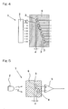
- Fig. 7 illustrates a schematic structural diagram showing a preferred embodiment of the present invention.
- the lubricant deterioration detecting device 1 is similar to that according to the above example shown in and described with reference to Fig. 5 , but differs therefrom in that the two light detecting components 3 and 4 are respectively made up of a detector 11A and 12A and an optical fiber 11C and 12C. More specifically, the light detecting component 3 is made up of the detector 11A and the optical fiber 11C having a base end connected with the detector 11A and a free end defining the light detecting face, while the light detecting components 4 is made up of the detector 12A and the optical fiber 12C having a base end connected with the detector 12A and a free end defining the light detecting face.
- a photodiode, a phototransistor, a CDS, a solar cell or a photomultiplier may be employed.
- the two detectors 11A and 12A are juxtaposed at the same position relative to the direction of travel of the rays of light and the two optical fibers 11C and 12C have varying lengths so that their free ends held displaced a predetermined distance d relative to the direction of travel of the rays of light. Accordingly, the respective positions of the light detecting faces of those two light detecting components 3 and 4 are displaced the predetermined distance d from each other relative to the direction of travel of the rays of light.
- Other structural features than those described above are similar to those employed in the above example
- the two light detecting components 3 and 4 are so arranged as to have their light detecting faces held displaced the distance d from each other relative to the direction of travel of the rays of light, the status of deterioration of the lubricant 6 can be detected without being adversely affected by thickness of the lubricant 6 itself, the intensity of the light source 2 and/or the distance from the light source to the light detecting components 3 and 4.
- Fig. 8 illustrates a schematic structural diagram showing the lubricant deterioration detecting device according to this example
- This lubricant deterioration detecting device 1 includes a light source 2, two light detecting components 3 and 4 for detecting rays of light emitted from the light source 2 and subsequently transmitted through an object to be detected in the form of a lubricant 6, a determining unit 5 for comparing respective signal strengths of outputs of the light detecting components 3 and 4 to detect the status of deterioration of the lubricant 6, and a light amount adjusting unit 7 for adjusting the amount of light emitted by the light source 2.
- the lubricant 6 forming an object to be detected is a lubricant filled within, for example, a bearing assembly.
- the light detecting components 3 and 4 which have their light detecting faces displaced a predetermined distance d in position in a direction of travel of the rays of light, are coupled with each other to form an integrated component part. Also, the two detecting elements 3 and 4 are arranged within the lubricant 6. Hence, the difference in thickness of the lubricant defined as a distance from a light incident surface of the lubricant 6 to the light detecting face of each of the light detecting components 3 and 4 is a value expressed by d.
- an LED, an incandescent bulb, a semiconductor laser diode, an EL, an organic EL or a fluorescent tube may be employed.
- a photodiode, a phototransistor, a CDS, a solar cell or a photomultiplier may be employed.
- the determining unit 5 is employed in the form of a differential amplifying circuit capable of determining the difference between the respective signal strengths of the outputs of the two light detecting components 3 and 5, but the present invention may not always limited thereto and any circuit configuration capable of determining the ratio of the signal strengths of the respective outputs of the two light detecting components 3 and 4 may be employed.
- the light amount adjusting unit 7 is operable to adjust the amount of light emitted from the light source 2 so that an output of one of the two light detecting components 3 and 4 that is closest to the light source 2, that is, an output of the light detecting component 3 (or the amount of light incident on the light detecting component 3) can represent a predetermined proper constant value (or a value within a constant range) by judging based on an output of the light detecting component 3.
- the proper constant value (or the value within the constant range) represented by the output of the light detecting component 3 means a value representing proper output of the light detecting component 3 corresponding to the amount of light received thereby without being saturated.
- the amount of light received by the light detecting component 4 remote from the light source 2 does not exceed the amount of light received by the light detected element 3 closest to the light source 2 and, therefore, by setting the output of the light detecting component 3 to a value as large as possible unless saturated, a highly precise detecting system can be obtained.
- the light amount adjusting unit may be composed of either an electronic circuit or that having a calculator or a built-in computer. Also, adjustment of the amount of light of the light source 2 accomplished by the light amount adjusting unit 7 may be performed either automatically continuously or intermittently only at the time of detection for the status of deterioration of the lubricant 6. In addition, where heat evolution of the light source 2 is requested to be suppressed or the maximum amount of light is desired to be increased, it is preferred that the light source 2 may be lit only at the time of detection of the status of deterioration of the lubricant 6, instead of being lit continuously.
- the constant ⁇ in the equation (4) above varies depending on the status of the lubricant 6.
- foreign matter such as, for example, powdery wear debris are admixed into the lubricant 6 as the bearing assembly is used in practice, and the constant ⁇ increases with an increase of the amount of the alien substance admixed.
- the determining unit 5 determines the ratio of the signal strengths of the two light detecting components 3 and 4 as hereinabove described, the light transmittance of light having traveled along an optical path of the distance d in the lubricant 6 is detected and, hence, it is possible to estimate from the value of the detected output the amount of the alien substance admixed into the lubricant 6. Also, since an increase of the amount of the alien substance admixed means a progress of deterioration taking place in the lubricant 6, the determining unit 5 can detect the status of deterioration of the lubricant 6 from the amount of the alien substance estimated.
- the determining unit 5 referred to above may be of a type capable of determining the difference between the signal strengths of the two detecting elements 3 and 4 referred to above. Since even in such case the determining unit 5 determines the light transmittance of the light transmitted the distance d in the lubricant 6, the amount of the alien substance admixed into the lubricant 6 can be estimated from the detected output thereof and, in turn, the status of deterioration of the lubricant 6 can be detected from the estimated amount of the alien substance admixed.
- the light amount adjusting unit 7 automatically adjusts the amount of light of the light source 2 (to allow the output of the light detecting component 4 to attain a proper value) so that the output of the light detecting component 3 can attain a predetermined proper constant value (or a value within the constant range) and, accordingly, a stabilized detection can be accomplished.
- this lubricant deterioration detecting device 1 is so designed and so configured that while the two light detecting components 3 and 4 are arranged with their light detecting faces held displaced the distance d from each other relative to the direction of travel of rays of light, the signal strengths of the outputs of the two light detecting components 3 and 4 can be compared by the determining unit 5 to detect the status of deterioration of the lubricant 6, and the amount of light of the light source 2 is automatically adjusted by the light amount adjusting unit 7. Accordingly the status of deterioration of the lubricant 6 can be detected without being adversely affected by the thickness of the lubricant 6 itself, the intensity of the light source 2 and/or the distance from the light source 2 to the light detecting components 3.
- the degree of freedom of arrangement comes to be high and construction is possible to accommodate to the limited available space for installation.
- the status of deterioration of the lubricant 6 is detected by comparing the respective signal strengths of the outputs of the two light detecting components 3 and 4
- a stable detection can be accomplished without being adversely affected by common mode noises such as a power source variation.
- arrangement of the two light detecting components 3 and 4 within the lubricant 6 is effective in that influences brought about by a temperature dependent change in characteristic can be counterbalanced among the two light detecting components 3 and 4 and, accordingly, a highly accurate detection can be accomplished.
- the result of detection can be made based on a change in temperature by disposing a temperature sensor in proximity of the light detecting components 3 and 4 for monitoring the temperatures of the lubricant 6 and the light detecting components 3 and 4. More specifically, for example, a circuit may be employed for correcting the detection signal generated at the temperature measured at the time of actual use, if a change in detection signal with change in temperature is beforehand measured. In such case, by sensing the temperature of the lubricant 6, it is possible to avoid the possibility that a change in detection signal with change in ambient temperature would be erroneously determined as resulting from deterioration of the lubricant 6. In this way, an accurate detection can be accomplished.
- the determining unit 5 may include a comparing circuit for comparing a detection signal, which is obtained by comparing the respective signal strengths of the outputs from the two light detecting components 3 and 4 with each other, with a predetermined reference value.
- a comparing circuit for comparing a detection signal, which is obtained by comparing the respective signal strengths of the outputs from the two light detecting components 3 and 4 with each other, with a predetermined reference value.
- Fig. 9 illustrates a schematic structural diagram showing an example of the present disclosure.
- the lubricant deterioration detecting device 1 according to this example is similar to that according to the above example shown in and described with particular reference to Fig. 8 , but differs therefrom in that the light amount adjusting unit 7 is designed to adjust the amount of light emitted from the light source 2 so that an output of one of the two light detecting components 3 and 4, that is remotest to the light source 2, that is, an output of the light detecting component 4 (or the amount of light incident on the light detecting component 4) can represent a predetermined proper constant value (or a value within a constant range) by judging based on an output of the light detecting component 4.
- Fig. 10 illustrates a schematic structural diagram showing a preferred embodiment of the present invention.
- the lubricant deterioration detecting device 1 according to this embodiment is similar to that according in the above example shown in and described with reference to Fig. 8 , but differs therefrom in that the two light detecting components 3 and 4 are respectively made up of detectors 11A and 12A and light guide elements 11B and 12B.
- the light detecting components 3 is made up of the detector 11A and the light guide element 11B having a base end connected with the detector 11A and a free end forming the light detecting face
- the light detecting component 4 is made up of the detector 12A and the light guide element 12B having a base end connected with the detector 12A and a free end defining the light detecting face.
- a photodiode, a phototransistor, a CDS, a solar cell or a photomultiplier may be employed.
- the two detectors 11A and 12A are juxtaposed at the same position relative to the direction of travel of the rays of light and the two light guide elements 11B and 12B have varying lengths so that their free ends are held displaced the predetermined distance d from each other relative to the direction of travel of the rays of light. Accordingly, the respective positions of the light detecting faces of those two light detecting components 3 and 4 are displaced the predetermined distance d from each other relative to the direction of travel of the rays of light.
- Each of the light guide elements 11B and 12B is made of a transparent material such as, for example, a cylindrical synthetic resin or glass and the free end thereof, which defines the light detecting face, represents a transparent round window, and an outer peripheral surface of each of the light guide elements 11B and 12B is coated with a reflective material. It is to be noted that each of the light guide elements 11B and 12B may not be always limited to that having a cylindrical shape, but may have a rectangular sectioned tubular shape. Other structural features than those described above are similar those according to the above example.
- the two light detecting components 3 and 4 are arranged with their light detecting faces displaced from each other the distance d relative to the direction of travel of the rays of light, the status of deterioration of the lubricant 6 can be detected without being adversely affected by the thickness of the lubricant 6 itself, the intensity of the light source 2 and/or the distance from the light source 2 to the light detecting components 3 and 4.
- the light amount adjusting unit 7 may be so designed as to adjust the amount of light of the light source 2 based on the output of the light detecting component 4, that is remotest from the light source 2.
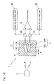
- Fig. 11 illustrates a schematic structural diagram showing an eighth preferred embodiment of the present invention.
- the lubricant deterioration detecting device 1 according to this embodiment is similar to that according to the above example shown in and described with reference to Fig. 8 , but differs therefrom in that the two light detecting components 3 and 4 are respectively made up of a detector 11A and 12A and an optical fiber 11C and 12C.
- the light detecting component 3 is made up of the detector 11A and the optical fiber 11C having a base end connected with the detector 11A and a free end defining the light detecting face
- the light detecting component 4 is made up of the detector 12A and the optical fiber 12C having a base end connected with the detector 12A and a free end defining the light detecting face.
- a photodiode, a phototransistor, a CDS, a solar cell or a photomultiplier may be employed.
- the two detectors 11A and 12A are juxtaposed at the same position relative to the direction of travel of the rays of light and the two optical fibers 11C and 12C have their free ends held displaced a predetermined distance d relative to the direction of travel of the rays of light, as is the case with the embodiment shown in and described with reference to Fig. 10 .
- the two detectors 11A and 12A are juxtaposed at the same position relative to the direction of travel of the rays of light and the two optical fibers 11C and 12C have different lengths so that the free ends thereof can be held displaced from each other a predetermined distance d relative to the direction of travel of the rays of light. Accordingly, the respective positions of the light detecting faces of those two light detecting components 3 and 4 are displaced the predetermined distance d from each other relative to the direction of travel of the rays of light.
- Other structural features than those described above are similar to those employed in the above example.
- the two light detecting components 3 and 4 are so arranged as to have their light detecting faces held displaced the distance d from each other relative to the direction of travel of the rays of light, the status of deterioration of the lubricant 6 can be detected without being adversely affected by thickness and/or light transmittance of the lubricant 6 itself, the intensity of the light source 2 and/or the distance from the light source to the light detecting components 3 and 4.
- Fig. 12 illustrates a schematic structural diagram showing the lubricant deterioration detecting device according to this example.
- This lubricant deterioration detecting device 1 includes a light source 2, two light detecting components 3 and 4 for detecting rays of light emitted from the light source 2 and subsequently transmitted through an object to be detected in the form of a lubricant 6, amplifying units 20 and 21 for amplifying respective outputs of the two light detecting components 3 and 4, a determining unit 5 for comparing respective signal strengths of the outputs amplified by those amplifying units 20 and 21 to detect the status of deterioration of the lubricant 6, and gain adjusting units 24 and 25 for adjusting respective gains of the amplifying units 20 and 21.
- the lubricant 6 forming an object to be detected is a lubricant filled within, for example, a bearing assembly.
- the light detecting components 3 and 4 which have their light detecting faces displaced a predetermined distance d in position in a direction of travel of the rays of light, are coupled with each other to form an integrated component part. Also, the two detecting elements 3 and 4 are arranged within the lubricant 6. In this way, the difference in thickness of the lubricant defined as a distance from a light incident surface of the lubricant 6 to the light detecting face of each of the light detecting components 3 and 4 is a value expressed by d.
- an LED for the light source 2, an LED, an incandescent bulb, a semiconductor laser diode, an EL, an organic EL or a fluorescent tube may be employed. Also, for each of the light detecting components 3 and 4, a photodiode, a phototransistor, a CDS, a solar cell or a photomultiplier may be employed. In Fig.
- the determining unit 5 is employed in the form of a differential amplifying circuit capable of determining the difference between the respective signal strengths of the outputs of the light detecting components 3 and 4 amplified by the respective amplifying units 20 and 21, but the present invention may not always limited thereto and any circuit configuration capable of determining the ratio of the signal strengths of the respective outputs of the two light detecting components 3 and 4 may be employed.
- Each of the gain adjusting units 24 and 25 is operable to adjust the gain of the associated amplifying units 20 and 21 so that the output of the respective light detecting component 3 and 4 can attain a value within a predetermined range.
- Fig. 13 illustrates a constructional example of the amplifying unit 20 (21) and the associated gain adjusting unit 24 (25).
- the amplifying unit 20 (21) includes two, amplifiers 22 and 23, connected with each other in series, having respective constant gains A1 and A2.
- the gain of the amplifying unit 20 (21) as a whole is obtained from A1 x A2, in the case of the maximum amplification factor.
- the gain adjusting unit 24 (25) is made up of a comparator 26 and a switch 27.
- the comparator 26 is operable to compare an output from the amplifier 23 with a reference value and, in the event that the output of the amplifier 23 exceeds the reference value, it determines that that output from the amplifier 23 is in an overflowing condition and then generates a command to trigger the switch 27 so that the overall gain of the amplifying unit 20 (21) can be switched from A1 x A2 to A1. While the output of the amplifying unit 20 (21) is supplied to the determining unit 5 in the subsequent stage as an output for comparison, the determining unit 5 detects the status of deterioration (the light transmittance) of the lubricant 6 with information on the gain of the comparator 26 taken into consideration.
- Fig. 14 illustrates another constructional example of the amplifying unit 20 (21) and the gain adjusting unit 24 (25).
- the amplifying unit 20 (21) is made up of two amplifiers 22 and 23, connected with each other in parallel, having respective constant gains A1 and A2.
- the gain A1 is rendered to be a low gain and the gain A2 is rendered to be a high gain.
- Other structural features are similar to those shown in and described with reference to Fig. 13 .
- the operation thereof is also similar to that of the constructional example shown in and described with reference to Fig.
- the number of the amplifiers forming the amplifying unit 20 (21) is not always limited to two such as shown, a multitude of amplifiers may be employed therefor.
- Fig. 15 illustrates a further constructional example of the amplifying unit 20 (21) and the gain adjusting unit 24 (25).
- the amplifying unit 20 (21) is structured in the form of an inverting amplifier that is made up of an operational amplifier 28 and parallel connected current-voltage converting resistors R1 and R2 connected with each other in parallel.
- the respective light detecting component 3 (4) in the form of photodiode is connected in series with the two resistors R1 and R2 connected with each other in parallel.
- the resistor R1 is set to have a low resistance and the resistor R2 is set to have a high resistance.
- the gain adjusting unit 24 (25) is made up of a comparator 26 and a switch 27.
- the comparator 26 is operable to compare an output from the operational amplifier 28 with a reference value and, in the event that the output of the operational amplifier 28 exceeds the reference value, it determines that an output from the amplifier 23 is in an overflowing condition and then generates a command to trigger the switch 27.
- the resistor which is to be used for the current-voltage conversion can be switched from resistor R2 to resistor R1 to thereby lower the overall gain.
- Fig. 16 illustrates a still further constructional example of the amplifying unit 20 (21) and the gain adjusting unit 24 (25).
- the amplifying unit 20 (21) is employed in the form of a voltage controlled amplifier (VCA) 29 and the gain adjusting unit 24 (25) is employed in the form of a control voltage generator 30.
- the control voltage generator 30 compares an output of the voltage controlled amplifier 29 with a reference value in order to feedback an output voltage, which is a result of the comparison performed thereby to the voltage controlled amplifier 29, whereby the gain of the voltage controlled amplifier 29 is changed by this output voltage.
- this constructional example can have a function equivalent to the switching performed by the switch 27 in any one of the constructional examples hereinabove described. In such case, a change of the gain of the voltage controlled amplifier 29 may be in a multi-step fashion or a non-step fashion.
- the constant ⁇ in the equation (4) described previously varies depending on the status of the lubricant 6.
- foreign matter such as, for example, powdery wear debris are admixed into the lubricant 6 as the bearing assembly is used in practice and, accordingly, the constant ⁇ increases with an increase of the amount of the alien substance admixed.
- the determining unit 5 determines the ratio of the signal strengths of the respective outputs of the light detecting components 3 and 4, which have been amplified by the amplifying units 20 and 21, the light transmittance of light having traveled the distance d within the lubricant 6 is detected and, hence, it is possible to estimate from the value of the detected output the amount of the alien substance admixed into the lubricant 6. Also, since an increase of the amount of the alien substance admixed means a progress of deterioration taking place in the lubricant 6, the determining unit 5 can detect the status of deterioration of the lubricant 6 from the amount of the alien substance estimated.
- the determining unit 5 may be of a type capable of determining the difference between the respective signal strengths of the outputs of the two light detecting components 3 and 4 which have been amplified by the amplifying units 20 and 21. Even in this case, the determining unit detects the light transmittance of rays of light transmitted the distance d within the lubricant 6 and, accordingly, the amount of the alien substance admixed into the lubricant 6 can be estimated from the detected output thereof and the status of deterioration of the lubricant 6 can accordingly detected from the amount of the alien substances so estimated.
- the gain adjusting unit 24 lowers the gain of the amplifying unit 20. Accordingly, the output of the light detecting component 3 amplified by the amplifying unit 20 can be adjusted to attain the value within the predetermined range and is then supplied to the determining unit 5 as an output for comparison purpose.
- the determining unit 5 compares the output of the light detecting component 3 so adjusted in the way described above, and the value of the output of the other light detecting component 4 amplified by the amplifying unit 21 with each other to thereby detect the light transmittance of the light traveling the distance d in the lubricant 6 (the status of deterioration of the lubricant 6). In such case, during the detection process taking place in the determining unit 5, the change of the gain effected by the amplifying unit 20 is taken into consideration.
- the output of the light detecting component 3 may represent a value exceeding the value within the predetermined range and, on the other hand, the output of the other light detecting component 4 may represent a value lower than the value within the predetermined range.
- the gain adjusting unit 24 lower the gain of the amplifying unit 20, but the gain adjusting unit 25 increases the gain of the amplifying unit 21.
- the output of the light detecting component 3 amplified by the amplifying unit 20 and the output of the light detecting component 4 amplified by the amplifying unit 21 are adjusted to represent the respective values falling within the predetermined ranges and are then supplied to the determining unit 5 for comparison purpose.
- the determining unit 5 compares the respective amplified outputs of the light detecting components 3 and 4 with each other to thereby detect the light transmittance of the light traveling the distance d in the lubricant 6 (the status of deterioration of the lubricant 6). In such case, during the detection process taking place in the determining unit 5, the change of the gains effected by the amplifying units 20 and 21, respectively, are taken into consideration.
- the two light detecting components 3 and 4 are so arranged that their light detecting faces are held displaced the distance d from each other relative to the direction of travel of the rays of light, and the respective outputs of those two light detecting components 3 and 4 are, after having been amplified by the amplifying units 20 and 21, compared with each other by the determining unit 5 to thereby detect the status of deterioration of the lubricant 6.
- the gain adjusting units 24 and 25 automatically adjust the respective gains of the amplifying units 20 and 21 so that the outputs of the light detecting components 3 and 4 amplified by the amplifying units 20 and 21, respectively, can represent values within the predetermined range.
- the status of deterioration can be stably detected without being adversely affected by the thickness of the lubricant 6 itself, the light transmittance thereof, the intensity of the light source 2 and/or the distance from the light source 2 to the light detecting components 3 and 4.
- the degree of freedom of arrangement comes to be high and construction is possible to accommodate to the limited available space for installation.
- the status of deterioration of the lubricant 6 is detected by comparing the respective outputs of the light detecting components 3 and 4, a stable detection can be accomplished without being adversely affected by common mode noises such as a power source variation.
- the light detecting components 3 and 4 are arranged within the lubricant 6, influences brought about by a temperature dependent change in characteristic of those two light detecting components 3 and 4 can be counterbalanced and, accordingly, a highly accurate detection can be accomplished.
- the result of detection can be made based on a change in temperature by disposing a temperature sensor in proximity of the light detecting components 3 and 4 for monitoring the temperatures of the lubricant 6 and the light detecting components 3 and 4. More specifically, for example, a circuit may be employed for correcting the detection signal generated at the temperature measured at the time of actual use, if a change in detection signal with change in temperature is beforehand measured. In such case, by sensing the temperature of the lubricant 6, it is possible to avoid the possibility that a change in detection signal with change in ambient temperature would be erroneously determined as resulting from deterioration of the lubricant 6. In this way, an accurate detection can be accomplished.
- the amplifying units 20 and 21 may be used in the following manner depending on the signal strengths of the outputs of the light detecting components 3 and 4.
- Fig. 17 illustrates a schematic structural diagram showing a preferred embodiment of the present invention.
- This lubricant deterioration detecting device 1 according to this embodiment is similar to that according to the above example shown in and described with reference to Fig. 12 , but differs therefrom in that each of the light detecting components 3 and 4 includes a detector 11A and 12A and a light guide element 11B and 12B.
- the light guide element 3 is made up of the detector 11A and the light guide element 11B having a base end connected with the detector 11A and a free end defining a light detecting face
- the light detecting component 4 is made up of the detector 12A and the light guide element 12B having a base end connected with the detector 12A and a free end defining a light detecting face.
- a photodiode, a phototransistor, a CDS, a solar cell or a photomultiplier may be employed.
- the two detectors 11A and 12A are juxtaposed at the same position relative to the direction of travel of the rays of light.
- each of the light guide elements 11B and 12B has respective varying lengths so that their free ends are held displaced the predetermined distance d from each other relative to the direction of travel of the rays of light. Accordingly, the respective positions of the light detecting faces of those two light detecting components 3 and 4 are displaced the predetermined distance d from each other relative to the direction of travel of the rays of light.
- Each of the light guide elements 11B and 12B is made of a transparent material such as, for example, a cylindrical synthetic resin or glass and the free end thereof, which defines the light detecting face, represents a transparent round window, and an outer peripheral surface of each of the light guide elements 11B and 12B is coated with a reflective material. It is to be noted that each of the light guide elements 11B and 12B may not be always limited to that having a cylindrical shape, but may have a rectangular sectioned tubular shape. Other structural features than those described above are similar to those employed in the above example.
- the two light detecting components 3 and 4 are so arranged as to have their light detecting faces held displaced the distance d from each other relative to the direction of travel of the rays of light, the status of deterioration of the lubricant 6 can be detected without being adversely affected by thickness or light transmittance of the lubricant 6 itself, the intensity of the light source 2 and/or the distance from the light source to the light detecting components 3 and 4.
- Fig. 18 illustrates a schematic structural diagram showing an eleventh preferred embodiment of the present invention.
- the lubricant deterioration detecting device 1 according to this embodiment is similar to that according to the above example shown in and described with reference to Fig. 12 , but differs therefrom in that each of the two light detecting components 3 and 4 is made up of a detector 11A and 12A and an optical fiber 11C and 12C.
- the light detecting component 3 is made up of the detector 11A and the optical fiber 11C having a base end connected with the detector 11A and a free end defining the light detecting face
- the light detecting component 4 is made up of the detector 12A and the optical fiber 12C having a base end connected with the detector 12A and a free end defining the light detecting face.
- a photodiode, a phototransistor, a CDS, a solar cell or a photomultiplier may be employed.
- the two detectors 11A and 12A are juxtaposed at the same position relative to the direction of travel of the rays of light and the two optical fibers 11C and 12C have respective lengths so that their free ends are held displaced the predetermined distance d from each other relative to the direction of travel of the rays of light. Accordingly, the respective positions of the light detecting faces of those two light detecting components 3 and 4 are displaced the predetermined distance d from each other relative to the direction of travel of the rays of light.
- Other structural features than those described above are similar to those employed in the above example.
- the two light detecting components 3 and 4 are so arranged as to have their light detecting faces held displaced the distance d from each other relative to the direction of travel of the rays of light, the status of deterioration of the lubricant 6 can be detected without being adversely affected by thickness or light transmittance of the lubricant 6 itself, the intensity of the light source 2 and/or the distance from the light source to the light detecting components 3 and 4.
- FIG. 19 illustrates a schematic structural diagram of the lubricant deterioration detecting device according to this embodiment.
- This lubricant deterioration detecting device 1 includes a bundled optical fiber array 10 made up of two bundles of optical fibers 11C and 12C which have their free ends displaced a predetermined distance d from each other, detectors 11A and 12A connected with base end of the optical fiber bundle 11C and base end of the optical fiber bundle 12C, respectively, a light source 2 positioned at a location confronting a free end of the bundled optical fiber array 10, and a comparing unit 5 for comparing signal outputs of the two detectors 11A and 12A to measure the light transmittance of the lubricant 6.
- a position proximate to the free end of the bundled optical fiber array 10 and adjacent the light source 2 is chosen to be a site of the lubricant 6 and respective free ends of the optical fibers 11C and 12C, which define their light detecting faces, are held within the lubricant 6.
- a temperature sensor 8 is provided in proximity of the free end of the bundled optical fiber array 10.
- Each of the bundles of optical fibers 11C and 12C is made up of a plurality of optical fibers, and a total light receiving surface area of one of the bundles of optical fibers 11C is chosen to be equal to that of the other of the bundles of optical fibers 12C. Except that the bundles of optical fibers 11C and 12C have respective free ends displaced from each other and also have respective base ends confronting the different detectors 11A and 12A, they are of the same construction.
- an LED for the light source 2, an LED, an incandescent bulb, a semiconductor laser diode, an EL, an organic EL or a fluorescent tube may be employed. Also, for each of the detectors 3 and 4, a photodiode, a phototransistor, a CDS, a solar cell or a photomultiplier may be employed. In Fig.
- the determining unit 5 is shown as including a differential amplifier 16 for determining the difference between the respective signal strengths of the output of the detectors 11A and 12A, respectively, a determining section 14 for comparing a signal output of this differential amplifier 16 with a reference value, and a correcting unit 13 for correcting an output of the determining unit 5 in reference to a detected value of the temperature sensor 8, but the present invention may not be always limited thereto and the determining unit 5 may have a circuit configuration operable to determine the ratio between the signal strengths of the outputs of those two detectors 11 A and 12A.
- the constant ⁇ in the equation (4) described previously varies depending on the status of the lubricant 6.
- the lubricant 6 is of a kind filled in the bearing assembly
- foreign matter such as, for example, powdery wear debris are admixed into the lubricant 6 as the bearing assembly is used in practice and, accordingly, the constant ⁇ increases with an increase of the amount of the alien substance admixed.
- oxidization and discoloring occur as deterioration of the lubricant proceeds and, therefore, where the lubricant 6 is a lubricating agent, the constant ⁇ increases as the lubricating agent is deteriorated.
- the determining unit 5 determines the ratio between the signal strengths of the two detectors 11A and 12A, the light transmittance of light traveling the optical distance d in the lubricant 6 is measured and, therefore, based on the value of the detected output, the amount of the alien substance admixed in the lubricant can be estimated or the status of deterioration of the lubricant can be detected.
- the difference between the respective signal strengths of the two detectors 11A and 12A is determined by means of the differential amplifier 16 as is the case with Fig. 19 , the light transmittance of the light traveling the optical distance d in the lubricant 6 is measured. For this reason, based on the detected output, the amount of the alien substance admixed in the lubricant can be estimated or the status of deterioration of the lubricant can be detected.
- this lubricant deterioration detecting device 1 is so designed that a bundled optical fiber array 10 is provided, which is made up of two bundles of optical fibers 11C and 12C having their free ends displaced a predetermined distance d from each other, in combination with the two detectors 11A and 12A connected with base ends of the optical fiber bundle 11C and base end of the optical fiber bundle 12C, respectively, also with the light source 2 positioned at a location confronting a free end of the bundled optical fiber array 10, while a position proximate to the free end of the bundled optical fiber array 10 and adjacent the light source 2 is chosen to be the site of the lubricant 6 so that the transmittance of the lubricant 6 can be measured by comparing, with the determining unit 5.
- the light transmittance of a lubricant 6 can be stably and accurately measured without being adversely affected by the thickness of the lubricant 6 itself, the amount of the lubricant 6, the intensity of the light source 2 and the distance from the light source 2 to the detectors 11A and 12A.
- the degree of freedom of arrangement comes to be high and construction is possible to accommodate to the limited available space for installation.
- the light transmittance of the lubricant 6 is detected by comparing the respective signal outputs of the detectors 11A and 12A, a stable detection can be accomplished without being adversely affected by common mode noises such as a power source variation.
- the bundled optical fiber array 10 is employed, a sufficient light receiving surface area can be secured on the light receiving side. For this reason, not only can a sufficient light receiving strength can be obtained with the detectors 11A and 12A, but any variation in thickness of the lubricant 6 brought about by the position can be cancelled and, therefore, a stable measurement of the light transmittance can be accomplished.
- the determining unit 5 shown in Fig. 19 since the temperature sensor 8 disposed in proximity of the free end of the bundled optical fiber array 10 detects the temperature of the lubricant 6 and the detectors 11A, 12A to thereby measure the temperature dependent characteristic of the lubricant based on the detected value thereof, or apply the correction appropriate to the change in temperature by the correcting unit 13 to the result of measurement based on the detected value thereof. Accordingly, it is possible to avoid the possibility that a change in measured value resulting from change of the ambient temperature would be erroneously determined as having resulted from the deterioration of the lubricating agent which is the lubricant 6. In this way, a further accurate measurement can be accomplished.
- the determining unit 14 for comparing the detection signal which can be obtained by comparing the respective signal output of the two detectors 11A and 12A, respectively, with each other, with the predetermined reference value, it can readily determined that the status of deterioration of, for example, a lubricating agent which is the lubricant 6, is above a predetermined level and, thus, it can be used as an indication of the time of replacement.
- Fig. 20 illustrates a specific constructional example of the light receiving side of the lubricant deterioration detecting device 1 shown in Fig. 19 .
- the two bundles of optical fibers 11C and 12C forming the bundled optical fiber array 10 are so bundled together that a free end thereof, which define the light detecting face, may represent a planar shape, for example, a round shape.
- the free end of the bundled optical fiber array 10 is planarly arranged to represent a planar shape, averaging can be made even though the distribution of thickness of the lubricant 6 varies and, therefore, a stable measurement can be accomplished without such variation adversely affecting the measured value. Also, merely positioning of the light source 2 (in Fig. 19 ) in face-to-face relation with the bundled optical fiber array 10 having the lubricant 6 deposited on the free end face thereof makes it possible to accomplish the stable measurement. It is to be noted that in such case, it is preferable to increase the surface area of the light source 2 to suit to the light receiving surface area of the bundled optical fiber array 10 or to employ the light source 2 in the form of a planar light emitting body.
- Fig. 21 illustrates another specific constructional example of the lubricant deterioration detecting device 1 shown in Fig. 19 .
- the two bundles of optical fibers 11C and 12C forming the bundled optical fiber array 10 are arranged in line.
- the light receiving unit can be constructed to have a thin structure and, therefore, the light transmittance of a lubricant 6 distributed in a planar shape can be measured. It is to be noted that even in this case, it is preferable to employ the light source 5 in the form having a linear shape so that the light receiving efficiency can be increased.
- Fig. 22 illustrates a sectional view showing a detecting device incorporated bearing assembly having the lubricant detection detecting device 1 of the structure described hereinabove, which is used in a railway vehicle bearing part.
- the railway vehicle bearing unit in this case includes a detecting device incorporated bearing assembly 31, and an oil slinger 32 and a rear lid 33, which are accessory components that are provided in contact with opposite ends of an inner ring 34.
- the bearing assembly 31 is in the form of a rolling bearing, more specifically a double row tapered roller bearing and includes split type inner rings 34 and 34, each provided for a row of rolling elements 36, an unitary outer ring 35, rows of rolling elements 36 and 36 and retainers 37.
- the rear lid 33 is mounted on a wheel axle 40 at a location closer to the midpoint thereof than the location of the bearing assembly 31 and has an outer periphery with which an oil seal 38 is slidingly engaged.
- the oil slinger 32 is mounted on the wheel axle 40 and has an outer periphery with which an oil seal 39 is slidingly engaged.
- the oil seals 38 and 39 arranged on opposite ends of the bearing assembly 31 serve to seal the lubricant within the bearing assembly 31 and, accordingly, the dust proofing and the resistance to water can be secured.
- the lubricant deterioration detecting device 1 is fitted intermediate between the rows of raceway surfaces defined in the inner diametric surface of an outer ring 35 of the bearing device 31 for detecting the status of deterioration of the lubricant sealed within the bearing unit.
- the lubricant deterioration detecting device 1 is arranged in proximity to end faces of the rollers 36.
- the outer ring 35 is formed with a cable insertion hole 35a for passage therethrough of a wiring cable 19 of the lubricant deterioration detecting device 1, and a portion where the wiring cable 19 is inserted is treated to have a water resistance and an oil resistance.
- deterioration of the lubricant filled within the bearing unit can be accurately detected in real time or regularly.
- the necessity of replacement of the lubricant can be judged and it is possible to prevent the bearing device 31 from being damaged as a result of the defective lubricant.
- the necessity of replacement of the lubricant can be determined in reference to the output of the lubricant deterioration detecting device 1, the amount of the lubricant which may be discarded prior to the life time of use can be reduced.
- Fig. 23 illustrates another example of the detecting device incorporated bearing assembly.
- This detecting device incorporated bearing assembly 31 A is similar to the detecting device incorporated bearing assembly 31 shown in and described with reference to Fig. 22 , but differs therefrom in that the lubricant deterioration detecting device 1 is fitted to an inner surface of the oil seal 39. In such case, the lubricant deterioration detecting device 1 is arranged proximate to an end face of the retainer 37.
- Fig. 24 illustrates a further example of the detecting device incorporated bearing assembly.
- This detecting device incorporated bearing assembly 31B is similar to the detecting device incorporated bearing assembly 31 shown in and described with reference to Fig. 22 , but differs therefrom in that the lubricant deterioration detecting device 1 is fitted to one side of the raceway surface of the outer ring 35. Positioning of the lubricant deterioration detecting device 1 on one side of the raceway surface as hereinabove described is effective to assuredly detect the status of the lubricant then attributing to lubrication.
- the transmittance detecting device referred to above is so designed as to include a bundled optical fiber array made up of two bundles of optical fibers having their free end displaced relative to each other, with base ends of the optical fibers of the bundled optical fiber array connected with two light detectors one employed for each of the two bundles of optical fibers, a light source positioned in face-to-face relation with a free end of the bundled optical fiber array, and a determining unit for measuring the light transmittance of a sample by comparing signal outputs from the two light detectors, wherein a position adjacent the light source proximate to the free end of the bundled optical fiber array is chosen to be an area of placement of the sample.
- the lubricant deterioration detecting device shown in and described with reference to Fig. 19 is applied as an apparatus for detecting the transmittance of any other sample than the lubricant.
- the amount of light attenuated after having passed across the thickness of the sample, which corresponds to the displacement in position of the free ends of the two bundles of optical fibers can be detected by comparison of the signal outputs from the two detectors. For this reason, without being adversely affected by the thickness of the sample itself, the amount of the sample, the intensity of the light source and the distance from the light source to the light detectors, the light transmittance of the sample can be stably and accurately detected. As a result thereof, even when the transmittance detecting device is incorporated in, for example, the bearing assembly or the like, the degree of freedom of arrangement comes to be high and construction is possible to accommodate to the limited available space for installation.
- the optical fibers are employed and since a sufficient light receiving surface area can be secured on the light receiving side, not only can the intensity of received light be obtained with the light detectors, but also any variation in thickness of the sample depending on the position can be cancelled and, hence, even in this respect, the light transmittance can be stably measured.
Claims (18)
- Dispositif de détection de la détérioration du lubrifiant (1) qui comprend :une source lumineuse (2) ;une pluralité de composants de détection de la lumière (3) pour détecter des rayons de lumière émis par la source lumineuse et transmis par la suite à travers un lubrifiant (6), ladite pluralité de composants de détection de la lumière ayant des faces respectives de détection de la lumière dont la position est séquentiellement décalée, etune unité de détermination (5) pouvant fonctionner pour comparer les forces des signaux respectifs de sorties de la pluralité de composants de détection de la lumière afin de pouvoir ainsi détecter un état de détérioration du lubrifiant, dans lequel chacun des composants de détection de la lumière comprend un détecteur (11A) et un élément guide de la lumière (11B) présentant une extrémité sous forme d'une extrémité de base reliée au détecteur et l'autre extrémité sous forme d'une extrémité libre formant la face de détection de la lumière et les éléments guide de la lumière présentant des longueurs différentes de sorte que leurs extrémités libres occupent des positions respectives séquentiellement décalées d'une distance prédéterminée par rapport à la direction de passage des rayons de lumière.
- Le dispositif de détection de détérioration de lubrifiant selon la revendication 1, dans lequel l'unité de détermination est d'un type capable d'estimer une quantité de la substance étrangère mélangée au lubrifiant par comparaison des forces de signal.
- Le dispositif de détection de détérioration de lubrifiant selon la revendication 1, dans lequel chacun des composants de détection de la lumière comprend un détecteur et un élément guide de la lumière ayant une extrémité sous la forme d'une extrémité de base reliée au détecteur et l'autre extrémité sous la forme d'une extrémité libre formant la face de détection de la lumière.
- Le dispositif de détection de détérioration de lubrifiant selon la revendication 1, dans lequel chacun des composants de détection de la lumière comprend un détecteur et une fibre optique ayant une extrémité sous la forme d'une extrémité de base reliée au détecteur et l'autre extrémité sous la forme d'une extrémité libre formant la face de détection de la lumière.
- Le dispositif de détection de détérioration de lubrifiant selon la revendication 1, dans lequel l'unité de détermination est d'un type capable de calculer un facteur de transmission de la lumière du lubrifiant.
- Le dispositif de détection de détérioration de lubrifiant selon la revendication 1, dans lequel l'unité de détermination comprend une section de sélecteur permettant d'exclure, à partir des signaux de sortie de la pluralité de composants de détection de la lumière, les signaux de sortie des composants de détection de la lumière qui génèrent une sortie saturée, et les signaux de sortie des composants de détection de la lumière indiquant une intensité lumineuse détectée qui n'atteigne pas une valeur prédéterminée, afin d'exploiter les signaux de sortie du reste des composants de détection de la lumière pour la détection de l'état de détérioration du lubrifiant.
- Le dispositif de détection de détérioration de lubrifiant selon la revendication 1, qui comprend deux composants de détection de la lumière.
- Le dispositif de détection de détérioration de lubrifiant selon la revendication 7, comprenant en outre un capteur de température placé à proximité des composants de détection de la lumière.
- Le dispositif de détection de détérioration de lubrifiant selon la revendication 7, comprenant en outre une unité de réglage de quantité de lumière pour régler une quantité de la lumière de la source lumineuse de telle sorte qu'une sortie de l'un des deux composants de détection de la lumière, qui est le plus proche de la source lumineuse, arrive à une valeur constante prédéterminée.
- Le dispositif de détection de détérioration de lubrifiant selon la revendication 7, comprenant en outre une unité de réglage de la quantité de lumière pour régler une quantité de lumière de la source lumineuse de telle sorte qu'une sortie de l'un des deux composants de détection de la lumière, qui est le plus éloigné de la source lumineuse, arrive à une valeur constante prédéterminée.
- Le dispositif de détection de détérioration de lubrifiant selon la revendication 7, comprenant en outre une unité d'amplification pour amplifier une sortie de chacun des composants de détection de la lumière et une unité pour régler le gain de l'unité d'amplification, dans lequel l'unité de détermination compare les sorties amplifiées par l'unité d'amplification pour détecter l'état de détérioration du lubrifiant, et dans lequel l'unité de réglage de gain règle le gain de l'unité d'amplification pour permettre aux sorties de chacun des composants de détection de la lumière, qui ont été amplifiées par l'unité d'amplification, d'atteindre une valeur dans une plage prédéterminée.
- Le dispositif de détection de détérioration de lubrifiant selon la revendication 1, comprenant deux composants de détection de la lumière, dans lequel chacun des composants de détection de la lumière comprend un détecteur et un faisceau de fibres optiques ayant une extrémité sous la forme d'une extrémité de base reliée à un détecteur et l'autre extrémité sous la forme d'une extrémité libre formant une face de détection de la lumière.
- Le dispositif de détection de détérioration de lubrifiant selon la revendication 12, comprenant en outre un capteur de température placé à proximité des extrémités libres des faisceaux de fibres optiques, et une unité de correction pour corriger une sortie de l'unité de détermination sur la base d'une valeur détectée du capteur de température.
- Le dispositif de détection de détérioration de lubrifiant selon la revendication 12, dans lequel chacune des extrémités libres respectives des faisceaux de fibres optiques est disposée en ligne.
- Le dispositif de détection de détérioration de lubrifiant selon la revendication 14, dans lequel la source lumineuse est sous la forme d'une source de lumière de forme linéaire correspondant à un agencement de forme linéaire des extrémités libres des faisceaux de fibres optiques.
- Le dispositif de détection de détérioration de lubrifiant selon la revendication 12, dans lequel les faisceaux de fibres optiques présentent des faces respectives d'extrémité libres disposées de façon plane.
- Le dispositif de détection de détérioration de lubrifiant selon la revendication 16, dans lequel la source lumineuse est une source lumineuse plane correspondant à la forme plane avec laquelle sont disposées les extrémités libres des faisceaux de fibres optiques.
- Ensemble de palier incorporant un dispositif de détection sur lequel est monté un dispositif de détection de détérioration de lubrifiant selon la revendication 1.
Applications Claiming Priority (6)
| Application Number | Priority Date | Filing Date | Title |
|---|---|---|---|
| JP2006024127A JP4836588B2 (ja) | 2006-02-01 | 2006-02-01 | 軸受の潤滑剤劣化検出装置および検出装置付き軸受 |
| JP2006029337A JP2007212160A (ja) | 2006-02-07 | 2006-02-07 | 潤滑剤劣化検出装置および検出装置付き軸受 |
| JP2006029338A JP2007212161A (ja) | 2006-02-07 | 2006-02-07 | 透過率・潤滑剤劣化検出装置および検出装置付き軸受 |
| JP2006037546A JP2007218650A (ja) | 2006-02-15 | 2006-02-15 | 潤滑剤劣化検出装置および検出装置付き軸受 |
| JP2006042378A JP2007218841A (ja) | 2006-02-20 | 2006-02-20 | 潤滑剤劣化検出装置および検出装置付き軸受 |
| PCT/JP2007/000031 WO2007088701A1 (fr) | 2006-02-01 | 2007-01-26 | Detecteur de deterioration de lubrifiant et roulement avec detecteur |
Publications (3)
| Publication Number | Publication Date |
|---|---|
| EP1983204A1 EP1983204A1 (fr) | 2008-10-22 |
| EP1983204A4 EP1983204A4 (fr) | 2010-06-02 |
| EP1983204B1 true EP1983204B1 (fr) | 2013-03-13 |
Family
ID=38327283
Family Applications (1)
| Application Number | Title | Priority Date | Filing Date |
|---|---|---|---|
| EP07706283A Expired - Fee Related EP1983204B1 (fr) | 2006-02-01 | 2007-01-26 | Détecteur de deterioration de lubrifiant et ensemble de palier avec ledit détecteur |
Country Status (3)
| Country | Link |
|---|---|
| US (1) | US8436292B2 (fr) |
| EP (1) | EP1983204B1 (fr) |
| WO (1) | WO2007088701A1 (fr) |
Families Citing this family (14)
| Publication number | Priority date | Publication date | Assignee | Title |
|---|---|---|---|---|
| WO2007083520A1 (fr) * | 2006-01-23 | 2007-07-26 | Ntn Corporation | Detecteur de degradation de lubrifiant et palier equipe de ce detecteur |
| WO2008121693A1 (fr) * | 2007-03-30 | 2008-10-09 | University Of South Carolina | Stabilité améliorée pour système informatique optique |
| EP2449354B1 (fr) * | 2009-07-30 | 2020-06-03 | Halliburton Energy Services Inc. | Transformation d'intensité d'énergie |
| WO2012117970A1 (fr) * | 2011-03-03 | 2012-09-07 | Ntn株式会社 | Système de contrôle d'état pour dispositif de roulement et procédé de contrôle d'état |
| JP2013142626A (ja) * | 2012-01-11 | 2013-07-22 | Yamashin-Filter Corp | 不純物粒子測定装置 |
| GB201300362D0 (en) | 2013-01-09 | 2013-02-20 | Reckitt Benckiser Uk Ltd | Low cost senor system |
| EP3111175B1 (fr) * | 2014-02-24 | 2019-04-10 | Fresenius Kabi Deutschland GmbH | Appareil et procédé permettant de déterminer le niveau de liquide de sang récupéré dans un réservoir de collecte de sang d'un système de transfusion sanguine autologue |
| WO2015178822A1 (fr) * | 2014-05-19 | 2015-11-26 | Aktiebolaget Skf | Dispositif et procédé pour déterminer des propriétés de lubrifiant dans un roulement |
| WO2015178823A1 (fr) * | 2014-05-19 | 2015-11-26 | Aktiebolaget Skf | Agencement de palier et procédé de détermination de propriétés optiques d'un lubrifiant dans un palier |
| EP3095709B1 (fr) * | 2015-05-20 | 2018-01-10 | Goodrich Lighting Systems GmbH | Dispositif d'éclairage extérieur pour aéronef |
| US9279711B1 (en) * | 2015-07-21 | 2016-03-08 | Eric Guldalian | Optical sensor for a conventional tank gauge |
| US20180216022A1 (en) | 2017-01-27 | 2018-08-02 | Scott Rettberg | System and method for reducing friction, torque and drag in artificial lift systems used in oil and gas production wells |
| US20190137035A1 (en) * | 2017-11-03 | 2019-05-09 | Scott Rettberg | System and method for reducing friction, torque and drag in artificial lift systems used in oil and gas production wells |
| US10866257B2 (en) | 2017-11-21 | 2020-12-15 | Aktiebolaget Skf | Wheel hub bearing provided with a device for measuring the rotational speed |
Family Cites Families (25)
| Publication number | Priority date | Publication date | Assignee | Title |
|---|---|---|---|---|
| US3548657A (en) * | 1967-11-30 | 1970-12-22 | Maria Panerai | Device for an outside display of the level of a liquid contained within a tank |
| IT1048490B (it) * | 1974-09-12 | 1980-11-20 | Scherico Ltd | Metodo ed apparecchio per controllare liquidi entro contenitori trasparenti |
| US4080076A (en) * | 1976-07-28 | 1978-03-21 | Optronix Inc. | Suspended solids analyzer using multiple light sources and photodetectors |
| GB1588862A (en) * | 1978-05-11 | 1981-04-29 | Standard Telephones Cables Ltd | Measuring oil in water |
| US4277681A (en) * | 1979-10-04 | 1981-07-07 | Honeywell Inc. | Low radiation densitometer |
| JPS56153238A (en) * | 1980-04-26 | 1981-11-27 | Fuji Electric Co Ltd | Measuring device for organic polluting component in water |
| JPS626524Y2 (fr) * | 1980-11-10 | 1987-02-14 | ||
| JPS626524A (ja) | 1985-07-02 | 1987-01-13 | Pioneer Electronic Corp | Pwm駆動回路 |
| JPS6326557A (ja) * | 1986-07-18 | 1988-02-04 | Shikoku Keisoku Kogyo Kk | 液体状態判定方法 |
| JPH01272941A (ja) * | 1988-04-25 | 1989-10-31 | Matsushita Graphic Commun Syst Inc | 濃度監視装置 |
| JP3642602B2 (ja) * | 1994-03-04 | 2005-04-27 | アークレイ株式会社 | 尿中成分の測定装置 |
| CN1087429C (zh) * | 1994-03-04 | 2002-07-10 | 株式会社京都第一科学 | 同时定量分析数种尿中成分的测定方法及测定装置 |
| US5446531A (en) * | 1994-05-20 | 1995-08-29 | Honeywell Inc. | Sensor platform for use in machines for washing articles |
| RU2205382C2 (ru) * | 1995-04-06 | 2003-05-27 | Альфа Лаваль Агри Аб | Способ и устройство для количественного определения частиц в жидких средах |
| JPH1026584A (ja) * | 1995-06-23 | 1998-01-27 | Inter Tec:Kk | フローセル |
| JPH10281986A (ja) * | 1997-04-01 | 1998-10-23 | Shimadzu Corp | 米成分試験装置 |
| JPH10318920A (ja) * | 1997-05-16 | 1998-12-04 | Toto Denki Kogyo Kk | 流体濃度測定方法および装置 |
| JP2003139696A (ja) * | 2001-10-30 | 2003-05-14 | Toshiba Corp | 油劣化診断装置 |
| JP4029604B2 (ja) * | 2001-11-29 | 2008-01-09 | 日本精工株式会社 | 転がり軸受 |
| DE10228103A1 (de) | 2002-06-24 | 2004-01-15 | Bayer Cropscience Ag | Fungizide Wirkstoffkombinationen |
| US6960769B2 (en) * | 2002-10-03 | 2005-11-01 | Abb Inc. | Infrared measuring apparatus and method for on-line application in manufacturing processes |
| JP4269784B2 (ja) | 2002-12-03 | 2009-05-27 | 日本精工株式会社 | センサ付軸受 |
| JP2004309296A (ja) * | 2003-04-07 | 2004-11-04 | Horiba Ltd | 吸光式分析計 |
| JP2004340806A (ja) * | 2003-05-16 | 2004-12-02 | Nippon Soken Inc | 粒子濃度検出方法 |
| KR100504310B1 (ko) * | 2003-10-28 | 2005-07-28 | 한국과학기술연구원 | 자외선 형광특성을 이용한 오일 산화도 측정장치 |
-
2007
- 2007-01-26 WO PCT/JP2007/000031 patent/WO2007088701A1/fr active Application Filing
- 2007-01-26 EP EP07706283A patent/EP1983204B1/fr not_active Expired - Fee Related
- 2007-01-26 US US12/162,294 patent/US8436292B2/en active Active
Also Published As
| Publication number | Publication date |
|---|---|
| EP1983204A1 (fr) | 2008-10-22 |
| US8436292B2 (en) | 2013-05-07 |
| EP1983204A4 (fr) | 2010-06-02 |
| WO2007088701A1 (fr) | 2007-08-09 |
| US20090050827A1 (en) | 2009-02-26 |
Similar Documents
| Publication | Publication Date | Title |
|---|---|---|
| EP1983204B1 (fr) | Détecteur de deterioration de lubrifiant et ensemble de palier avec ledit détecteur | |
| EP1980840A1 (fr) | Detecteur de degradation de lubrifiant et palier equipe de ce detecteur | |
| EP1566626A1 (fr) | Dispositif pour la détection du gaz dans une contruction integrée | |
| JP2008026046A (ja) | 潤滑剤劣化検出装置および検出装置付き軸受 | |
| JP2007192769A (ja) | 潤滑剤劣化検出装置および検出装置付き軸受 | |
| CN102460122A (zh) | 使用带通滤波器的传感器 | |
| JP2008145353A (ja) | 液中粒子濃度検出装置 | |
| CN102460097B (zh) | 使用带通滤波器测量发射体的温度的气体传感器 | |
| JP2007212161A (ja) | 透過率・潤滑剤劣化検出装置および検出装置付き軸受 | |
| JP2007248337A (ja) | 潤滑剤劣化検出装置 | |
| JP2007212205A (ja) | 潤滑剤劣化検出装置および検出装置付き軸受 | |
| JP2007218650A (ja) | 潤滑剤劣化検出装置および検出装置付き軸受 | |
| JP2007212160A (ja) | 潤滑剤劣化検出装置および検出装置付き軸受 | |
| JP2007218841A (ja) | 潤滑剤劣化検出装置および検出装置付き軸受 | |
| JP4836588B2 (ja) | 軸受の潤滑剤劣化検出装置および検出装置付き軸受 | |
| KR100785244B1 (ko) | 강판의 도유량 측정방법 | |
| JP4812492B2 (ja) | 潤滑剤劣化検出装置およびセンサ付き軸受 | |
| JP2007239971A (ja) | センサ付き車輪用軸受装置 | |
| JP4745101B2 (ja) | 潤滑剤劣化検出装置およびセンサ付き軸受 | |
| JP4833046B2 (ja) | 軸受の潤滑剤劣化検出装置 | |
| JP2008026044A (ja) | 潤滑剤劣化検出装置および検出装置付き軸受 | |
| JP2007198857A (ja) | 潤滑剤劣化検出装置および検出装置付き軸受 | |
| JP2002521656A (ja) | 分光計の機能を試験する方法および故障検出装置を有する分光計 | |
| JP2008139139A (ja) | 軸受の潤滑剤劣化検出装置 | |
| JP2007292568A (ja) | 潤滑剤劣化検出装置および検出装置付き軸受 |
Legal Events
| Date | Code | Title | Description |
|---|---|---|---|
| PUAI | Public reference made under article 153(3) epc to a published international application that has entered the european phase |
Free format text: ORIGINAL CODE: 0009012 |
|
| 17P | Request for examination filed |
Effective date: 20080901 |
|
| AK | Designated contracting states |
Kind code of ref document: A1 Designated state(s): FR |
|
| DAX | Request for extension of the european patent (deleted) | ||
| RBV | Designated contracting states (corrected) |
Designated state(s): FR |
|
| A4 | Supplementary search report drawn up and despatched |
Effective date: 20100506 |
|
| RIC1 | Information provided on ipc code assigned before grant |
Ipc: G01N 33/28 20060101ALI20100423BHEP Ipc: G01N 33/30 20060101ALI20100423BHEP Ipc: G01N 21/85 20060101ALI20100423BHEP Ipc: G01N 21/59 20060101ALI20100423BHEP Ipc: F16C 41/00 20060101AFI20070910BHEP |
|
| 17Q | First examination report despatched |
Effective date: 20100526 |
|
| RIC1 | Information provided on ipc code assigned before grant |
Ipc: F16C 33/66 20060101ALI20120606BHEP Ipc: G01N 21/53 20060101ALI20120606BHEP Ipc: G01N 21/59 20060101ALI20120606BHEP Ipc: G01N 33/28 20060101ALI20120606BHEP Ipc: G01N 21/85 20060101ALI20120606BHEP Ipc: F16C 19/38 20060101ALI20120606BHEP Ipc: G01N 33/30 20060101ALI20120606BHEP Ipc: F16C 41/00 20060101AFI20120606BHEP Ipc: G01N 21/49 20060101ALI20120606BHEP Ipc: F16N 29/00 20060101ALI20120606BHEP |
|
| RIC1 | Information provided on ipc code assigned before grant |
Ipc: F16C 19/38 20060101ALI20120628BHEP Ipc: G01N 33/28 20060101ALI20120628BHEP Ipc: G01N 21/59 20060101ALI20120628BHEP Ipc: G01N 21/85 20060101ALI20120628BHEP Ipc: F16C 33/66 20060101AFI20120628BHEP Ipc: F16C 41/00 20060101ALI20120628BHEP Ipc: G01N 21/49 20060101ALI20120628BHEP Ipc: G01N 21/53 20060101ALI20120628BHEP Ipc: F16N 29/00 20060101ALI20120628BHEP |
|
| GRAP | Despatch of communication of intention to grant a patent |
Free format text: ORIGINAL CODE: EPIDOSNIGR1 |
|
| GRAC | Information related to communication of intention to grant a patent modified |
Free format text: ORIGINAL CODE: EPIDOSCIGR1 |
|
| GRAS | Grant fee paid |
Free format text: ORIGINAL CODE: EPIDOSNIGR3 |
|
| RIN1 | Information on inventor provided before grant (corrected) |
Inventor name: NAKAJIMA, AKIO Inventor name: TAKAHASHI, TORU |
|
| GRAA | (expected) grant |
Free format text: ORIGINAL CODE: 0009210 |
|
| AK | Designated contracting states |
Kind code of ref document: B1 Designated state(s): FR |
|
| PLBE | No opposition filed within time limit |
Free format text: ORIGINAL CODE: 0009261 |
|
| STAA | Information on the status of an ep patent application or granted ep patent |
Free format text: STATUS: NO OPPOSITION FILED WITHIN TIME LIMIT |
|
| 26N | No opposition filed |
Effective date: 20131216 |
|
| REG | Reference to a national code |
Ref country code: FR Ref legal event code: PLFP Year of fee payment: 10 |
|
| REG | Reference to a national code |
Ref country code: FR Ref legal event code: PLFP Year of fee payment: 11 |
|
| REG | Reference to a national code |
Ref country code: FR Ref legal event code: PLFP Year of fee payment: 12 |
|
| PGFP | Annual fee paid to national office [announced via postgrant information from national office to epo] |
Ref country code: FR Payment date: 20211217 Year of fee payment: 16 |
|
| PG25 | Lapsed in a contracting state [announced via postgrant information from national office to epo] |
Ref country code: FR Free format text: LAPSE BECAUSE OF NON-PAYMENT OF DUE FEES Effective date: 20230131 |