EP1978286B1 - Reibungsarmes schiebeglied, herstellungsvorrichtung dafür und verfahren zu dessen herstellung - Google Patents
Reibungsarmes schiebeglied, herstellungsvorrichtung dafür und verfahren zu dessen herstellung Download PDFInfo
- Publication number
- EP1978286B1 EP1978286B1 EP06843388.7A EP06843388A EP1978286B1 EP 1978286 B1 EP1978286 B1 EP 1978286B1 EP 06843388 A EP06843388 A EP 06843388A EP 1978286 B1 EP1978286 B1 EP 1978286B1
- Authority
- EP
- European Patent Office
- Prior art keywords
- forming roller
- recesses
- low
- sliding member
- workpiece
- Prior art date
- Legal status (The legal status is an assumption and is not a legal conclusion. Google has not performed a legal analysis and makes no representation as to the accuracy of the status listed.)
- Ceased
Links
- 238000004519 manufacturing process Methods 0.000 title claims description 46
- 238000000034 method Methods 0.000 title description 5
- 238000005259 measurement Methods 0.000 claims description 38
- 238000003754 machining Methods 0.000 claims description 28
- 230000002093 peripheral effect Effects 0.000 claims description 22
- 239000012530 fluid Substances 0.000 claims description 4
- 238000003384 imaging method Methods 0.000 claims 1
- 239000003921 oil Substances 0.000 description 25
- 238000012360 testing method Methods 0.000 description 21
- 230000000694 effects Effects 0.000 description 19
- 238000001514 detection method Methods 0.000 description 11
- 230000000052 comparative effect Effects 0.000 description 8
- 238000003825 pressing Methods 0.000 description 4
- 230000008602 contraction Effects 0.000 description 3
- 230000006866 deterioration Effects 0.000 description 3
- 238000011161 development Methods 0.000 description 3
- 230000018109 developmental process Effects 0.000 description 3
- 238000009826 distribution Methods 0.000 description 3
- 239000000314 lubricant Substances 0.000 description 3
- 239000010687 lubricating oil Substances 0.000 description 3
- 239000000463 material Substances 0.000 description 3
- 239000002184 metal Substances 0.000 description 3
- 238000010586 diagram Methods 0.000 description 2
- 229910000831 Steel Inorganic materials 0.000 description 1
- 230000015572 biosynthetic process Effects 0.000 description 1
- 230000001419 dependent effect Effects 0.000 description 1
- 238000006073 displacement reaction Methods 0.000 description 1
- 238000012986 modification Methods 0.000 description 1
- 230000004048 modification Effects 0.000 description 1
- 238000012545 processing Methods 0.000 description 1
- 230000000717 retained effect Effects 0.000 description 1
- 238000005096 rolling process Methods 0.000 description 1
- 239000010959 steel Substances 0.000 description 1
- XLYOFNOQVPJJNP-UHFFFAOYSA-N water Substances O XLYOFNOQVPJJNP-UHFFFAOYSA-N 0.000 description 1
Images


Classifications
-
- F—MECHANICAL ENGINEERING; LIGHTING; HEATING; WEAPONS; BLASTING
- F16—ENGINEERING ELEMENTS AND UNITS; GENERAL MEASURES FOR PRODUCING AND MAINTAINING EFFECTIVE FUNCTIONING OF MACHINES OR INSTALLATIONS; THERMAL INSULATION IN GENERAL
- F16J—PISTONS; CYLINDERS; SEALINGS
- F16J15/00—Sealings
- F16J15/16—Sealings between relatively-moving surfaces
- F16J15/162—Special parts or details relating to lubrication or cooling of the sealing itself
-
- F—MECHANICAL ENGINEERING; LIGHTING; HEATING; WEAPONS; BLASTING
- F16—ENGINEERING ELEMENTS AND UNITS; GENERAL MEASURES FOR PRODUCING AND MAINTAINING EFFECTIVE FUNCTIONING OF MACHINES OR INSTALLATIONS; THERMAL INSULATION IN GENERAL
- F16C—SHAFTS; FLEXIBLE SHAFTS; ELEMENTS OR CRANKSHAFT MECHANISMS; ROTARY BODIES OTHER THAN GEARING ELEMENTS; BEARINGS
- F16C17/00—Sliding-contact bearings for exclusively rotary movement
- F16C17/02—Sliding-contact bearings for exclusively rotary movement for radial load only
-
- F—MECHANICAL ENGINEERING; LIGHTING; HEATING; WEAPONS; BLASTING
- F16—ENGINEERING ELEMENTS AND UNITS; GENERAL MEASURES FOR PRODUCING AND MAINTAINING EFFECTIVE FUNCTIONING OF MACHINES OR INSTALLATIONS; THERMAL INSULATION IN GENERAL
- F16C—SHAFTS; FLEXIBLE SHAFTS; ELEMENTS OR CRANKSHAFT MECHANISMS; ROTARY BODIES OTHER THAN GEARING ELEMENTS; BEARINGS
- F16C33/00—Parts of bearings; Special methods for making bearings or parts thereof
- F16C33/02—Parts of sliding-contact bearings
- F16C33/04—Brasses; Bushes; Linings
- F16C33/06—Sliding surface mainly made of metal
- F16C33/10—Construction relative to lubrication
- F16C33/1025—Construction relative to lubrication with liquid, e.g. oil, as lubricant
- F16C33/103—Construction relative to lubrication with liquid, e.g. oil, as lubricant retained in or near the bearing
-
- F—MECHANICAL ENGINEERING; LIGHTING; HEATING; WEAPONS; BLASTING
- F16—ENGINEERING ELEMENTS AND UNITS; GENERAL MEASURES FOR PRODUCING AND MAINTAINING EFFECTIVE FUNCTIONING OF MACHINES OR INSTALLATIONS; THERMAL INSULATION IN GENERAL
- F16C—SHAFTS; FLEXIBLE SHAFTS; ELEMENTS OR CRANKSHAFT MECHANISMS; ROTARY BODIES OTHER THAN GEARING ELEMENTS; BEARINGS
- F16C33/00—Parts of bearings; Special methods for making bearings or parts thereof
- F16C33/02—Parts of sliding-contact bearings
- F16C33/04—Brasses; Bushes; Linings
- F16C33/06—Sliding surface mainly made of metal
- F16C33/10—Construction relative to lubrication
- F16C33/1025—Construction relative to lubrication with liquid, e.g. oil, as lubricant
- F16C33/106—Details of distribution or circulation inside the bearings, e.g. details of the bearing surfaces to affect flow or pressure of the liquid
- F16C33/1065—Grooves on a bearing surface for distributing or collecting the liquid
-
- F—MECHANICAL ENGINEERING; LIGHTING; HEATING; WEAPONS; BLASTING
- F16—ENGINEERING ELEMENTS AND UNITS; GENERAL MEASURES FOR PRODUCING AND MAINTAINING EFFECTIVE FUNCTIONING OF MACHINES OR INSTALLATIONS; THERMAL INSULATION IN GENERAL
- F16C—SHAFTS; FLEXIBLE SHAFTS; ELEMENTS OR CRANKSHAFT MECHANISMS; ROTARY BODIES OTHER THAN GEARING ELEMENTS; BEARINGS
- F16C33/00—Parts of bearings; Special methods for making bearings or parts thereof
- F16C33/02—Parts of sliding-contact bearings
- F16C33/04—Brasses; Bushes; Linings
- F16C33/06—Sliding surface mainly made of metal
- F16C33/14—Special methods of manufacture; Running-in
-
- F—MECHANICAL ENGINEERING; LIGHTING; HEATING; WEAPONS; BLASTING
- F16—ENGINEERING ELEMENTS AND UNITS; GENERAL MEASURES FOR PRODUCING AND MAINTAINING EFFECTIVE FUNCTIONING OF MACHINES OR INSTALLATIONS; THERMAL INSULATION IN GENERAL
- F16J—PISTONS; CYLINDERS; SEALINGS
- F16J1/00—Pistons; Trunk pistons; Plungers
- F16J1/08—Constructional features providing for lubrication
-
- F—MECHANICAL ENGINEERING; LIGHTING; HEATING; WEAPONS; BLASTING
- F16—ENGINEERING ELEMENTS AND UNITS; GENERAL MEASURES FOR PRODUCING AND MAINTAINING EFFECTIVE FUNCTIONING OF MACHINES OR INSTALLATIONS; THERMAL INSULATION IN GENERAL
- F16J—PISTONS; CYLINDERS; SEALINGS
- F16J10/00—Engine or like cylinders; Features of hollow, e.g. cylindrical, bodies in general
- F16J10/02—Cylinders designed to receive moving pistons or plungers
- F16J10/04—Running faces; Liners
-
- F—MECHANICAL ENGINEERING; LIGHTING; HEATING; WEAPONS; BLASTING
- F16—ENGINEERING ELEMENTS AND UNITS; GENERAL MEASURES FOR PRODUCING AND MAINTAINING EFFECTIVE FUNCTIONING OF MACHINES OR INSTALLATIONS; THERMAL INSULATION IN GENERAL
- F16C—SHAFTS; FLEXIBLE SHAFTS; ELEMENTS OR CRANKSHAFT MECHANISMS; ROTARY BODIES OTHER THAN GEARING ELEMENTS; BEARINGS
- F16C2220/00—Shaping
- F16C2220/60—Shaping by removing material, e.g. machining
Definitions
- the present invention relates to a low-friction sliding member and a production apparatus.
- Patent Document 1 Japanese Laid-Open Patent Publication No. 2002-235852 JP 2006 017259 A discloses a sliding member according to the preamble part of claim 1.
- the present invention has been made to solve the above prior art problem. It is an object of the present invention to provide a low-friction sliding member capable of obtaining a friction reduction effect efficiently. It is also an object of the present invention to provide an apparatus for producing the low-friction sliding member with a high degree of machining precision at a low cost in a short time. The object is solved by the features of the independent claims. The dependent claims contain further preferred developments of present invention.
- a low-friction sliding member comprising the features of claim 1.
- a production apparatus of a low-friction sliding member having a sliding surface formed with a plurality of texture groups, each of the texture groups consisting of at least two adjacent recesses, the production apparatus comprising the features of claim 7.
- a production process of a low-friction sliding member having a plurality of texture groups of at least two adjacent recesses comprising: rotatably holding a cylindrical workpiece; rotatably holding a cylindrical forming roller having a plurality of protrusions on an outer peripheral surface thereof; and pressing the forming roller against an outer peripheral surface of the workpiece, wherein the adjacent recesses of each texture group are formed serially by the forming roller.
- the low-friction sliding mechanism of the present embodiment has multiple applications such as a cylinder-to-piston sliding part and a bearing part in an automotive engine and includes a pair of low-friction sliding members 1 having respective sliding surfaces 2 slidable relative to each other with a lubricating oil applied therebetween.
- At least one of the sliding surfaces 2 of the sliding members 1 has a plurality of texture groups 4, in each of which two fine recesses 2 are aligned adjacent to each other in a sliding direction (oil flow direction), as shown in FIGS. 1A and 1B .
- the sliding direction (oil flow direction) is herein indicated by an arrow in the drawing.
- two or more recesses 2, for example, three recesses 3 may be provided in a row in one texture group 4 as shown in FIG. 8 .
- the adjacent recesses 3 of each texture group 4 have portions aligned with each other in the sliding direction (oil flow direction). Namely, at least the portion of one of the adjacent recesses 3 is located on a front side or rear side of the portion of the other of the adjacent recesses 3 side by side with respect to the sliding direction (oil flow direction). Although the adjacent recesses 3 are entirely aligned with each other in the sliding direction (oil flow direction) as shown in FIG. 1 in the present embodiment, the adjacent recesses 3 may be partially displaced from each other in a direction perpendicular to the sliding direction (oil flow direction) as shown in FIG. 9 .
- the distance between the texture groups 4 is larger than the distance between the adjacent recesses 3. Further, the texture groups 4 are uniformly distributed over the sliding surface 2 of the sliding member 1, for example, in a staggered arrangement.
- the recesses 3 have an elongated shape in the direction perpendicular to the sliding direction (oil flow direction), for example, a rectangular shape. At least one of the adjacent recesses 3 may have any shape other than the rectangular shape, for example, an oval shape as shown in FIG. 10 .
- the kinetic pressure distribution of the lubricating oil over one recess 3 exhibits a positive pressure on a rear side of the recess 3 in the sliding direction (oil flow direction) so as to exert a force that causes an increase in oil film thickness but exhibits a negative pressure on a front side of the recess in the sliding direction (oil flow direction) so as to exert a force that causes a decrease in oil film thickness as shown in FIG. 2 .
- two recesses 3 are adjacently formed in the low-friction sliding member 1 with at least the portions of the recesses 3 aligned to each other in the sliding direction (oil flow direction) so that the negative pressure of the recess 3 on the rear side in the sidling direction (oil flow direction) interferes with and gets reduced by the positive pressure of the recess 3 on the front side in the sidling direction (oil flow direction).
- This makes it possible to enhance the total kinetic pressure effect and cause increase in oil film thickness for more efficient friction reduction on the low-friction sliding member 1.
- the adjacent recesses 3 can produce the same effect by which the negative pressure of the rear recess 3 gets reduced by the positive pressure of the front recess 3.
- the ratio R (X/Y) of the distance X between the adjacent recesses 3 in the sliding direction to the length Y of the recesses 3 in the sliding direction is in the range of 0.25 to 0.5.
- the ratio R is less than 0.25, the recesses 3 are located too close to each other and thus merely produce the same effect as one recess.
- the ratio R exceeds 5, the recesses 3 are located too apart from each other, fails to cause sufficient kinetic pressure interference due to a displacement between the positive pressure from the front recess 3 and the negative pressure from the rear recess 3 and thus cannot obtain a sufficient friction reduction effect.
- the ratio R is in the range of 0.5 to 2. When the ratio R ranges from 0.5 to 2, the recesses 3 can cause sufficient kinetic pressure interference so as to increase the oil film thickness to a sufficient degree and thus produce a greater friction reduction effect.
- the shorter length Y of the recesses 3 (in the sliding direction) is in the range of 50 to 150 ⁇ m and the longer length L of the recesses 3 (in the direction perpendicular to the sliding direction) is twice to ten times as long as the shorter length Y of the recesses 3.
- the shorter length Y of the recesses 3 is less than 50 ⁇ m, the lubricant oil does not sufficiently flow into such fine recesses 3 so that the recesses 3 fail to produce a sufficient kinetic pressure effect.
- the shorter length Y of the recesses 3 exceeds 150 ⁇ m, the recesses 3 are likely to cause metal contact due to a deterioration in load capacity. Further, the kinetic oil pressure effect of the recesses 3 can be produced properly so as to cause sufficient increase in oil film thickness for friction reduction when the recesses 3 are elongated in shape.
- the area percentage of the recesses 3 in the sliding surface 2 is in the range of 0.5 to 10%.
- the area percentage of the recesses 3 is less than 0.5%, the kinetic pressure effect and oil trap effect of the recesses 3 cannot be produced properly so that the recesses 3 fail to provide sufficient friction reduction.
- the area percentage of the recesses 3 exceeds 10%, by contrast, the recesses 3 are likely to cause metal contact due to a deterioration in load capacity and thus fail to provide sufficient friction reduction.
- the recesses 3 satisfy a ratio h/D of 0.04 to 5 where D is the maximum depth of the recesses 3 and h is the viscous fluid thickness during sliding.
- D is the maximum depth of the recesses 3
- h is the viscous fluid thickness during sliding.
- the ratio h/D between the depth D of the recesses 3 and the viscous fluid thickness during sliding is less than 0.4, the recesses 3 are likely to cause metal contact due to a deterioration in load capacity and thus fail to provide sufficient friction reduction.
- the ratio h/D between the depth D of the recesses 3 and the viscous fluid thickness during sliding exceeds 5, the kinetic pressure effect and oil trap effect of the recesses 3 cannot be produced properly so that the recesses 3 fail to provide sufficient friction reduction.
- the distance between the texture groups 4 was made sufficiently larger than the distance X between the recesses 3 so as to adjust the area percentage of the recesses 3 in the sliding surface 2 to 5%.
- a test sample 10 was produced in the same manner as in Example 1 except that each texture group 4 had one recess 3 as shown in FIGS. 6A and 6B .
- test samples 10 of Examples 1-3 and Comparative Examples 1-2 are indicated in TABLE 2.
- test samples 10 of Examples 1-3 and Comparative Examples 1-2 were subjected to sliding test using a reciprocating sliding test device 11 shown in FIG. 4 . More specifically, the friction coefficient of the test sample 10 was measured by pressing a press member 12 as an opposing sliding member against the sliding surface 2 of the test sample 10 at a constant load W and making a reciprocating movement of the test sample 10 relative to the press member 12 with or without a lubricating oil applied to the sliding surface 2 of the test sample 10.
- the press member 12 had no fine recesses.
- test conditions are indicated in TABLE 1.
- the test results are indicated in TABLE 2 and FIG 7 .
- the friction coefficient values ( ⁇ / ⁇ 0 ) are indicated in normalized form with respect to the friction coefficient value of Comparative Example 1 as 1.
- the production apparatus 20 is designed to machine a substantially cylindrical workpiece 21 into the sliding member 1 where the plurality of texture groups 4 of adjacent recesses 3 are formed as described above.
- the production apparatus 20 includes a workpiece holding unit 22 capable of holding the workpiece 21 in such a manner as to allow rotation of the workpiece 21, a cylindrical forming roller 23 having fine protrusions 25 on an outer peripheral surface thereof and a forming roller holding unit 28 capable of holding the forming roller 23 in such a manner as to allow rotation of the forming roller 23.
- the workpiece holding unit 22 has a chucking machine 23 for retaining the workpiece 21 and a main shaft 24 for rotating the retained workpiece 21.
- the rotation axis of the main shaft 24 is herein in parallel with the rotation axis of the forming roller 26.
- the forming roller holding unit 28 has an arm 27 to which the forming roller 26 is rotatably connected and a housing 29 to which the arm 27 is connected so as to move back and forth relative to the workpiece 21.
- the protrusions 25 of the forming roller 26 are aligned in a row in the rotation direction as shown in FIG. 13 in the present embodiment, but may alternatively be aligned in multiple rows.
- the production apparatus 20 also includes a forming roller detection measurement unit 30 (as forming roller rotational position measurement means) connected to the rotation axis of the forming roller 26 so as to detect a rotational position of the forming roller 26, a load application unit 31 comprised of a coil spring etc. and disposed between the arm 27 and the housing 29 so as to apply a load to the forming roller 26, a load measurement unit 32 disposed between the arm 27 and the housing 29 so as to measure the load and a forming roller drive unit 33 attached to the arm 27 so as to rotate the forming roller 26.
- a forming roller detection measurement unit 30 as forming roller rotational position measurement means
- the housing 29 and the workpiece 21 are movable relative to each other by means of an actuator etc. not shown in the drawings in the axial direction of the workpiece 21 or the main shaft 24 (X-axis direction in FIG. 11 ) and in the direction that brings the forming roller 26 closer to the workpiece 21 (Y-axis direction in FIG. 11 ).
- the forming roller 26, the arm 27, the forming roller detection measurement unit 30, the load application unit 31 and the load measurement unit 32 are fixed to the housing 29, the housing 29 is moved by the actuator etc. together with the forming roller 26, the arm 27, the forming roller detection measurement unit 30, the load application unit 31 and the load measurement unit 32 in the X-and Y-axis directions relative to the workpiece 21.
- the load is applied by the load application unit 31 upon contraction of the arm 27.
- the production apparatus 20 further includes a forming roller positioning unit 34 attached to the arm 27 so as to extend toward the forming roller 26 and a control unit 38 configured to control the forming roller 26 to machine the recesses 3 in an outer peripheral surface of the workpiece 21 under the signals from the forming roller detection measurement unit 30 etc.
- the forming roller positioning unit 34 extends to and comes into contact with the forming roller 26 to lock the forming roller 26 in any rotational position.
- the control unit 38 receives the signals from the forming roller detection measurement unit 30 etc. and performs operation control of the rotational positions of the forming roller 26 and the workpiece 21 and the axial position of the forming roller 26 (or the relative axial position of the forming roller 26 and the workpiece 21) based on the input signals in such a manner that the adjacent recesses 3 are serially formed by the forming roller 26 in the outer peripheral surface of the workpiece 21.
- the low-friction sliding member 1 is produced by the following procedure under the control of the control unit 38.
- the workpiece 21 is set to the chucking machine 23 as shown in FIG. 11 .
- the rotational position of the forming roller 26 is next detected by the forming roller detection measurement unit 30. Further, the forming roller 26 is rotated by the forming roller drive unit 33 to a position at which either one of the protrusions 25 on the outer peripheral surface of the forming roller 26 can be pushed perpendicularly into the workpiece 21. The forming roller positioning unit 34 is then operated to lock the forming roller 26 in position upon contact of the tip end of the forming roller positioning unit 34 with the outer periphery of the forming roller 26.
- the forming roller rotational position measurement means is not limited to the forming roller detection measurement unit 30 for measurement of the rotational position of the forming roller 26.
- a laser measurement unit 35A may alternatively be used as the forming roller rotational position measurement means to enable non-contact detection of the roughness of the outer peripheral surface of the forming roller 26 by a laser and thereby measure the rotational position of the forming roller 26.
- an image measurement unit 36 may alternatively be used as the forming roller measurement means to take an image picture of the roughness of the outer peripheral surface of the forming roller 26 and measure the rotational position of the forming roller 26 by image processing of the picture.
- the use of the laser measurement unit 35A or the image measurement unit 35B allows high-speed, high-precision measurement of the rotational position of the forming roller 26.
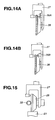
- the forming roller 26 After the positioning of the forming roller 26, the forming roller 26 is pressed against the workpiece 21 at a predetermined load as shown in FIG. 15 upon movement of the housing 29 in the Y-axis direction. At this time, the recess 3 can be machined to a desired depth by previously calculating the load for machining the recess 3 and controlling the load based on the calculation result.
- each adjacent recesses 3 (for example, the recess 3A in FIG. 16 ) is formed in the outer peripheral surface of the workpiece 21 by moving the forming roller 26 in the X-axis direction every after one rotation of the forming roller 26 or by moving the forming roller 26 in the X-axis direction over the whole of the machining area of the outer peripheral surface of the workpiece 21 while rotating the forming roller 26.
- plastic machining it is possible to form the recesses 3 at a low cost in a short time while controlling the cross-section profile of the recesses 3.
- the forming roller drive unit 31 is rotated with no load.
- the forming roller 26 Upon completion of the movement of the forming roller 26 in the X-axis direction, the forming roller 26 is detached from the workpiece 21 by upward movement of the housing 29 in the Y-axis direction.
- the rotational position of the forming roller 26 is detected by the forming roller detection measurement unit 30.
- the forming roller drive unit 33 and the forming roller positioning unit 34 the forming roller 26 is rotated to and locked in such position that the protrusion 25 on the outer peripheral surface of the forming roller 26 is pushed perpendicularly into the workpiece 21.
- the rotational angle of the forming roller 26 is detected by the forming roller detection measurement unit 30 and the signal of the detected rotational angle is inputted into the control unit 38.
- the control unit 38 calculates the rotational angle of the workpiece 21 at which the other of the adjacent recesses 3 (the recess 3B in FIG. 16 ) can be formed at a machining interval ⁇ from the precedingly formed recess 3 (the recess 3A in FIG. 16 ), and then, causes rotation of the workpiece 21.
- a machining shape measurement unit 36 such as a laser measurement means or CCD camera may be provided on the arm 27 to observe the outer peripheral surface of the workpiece 21.
- the machining shape measurement unit 36 When the machining shape measurement unit 36 is provided, the workpiece 21 is rotated by measuring the position of the precedingly machined recess 3A during one rotation of the workpiece 21 and calculating the rotational angle of the workpiece 21 such that the machining position of the recess 3B becomes located at the machining interval ⁇ from this measured position. It is thus possible to control the machining interval ⁇ between the adjacent recesses 3 with high precision even when the actual machining position differs from the originally intended machining position as shown in FIG. 18 .
- the forming roller 26 is pressed against the workpiece 21 at a predetermined load.
- the adjacent recesses 3B are then precisely formed in the outer peripheral surface of the workpiece 21 at the interval ⁇ from the precedingly formed recesses 3A by moving the forming roller 26 together with the housing 29 in the X-axis direction while rotating the workpiece 21 in the same manner as mentioned above after contraction of the forming roller positioning unit 34.
- Three or more recesses 3A can be formed in each texture group 4 by repeating the same machining operations as above.
- the workpiece 21' is once deformed into a shape indicated by a double-dashed line and then machined into a shape indicated by a dashed line when the forming roller protrusions 25', 25" are pressed against the workpiece 21' to form the recesses 3', 3" as indicated by a solid line in FIGS. 23A and 23B .
- the part 37', 37" between the adjacent recesses 3 of the workpiece 21' (corresponding to the part between the protrusions 25', 25") cannot be thus formed into a desired shape by close location of the protrusions 25', 25".
- the adjacent recesses 3 (3A, 3B) are formed separately and serially. It is thus possible to reduce the effect of material plastic flow and machine the adjacent recesses 3 to a more desired shape with a high degree of precision.
- a sliding member production apparatus 40 according to another embodiment of the present invention will be next described below.
- the production apparatus 40 of the present embodiment includes another set of forming roller 26, arm 27, forming roller detection measurement unit 30, load application unit 31, load measurement unit 32 and housing 29 in addition to the production apparatus 20 of the above-described embodiment.
- the adjacent recesses 3A and 3B are formed in the outer peripheral surface of the workpiece 21 by simultaneously pressing two forming rollers 26 against the workpiece 21 and moving the forming rollers 26 in the axial direction of the workpiece 21. Namely, the press positions of these two forming rollers 26 against the workpiece 21 are controlled to the machining positions of the recesses 3A and 3B. It is thus possible to machine the adjacent recesses 3A and 3B to a desired shape with a high degree of precision by forming the recesses 3A (or the recesses 3B) and then, after the effect of material plastic flow ceases, forming the recesses 3B (or the recesses 3A) through the use of the separate forming rollers 26 of the production apparatus 40. It is also possible to perform the recess machining operations in a short time by the plurality of forming rollers 26.
- the movements of two forming rollers 26 in the axial direction of the workpiece 21 can be made in the same direction from the same end as shown in FIGS. 19A and 19B , or can be made in the opposite directions from the opposite ends as shown in FIG. 20 .
- the adjacent fine recesses 3 can be formed in different shapes by varying the shapes of the protrusions 25 on the outer peripheral surfaces of two forming rollers 26, respectively.
- the production apparatus 50 of the present embodiment is substantially similar in structure to the production apparatus 40 of the above-described embodiment, except that one of two forming rollers 26 used in the subsequent machining operation to form the recesses 3B (or recesses 3A) among the adjacent recesses 3A and 3B includes a positioning protrusion(s) 51 adjacent to the protrusion(s) 25 on the outer peripheral surface thereof.
- the protrusion 25 and the positioning protrusion 51 are located corresponding to the positional relationship of two adjacent recesses 3A and 3B.
- the positioning protrusion 51 is shaped like the protrusion 25 of the forming roller 26 used in the preceding machining operation so as to fit in the precedingly machined recess 3A (or recesses 3B).
- the positioning protrusion 51 has a curved surface in spherical form or arc form as shown in FIG. 22 , it is further possible to reduce the effect on the shape of the precedingly machined recesses 3A (or recesses 3B) and increase the tool life of the forming roller 26.
- the production apparatus 40, 50 may have three or more forming roller 26 when the low-friction sliding member 1 has three or more recesses 3 in each texture group 4.
Landscapes
- Engineering & Computer Science (AREA)
- General Engineering & Computer Science (AREA)
- Mechanical Engineering (AREA)
- Chemical & Material Sciences (AREA)
- Oil, Petroleum & Natural Gas (AREA)
- Combustion & Propulsion (AREA)
- Sliding-Contact Bearings (AREA)
- Pistons, Piston Rings, And Cylinders (AREA)
Claims (15)
- Reibungsarmes Gleitelement (1) mit einer Gleitfläche (2), dass bezüglich eines gegenüberliegenden Elements über Öl gleitfähig ist, wobei die Gleitfläche (2) eine Mehrzahl von Strukturgruppen (4) aufweist, wobei jede der Strukturgruppen (4) aus zumindest zwei benachbarten dünnen Aussparungen mit Bereichen besteht, die entweder in Gleitrichtung oder Ölflussrichtung zueinander ausgerichtet sind, wobei das reibungsarme Gleitelement (1) dadurch gekennzeichnet ist, dass ein Abstand zwischen zwei benachbarten Gruppen der Strukturgruppen (4) in Gleitrichtung oder Ölflussrichtung größer als ein Abstand zwischen den benachbarten Aussparungen (3) der Strukturgruppen (4) in Gleitrichtung oder Ölflussrichtung ist; und wobei die Strukturgruppen (4) einheitlich über die Gleitfläche (2) verteilt sind.
- Reibungsarmes Gleitelement gemäß Anspruch 1, wobei das Verhältnis eines Abstandes (X) zwischen den Aussparungen (3) in Gleitrichtung zu einer Länge (L) der Aussparungen in Gleitrichtung von 0,25 bis 5 reicht.
- Reibungsarmes Gleitelement gemäß Anspruch 1, wobei der Flächenanteil der Aussparungen (3) in der Gleitfläche von 0,5 bis 10% reicht.
- Reibungsarmes Gleitelement gemäß Anspruch 1, wobei die Aussparungen (3) ein Verhältnis h/D von 0,04 bis 5 erfüllen, wobei h eine Tiefe der Aussparungen (3) und D eine viskose Flüssigkeitsdicke auf der Gleitfläche (2) während des Gleitens ist.
- Reibungsarmes Gleitelement gemäß Anspruch 1, wobei die Aussparungen (3) in eine Richtung senkrecht zur Gleitrichtung oder Ölflussrichtung verlängert sind.
- Reibungsarmes Gleitelement gemäß Anspruch 1, wobei die Aussparungen (3) eine kürzere Länge von 50 bis 150 µm und eine größere Länge, die zwei bis zehn mal länger als die kürzere Länge der Aussparungen (3) ist, aufweisen.
- Herstellungsvorrichtung (20) eines reibungsarmen Gleitelements (1), wobei das Gleitelement (1) eine Gleitfläche (2) aufweist, die mit einer Mehrzahl von Strukturgruppen (4) ausgebildet ist, wobei jede der Strukturgruppen (4) aus zumindest zwei benachbarten Aussparungen (3) besteht, wobei die Herstellungsvorrichtung aufweist:- eine Werkstückträgereinheit (22), die ein zu bearbeitendes zylindrisches Werkstück (21) im Gleitelement (1) trägt, um somit eine Drehung des Werkstücks (21) und Positionierung des Werkstückes (21) in Drehrichtung zu ermöglichen;- eine zylindrische Formwalze (23) mit einer äußeren Umfangsfläche, die mit einer Mehrzahl von Vorsprüngen (25) ausgebildet ist;- eine Formwalzenträgereinheit (28), die die Formwalze (23) trägt, um somit eine Drehung der Formwalze (23) und eine relative axiale Bewegung der Formwalze (23) und des Werkstückes (21) zu ermöglichen;- eine Lastaufbringungseinheit (31), die die Formwalze (23) gegen das Werkstück (21) mit einer vorbestimmten Last drückt;- eine Formwalzenmesseinheit (30), die eine Drehposition der Formwalze (23) misst;- eine Formwalzenantriebseinheit (33), die die Drehposition der Formwalze (23) durch Drehung der Formwalze (23) einstellt;- eine Formwalzenpositioniereinheit (34), die die Drehung der Formwalze (23) stoppt und die Formwalze (23) in der Position verriegelt;- eine Steuerungseinheit (38), die die Bedienungssteuerung der Drehpositionen der Formwalze (23) und des Werkstückes (21) und die axiale Position der Formwalze (23) in der Weise ausführt, um die benachbarten Aussparungen (3) von jeder Strukturgruppe (4) seriell auszubilden, dadurch gekennzeichnet, dass ein Abstand zwischen zwei benachbarten Gruppen der Strukturgruppen (4) in Gleitrichtung oder Ölflussrichtung größer als ein Abstand zwischen den benachbarten Aussparungen (3) der Strukturgruppen (4) in Gleitrichtung oder Ölflussrichtung ist, und die Strukturgruppen (4) einheitlich über die Gleitfläche (2) verteilt sind.
- Herstellungsvorrichtung für das reibungsarme Gleitelement gemäß Anspruch 7, wobei die Formwalzenmesseinheit (30) mit einer Drehachse der Formwalze (23) verbunden ist, um so die Drehposition der Formwalze (23) zu messen.
- Herstellungsvorrichtung des reibungsarmen Gleitelements gemäß Anspruch 7, wobei die Formwalzenmesseinheit (30) die Drehposition der Formwalze (23) durch einen Laser misst.
- Herstellungsvorrichtung des reibungsarmen Gleitelements gemäß Anspruch 7, wobei die Formwalzenmesseinheit (30) die Drehposition der Formwalze (23) durch eine Bildgebungseinrichtung misst.
- Herstellungsvorrichtung des reibungsarmen Gleitelements gemäß Anspruch 7, die ferner aufweist: eine Bearbeitungsform-Messeinheit (36), die eine Position der Aussparung (3) misst, die im Werkstück (21) ausgebildet ist.
- Herstellungsvorrichtung des reibungsarmen Gleitelements gemäß Anspruch 7, die eine Mehrzahl von Formwalzen (23) aufweist, wobei jede äußere Umfangsflächen aufweist, die mit Vorsprüngen (25) ausgebildet sind.
- Herstellungsvorrichtung des reibungsarmen Gleitelements gemäß Anspruch 12, wobei die Vorsprünge (25) auf den äußeren Umfangsflächen der Formwalzen (23) in der Form variieren.
- Herstellungsvorrichtung des reibungsarmen Gleitelements gemäß Anspruch 12, wobei zumindest eine der Formwalzen (23) benachbarte Vorsprünge (25) aufweist, die gemäß den zu bearbeitenden benachbarten Aussparungen (3) ausgebildet sind; wobei einer der benachbarten Vorsprünge (25) als Positioniervorsprung (51) fungiert; und die Steuerungseinheit (38) die Betriebssteuerung in der Weise ausführt, um den Positioniervorsprung (51) in jeden der Vorsprünge (3) einzupassen, die durch jede der Formwalzen (23), mit Ausnahme zumindest einer der Formwalzen (23), ausgebildet wird.
- Herstellungsvorrichtung des reibungsarmen Gleitelements gemäß Anspruch 14, wobei der Positioniervorsprung (51) eine gebogene Fläche, entweder kugelförmig oder bogenförmig, aufweist.
Applications Claiming Priority (3)
| Application Number | Priority Date | Filing Date | Title |
|---|---|---|---|
| JP2006015522 | 2006-01-24 | ||
| JP2006236725A JP5228303B2 (ja) | 2006-01-24 | 2006-08-31 | 低摩擦摺動部材、その製造装置並びに製造方法 |
| PCT/JP2006/326006 WO2007086227A1 (ja) | 2006-01-24 | 2006-12-27 | 低摩擦摺動部材、その製造装置並びに製造方法 |
Publications (3)
| Publication Number | Publication Date |
|---|---|
| EP1978286A1 EP1978286A1 (de) | 2008-10-08 |
| EP1978286A4 EP1978286A4 (de) | 2012-02-15 |
| EP1978286B1 true EP1978286B1 (de) | 2013-04-17 |
Family
ID=38309028
Family Applications (1)
| Application Number | Title | Priority Date | Filing Date |
|---|---|---|---|
| EP06843388.7A Ceased EP1978286B1 (de) | 2006-01-24 | 2006-12-27 | Reibungsarmes schiebeglied, herstellungsvorrichtung dafür und verfahren zu dessen herstellung |
Country Status (4)
| Country | Link |
|---|---|
| US (1) | US8202004B2 (de) |
| EP (1) | EP1978286B1 (de) |
| JP (1) | JP5228303B2 (de) |
| WO (1) | WO2007086227A1 (de) |
Families Citing this family (14)
| Publication number | Priority date | Publication date | Assignee | Title |
|---|---|---|---|---|
| JP5322020B2 (ja) * | 2008-02-25 | 2013-10-23 | 日産自動車株式会社 | 微細凹部の加工装置 |
| US9551421B2 (en) * | 2009-02-10 | 2017-01-24 | Nok Corporation | Sliding member and process for producing the same |
| BRPI0902385A2 (pt) * | 2009-07-15 | 2011-03-09 | Mahle Metal Leve Sa | segmento e bronzina de mancal para motores de combustão interna de veìculos |
| GB2483475B (en) * | 2010-09-08 | 2015-08-05 | Dormer Tools Ltd | Bore cutting tool and method of making the same |
| KR101843196B1 (ko) * | 2010-11-18 | 2018-03-29 | 두산인프라코어 주식회사 | 내마모성이 개선된 로커암 샤프트 및 이를 포함하는 로커암 샤프트-부시 조립체 |
| JP5842169B2 (ja) * | 2011-06-15 | 2016-01-13 | パナソニックIpマネジメント株式会社 | 摺動部材及び圧縮機 |
| DE102012217181A1 (de) | 2012-09-24 | 2014-03-27 | Federal-Mogul Nürnberg GmbH | Kolbenbolzen mit strukturierter Oberfläche und Verfahren zu dessen Herstellung |
| JP6051790B2 (ja) * | 2012-11-06 | 2016-12-27 | スズキ株式会社 | 内燃機関のピストン |
| DE102014003149A1 (de) * | 2014-03-04 | 2015-09-10 | Federal-Mogul Burscheid Gmbh | Ölabstreifkolbenring und Verfahren zur Herstellung eines Ölabstreifkolbenrings |
| DE102017125137A1 (de) * | 2017-10-26 | 2019-05-02 | Man Diesel & Turbo Se | Lagerbuchse eines Turboladers und Turbolader |
| DE102019219445A1 (de) * | 2019-12-12 | 2021-06-17 | Federal-Mogul Nürnberg GmbH | Kolben und Verfahren zur Herstellung desselben |
| CN111112335B (zh) * | 2019-12-19 | 2024-09-27 | 山东泰东环保科技股份有限公司 | 一种轧钢立钢器 |
| KR102345322B1 (ko) * | 2020-08-11 | 2021-12-31 | 엘지전자 주식회사 | 리니어 압축기 |
| JP7658884B2 (ja) * | 2021-11-29 | 2025-04-08 | トヨタ自動車株式会社 | 弁構造体 |
Family Cites Families (21)
| Publication number | Priority date | Publication date | Assignee | Title |
|---|---|---|---|---|
| US1016561A (en) * | 1909-06-02 | 1912-02-06 | Peter Grabler | Plunger and cylinder packing. |
| US2673767A (en) * | 1950-08-16 | 1954-03-30 | Harnischfeger Corp | Sleeve bearing |
| DE1450034A1 (de) * | 1964-05-02 | 1969-09-04 | Schmidt Gmbh Karl | Gleitlager mit Schmiermittelnuten |
| JPS61268848A (ja) | 1985-05-22 | 1986-11-28 | Mitsubishi Heavy Ind Ltd | シリンダの製造方法 |
| US4987865A (en) * | 1989-10-11 | 1991-01-29 | Wickes Manufacturing Company | Reduced friction piston |
| JPH07133704A (ja) * | 1993-11-08 | 1995-05-23 | Nissan Motor Co Ltd | カムシャフトおよびその製造方法 |
| EP0877866B2 (de) * | 1996-01-30 | 2004-09-01 | Federal-Mogul Wiesbaden GmbH & Co.KG | Gleitlagerelement mit schmieröltaschen |
| JP2000346045A (ja) * | 1999-06-01 | 2000-12-12 | Daido Metal Co Ltd | エンジン用主軸受 |
| JP2001099158A (ja) | 1999-09-29 | 2001-04-10 | Daido Metal Co Ltd | すべり軸受 |
| JP3712052B2 (ja) * | 2001-02-09 | 2005-11-02 | 日産自動車株式会社 | 低摩擦摺動部材 |
| JP3994750B2 (ja) * | 2001-05-14 | 2007-10-24 | 株式会社ジェイテクト | 密封装置 |
| DE10249818B4 (de) * | 2002-10-24 | 2005-10-20 | Daimler Chrysler Ag | Oberfläche eines Körpers, auf dem ein anderer Körper in einer bevorzugten Gleitrichtung gegeneinander gleitend anordenbar ist |
| JP2004340248A (ja) * | 2003-05-15 | 2004-12-02 | Daido Metal Co Ltd | 摺動部材 |
| JP4973971B2 (ja) * | 2003-08-08 | 2012-07-11 | 日産自動車株式会社 | 摺動部材 |
| US7270482B2 (en) * | 2004-02-05 | 2007-09-18 | Nissan Motor Co., Ltd. | Sliding device |
| JP4655609B2 (ja) * | 2004-02-05 | 2011-03-23 | 日産自動車株式会社 | 摺動部材 |
| JP4697393B2 (ja) | 2004-04-28 | 2011-06-08 | 日産自動車株式会社 | 円形穴の加工装置及び加工方法 |
| US7328637B2 (en) * | 2004-04-28 | 2008-02-12 | Nissan Motor Co., Ltd. | Apparatus for machining a cylinder bore surface and method of machining the cylinder bore surface using the apparatus |
| JP2005320934A (ja) | 2004-05-11 | 2005-11-17 | Toyo Drilube Co Ltd | 往復運動部材 |
| JP2006017259A (ja) | 2004-07-02 | 2006-01-19 | Nissan Motor Co Ltd | 摺動装置 |
| JP2006161563A (ja) | 2004-12-02 | 2006-06-22 | Honda Motor Co Ltd | 内燃機関のピストン |
-
2006
- 2006-08-31 JP JP2006236725A patent/JP5228303B2/ja active Active
- 2006-12-27 WO PCT/JP2006/326006 patent/WO2007086227A1/ja not_active Ceased
- 2006-12-27 EP EP06843388.7A patent/EP1978286B1/de not_active Ceased
- 2006-12-27 US US12/161,063 patent/US8202004B2/en not_active Expired - Fee Related
Also Published As
| Publication number | Publication date |
|---|---|
| US20100150482A1 (en) | 2010-06-17 |
| EP1978286A1 (de) | 2008-10-08 |
| US8202004B2 (en) | 2012-06-19 |
| JP5228303B2 (ja) | 2013-07-03 |
| JP2007225105A (ja) | 2007-09-06 |
| EP1978286A4 (de) | 2012-02-15 |
| WO2007086227A1 (ja) | 2007-08-02 |
Similar Documents
| Publication | Publication Date | Title |
|---|---|---|
| EP1978286B1 (de) | Reibungsarmes schiebeglied, herstellungsvorrichtung dafür und verfahren zu dessen herstellung | |
| CN114206520B (zh) | 具有弹性工具加工的增量式板材成形系统 | |
| JP2628824B2 (ja) | 内蔵中心線調節機構を有する固定振れ止め | |
| US20090126440A1 (en) | Device and method for producing profiled bodies | |
| JP2010535107A (ja) | クランクシャフトを強化するための方法及び装置 | |
| EP1587649B1 (de) | vorrichtung zur hochgenauen bearbeitung der oberfläche eines objektes, insbesondere zum polieren und läppen von halbleitersubstraten | |
| US10371178B2 (en) | Hydraulic actuator device | |
| KR100613916B1 (ko) | 리니어 가이드의 레일용 소재, 리니어 가이드용 레일,리니어 가이드의 레일 제조 방법 및 리니어 가이드 | |
| CN102689319B (zh) | 用于金属板加工机的工具和切割薄膜的方法 | |
| JP3629948B2 (ja) | 金属板の逐次張出し成形方法およびその装置ならびに成形品 | |
| KR100538897B1 (ko) | 재료를제거하지않고박판을기계가공하는방법및장치 | |
| JP4235734B2 (ja) | ハイブリッド型直動案内装置 | |
| JP2006150440A (ja) | 微細凹部の加工装置及び加工方法 | |
| Szurdak et al. | Development and experimental verification of a new roller-coining setup to texture flat and curved surfaces | |
| CN217167291U (zh) | 一种滚压工具 | |
| JP3989324B2 (ja) | 変位量微調整装置 | |
| Hiegemann et al. | Control of the material flow in deep drawing by the use of rolled surface textures | |
| KR102412261B1 (ko) | 베벨타입 스냅링 제조방법 및 제조장치 | |
| JP2007187190A (ja) | シンクロナイザリング | |
| JP4356919B2 (ja) | 表面ブローチ加工方法及び表面ブローチ加工治具 | |
| JP2025044745A (ja) | 転がり疲労強度試験装置 | |
| HK40062148A (en) | Incremental sheet forming system with resilient tooling | |
| HK40062148B (zh) | 具有弹性工具加工的增量式板材成形系统 | |
| CN121061540A (zh) | 一种孔轴装配装置 | |
| JP2022148521A (ja) | 管内面の切削加工工具 |
Legal Events
| Date | Code | Title | Description |
|---|---|---|---|
| PUAI | Public reference made under article 153(3) epc to a published international application that has entered the european phase |
Free format text: ORIGINAL CODE: 0009012 |
|
| 17P | Request for examination filed |
Effective date: 20080701 |
|
| AK | Designated contracting states |
Kind code of ref document: A1 Designated state(s): DE FR GB |
|
| DAX | Request for extension of the european patent (deleted) | ||
| RBV | Designated contracting states (corrected) |
Designated state(s): DE FR GB |
|
| A4 | Supplementary search report drawn up and despatched |
Effective date: 20120118 |
|
| RIC1 | Information provided on ipc code assigned before grant |
Ipc: F02F 3/00 20060101ALI20120112BHEP Ipc: F16C 33/10 20060101ALI20120112BHEP Ipc: F02F 5/00 20060101ALI20120112BHEP Ipc: F16J 1/08 20060101AFI20120112BHEP Ipc: F16J 10/04 20060101ALI20120112BHEP Ipc: F16C 33/14 20060101ALI20120112BHEP |
|
| 17Q | First examination report despatched |
Effective date: 20120822 |
|
| GRAP | Despatch of communication of intention to grant a patent |
Free format text: ORIGINAL CODE: EPIDOSNIGR1 |
|
| GRAS | Grant fee paid |
Free format text: ORIGINAL CODE: EPIDOSNIGR3 |
|
| GRAA | (expected) grant |
Free format text: ORIGINAL CODE: 0009210 |
|
| AK | Designated contracting states |
Kind code of ref document: B1 Designated state(s): DE FR GB |
|
| REG | Reference to a national code |
Ref country code: GB Ref legal event code: FG4D |
|
| REG | Reference to a national code |
Ref country code: DE Ref legal event code: R096 Ref document number: 602006035785 Country of ref document: DE Effective date: 20130613 |
|
| PLBE | No opposition filed within time limit |
Free format text: ORIGINAL CODE: 0009261 |
|
| STAA | Information on the status of an ep patent application or granted ep patent |
Free format text: STATUS: NO OPPOSITION FILED WITHIN TIME LIMIT |
|
| 26N | No opposition filed |
Effective date: 20140120 |
|
| REG | Reference to a national code |
Ref country code: DE Ref legal event code: R097 Ref document number: 602006035785 Country of ref document: DE Effective date: 20140120 |
|
| REG | Reference to a national code |
Ref country code: FR Ref legal event code: PLFP Year of fee payment: 10 |
|
| REG | Reference to a national code |
Ref country code: FR Ref legal event code: PLFP Year of fee payment: 11 |
|
| REG | Reference to a national code |
Ref country code: FR Ref legal event code: PLFP Year of fee payment: 12 |
|
| PGFP | Annual fee paid to national office [announced via postgrant information from national office to epo] |
Ref country code: DE Payment date: 20181211 Year of fee payment: 13 |
|
| PGFP | Annual fee paid to national office [announced via postgrant information from national office to epo] |
Ref country code: GB Payment date: 20181227 Year of fee payment: 13 Ref country code: FR Payment date: 20181120 Year of fee payment: 13 |
|
| REG | Reference to a national code |
Ref country code: DE Ref legal event code: R119 Ref document number: 602006035785 Country of ref document: DE |
|
| GBPC | Gb: european patent ceased through non-payment of renewal fee |
Effective date: 20191227 |
|
| PG25 | Lapsed in a contracting state [announced via postgrant information from national office to epo] |
Ref country code: GB Free format text: LAPSE BECAUSE OF NON-PAYMENT OF DUE FEES Effective date: 20191227 Ref country code: FR Free format text: LAPSE BECAUSE OF NON-PAYMENT OF DUE FEES Effective date: 20191231 Ref country code: DE Free format text: LAPSE BECAUSE OF NON-PAYMENT OF DUE FEES Effective date: 20200701 |