EP1976033A2 - Procédé de fabrication de film conducteur transparent et procédé de fabrication du composant d'un dispositif électroluminescent à semi-conducteur - Google Patents
Procédé de fabrication de film conducteur transparent et procédé de fabrication du composant d'un dispositif électroluminescent à semi-conducteur Download PDFInfo
- Publication number
- EP1976033A2 EP1976033A2 EP08010616A EP08010616A EP1976033A2 EP 1976033 A2 EP1976033 A2 EP 1976033A2 EP 08010616 A EP08010616 A EP 08010616A EP 08010616 A EP08010616 A EP 08010616A EP 1976033 A2 EP1976033 A2 EP 1976033A2
- Authority
- EP
- European Patent Office
- Prior art keywords
- film
- transparent conductor
- emitting device
- manufacturing
- conductor film
- Prior art date
- Legal status (The legal status is an assumption and is not a legal conclusion. Google has not performed a legal analysis and makes no representation as to the accuracy of the status listed.)
- Withdrawn
Links
Images


Classifications
-
- E—FIXED CONSTRUCTIONS
- E05—LOCKS; KEYS; WINDOW OR DOOR FITTINGS; SAFES
- E05B—LOCKS; ACCESSORIES THEREFOR; HANDCUFFS
- E05B63/00—Locks or fastenings with special structural characteristics
- E05B63/22—Locks or fastenings with special structural characteristics operated by a pulling or pushing action perpendicular to the front plate, i.e. by pulling or pushing the wing itself
-
- H—ELECTRICITY
- H01—ELECTRIC ELEMENTS
- H01L—SEMICONDUCTOR DEVICES NOT COVERED BY CLASS H10
- H01L33/00—Semiconductor devices with at least one potential-jump barrier or surface barrier specially adapted for light emission; Processes or apparatus specially adapted for the manufacture or treatment thereof or of parts thereof; Details thereof
- H01L33/36—Semiconductor devices with at least one potential-jump barrier or surface barrier specially adapted for light emission; Processes or apparatus specially adapted for the manufacture or treatment thereof or of parts thereof; Details thereof characterised by the electrodes
- H01L33/40—Materials therefor
- H01L33/42—Transparent materials
-
- E—FIXED CONSTRUCTIONS
- E05—LOCKS; KEYS; WINDOW OR DOOR FITTINGS; SAFES
- E05B—LOCKS; ACCESSORIES THEREFOR; HANDCUFFS
- E05B1/00—Knobs or handles for wings; Knobs, handles, or press buttons for locks or latches on wings
- E05B1/0053—Handles or handle attachments facilitating operation, e.g. by children or burdened persons
-
- Y—GENERAL TAGGING OF NEW TECHNOLOGICAL DEVELOPMENTS; GENERAL TAGGING OF CROSS-SECTIONAL TECHNOLOGIES SPANNING OVER SEVERAL SECTIONS OF THE IPC; TECHNICAL SUBJECTS COVERED BY FORMER USPC CROSS-REFERENCE ART COLLECTIONS [XRACs] AND DIGESTS
- Y10—TECHNICAL SUBJECTS COVERED BY FORMER USPC
- Y10S—TECHNICAL SUBJECTS COVERED BY FORMER USPC CROSS-REFERENCE ART COLLECTIONS [XRACs] AND DIGESTS
- Y10S438/00—Semiconductor device manufacturing: process
- Y10S438/94—Laser ablative material removal
Definitions
- the present invention generally relates to a semiconductor light-emitting device, and more specifically, it relates to a semiconductor light-emitting device so improved that a large quantity of light is extractable.
- the present invention also relates to a method of manufacturing a transparent conductor film, and more specifically, it relates to a method of manufacturing a transparent conductor film improved to be smooth at a lower temperature and have low resistance and high transmittance so that the cost can be reduced.
- the present invention further relates to a method of manufacturing a compound semiconductor light-emitting device employing such a method.
- Figs. 9A and 9B illustrate the structure of a conventional light-emitting device and the light-emitting mechanism thereof.
- a light-emitting diode LED
- a light-emitting diode is an electrical/optical conversion type semiconductor light emitting device utilizing minority carrier injection in a p-n junction part formed by p- and n-type semiconductor crystals adjacent to each other and subsequent recombination radiation.
- the device itself is made of a semiconductor crystal material of about 0.3 mm square, and the basic structure thereof is similar to that of an Si rectifying device, as shown in Fig. 9A .
- Such an LED has durability, long-livedness, a light weight and a miniature size.
- the LED which has been applied only to an indoor indicator lamp, is now applied to the stop lamp of a car, a road sign, a traffic light, a large-area color display or the like following improvement of efficiency and brightness and reduction of the price.
- Luminous efficiency of an LED includes external quantum efficiency and internal quantum efficiency, and the efficiency of the LED is proportional to the product thereof.
- the internal quantum efficiency is expressed in the ratio of the number of generated photons to the number of injected electron-hole pairs. In order to improve the internal quantum efficiency, it is necessary to obtain a high-quality crystal containing a small number of defects or impurities, in order to prevent recombination of the electron-hole pairs.
- the external quantum efficiency is expressed in the ratio of the number of photons radiated outward to the number of the injected electron-hole pairs.
- Light generated from an active layer is absorbed by the active layer itself, a substrate or an electrode, and hence can be only partially extracted into air.
- the refractive index of the semiconductor is by far higher than that of the outside and hence most part of the light is totally reflected by the boundary between the semiconductor and the outside and returned into the semiconductor.
- Most of LEDs now on the market are sealed with epoxy resin having a refractive index of 1.5, in order to increase the critical angle of total reflection for extracting a larger quantity of light, in addition to the purposes of protection and antioxidation of the LEDs.
- Fig. 10 is a conceptual diagram showing the structure of a conventional LED.
- An active layer 23 is formed on an n-type semiconductor layer 22 having an n electrode 21 on the back surface.
- a p-type semiconductor layer 24 is formed on the active layer 23.
- a p electrode 25 is formed on the p-type semiconductor layer 24. Recombination radiation occurs at the maximum immediately under an electrode in which a current flows at the maximum.
- a general electrode blocks light, and hence it follows that light emitted immediately under the electrode is hardly extracted outward. In this case, it is important to spread the current to a region other than the electrode. Therefore, a current diffusion layer is provided or a thin gold electrode transmitting light is provided on the overall surface.
- Fig. 11 is a sectional view of an LED having a current diffusion electrode 26 provided on a p-type semiconductor layer 24.
- the current diffusion electrode 26 is formed by an Au thin film of about 20 nm in thickness, in order to obtain sufficient current spreading.
- the transmittance of the Au thin film 26 having this thickness is only 37 % for light of 500 nm in wavelength. Thus, most part of the light is absorbed, to result in inferior luminous efficiency.
- the transparent conductor film applied to the conventional compound semiconductor light-emitting device is generally prepared from ITO (In 2 O 3 -5 wt.% SnO 2 ). Sputtering is mainly employed for forming a film of ITO having transmittance of at least 80 % and resistivity of about 2 x 10 -4 ⁇ cm at a substrate temperature of 300°C with excellent reproducibility.
- ITO In 2 O 3 -5 wt.% SnO 2
- Sputtering is mainly employed for forming a film of ITO having transmittance of at least 80 % and resistivity of about 2 x 10 -4 ⁇ cm at a substrate temperature of 300°C with excellent reproducibility.
- EL organic electroluminescence
- LED light-emitting diode
- Japanese Patent Laying-Open No. 6-318406 (1994 ) proposes a technique of manufacturing a film of In 2 O 3 -10 wt.% ZnO capable of implementing high transmittance and low resistivity at the room temperature.
- a film of 140 nm in thickness formed by sputtering under the room temperature implements resistivity of 3 x 10 -4 ⁇ cm and transmittance of 86 % (at 550 nm).
- the transmittance and conductivity of a transparent conductor film remarkably depend on the amount of oxygen.
- the film forming pressure is disadvantageously limited due to running of a vapor deposition source.
- the pressure and the gas for forming a film are limited such that the pressure range is limited for utilizing plasma and argon is required for forming the plasma, and hence the amount of oxygen cannot be precisely controlled.
- the present invention has been proposed in order to solve the aforementioned problems, and an object thereof is to provide a semiconductor light-emitting device improved to be capable of increasing luminous efficiency.
- Another object of the present invention is to provide a method of manufacturing a transparent conductor film improved to be capable of precisely controlling the amount of oxygen with no limitation of the film forming pressure and the film forming gas.
- Still another object of the present invention is to provide a method of manufacturing a transparent conductor film improved to be capable of improving transmittance and reducing the cost.
- a further object of the present invention is to provide a method of manufacturing a compound semiconductor light-emitting device including a step of forming a transparent conductor film improved to be capable of improving transmittance and reducing the cost.
- a semiconductor light-emitting device comprises a substrate provided with an n-type lower electrode on the back surface.
- a light-emitting layer is provided on the aforementioned substrate.
- a p-type semiconductor layer is provided on the aforementioned light-emitting layer.
- An upper electrode is provided on the aforementioned p-type semiconductor layer.
- the aforementioned upper electrode has a multilayer structure consisting of at least two heterogeneous layers.
- the upper electrode is formed by the multilayer structure consisting of at least two heterogeneous layers, whereby an upper electrode forming no junction with the p-type semiconductor layer and having high transmittance can be formed by properly selecting the heterogeneous layers.
- a semiconductor light-emitting diode having high luminous efficiency can be obtained.
- the aforementioned upper electrode includes an Au thin film coming into contact with the aforementioned p-type semiconductor layer and an n-type transparent conductor film formed thereon.
- the transparent conductor film generally prepared from an n-type semiconductor, inevitably forms a junction when the same is directly formed on the p-type semiconductor layer.
- an extremely thin Au film is formed on the p-type semiconductor layer, and the transparent conductor film is thereafter stacked thereon.
- the transmittance is not remarkably reduced.
- the transparent conductor film having high transmittance can be formed in a relatively large thickness. Consequently, a current effectively spreads over the electrode through the transparent conductor film.
- the thickness of the aforementioned Au thin film is 1nm to 3 nm.
- the thickness of the Au film is so sufficiently small that the transmittance is not remarkably reduced.
- the aforementioned transparent conductor film is made of In 2 O 3 -10 wt.% ZnO.
- the transmittance is increased when preparing the transparent conductor film from such a material.
- the aforementioned upper electrode has a multilayer structure including an upper layer and a lower layer.
- the surface of the aforementioned lower layer is flattened.
- the surface of the aforementioned upper layer is irregularized.
- light which is unextractable due to total reflection when the surface is smooth, can be effectively extracted outward by irregularly controlling the surface shape of the transparent conductor film. Consequently, optical output can be improved.
- the aforementioned substrate includes a ZnSe single-crystalline substrate.
- the aforementioned p-type semiconductor layer includes a ZnSe semiconductor layer, a ZnTe semiconductor layer or a BeTe semiconductor layer.
- the aforementioned transparent conductor film of In 2 O 3 -10 wt.% ZnO is formed by laser ablation.
- a substrate is first placed in a vacuum chamber.
- a target serving as the material for a transparent conductor film is centered in the aforementioned vacuum chamber.
- Oxygen is introduced into the aforementioned vacuum chamber.
- the aforementioned target is irradiated with a laser beam, for depositing atoms or molecular ions emitted by ablation on the aforementioned substrate and crystal-growing the atoms or molecular ions while oxidizing the same.
- This method referred to as laser ablation, is employed for forming a transparent conductor film in the present invention.
- an excimer laser beam serving as an excitation source is guided from outside a film forming apparatus, not to limit the film forming pressure and the film forming gas.
- the laser ablation involves no influence by reverse sputtering caused by negative ions, dissimilarly to sputtering.
- the amount of oxygen can be readily controlled and a film having a composition close to that of the target can be obtained due to the aforementioned characteristics. Further, it is possible to obtain a film having superior surface smoothness as compared with that formed by sputtering.
- In 2 O 3 -10 wt.% ZnO is employed for the aforementioned target.
- a method of manufacturing a transparent conductor film according to a tenth aspect of the present invention is carried out at a film forming temperature in the range of the room temperature (RT) to 300°C.
- a method of manufacturing a transparent conductor film according to an eleventh aspect of the present invention is carried out at a film forming pressure of 0.3 to 3 x 10 -3 Torr.
- a compound semiconductor light-emitting device substrate immediately before formation of a transparent electrode is first prepared.
- the aforementioned compound semiconductor light-emitting device substrate is placed in a vacuum chamber.
- a target serving as the material for a transparent conductor film is centered in the aforementioned vacuum chamber.
- Oxygen is introduced into the aforementioned vacuum chamber.
- the aforementioned target is irradiated with a laser beam, for crystal-growing the aforementioned transparent electrode while depositing atoms or molecular ions emitted by ablation on the aforementioned substrate and oxidizing the same.
- the transparent electrode is formed on the compound semiconductor light-emitting device substrate by laser ablation, whereby a compound semiconductor light-emitting device having low resistance and improved transmittance is obtained.
- In 2 O 3 -10 wt.% ZnO is employed as the aforementioned target.
- a method of manufacturing a compound semiconductor light-emitting device according to a fourteenth aspect of the present invention is carried out at a film forming temperature in the range of the room temperature (RT) to 300°C.
- a method of manufacturing a compound semiconductor light-emitting device according to a fifteenth aspect of the present invention is carried out at a film forming pressure of 0.3 to 3 x 10 -3 Torr.
- a transparent conductor film having low resistance and high transmittance is employed in place of a conventional Au film.
- the transparent conductor film is applied as a p-type electrode in the first embodiment of the present invention in particular.
- a transparent conductor film 30 generally consists of an n-type semiconductor, and inevitably forms a junction when directly formed on a p-type semiconductor layer 24.
- transmittance as well as luminous efficiency are reduced when an Au film 26 is formed on a p-type semiconductor layer.
- an extremely thin Au thin film 10a is formed on a p-type semiconductor layer 24, and a transparent conductor film 10b is thereafter stacked according to the present invention.
- the Au thin film 10a has a sufficiently small thickness of 1 to 3 nm, so that the transmittance is not remarkably reduced.
- the transparent conductor film 10b having high transmittance can be formed in a relatively large thickness. Consequently, a current effectively spreads over an electrode through the transparent conductor film 10b.
- Fig. 2 is a sectional view of a ZnSe compound semiconductor light-emitting device to which the present invention is applied.
- a p-type ZnTe layer 8 of 60 nm in thickness is provided on the uppermost surface.
- An upper electrode 10 having a multilayer structure of an Au thin film 10a of 1 to 3 nm in thickness and a transparent conductor film 10b formed thereon is formed on such an epi-structure.
- a second embodiment of the present invention relates to a technique of extracting light, which is unextractable due to total reflection, by (e.g., irregularly) controlling the surface shape of a transparent conductor film.
- optical output can be improved.
- Fig. 3 illustrates the concept of this embodiment.
- the critical angle can be increased by preparing the surface of the transparent conductor film in the form of a lens or a saw. Thus, light unextractable due to total reflection can be extracted outward and optical output can be improved.
- the transmittance of an electrode is increased and optical output is improved when a p-type electrode is formed by a transparent conductor film and an Au film. Further, the life is increased under constant output due to the improvement of the optical output.
- the surface shape of the transparent conductor film can be controlled due to the high transmittance thereof. Consequently, the optical output can be improved.
- the thickness of the transparent conductor film can be increased due to the high transmittance, and the surface shape thereof can be readily controlled.
- an LED having an active layer of ZnCdSe was formed on an n-type ZnSe(100) substrate prepared by CVT (chemical vapor transport).
- a p-type electrode was set in a p-type ZnSe/ZnTe superlattice structure.
- An Au film of 3 nm in thickness was formed thereon by vacuum deposition, and a film of In 2 O 3 /10 wt.% ZnO (IDIXO) was thereafter formed by laser ablation under the following conditions:
- Table 1 shows the relation between electrode structures, voltages and optical output values (in energization at 20 mA).
- Table 1 Electrode Structure Voltage Optical Output 20nm Au 2.88V 1.31mW IDIXO(90nm) / Au(3nm) 2.84V 1.91mW IDIXO(180nm) / Au(3nm) 2.79V 2.19mW IDIXO(190nm) 3.39V 2.21mW
- the optical output was increased from 1.31 mW to 2.19 mW, i.e., by 1.67 times, as compared with the conventional sample having the electrode structure of Au (20 nm).
- the operating voltage remained substantially unchanged.
- the optical output was substantially identical to that of the sample having the electrode structure of IDIXO (180 nm)/Au (3 nm) while the operating voltage was increased.
- the film of Au (3 nm) suppressed formation of a junction.
- the operating voltage was 2.80 V, and the optical output was increased to 2.43 mW.
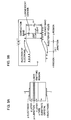
- Fig. 4 is a conceptual diagram of a laser ablation apparatus employed for a method of manufacturing a transparent conductor film according to the present invention.
- a method irradiating a solid surface with a high-density laser pulse, depositing ions or atoms emitted therefrom on a substrate located on an opposite position and forming a thin film is referred to as laser ablation.
- This method is remarkably suitable for a process of forming a metal oxide derivative thin film.
- laser ablation not only film formation but also refinement, etching, multi-layering etc. can be performed in the same experimental chamber with a strong laser pulse.
- laser ablation has the following advantages:
- a laser beam is introduced from outside a film forming chamber in this method, and hence a thin film can be formed in an arbitrary atmosphere pressure suitable for crystal growth. Further, atoms, molecules and ions are emitted only from a target, and hence a thin film containing no impurities is formed.
- Various parameters such as a pressure, a substrate temperature and a film forming rate can be individually selected.
- film formation can be instantaneously controlled by adjusting the number of laser pulses and energy.
- the film can be formed at an extremely high rate, as recently clarified.
- laser ablation has a number of excellent points.
- a bulk target consisting of a ferroelectric substance for forming a film is centered in a vacuum chamber, oxygen or gas such as ozone or NOz having strong oxidizing power is introduced into the vacuum system and the target is irradiated with a pulse laser beam for causing ablation. Atoms, molecules and ions emitted by ablation are deposited on the substrate and oxidized to cause crystal growth.
- a transparent conductor film was formed in such a laser ablation apparatus.
- Oxygen pressure dependency of the transmittance of the transparent conductor film was first investigated.
- a plume shape varies with the film forming pressure.
- the composition of a sample varies with the part of the plume on which the sample is located.
- the inventor has obtained such a result that the optimum target-to-substrate distance is about 60 to 70 mm in development of a superconducting device, and this time the target-to-substrate distance was fixed to 70 mm from observation of the plume, for evaluating the oxygen pressure dependency.
- the thickness of the IDIXO film was set to about 120 nm.
- Fig. 5 shows the relation between resistivity and oxygen pressure.
- the resistivity remarkably varied with the oxygen pressure, and a characteristic having a dip was obtained at 3 x 10 -3 Torr.
- the resistivity is lower by about one figure as compared with sputtering, and hence the necessary thickness can be reduced to 1/10, the transmittance can be increased and a high-quality transparent conductor film can be prepared at a low cost.
- the surface of the film prepared under these conditions was extremely smooth with roughness of about 0.5 nm. This value is about 1/10 that of a film prepared by sputtering.
- Fig. 6 shows results of evaluation of the oxygen pressure dependency of transmittance of IDIXO.
- An absorption edge of about 300 nm is recognized.
- the sample for measuring transmittance was formed by a substrate of MgO having an absorption edge of about 200 nm, and it is understood that absorption of 300 nm results from the IDIXO film.
- the transmittance of the MgO substrate measured at a wavelength of 500 nm was 84 %, and the relation between the film forming oxygen pressure and the transmittance of the IDIXO film (120 nm) can be calculated as shown in Table 3.
- an Au film having a small thickness is generally used as a transparent electrode.
- the transmittance of an Au film having a thickness of 20 nm is 37 %, and hence optical output exceeding twice that of a general light-emitting device can be obtained by employing an IDIXO film.
- Conceivable factors for such change of the resistivity are 1) change of the target composition and 2) change of the film thickness.
- the change 1) can be prevented by polishing the surface of the target and the change 2) can be prevented by setting a thickness monitor.
- the resistivity can be reduced by about one figure in best data as compared with the conventional sputtering. This shows such a possibility that the thickness of a transparent conductor film employed in general can be reduced to about 1/10.
- an excitation source heat in vapor deposition or plasma in sputtering
- an excimer laser beam serving as an excitation source is introduced from outside the apparatus in laser ablation, and hence the film forming pressure can be readily changed from a level close to the atmospheric pressure up to a high vacuum, to enable film formation under the optimum oxygen pressure.
- a film having a composition close to the target composition can be readily obtained in laser ablation. For such reasons, it is conceivable that formation of an IDIXO film having extremely high resistivity can be implemented according to the present invention.
- a transparent conductor film which consists of an n-type semiconductor in general, has a possibility of forming a junction when formed as a p electrode of a ZnSe LED.
- an IDIXO/Au structure obtained by forming an Au film before forming an IDIXO film was studied.
- Table 6 shows results in relation to resistivity.
- Fig. 7 shows transmittance in IDIXO/Au electrode structures. Reduction of transmittance resulting from the presence of Au is recognized. At a wavelength of 500 nm, the transmittance of the sample of IDIXO (120 nm)/Au (3 nm) is about 80 %. The transmittance was reduced as compared with the small thickness of the Au film conceivably because the transmittance of the IDIXO film itself was reduced due to the presence of Au.
- Fig. 8 is a sectional view of a compound semiconductor light-emitting device manufactured with application of the method of manufacturing a transparent conductor film according to the third embodiment of the present invention.
- an n electrode 52 is provided on the back surface of an n-type semiconductor layer 51.
- An active layer 53 is provided on the n-type semiconductor layer 51.
- a p-type semiconductor layer 54 is provided on the active layer 53.
- a contact layer 55 is provided on the p-type semiconductor layer 54.
- a p electrode 6, which is a transparent electrode, is provided on the contact layer 55.
- a pad 57 is provided on the p electrode 56. A current is fed to the pad 57 from an external power source (not shown) through a wire 58.
- a ZnSe LED preferably has an electrode structure of IDIXO (200 nm)/Au (3 nm), in order to maximize the optical output.
- the method of manufacturing a transparent conductor film having the aforementioned structure is not only applied to a method of forming a transparent electrode of a compound semiconductor light-emitting device but also employable in various fields of liquid crystal displays, solar batteries and the like.
- a semiconductor light-emitting device comprising: a substrate provided with an n-type lower electrode on the back surface; a light-emitting layer 4 provided on said substrate; a p-type semiconductor layer 24 provided on said light-emitting layer; and an upper electrode 10a, 10b provided on said p-type semiconductor layer, wherein said upper electrode has a multilayer structure consisting of at least two heterogeneous layers.
- the upper electrode includes an Au thin film 10a coming into contact with said p-type semiconductor layer 24 and an n-type transparent conductor film 10b formed on said Au thin film.
- the thickness of said Au thin film 10a is 1nm to 3 nm.
- said transparent conductor film (10b) is made of In 2 O 3 -10 wt.% ZnO.
- said upper electrode has a multilayer structure including an upper layer 10b and a lower layer 10a, the surface of said upper layer 10a is flattened, and the surface of said upper layer (10b) is irregularized.
- said substrate includes a ZnSe single-crystalline substrate
- said p-type semiconductor layer 24 includes a ZnSe semiconductor layer, a ZnTe semiconductor layer or a BeTe semiconductor layer.
- said transparent conductor film 10b of In 2 O 3 -10 wt.% ZnO is formed by laser ablation.
- a method of manufacturing a compound semiconductor light-emitting device comprising steps of: preparing a compound semiconductor light-emitting device substrate immediately before formation of a transparent electrode; placing said compound semiconductor light-emitting device substrate in a vacuum chamber; centering a target serving as the material for a transparent conductor film in said vacuum chamber; introducing oxygen into said vacuum chamber; and irradiating said target with a laser beam, depositing atoms or molecular ions emitted by ablation on said compound semiconductor light-emitting device substrate and crystal-growing said transparent electrode while oxidizing said atoms or molecular ions.
- said target contains In 2 O 3 -10 wt.% ZnO.
- said crystal growth is performed while the film forming temperature is set in the range of the room temperature to 300°C.
- said crystal growth is performed while the film forming pressure is set at 0.3 to 3 x 10 -5 Torr.
Applications Claiming Priority (3)
| Application Number | Priority Date | Filing Date | Title |
|---|---|---|---|
| JP10758699A JP3141874B2 (ja) | 1999-04-15 | 1999-04-15 | 化合物半導体発光素子の製造方法 |
| JP18141499A JP3709101B2 (ja) | 1999-06-28 | 1999-06-28 | 半導体発光素子 |
| EP00105558A EP1045456B1 (fr) | 1999-04-15 | 2000-03-16 | Dispositif semiconducteur émetteur de lumière et procédé de fabrication d'un dispositif émetteur de lumière à semi-conducteur composé |
Related Parent Applications (1)
| Application Number | Title | Priority Date | Filing Date |
|---|---|---|---|
| EP00105558A Division EP1045456B1 (fr) | 1999-04-15 | 2000-03-16 | Dispositif semiconducteur émetteur de lumière et procédé de fabrication d'un dispositif émetteur de lumière à semi-conducteur composé |
Publications (1)
| Publication Number | Publication Date |
|---|---|
| EP1976033A2 true EP1976033A2 (fr) | 2008-10-01 |
Family
ID=26447608
Family Applications (2)
| Application Number | Title | Priority Date | Filing Date |
|---|---|---|---|
| EP00105558A Expired - Lifetime EP1045456B1 (fr) | 1999-04-15 | 2000-03-16 | Dispositif semiconducteur émetteur de lumière et procédé de fabrication d'un dispositif émetteur de lumière à semi-conducteur composé |
| EP08010616A Withdrawn EP1976033A2 (fr) | 1999-04-15 | 2000-03-16 | Procédé de fabrication de film conducteur transparent et procédé de fabrication du composant d'un dispositif électroluminescent à semi-conducteur |
Family Applications Before (1)
| Application Number | Title | Priority Date | Filing Date |
|---|---|---|---|
| EP00105558A Expired - Lifetime EP1045456B1 (fr) | 1999-04-15 | 2000-03-16 | Dispositif semiconducteur émetteur de lumière et procédé de fabrication d'un dispositif émetteur de lumière à semi-conducteur composé |
Country Status (6)
| Country | Link |
|---|---|
| US (2) | US6876003B1 (fr) |
| EP (2) | EP1045456B1 (fr) |
| KR (2) | KR100721643B1 (fr) |
| CN (1) | CN1148811C (fr) |
| AT (1) | ATE517437T1 (fr) |
| TW (1) | TW467874B (fr) |
Families Citing this family (26)
| Publication number | Priority date | Publication date | Assignee | Title |
|---|---|---|---|---|
| KR20020032883A (ko) * | 2000-10-27 | 2002-05-04 | 한기관 | 마킹용 레이저를 이용한 투명 아이티오 전극 패턴 제작 방법 |
| US7390689B2 (en) * | 2001-05-25 | 2008-06-24 | President And Fellows Of Harvard College | Systems and methods for light absorption and field emission using microstructured silicon |
| US7442629B2 (en) | 2004-09-24 | 2008-10-28 | President & Fellows Of Harvard College | Femtosecond laser-induced formation of submicrometer spikes on a semiconductor substrate |
| US7057256B2 (en) | 2001-05-25 | 2006-06-06 | President & Fellows Of Harvard College | Silicon-based visible and near-infrared optoelectric devices |
| US8294172B2 (en) | 2002-04-09 | 2012-10-23 | Lg Electronics Inc. | Method of fabricating vertical devices using a metal support film |
| US6841802B2 (en) | 2002-06-26 | 2005-01-11 | Oriol, Inc. | Thin film light emitting diode |
| EP1561247B1 (fr) | 2002-11-16 | 2012-07-25 | LG Innotek Co., Ltd. | Dispositif lumineux et procede de fabrication |
| US6906358B2 (en) * | 2003-01-30 | 2005-06-14 | Epir Technologies, Inc. | Nonequilibrium photodetector with superlattice exclusion layer |
| WO2005050748A1 (fr) * | 2003-11-19 | 2005-06-02 | Nichia Corporation | Dispositif a semi-conducteur et son procede de fabrication |
| US7683379B2 (en) * | 2004-07-30 | 2010-03-23 | Fujikura Ltd. | Light emitting element and manufacturing method thereof |
| DE102005055293A1 (de) * | 2005-08-05 | 2007-02-15 | Osram Opto Semiconductors Gmbh | Verfahren zur Herstellung von Halbleiterchips und Dünnfilm-Halbleiterchip |
| EP1963891B1 (fr) * | 2005-12-23 | 2016-04-27 | Essilor International (Compagnie Generale D'optique) | Element optique comportant une couche antistatique et antireflet et son procede de fabrication |
| EP1994194A1 (fr) * | 2006-02-23 | 2008-11-26 | Picodeon Ltd OY | Revêtement sur substrat de fibre et produit de fibre revêtu |
| DE102007004303A1 (de) * | 2006-08-04 | 2008-02-07 | Osram Opto Semiconductors Gmbh | Dünnfilm-Halbleiterbauelement und Bauelement-Verbund |
| DE102007004304A1 (de) * | 2007-01-29 | 2008-07-31 | Osram Opto Semiconductors Gmbh | Dünnfilm-Leuchtdioden-Chip und Verfahren zur Herstellung eines Dünnfilm-Leuchtdioden-Chips |
| ES2549868T3 (es) * | 2007-03-21 | 2015-11-02 | Flowserve Management Company | Tratamiento superficial con láser para caras de junta mecánica de estanquidad |
| WO2009100015A2 (fr) * | 2008-01-31 | 2009-08-13 | President & Fellows Of Harvard College | Surfaces plates techniques sur des matériaux dopés par rayonnement laser pulsé |
| DE102008027045A1 (de) * | 2008-02-29 | 2009-09-03 | Osram Opto Semiconductors Gmbh | Halbleiterleuchtdiode und Verfahren zur Herstellung einer Halbleiterleuchtdiode |
| KR101016266B1 (ko) * | 2008-11-13 | 2011-02-25 | 한국과학기술원 | 투명 전자소자용 투명 메모리. |
| JP2011009502A (ja) * | 2009-06-26 | 2011-01-13 | Showa Denko Kk | 発光素子、その製造方法、ランプ、電子機器及び機械装置 |
| US8692198B2 (en) | 2010-04-21 | 2014-04-08 | Sionyx, Inc. | Photosensitive imaging devices and associated methods |
| EP2583312A2 (fr) | 2010-06-18 | 2013-04-24 | Sionyx, Inc. | Dispositifs photosensibles à grande vitesse et procédés associés |
| US9496308B2 (en) | 2011-06-09 | 2016-11-15 | Sionyx, Llc | Process module for increasing the response of backside illuminated photosensitive imagers and associated methods |
| EP2732402A2 (fr) | 2011-07-13 | 2014-05-21 | Sionyx, Inc. | Dispositifs de prise d'images biométriques et procédés associés |
| WO2014209421A1 (fr) | 2013-06-29 | 2014-12-31 | Sionyx, Inc. | Régions texturées formées de tranchées peu profondes et procédés associés. |
| CN116525642B (zh) * | 2023-07-05 | 2024-01-09 | 季华实验室 | 显示面板、显示面板的制备方法以及显示装置 |
Citations (1)
| Publication number | Priority date | Publication date | Assignee | Title |
|---|---|---|---|---|
| JPH06318406A (ja) | 1992-12-16 | 1994-11-15 | Idemitsu Kosan Co Ltd | 導電性透明基材およびその製造方法 |
Family Cites Families (35)
| Publication number | Priority date | Publication date | Assignee | Title |
|---|---|---|---|---|
| JPS5797686A (en) | 1980-12-10 | 1982-06-17 | Nec Corp | Light emitting element pellet |
| JPS57106246A (en) | 1980-12-23 | 1982-07-02 | Nec Corp | Radio communication system |
| US4495514A (en) * | 1981-03-02 | 1985-01-22 | Eastman Kodak Company | Transparent electrode light emitting diode and method of manufacture |
| JPS58162076A (ja) | 1982-03-23 | 1983-09-26 | Nippon Telegr & Teleph Corp <Ntt> | 光電変換素子の製造方法 |
| WO1992021170A2 (fr) | 1991-05-15 | 1992-11-26 | Minnesota Mining And Manufacturing Company | Diode laser bleue verte |
| JP3333219B2 (ja) | 1991-11-15 | 2002-10-15 | 株式会社東芝 | 化合物半導体発光素子 |
| JPH05139735A (ja) | 1991-11-18 | 1993-06-08 | Toyota Motor Corp | レーザアブレーシヨン法による薄膜形成装置 |
| JPH05283746A (ja) | 1992-03-31 | 1993-10-29 | Nippon Telegr & Teleph Corp <Ntt> | 面発光ダイオード |
| AU6411894A (en) * | 1993-03-23 | 1994-10-11 | Southwall Technologies, Inc. | Gold-clad-silver-layer-containing films |
| JP3286002B2 (ja) | 1993-03-25 | 2002-05-27 | オリンパス光学工業株式会社 | 薄膜形成装置 |
| US5358880A (en) * | 1993-04-12 | 1994-10-25 | Motorola, Inc. | Method of manufacturing closed cavity LED |
| US5411772A (en) | 1994-01-25 | 1995-05-02 | Rockwell International Corporation | Method of laser ablation for uniform thin film deposition |
| JP3586293B2 (ja) * | 1994-07-11 | 2004-11-10 | ソニー株式会社 | 半導体発光素子 |
| JP3333330B2 (ja) | 1994-09-30 | 2002-10-15 | 株式会社東芝 | 半導体発光素子及びその製造方法 |
| US5741580A (en) | 1995-08-25 | 1998-04-21 | Minolta Co, Ltd. | Crystalline thin film and producing method thereof, and acoustooptic deflection element |
| JPH0959762A (ja) | 1995-08-25 | 1997-03-04 | Minolta Co Ltd | ZnO薄膜形成方法 |
| JP3475637B2 (ja) | 1996-02-27 | 2003-12-08 | 松下電器産業株式会社 | 半導体構造体および半導体装置の製造方法 |
| JP3746569B2 (ja) | 1996-06-21 | 2006-02-15 | ローム株式会社 | 発光半導体素子 |
| US5776622A (en) | 1996-07-29 | 1998-07-07 | Eastman Kodak Company | Bilayer eletron-injeting electrode for use in an electroluminescent device |
| JP3309745B2 (ja) * | 1996-11-29 | 2002-07-29 | 豊田合成株式会社 | GaN系化合物半導体発光素子及びその製造方法 |
| JP3156756B2 (ja) | 1997-01-10 | 2001-04-16 | サンケン電気株式会社 | 半導体発光素子 |
| JP3344296B2 (ja) | 1997-10-21 | 2002-11-11 | 昭和電工株式会社 | 半導体発光素子用の電極 |
| JPH1187772A (ja) | 1997-09-01 | 1999-03-30 | Showa Denko Kk | 半導体発光素子用の電極 |
| JP3807020B2 (ja) | 1997-05-08 | 2006-08-09 | 昭和電工株式会社 | 発光半導体素子用透光性電極およびその作製方法 |
| DE19820777C2 (de) * | 1997-05-08 | 2003-06-18 | Showa Denko Kk | Elektrode für lichtemittierende Halbleitervorrichtungen |
| JP3713124B2 (ja) * | 1997-05-15 | 2005-11-02 | ローム株式会社 | 半導体発光素子およびその製法 |
| US6107641A (en) * | 1997-09-10 | 2000-08-22 | Xerox Corporation | Thin film transistor with reduced parasitic capacitance and reduced feed-through voltage |
| JPH11119238A (ja) | 1997-10-20 | 1999-04-30 | Sony Corp | 反射型液晶表示素子 |
| KR100341669B1 (ko) * | 1997-12-27 | 2002-06-24 | 오카모토 유지 | 열전 변환 소자 |
| JP4183299B2 (ja) * | 1998-03-25 | 2008-11-19 | 株式会社東芝 | 窒化ガリウム系化合物半導体発光素子 |
| KR19990080779A (ko) * | 1998-04-21 | 1999-11-15 | 조장연 | 질화갈륨 반도체기판을 이용한 질화갈륨계청색 발광다이오드제조방법 |
| JP4170454B2 (ja) | 1998-07-24 | 2008-10-22 | Hoya株式会社 | 透明導電性酸化物薄膜を有する物品及びその製造方法 |
| KR100294345B1 (ko) * | 1998-10-02 | 2001-07-12 | 조장연 | 더블클래딩-더블헤테로구조를갖는질화갈륨계발광소자의제작방법 |
| JP3469484B2 (ja) | 1998-12-24 | 2003-11-25 | 株式会社東芝 | 半導体発光素子およびその製造方法 |
| JP3141874B2 (ja) | 1999-04-15 | 2001-03-07 | 住友電気工業株式会社 | 化合物半導体発光素子の製造方法 |
-
2000
- 2000-03-03 US US09/519,408 patent/US6876003B1/en not_active Expired - Fee Related
- 2000-03-06 TW TW089103966A patent/TW467874B/zh not_active IP Right Cessation
- 2000-03-16 EP EP00105558A patent/EP1045456B1/fr not_active Expired - Lifetime
- 2000-03-16 EP EP08010616A patent/EP1976033A2/fr not_active Withdrawn
- 2000-03-16 AT AT00105558T patent/ATE517437T1/de not_active IP Right Cessation
- 2000-04-14 CN CNB001067583A patent/CN1148811C/zh not_active Expired - Fee Related
- 2000-04-14 KR KR1020000019459A patent/KR100721643B1/ko not_active IP Right Cessation
-
2002
- 2002-08-20 US US10/224,930 patent/US6872649B2/en not_active Expired - Fee Related
-
2006
- 2006-06-16 KR KR1020060054408A patent/KR100688006B1/ko not_active IP Right Cessation
Patent Citations (1)
| Publication number | Priority date | Publication date | Assignee | Title |
|---|---|---|---|---|
| JPH06318406A (ja) | 1992-12-16 | 1994-11-15 | Idemitsu Kosan Co Ltd | 導電性透明基材およびその製造方法 |
Also Published As
| Publication number | Publication date |
|---|---|
| CN1148811C (zh) | 2004-05-05 |
| EP1045456A3 (fr) | 2007-02-28 |
| KR20060079179A (ko) | 2006-07-05 |
| CN1271182A (zh) | 2000-10-25 |
| EP1045456B1 (fr) | 2011-07-20 |
| US6872649B2 (en) | 2005-03-29 |
| KR100721643B1 (ko) | 2007-05-23 |
| ATE517437T1 (de) | 2011-08-15 |
| US20030166308A1 (en) | 2003-09-04 |
| US6876003B1 (en) | 2005-04-05 |
| KR100688006B1 (ko) | 2007-02-27 |
| KR20000071682A (ko) | 2000-11-25 |
| EP1045456A2 (fr) | 2000-10-18 |
| TW467874B (en) | 2001-12-11 |
Similar Documents
| Publication | Publication Date | Title |
|---|---|---|
| EP1045456B1 (fr) | Dispositif semiconducteur émetteur de lumière et procédé de fabrication d'un dispositif émetteur de lumière à semi-conducteur composé | |
| CA2398377C (fr) | Diode electroluminescente et laser a semiconducteur | |
| He et al. | High performance organic polymer light-emitting heterostructure devices | |
| US5272355A (en) | Optoelectronic switching and display device with porous silicon | |
| US5925897A (en) | Optoelectronic semiconductor diodes and devices comprising same | |
| EP2040514A1 (fr) | Élément électroluminescent inorganique a point quantique | |
| CN101427390A (zh) | 氮化镓系化合物半导体发光元件的制造方法、氮化镓系化合物半导体发光元件和灯 | |
| KR100432856B1 (ko) | 화합물 반도체 장치의 제조방법 및 화합물 반도체 장치의 제조장치 | |
| CN1881624A (zh) | 一种发光二极管及其制备方法 | |
| KR100901427B1 (ko) | 반도체 재료 및 이를 이용한 반도체 소자 | |
| JP2004200303A (ja) | 発光ダイオード | |
| JPH02139893A (ja) | 発光素子 | |
| JPH05327017A (ja) | 半導体発光素子 | |
| JP2000306674A (ja) | 発光薄膜及びその光デバイス | |
| Zhang et al. | Voltage-controlled electroluminescence from SiO2 films containing Ge nanocrystals and its mechanism | |
| JP3709101B2 (ja) | 半導体発光素子 | |
| KR100667506B1 (ko) | 금속 질화막을 갖는 발광 다이오드 및 그 제조방법 | |
| KR20230127679A (ko) | 저전압 mos 구조 가시광선 면발광소자 및 이의 제조 방법 | |
| CN100463243C (zh) | 一种顶出光电极及其制备方法 | |
| Kruangam et al. | Novel Thin Film Light Emitting Diode Display Made Of Amorphous Silicon-Based Semiconductors | |
| JP2003017747A (ja) | 光電変換機能素子およびその製造方法 | |
| JPS59228777A (ja) | 薄膜発光素子 | |
| Wang et al. | Visible electroluminescence from pulsed-laser-annealed a-Si: H/a-SiNx: H superlattices on silicon wafer | |
| JPS647686A (en) | Manufacture of solid-state laser and its manufacture | |
| JP2001127337A (ja) | 光電変換機能素子 |
Legal Events
| Date | Code | Title | Description |
|---|---|---|---|
| PUAI | Public reference made under article 153(3) epc to a published international application that has entered the european phase |
Free format text: ORIGINAL CODE: 0009012 |
|
| 17P | Request for examination filed |
Effective date: 20080611 |
|
| AC | Divisional application: reference to earlier application |
Ref document number: 1045456 Country of ref document: EP Kind code of ref document: P |
|
| AK | Designated contracting states |
Kind code of ref document: A2 Designated state(s): AT BE CH CY DE DK ES FI FR GB GR IE IT LI LU MC NL PT SE |
|
| STAA | Information on the status of an ep patent application or granted ep patent |
Free format text: STATUS: THE APPLICATION HAS BEEN WITHDRAWN |
|
| 18W | Application withdrawn |
Effective date: 20140416 |