EP1975467A2 - Hydrodynamische Kopplungsvorrichtung - Google Patents
Hydrodynamische Kopplungsvorrichtung Download PDFInfo
- Publication number
- EP1975467A2 EP1975467A2 EP08004831A EP08004831A EP1975467A2 EP 1975467 A2 EP1975467 A2 EP 1975467A2 EP 08004831 A EP08004831 A EP 08004831A EP 08004831 A EP08004831 A EP 08004831A EP 1975467 A2 EP1975467 A2 EP 1975467A2
- Authority
- EP
- European Patent Office
- Prior art keywords
- hub
- drive
- axial
- coupling device
- side housing
- Prior art date
- Legal status (The legal status is an assumption and is not a legal conclusion. Google has not performed a legal analysis and makes no representation as to the accuracy of the status listed.)
- Granted
Links
- 230000008878 coupling Effects 0.000 title claims abstract description 56
- 238000010168 coupling process Methods 0.000 title claims abstract description 56
- 238000005859 coupling reaction Methods 0.000 title claims abstract description 56
- 239000012530 fluid Substances 0.000 claims description 8
- 239000000463 material Substances 0.000 claims description 3
- 238000000034 method Methods 0.000 claims description 3
- 238000005245 sintering Methods 0.000 claims description 3
- 230000007704 transition Effects 0.000 claims description 2
- 230000004308 accommodation Effects 0.000 claims 1
- 238000006073 displacement reaction Methods 0.000 claims 1
- 230000005540 biological transmission Effects 0.000 description 8
- 229910000639 Spring steel Inorganic materials 0.000 description 2
- 238000004891 communication Methods 0.000 description 2
- 238000004049 embossing Methods 0.000 description 2
- 238000005192 partition Methods 0.000 description 2
- 238000007789 sealing Methods 0.000 description 2
- 230000009286 beneficial effect Effects 0.000 description 1
- 238000002485 combustion reaction Methods 0.000 description 1
- 238000001816 cooling Methods 0.000 description 1
- 238000005553 drilling Methods 0.000 description 1
- 230000000694 effects Effects 0.000 description 1
- 230000002349 favourable effect Effects 0.000 description 1
- 238000004519 manufacturing process Methods 0.000 description 1
- 239000002184 metal Substances 0.000 description 1
- 125000006850 spacer group Chemical group 0.000 description 1
Images


Classifications
-
- F—MECHANICAL ENGINEERING; LIGHTING; HEATING; WEAPONS; BLASTING
- F16—ENGINEERING ELEMENTS AND UNITS; GENERAL MEASURES FOR PRODUCING AND MAINTAINING EFFECTIVE FUNCTIONING OF MACHINES OR INSTALLATIONS; THERMAL INSULATION IN GENERAL
- F16H—GEARING
- F16H45/00—Combinations of fluid gearings for conveying rotary motion with couplings or clutches
- F16H45/02—Combinations of fluid gearings for conveying rotary motion with couplings or clutches with mechanical clutches for bridging a fluid gearing of the hydrokinetic type
-
- F—MECHANICAL ENGINEERING; LIGHTING; HEATING; WEAPONS; BLASTING
- F16—ENGINEERING ELEMENTS AND UNITS; GENERAL MEASURES FOR PRODUCING AND MAINTAINING EFFECTIVE FUNCTIONING OF MACHINES OR INSTALLATIONS; THERMAL INSULATION IN GENERAL
- F16H—GEARING
- F16H45/00—Combinations of fluid gearings for conveying rotary motion with couplings or clutches
- F16H45/02—Combinations of fluid gearings for conveying rotary motion with couplings or clutches with mechanical clutches for bridging a fluid gearing of the hydrokinetic type
- F16H2045/021—Combinations of fluid gearings for conveying rotary motion with couplings or clutches with mechanical clutches for bridging a fluid gearing of the hydrokinetic type three chamber system, i.e. comprising a separated, closed chamber specially adapted for actuating a lock-up clutch
-
- F—MECHANICAL ENGINEERING; LIGHTING; HEATING; WEAPONS; BLASTING
- F16—ENGINEERING ELEMENTS AND UNITS; GENERAL MEASURES FOR PRODUCING AND MAINTAINING EFFECTIVE FUNCTIONING OF MACHINES OR INSTALLATIONS; THERMAL INSULATION IN GENERAL
- F16H—GEARING
- F16H45/00—Combinations of fluid gearings for conveying rotary motion with couplings or clutches
- F16H45/02—Combinations of fluid gearings for conveying rotary motion with couplings or clutches with mechanical clutches for bridging a fluid gearing of the hydrokinetic type
- F16H2045/0215—Details of oil circulation
-
- F—MECHANICAL ENGINEERING; LIGHTING; HEATING; WEAPONS; BLASTING
- F16—ENGINEERING ELEMENTS AND UNITS; GENERAL MEASURES FOR PRODUCING AND MAINTAINING EFFECTIVE FUNCTIONING OF MACHINES OR INSTALLATIONS; THERMAL INSULATION IN GENERAL
- F16H—GEARING
- F16H45/00—Combinations of fluid gearings for conveying rotary motion with couplings or clutches
- F16H45/02—Combinations of fluid gearings for conveying rotary motion with couplings or clutches with mechanical clutches for bridging a fluid gearing of the hydrokinetic type
- F16H2045/0221—Combinations of fluid gearings for conveying rotary motion with couplings or clutches with mechanical clutches for bridging a fluid gearing of the hydrokinetic type with damping means
- F16H2045/0226—Combinations of fluid gearings for conveying rotary motion with couplings or clutches with mechanical clutches for bridging a fluid gearing of the hydrokinetic type with damping means comprising two or more vibration dampers
-
- F—MECHANICAL ENGINEERING; LIGHTING; HEATING; WEAPONS; BLASTING
- F16—ENGINEERING ELEMENTS AND UNITS; GENERAL MEASURES FOR PRODUCING AND MAINTAINING EFFECTIVE FUNCTIONING OF MACHINES OR INSTALLATIONS; THERMAL INSULATION IN GENERAL
- F16H—GEARING
- F16H45/00—Combinations of fluid gearings for conveying rotary motion with couplings or clutches
- F16H45/02—Combinations of fluid gearings for conveying rotary motion with couplings or clutches with mechanical clutches for bridging a fluid gearing of the hydrokinetic type
- F16H2045/0221—Combinations of fluid gearings for conveying rotary motion with couplings or clutches with mechanical clutches for bridging a fluid gearing of the hydrokinetic type with damping means
- F16H2045/0226—Combinations of fluid gearings for conveying rotary motion with couplings or clutches with mechanical clutches for bridging a fluid gearing of the hydrokinetic type with damping means comprising two or more vibration dampers
- F16H2045/0231—Combinations of fluid gearings for conveying rotary motion with couplings or clutches with mechanical clutches for bridging a fluid gearing of the hydrokinetic type with damping means comprising two or more vibration dampers arranged in series
-
- F—MECHANICAL ENGINEERING; LIGHTING; HEATING; WEAPONS; BLASTING
- F16—ENGINEERING ELEMENTS AND UNITS; GENERAL MEASURES FOR PRODUCING AND MAINTAINING EFFECTIVE FUNCTIONING OF MACHINES OR INSTALLATIONS; THERMAL INSULATION IN GENERAL
- F16H—GEARING
- F16H45/00—Combinations of fluid gearings for conveying rotary motion with couplings or clutches
- F16H45/02—Combinations of fluid gearings for conveying rotary motion with couplings or clutches with mechanical clutches for bridging a fluid gearing of the hydrokinetic type
- F16H2045/0221—Combinations of fluid gearings for conveying rotary motion with couplings or clutches with mechanical clutches for bridging a fluid gearing of the hydrokinetic type with damping means
- F16H2045/0247—Combinations of fluid gearings for conveying rotary motion with couplings or clutches with mechanical clutches for bridging a fluid gearing of the hydrokinetic type with damping means having a turbine with hydrodynamic damping means
-
- F—MECHANICAL ENGINEERING; LIGHTING; HEATING; WEAPONS; BLASTING
- F16—ENGINEERING ELEMENTS AND UNITS; GENERAL MEASURES FOR PRODUCING AND MAINTAINING EFFECTIVE FUNCTIONING OF MACHINES OR INSTALLATIONS; THERMAL INSULATION IN GENERAL
- F16H—GEARING
- F16H45/00—Combinations of fluid gearings for conveying rotary motion with couplings or clutches
- F16H45/02—Combinations of fluid gearings for conveying rotary motion with couplings or clutches with mechanical clutches for bridging a fluid gearing of the hydrokinetic type
- F16H2045/0273—Combinations of fluid gearings for conveying rotary motion with couplings or clutches with mechanical clutches for bridging a fluid gearing of the hydrokinetic type characterised by the type of the friction surface of the lock-up clutch
- F16H2045/0284—Multiple disk type lock-up clutch
Definitions
- the invention relates to a hydrodynamic coupling device according to the preamble of claim 1.
- a hydrodynamic coupling device which is designed as a hydrodynamic torque converter.
- a hydrodynamic circuit is formed in a coupling housing, which cooperates with a lockup clutch.
- the lockup clutch has a piston which can be connected to a drive-side housing wall of the clutch housing and which is capable of deflecting in the axial direction, which piston is centered via a seal on a housing hub fixed to the drive-side housing wall.
- This effective as a component of the clutch housing housing serves as an axial stop for a turbine wheel and possibly also a component of a torsional vibration damper receiving hub, which is provided on its side facing the housing hub side with a stop element, and is supported with its axial opposite side via an axial bearing on the intended as a component of the hydrodynamic circuit stator.
- first flow channels and in the hub associated with the stop element second flow channels are provided.
- the flow passages of the housing hub are in fluid communication with first flow passages of the hub, while the flow passages of the spacer are provided with second flow passages of the hub, the first flow passages being axially offset from the second flow passages.
- At least one first output-side flow path is connected via the first flow passages to a pressure chamber, which is delimited at least essentially by the drive-side housing wall of the clutch housing and the piston, and via the second flow passages at least one second output-side flow path to a supply chamber, which is connected to the Pressure chamber opposite side of the piston adjacent.
- a disadvantage of the known hydodynamic coupling device is the considerable effort that results from the attached to the drive-side housing housing housing hub, since this not only in the axial direction must be dimensioned so that they are the turbine wheel and / or a component of the torsional vibration damper receiving hub axially opposite positioned the stator, but also must be radially dimensioned so that on the one hand centered the hub, and on the other hand, the piston of the lock-up clutch.
- the invention has for its object to position a turbine and / or a component of a torsional vibration damper receiving hub and a piston of a lockup clutch within a coupling housing of a hydrodynamic coupling device with the least possible effort, with respect to the hub at least in the axial direction, with regard to the piston at least in the radial direction.
- This hub can be used for direct reception of the turbine wheel and / or a component of a torsional vibration damper, or for indirectly receiving the turbine wheel, for example via a component of the torsional vibration damper, or for indirectly receiving a component of the torsional vibration damper, for example via the turbine wheel. Therefore, this hub is hereinafter referred to briefly as a carrier hub.
- a drive-side housing wall of a coupling housing of the hydrodynamic coupling device either as an axial bearing for the Carrier hub effective, or the drive-side housing wall is associated with an axial bearing for the carrier hub.
- the thrust hub facing the drive-side housing wall comes in axial contact with an axial abutment surface of the drive-side housing wall, in the other case on the axial bearing associated with the drive-side housing wall.
- the drive-side housing wall to form an axial support for the carrier hub is pulled radially inward at least substantially up to a rotational axis of the coupling housing to provide the support hub in this way the required axial support towards the drive.
- the drive-side housing wall to form the Axialstrom is an axial recess in the drive-side housing wall. If this axial recess is formed larger in the radial direction than the radial extent of the carrier hub, the latter with its the drive-side housing facing Axiallagerungs Scheme although axially clean, but still finds radial space to even with unfavorable radial tolerance superposition of the carrier hub with an output, such as a transmission input shaft to engage in the axial recess can.
- this radial region of the axial recess can also have an embossing, which results in a surface of special quality, which ensures a low-friction reception of the carrier hub on the drive-side housing wall.
- this Axialstromrelement is selected with a high degree of hardness, that no wear on the Axialstrom constitutional the drive-side housing wall occurs, and thus be subjected to an unwanted play in the axial direction of the carrier hub could.
- the Axialstromrelement consists of a spring steel.
- Such a solution is particularly favorable when the carrier hub should be made of a sintered material, wherein a sintering process in the production of the carrier hub not only provides the same advantages in a relatively complicated embodiment, but also gives the carrier hub a relatively large degree of hardness, so that the carrier hub itself does not threaten to suffer significant wear in the extension region of its axial bearing region facing the drive-side housing wall.
- a piston of a lock-up clutch is centered on the carrier hub, and displaceable in the axial direction relative to the carrier hub.
- no housing hub is needed for the piston.
- a fluid film is formed axially between the axial support on the drive-side housing wall and the axial bearing region of the carrier hub, which ensures a high degree of low-friction at this point. Moreover, due to these notches, otherwise required recesses in the carrier hub, for example produced by drilling.
- a hydrodynamic coupling device 1 designed as a hydrodynamic torque converter.
- the hydrodynamic coupling device 1 has a coupling housing 5 which is capable of rotating about an axis of rotation 3.
- the clutch housing 5 has on its drive, not shown, such as a crankshaft of an internal combustion engine, facing side via a drive-side housing 7, which is fixedly connected to a pump shell 9. This goes over in the radially inner region in a pump hub 11.
- the drive-side housing wall 7 has on its side facing the drive not shown on a bearing pin 13 which is provided in a known and therefore not shown manner on an element of the drive, such as the crankshaft to the drive-side receiving the clutch housing 5 . Furthermore, the drive-side housing wall 7 has a fastening receptacle 15, which usually serves for fastening the coupling housing 5 to the drive, preferably via a flex plate, not shown.
- a graphic representation of the recording of the journal of a hydrodynamic coupling element in a crankshaft of a drive and a connection of the hydrodynamic coupling element via a flex plate to the crankshaft is exemplified in the DE 32 22 119 C1 . Fig. 1 directed.
- impeller shell 9 which interacts with a turbine wheel 19 having a turbine wheel shell 21 and turbine wheel blades 22 and with a stator wheel 23.
- Impeller 17, turbine 19 and stator 23 form in a known manner a hydrodynamic circuit 24 which encloses an internal torus 25.
- stator blades 28 of the stator 23 are provided on a Leitradnabe 26, which is arranged on a freewheel 27.
- the latter is supported axially via an axial bearing 29 on the pump hub 11 and is connected via a toothing 32 in a rotationally fixed, but axially relatively displaceable connection with a support shaft 30, which is arranged radially inside the pump hub 11.
- the support shaft 30 designed as a hollow shaft in turn encloses a transmission input shaft 36 which serves as output 110 of the hydrodynamic coupling device 1 and is provided with a central bore 37.
- This central bore 37 receives a sleeve 43, in such a way that the sleeve 43 is radially centered in the central bore 37 by means of support areas 45.
- the sleeve 43 forms radially between itself and the enclosing wall of the central bore 37, a first supply channel 58 for fluid medium. Radially within the sleeve 43 remains a central supply channel 47th
- the transmission input shaft 36 receives via a toothing 34, a hub 33 rotatably, but axially displaceable, said hub 33 is used in a radially outer region for fastening a component 12 of a torsional vibration damper 90, and this component 12 is formed by a driven-side hub disc 92 of the torsional vibration damper 90 becomes.
- This hub disc 92 cooperates via a circumferential spring set 94 with two cover plates 96, 98 as further components of the torsional vibration damper 90, wherein the cover plate 98 serves to receive a turbine wheel foot 31 by means of a rivet connection 63, while the other cover plate 96 for fastening an inner plate carrier 64 of a coupling device 65 , which is designed as a multi-plate clutch, is provided.
- the coupling device 65 has both inner coupling elements 66 which are rotatably connected thereto via a toothing 70 provided on the inner disk carrier 64, as well as via outer coupling elements 68 which can be brought into operative connection with the inner coupling elements 68, wherein the outer coupling elements 68 via a as Outer plate carrier 69 effective toothing 72 with the drive-side wall 7 and thus are in rotary connection with the coupling housing 5.
- the coupling device 65 is by means of an axially displaceable piston 54 on or disengaged, and forms together with the piston 54 a lock-up clutch 56 of the hydrodynamic coupling device 1.
- a partition plate 40 may be provided between the piston 54 and the torsional vibration damper 90 isolating the hydrodynamic circuit 24 from a supply space 44 delimited axially by the piston 54 and the partition plate 40.
- a pressure chamber 46 is provided at the side facing away from this supply chamber 44 side of the piston 54, axially through the same and through the limited drive housing wall 7, a pressure chamber 46 is provided.
- the piston 54 is centered in the clutch housing 5, and sealed against the same by means of a seal 86.
- the hub 33 which is referred to as a carrier hub 33 because of the inclusion of the torsional vibration damper 90, as well as the same, indirectly also the turbine wheel 19, supported on the one hand on the cover plate 98 and a thrust bearing 35 on the freewheel 27, and on the other hand with his the drive-side wall 7 facing, forming an axial bearing 48 forming end axially supported on an axial abutment surface 50 of the drive-side housing 7, wherein this Axialstrom constitutional 50, starting from the rotation axis 3 of the coupling housing 5, extends radially outward. Within the extension region of this Axialstrom constitutional 50, starting from the opposite side of the drive-side housing 7 of the clutch housing 5, the bearing pin 13 is fixed.
- the carrier hub 33 Towards the radially inward direction, the carrier hub 33 is connected to a sealing recess 74 (see also FIG Fig. 2 Sealed against the transmission input shaft 36, radially outward by a seal 38 received in a sealing recess 73 relative to the piston 54 of the lock-up clutch 56.
- first flow passages 52 which the carrier hub 33 at its Axiallagerungs Scheme 48th penetrate and with preference as grooves 85 (see. Fig. 2 ) are formed in the axial bearing region 48, by second flow passages 55, which are formed in the axial extension region of the carrier hub 33 between the piston 54 and the torsional vibration damper 90, separated.
- the first flow passages 52 are in fluid communication with the central supply passage 47 of the sleeve 47 acting as the first output side flow path 80, while the second flow passages 55 are radially communicated with the first supply passage 58 between the sleeve 43 and the same surrounding wall of the center bore 37 of FIG Transmission input shaft 36, wherein this supply channel 58 is effective as the second output-side flow path 82.
- a second supply passage 60 is provided radially between the pump hub 11 and the support shaft 30 serving as the third output side flow path 84.
- the first output-side flow path 80 is, via the first flow passages 52, for producing an overpressure in the pressure chamber 46 relative to the supply chamber 44 and thus for pressurizing the piston 54 of the lock-up clutch 56 for engagement in the direction of the coupling device 65, whereby a frictional connection between the individual coupling elements 66 , 68 is produced.
- a connection of the first output-side flow path 80 with a control device and a hydraulic fluid reservoir is required. Neither the control device nor the hydraulic fluid reservoir are shown in the drawing, but can the Fig. 1 of the DE 44 23 640 A1 are taken, and are therefore considered to be included in the content of the present patent application.
- the second output-side flow path 82 serves, via the teeth 34 and the second flow passages 55, with the supply space 44 for producing an overpressure in the same with respect to the pressure chamber 46, and thus for pressurizing the piston 54 of the lock-up clutch 56 to disengage from the clutch device 65 Direction, whereby the friction connection between the individual coupling elements 66, 68 of the coupling device 65 is released.
- a connection of the second output-side flow path 82 with the aforementioned control device and the aforementioned hydraulic fluid reservoir is required.
- Fluidic medium which has entered the supply space 44 via the second output-side flow path 82 and the second flow passages 55, after cooling the coupling elements 66, 68 of the coupling device 75, enters the hydrodynamic circuit 24, from there via the third output-side flow path 84 resign.
- the carrier hub 33 is preferably made by means of a sintering process and therefore consists of a sintered metal. In this way, not only a more complex geometry of the carrier hub 33 can be produced easily, but also the carrier hub 33 also has a comparatively high strength, which in particular on the relative movement relative to the drive-side housing 7 subject thrust bearing 48 of the carrier hub 33 by low wear makes beneficial noticeable. In order to avoid increased wear on the drive-side housing wall 7, it may be useful to introduce into the axial recess 78 a Axialstromrelement 83, which preferably consists of a material of high hardness, such as a spring steel to this Axialstromrelement 83 as axial bearing 76 for the Axiallagerungs Scheme 48 of the carrier hub 33 to use.
- this axial abutment element 83 has the required axial abutment surface 50 on its side facing the axial bearing region 48 of the carrier hub 33.
- the Axialstromrelement 83 may be rotationally secured received on the drive-side housing 7, for example by means of a toothing 88th
- the drive-side housing wall 7 in the radial extension region of the axial recess 78 have an embossing in order in this way an axial abutment surface 50 for the thrust bearing 48 of the To create carrier hub 33 with high surface quality, and thus to minimize wear-promoting friction effects.
Landscapes
- Engineering & Computer Science (AREA)
- General Engineering & Computer Science (AREA)
- Mechanical Engineering (AREA)
- Mechanical Operated Clutches (AREA)
- Hydraulic Clutches, Magnetic Clutches, Fluid Clutches, And Fluid Joints (AREA)
Abstract
Description
- Die Erfindung betrifft eine hydrodynamische Kopplungsvorrichtung gemäß dem Oberbegriff des Anspruches 1.
- Aus der
DE 197 58 677 C2 ist eine hydrodynamische Kopplungsvorrichtung bekannt, die als hydrodynamischer Drehmomentwandler ausgebildet ist. Durch ein Pumpenrad wird im Zusammenwirken mit einem Turbinenrad und einem Leitrad ein hydrodynamischer Kreis in einem Kupplungsgehäuse gebildet, der mit einer Überbrückungskupplung zusammenwirkt. Die Überbrückungskupplung weist einen mit einer antriebsseitigen Gehäusewandung des Kupplungsgehäuses verbindbaren, in Achsrichtung zu einer Auslenkbewegung befähigten Kolben auf, der über eine Abdichtung auf einer an der antriebsseitigen Gehäusewandung befestigten Gehäusenabe zentriert ist. Diese als Bauteil des Kupplungsgehäuses wirksame Gehäusenabe dient als Axialanschlag für eine das Turbinenrad und eventuell auch ein Bauteil eines Torsionsschwingungsdämpfers aufnehmende Nabe, die hierfür an ihrer der Gehäusenabe zugewandten Seite mit einem Anschlagelement versehen ist, und sich mit ihrer axialen Gegenseite über eine Axiallagerung an dem als Bauteil des hydrodynamischen Kreises vorgesehenen Leitrad abstützt. - In der Gehäusenabe sind erste Strömungskanäle und in dem der Nabe zugeordneten Anschlagelement zweite Strömungskanäle vorgesehen. Die Strömungskanäle der Gehäusenabe stehen mit ersten Strömungsdurchlässen der Nabe in Strömungsverbindung, die Strömungskanäle des Abstandselementes dagegen mit zweiten Strömungsdurchlässen der Nabe, wobei die ersten Strömungsdurchlässe mit Axialversatz gegenüber den zweiten Strömungsdurchlässen vorgesehen sind. Über die ersten Strömungsdurchlässe wird wenigstens ein erster abtriebsseitiger Strömungsweg mit einem Druckraum, der zumindest im wesentlichen durch die antriebsseitige Gehäusewandung des Kupplungsgehäuse sowie den Kolben begrenzt ist, verbunden, und über die zweiten Strömungsdurchlässe zumindest ein zweiter abtriebsseitiger Strömungsweg mit einem Versorgungsraum, der an die vom Druckraum abgewandte Seite des Kolbens angrenzt.
- Nachteilig bei der bekannten hydodynamischen Kopplungsvorrichtung ist der beträchtliche Aufwand, der sich durch die an der antriebsseitigen Gehäusewandung befestigte Gehäusenabe ergibt, da diese nicht nur in Achsrichtung so dimensioniert sein muss, dass sie die das Turbinenrad und/oder ein Bauteil des Torsionsschwingungsdämpfers aufnehmende Nabe axial gegenüber dem Leitrad positioniert, sondern darüber hinaus auch radial so bemessen sein muss, dass sie zum einen die Nabe zentriert, und zum anderen den Kolben der Überbrückungskupplung.
- Außerdem muss dafür gesorgt sein, dass die Strömungskanäle der Gehäusenabe zumindest im wesentlichen mit den Strömungsdurchgängen der Nabe fluchten.
- Der Erfindung liegt die Aufgabe zugrunde, eine ein Turbinenrad und/oder ein Bauteil eines Torsionsschwingungsdämpfers aufnehmende Nabe sowie einen Kolben einer Überbrückungskupplung innerhalb eines Kupplungsgehäuses einer hydrodynamischen Kopplungsvorrichtung bei geringstmöglichem Aufwand zu positionieren, und zwar im Hinblick auf die Nabe zumindest in Achsrichtung, im Hinblick auf den Kolben zumindest in Radialrichtung.
- Diese Aufgabe wird erfindungsgemäß durch die im Anspruch 1 angegebenen Merkmale gelöst.
- Bevor im Einzelnen auf die Ausbildung der Nabe eingegangen wird, soll deren Funktion in der hydrodynamischen Kopplungsvorrichtung präzisiert werden. Diese Nabe kann zur unmittelbaren Aufnahme des Turbinenrades und/oder eines Bauteils eines Torsionsschwingungsdämpfers dienen, oder aber zur mittelbaren Aufnahme des Turbinenrades, beispielsweise über ein Bauteil des Torsionsschwingungsdämpfers, oder aber zur mittelbaren Aufnahme eines Bauteils des Torsionsschwingungsdämpfers, beispielsweise über das Turbinenrad. Daher wird diese Nabe nachfolgend kurz als Trägernabe bezeichnet.
- Erfindungsgemäß ist eine antriebsseitige Gehäusewandung eines Kupplungsgehäuses der hydrodynamischen Kopplungsvorrichtung entweder als Axiallagerung für die Trägernabe wirksam, oder aber der antriebsseitigen Gehäusewandung ist eine Axiallagerung für die Trägernabe zugeordnet. Im erstgenannten Fall kommt der der antriebsseitigen Gehäusewandung zugewandte Axiallagerungsbereich der Trägernabe in Axialanlage an einer Axialanlagefläche der antriebsseitigen Gehäusewandung, im anderen Fall an der der antriebsseitigen Gehäusewandung zugeordneten Axiallagerung. Wesentlich ist, dass bei beiden möglichen Ausgestaltungen jeweils auf eine Gehäusenabe, die an der antriebsseitigen Gehäusewandung befestigt werden müsste, verzichtet werden kann. Von Bedeutung ist, dass die antriebsseitige Gehäusewandung zur Bildung einer Axialabstützung für die Trägernabe zumindest im wesentlichen bis zu einer Drehachse des Kupplungsgehäuses nach radial innen gezogen ist, um der Trägernabe auf diese Weise die benötigte Axialabstützung in Richtung zum Antrieb zu bieten.
- Mit besonderem Vorzug weist die antriebsseitige Gehäusewandung zur Bildung der Axialanlagefläche eine Axialausnehmung in der antriebsseitigen Gehäusewandung auf. Wenn diese Axialausnehmung in Radialrichtung größer ausgebildet ist als die radiale Erstreckungsweite der Trägernabe, so ist die letztgenannte mit ihrem der antriebsseitigen Gehäusewandung zugewandten Axiallagerungsbereich zwar axial sauber abgestützt, findet aber dennoch radialen Raum, um auch bei ungünstiger radialer Toleranzüberlagerung der Trägernabe mit einem Abtrieb, wie einer Getriebeeingangswelle, in die Axialausnehmung eingreifen zu können. Durch im wesentlichen bogenförmige Ausführung des Überganges von der Axialanlagefläche innerhalb der Axialausnehmung zum benachbarten Radialbereich der antriebsseitigen Gehäusewandung besteht selbst bei extremen Toleranzbedingungen die Möglichkeit, diesem Axiallagerungsbereich der Trägernabe geeignete Axaillagerungsbedingungen zu verschaffen. Alternativ kann dieser Radialbereich der Axialausnehmung aber auch über eine Anprägung verfügen, wodurch sich eine Oberfläche von besonderer Güte ergibt, die für eine reibungsarme Aufnahme der Trägernabe an der antriebsseitigen Gehäusewandung sorgt.
- Bei Zuordnung eines Axialanlagerelementes zur antriebsseitigen Gehäusewandung, insbesondere zur Axialausnehmung derselben, wird, sofern dieses Axialanlagerelement mit einem großen Härtegrad ausgewählt ist, dafür gesorgt, dass kein Verschleiß an der Axialanlagefläche der antriebsseitigen Gehäusewandung auftritt, und damit die Trägernabe einem ungewollten Spiel in Achsrichtung unterworfen sein könnte. Mit besonderem Vorzug besteht das Axialanlagerelement aus einem Federstahl. Besonders günstig gestaltet sich eine derartige Lösung, wenn die Trägernabe aus einem Sinterwerkstoff hergestellt sein sollte, wobei ein Sinterverfahren bei der Herstellung der Trägernabe nicht nur bei einer relativ komplizierten Ausgestaltung derselben Vorteile bietet, sondern darüber hinaus der Trägernabe auch einen relativ großen Härtegrad verleiht, so dass der Trägernabe selbst im Erstreckungsbereich ihres der antriebsseitigen Gehäusewandung zugewandten Axiallagerungsbereichs kein wesentlicher Verschleiß droht.
- Mit Vorzug ist ein Kolben einer Überbrückungskupplung auf der Trägernabe zentriert, und in Achsrichtung gegenüber der Trägernabe verlagerbar. Somit wird auch für den Kolben keine Gehäusenabe benötigt. Durch Zwischenfügung einer Abdichtung zwischen den Kolben und der Trägernabe ist dafür gesorgt, dass über die beiden in der Trägernabe vorgesehenen Strömungspassagen geflossene Strömung nicht von einem der beiden Räume - also Druckraum oder Versorgungsraum - in den jeweils anderen Raum gelangen kann, und damit nicht mehr für den eigentlichen Verwendungszweck verfügbar ist. Aus dem gleichen Grund greift der Abtrieb, mit Vorzug also eine Getriebeeingangswelle, über eine Abdichtung an der Trägernabe an.
- Durch Ausbildung der ersten Strömungspassagen am Axiallagerungsbereich der Trägernabe in Form von Nutungen bildet sich axial zwischen der Axialabstützung an der antriebsseitigen Gehäusewandung und dem Axiallagerungsbereich der Trägernabe ein Fluidfilm, der für eine hohe Reibungsarmut an dieser Stelle sorgt. Überdies entfallen aufgrund dieser Nutungen ansonsten erforderliche Ausnehmungen in der Trägernabe, beispielsweise hergestellt durch Bohrungen.
- Im folgenden wird ein Ausführungsbeispiel der Erfindung anhand von Zeichnungen näher erläutert. Es zeigt:
- Fig. 1
- die obere Hälfte eines Längsschnittes durch ein Kupplungsgehäuse einer hydrodynamischen Kopplungsvorrichtung mit einer Nabe, die zur Aufnahme eines Torsionsschwingungsdämpfers, eines Turbinenrades über ein Bauteil des Torsionsschwingungsdämpfers sowie eines Kolbens einer Überbrückungskupplung dient,
- Fig. 2
- eine Herauszeichnung der Nabe in Schnittdarstellung,
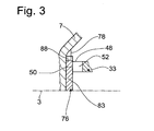
- Fig. 3
- eine Herauszeichnung eines zur Axiallagerung der Nabe dienenden Abschnittes des Kupplungsgehäuses.
- In
Fig. 1 ist eine hydrodynamische Kopplungsvorrichtung 1 dargestellt, ausgebildet als hydrodynamischer Drehmomentwandler. Die hydrodynamische Kopplungsvorrichtung 1 weist ein Kupplungsgehäuse 5 auf, das um eine Drehachse 3 Rotationsbewegungen auszuführen vermag. Das Kupplungsgehäuse 5 verfügt an seiner einem nicht gezeigten Antrieb, wie beispielsweise einer Kurbelwelle einer Brennkraftmaschine, zugewandten Seite über eine antriebsseitige Gehäusewandung 7, die mit einer Pumpenradschale 9 fest verbunden ist. Diese geht im radial inneren Bereich in eine Pumpenradnabe 11 über. - Zurückkommend auf die antriebsseitige Gehäusewandung 7, weist diese an ihrer dem nicht gezeigten Antrieb zugewandten Seite einen Lagerzapfen 13 auf, der in bekannter und daher nicht näher dargestellter Weise an einem Element des Antriebs, wie beispielsweise der Kurbelwelle, zur antriebsseitigen Aufnahme des Kupplungsgehäuses 5 vorgesehen ist. Weiterhin verfügt die antriebsseitige Gehäusewandung 7 über eine Befestigungsaufnahme 15, die üblicherweise zur Befestigung des Kupplungsgehäuses 5 am Antrieb dient, und zwar vorzugsweise über eine nicht gezeigte Flexplatte. Bezüglich einer zeichnerischen Darstellung der Aufnahme des Lagerzapfens eines hydrodynamischen Kopplungselementes in einer Kurbelwelle eines Antriebs sowie einer Anbindung des hydrodynamischen Kopplungselementes über eine Flexplatte an die Kurbelwelle wird beispielhaft auf die
DE 32 22 119 C1 ,Fig. 1 verwiesen. - Die bereits erwähnte Pumpenradschale 9 bildet zusammen mit Pumpenradschaufeln 16 ein Pumpenrad 17, das mit einem eine Turbinenradschale 21 sowie Turbinenradschaufeln 22 aufweisenden Turbinenrad 19 sowie mit einem Leitrad 23 zusammenwirkt. Pumpenrad 17, Turbinenrad 19 und Leitrad 23 bilden in bekannter Weise einen hydrodynamischen Kreis 24, der einen Innentorus 25 umschließt.
- Erwähnt werden sollte weiterhin, dass Leitradschaufeln 28 des Leitrades 23 auf einer Leitradnabe 26 vorgesehen sind, die auf einem Freilauf 27 angeordnet ist. Der Letztgenannte stützt sich über eine Axiallagerung 29 an der Pumpenradnabe 11 axial ab und steht über eine Verzahnung 32 in drehfester, aber axial relativ verschiebbarer Verbindung mit einer Stützwelle 30, die radial innerhalb der Pumpenradnabe 11 angeordnet ist. Die als Hohlwelle ausgebildete Stützwelle 30 ihrerseits umschließt eine als Abtrieb 110 der hydrodynamischen Kopplungsvorrichtung 1 dienende Getriebeeingangswelle 36, die mit einer Mittenbohrung 37 versehen ist. Diese Mittenbohrung 37 nimmt eine Hülse 43 auf, und zwar derart, dass die Hülse 43 mittels Abstützbereichen 45 radial in der Mittenbohrung 37 zentriert ist. Mit Axialversatz zu diesen Abstützbereichen 45 bildet die Hülse 43 radial zwischen sich und der umschließenden Wand der Mittenbohrung 37 einen ersten Versorgungskanal 58 für fluidförmiges Medium aus. Radial innerhalb der Hülse 43 verbleibt ein zentraler Versorgungskanal 47.
- Die Getriebeeingangswelle 36 nimmt über eine Verzahnung 34 eine Nabe 33 drehfest, aber axial verschiebbar auf, wobei diese Nabe 33 in einem radial äußeren Bereich zur Befestigung eines Bauteils 12 eines Torsionsschwingungsdämpfers 90 dient, und dieses Bauteil 12 durch eine abtriebsseitige Nabenscheibe 92 des Torsionsschwingungsdämpfers 90 gebildet wird. Diese Nabenscheibe 92 wirkt über einen Umfangsfedersatz 94 mit zwei Deckblechen 96, 98 als weiteren Bauteilen des Torsionsschwingungsdämpfers 90 zusammen, wobei das Deckbleche 98 zur Aufnahme eines Turbinenradfußes 31 mittels einer Nietverbindung 63 dient, während das andere Deckblech 96 zur Befestigung eines Innenlamellenträgers 64 einer Kupplungsvorrichtung 65, die als Lamellenkupplung ausgebildet ist, vorgesehen ist. Die Kupplungsvorrichtung 65 verfügt sowohl über innere Kupplungselemente 66, die über eine am Innenlamellenträger 64 vorgesehene Verzahnung 70 drehfest mit demselben sind, als auch über äußere Kupplungselemente 68, die mit den inneren Kupplungselementen 68 in Wirkverbindung bringbar sind, wobei die äußeren Kupplungselemente 68 über eine als Außenlamellenträger 69 wirksame Verzahnung 72 mit der antriebsseitigen Wandung 7 und damit mit dem Kupplungsgehäuse 5 in Drehverbindung stehen. Die Kupplungsvorrichtung 65 ist mittels eines axial verlagerbaren Kolbens 54 ein- oder ausrückbar, und bildet gemeinsam mit dem Kolben 54 eine Überbrückungskupplung 56 der hydrodynamischen Kopplungsvorrichtung 1. Wie
Fig. 1 zeigt, kann zwischen dem Kolben 54 und dem Torsionsschwingungsdämpfer 90 eine Trennplatte 40 vorgesehen sein, die den hydrodynamsichen Kreis 24 von einem axial durch den Kolben 54 und die Trennplatte 40 begrenzten Versorgungsraum 44 isoliert. An der von diesem Versorgungsraum 44 abgewandten Seite des Kolbens 54 ist, axial durch denselben sowie durch die antriebsseitige Gehäusewandung 7 begrenzt, ein Druckraum 46 vorgesehen. Der Kolben 54 ist im Kupplungsgehäuse 5 zentriert, und gegenüber demselben mittels einer Abdichtung 86 dichtend aufgenommen. - Die Nabe 33, die wegen der Aufnahme des Torsionsschwingungsdämpfers 90, sowie über denselben, mittelbar auch des Turbinenrades 19, nachfolgend als Trägernabe 33 bezeichnet ist, stützt sich einerseits über das Deckblech 98 und eine Axiallagerung 35 am Freilauf 27 ab, und kann sich andererseits mit seinem der antriebsseitigen Wandung 7 zugewandten, einen Axiallagerungsbereich 48 bildenden Ende an einer Axialanlagefläche 50 der antriebsseitigen Gehäusewandung 7 axial abstützen, wobei sich diese Axialanlagefläche 50, ausgehend von der Drehachse 3 des Kupplungsgehäuses 5, nach radial außen erstreckt. Innerhalb des Erstreckungsbereiches dieser Axialanlagefläche 50 ist, ausgehend von der Gegenseite der antriebsseitigen Gehäusewandung 7 des Kupplungsgehäuses 5, der Lagerzapfen 13 befestigt.
- Nach radial innen hin ist die Trägernabe 33 über eine in einer Dichtungsausnehmung 74 (vgl. auch
Fig. 2 ) aufgenommenen Abdichtung 39 gegenüber der Getriebeeingangswelle 36 abgedichtet, nach radial außen durch eine in einer Dichtungsausnehmung 73 aufgenommenen Abdichtung 38 gegenüber dem Kolben 54 der Überbrückungskupplung 56. Durch diese beiden Abdichtungen 38, 39 werden erste Strömungsdurchlässe 52, welche die Trägernabe 33 an ihrem Axiallagerungsbereich 48 durchdringen und mit Vorzug als Nutungen 85 (vgl.Fig. 2 ) im Axiallagerungsbereich 48 ausgebildet sind, von zweiten Strömungsdurchlässen 55, welche im axialen Erstreckungsbereich der Trägernabe 33 zwischen dem Kolben 54 und dem Torsionsschwingungsdämpfer 90 ausgebildet sind, getrennt. Die ersten Strömungsdurchlässe 52 stehen mit dem zentralen Versorgungskanal 47 der Hülse 47, die als erster abtriebsseitiger Strömungsweg 80 wirksam ist, in Strömungsverbindung, die zweiten Strömungsdurchlässe 55 dagegen mit dem ersten Versorgungskanal 58 radial zwischen der Hülse 43 und der dieselbe umschließenden Wand der Mittenbohrung 37 der Getriebeeingangswelle 36, wobei dieser Versorgungskanal 58 als zweiter abtriebsseitiger Strömungsweg 82 wirksam ist. Darüber hinaus ist ein zweiter Versorgungskanal 60 radial zwischen der Pumpenradnabe 11 und der Stützwelle 30 vorgesehen, der als dritter abtriebsseitiger Strömungsweg 84 dient. - Der erste abtriebsseitige Strömungsweg 80 dient, über die ersten Strömungsdurchlässe 52, zur Herstellung eines Überdruckes im Druckraum 46 gegenüber dem Versorgungsraum 44 und damit zur Druckbeaufschlagung des Kolbens 54 der Überbrückungskupplung 56 zum Einrücken in Richtung zur Kupplungsvorrichtung 65, wodurch eine Reibverbindung zwischen den einzelnen Kupplungselementen 66, 68 hergestellt wird. Zur Erzeugung dieses Überdruckes im Druckraum 46 gegenüber dem Versorgungsraum 44 ist eine Verbindung des ersten abtriebsseitigen Strömungsweges 80 mit einer Steuervorrichtung und einem Hydraulikflüssigkeitsvorrat erforderlich. Weder die Steuervorrichtung noch der Hydraulikflüssigkeitsvorrat sind zeichnerisch dargestellt, können aber der
Fig. 1 derDE 44 23 640 A1 entnommen werden, und sind daher als inhaltlich in die jetzt vorliegende Patentanmeldung aufgenommen zu betrachten. - Der zweite abtriebsseitige Strömungsweg 82 dient, über die Verzahnung 34 und die zweiten Strömungsdurchlässe 55, mit dem Versorgungsraum 44 zur Herstellung eines Überdruckes in demselben gegenüber dem Druckraum 46, und damit zur Druckbeaufschlagung des Kolbens 54 der Überbrückungskupplung 56 zum Ausrücken in von der Kupplungsvorrichtung 65 fortweisender Richtung, wodurch die Reibverbindung zwischen den einzelnen Kupplungselementen 66, 68 der Kupplungsvorrichtung 65 gelöst wird. Zur Herstellung dieses Überdruckes im Versorgungsraum 44 gegenüber dem Druckraum 46 ist eine Verbindung des zweiten abtriebsseitigen Strömungsweges 82 mit der bereits erwähnten Steuervorrichtung und dem ebenfalls genannten Hydraulikflüssigkeitsvorrat erforderlich.
- Fluidförmiges Medium, das über den zweiten abtriebsseitigen Strömungsweg 82 sowie die zweiten Strömungsdurchlässe 55 in den Versorgungsraum 44 gelangt ist, tritt, nach Kühlung der Kupplungselemente 66, 68 der Kupplungsvorrichtung 75, in den hydrodynamischen Kreis 24, um von dort aus über den dritten abtriebsseitiger Strömungsweg 84 wieder auszutreten.
- Zurückkommend auf die antriebsseitige Gehäusewandung 7 des Kupplungsgehäuses 5, ist bei dieser die als Axiallagerung 76 wirksame Axialanlagefläche 50 im radialen Erstreckungsbereich einer Axialausnehmung 78 vorgesehen, die mittels eines Bogenverlaufs 102 in den radial benachbarten Bereich 100 der antriebsseitigen Gehäusewandung 7 übergeht. Die Axialausnehmung 78 ist hierbei radial größer als die Radialerstreckung des Axiallagerungsbereichs 48 der Trägernabe 33, so dass selbst ungünstige Radialtoleranzen bei der Positionierung der Getriebeeingangswelle 36 und/oder der Trägernabe 33 bezüglich der Axiallagerung der Trägernabe 33 problemfrei verkraftet werden können.
- Die Trägernabe 33 ist mit Vorzug mittels eines Sinterverfahrens hergestellt und besteht daher aus einem Sintermetall. Auf diese Weise ist nicht nur eine aufwändigere Geometrie der Trägernabe 33 problemlos herstellbar, sondern darüber hinaus weist die Trägernabe 33 auch eine vergleichsweise hohe Festigkeit auf, die sich insbesondere an dem einer Relativbewegung gegenüber der antriebsseitigen Gehäusewandung 7 unterworfenen Axiallagerungsbereich 48 der Trägernabe 33 durch geringen Verschleiß vorteilhaft bemerkbar macht. Um auch an der antriebsseitigen Gehäusewandung 7 erhöhten Verschleiß zu vermeiden, kann es sinnvoll sein, in die Axialausnehmung 78 ein Axialanlagerelement 83 einzubringen, das bevorzugt aus einem Werkstoff großer Härte, wie beispielsweise einem Federstahl, besteht,um dieses Axialanlagerelement 83 als Axiallagerung 76 für den Axiallagerungsbereich 48 der Trägernabe 33 zu verwenden. Dieses Axialanlagerelement 83 weist hierzu an seiner dem Axiallagerungsbereich 48 der Trägernabe 33 zugewandten Seite die benötigte Axialanlagefläche 50 auf. Das Axialanlagerelement 83 kann drehgesichert an der antriebsseitigen Gehäusewandung 7 aufgenommen sein, beispielsweise mittels einer Verzahnung 88.
- Alternativ kann die antriebsseitige Gehäusewandung 7 im radialen Erstreckungsbereich der Axialausnehmung 78 über eine Anprägung verfügen, um auf diese Weise eine Axialanlagefläche 50 für den Axiallagerungsbereich 48 der Trägernabe 33 mit hoher Oberflächengüte zu schaffen, und damit verschleißfördernde Reibungseffekte zu minimieren.
-
- 1.
- hydrodyn. Kopplungsvorrichtung
- 3.
- Drehachse
- 5.
- Kupplungsgehäuse
- 7.
- antriebsseitige Gehäusewandung
- 9.
- Pumpenradschale
- 11.
- Pumpenradnabe
- 12.
- Bauteil eines TD
- 13.
- Lagerzapfen
- 15.
- Befestigungsaufnahme
- 16
- Pumpenradschaufeln
- 17.
- Pumpenrad
- 19.
- Turbinenrad
- 21.
- Turbinenradschale
- 22
- Turbinenradschaufeln
- 23.
- Leitrad
- 24.
- hydrodynamischer Kreis
- 25.
- Innentorus
- 26.
- Leitradnabe
- 27.
- Freilauf
- 28
- Leitradschaufeln
- 29.
- Axiallagerung
- 30.
- Stützwelle
- 31.
- Turbinenradfuss
- 32
- Verzahnung
- 33.
- Nabe
- 34
- Verzahnung
- 35.
- Axiallagerung
- 36.
- Getriebeeingangswelle
- 37.
- Mittenbohrung
- 38.
- Abdichtung
- 39.
- Abdichtung
- 42.
- Trennplatte
- 43.
- Hülse
- 44.
- Versorgungsraum
- 45.
- Abstützbereiche
- 46.
- Druckraum
- 47.
- Versorgungskanal
- 48.
- Axiallagerungsbereich der Nabe
- 50.
- Axialanlagefläche
- 52.
- erste Strömungsdurchlässe
- 54.
- Kolben
- 55.
- zweite Strömungsdurchlässe
- 56.
- Überbrückungskupplung
- 58.
- erster Versorgungskanal
- 60.
- zweiter Versorgungskanal
- 63
- Nietverbindung
- 64.
- Innenlamellenträger
- 65.
- Kupplungsvorrichtung
- 66.
- innere Kupplungselemente
- 68.
- äußere Kupplungselemente
- 69.
- Außenlamellenträger
- 70.
- Verzahnung
- 72.
- Verzahnung
- 73.
- Dichtungsausnehmung
- 80.
- erster abtriebsseit. Strömungsweg
- 82.
- zweiter abtriebseit. Strömungsweg
- 83.
- Axialanlagerelement
- 84.
- dritter abtriebseit. Strömungsweg
- 85.
- Nutungen
- 86.
- Abdichtung
- 88.
- Verzahnung
- 90.
- Torsionsschwingungsdämpfer
- 92.
- abtriebsseitige Nabenscheibe
- 94.
- Umfangsfedersatz
- 96.
- Deckblech
- 98.
- Deckblech
- 100.
- radial benachbarter Bereich
- 102.
- Bogenverlauf
- 110.
- Abtrieb
- 74.
- Dichtungsausnehmung
- 76
- Axiallagerung
- 78.
- Axialausnehmung
Claims (9)
- Hydrodynamische Kopplungsvorrichtung mit einem zumindest durch ein Pumpenrad und ein Turbinenrad gebildeten hydrodynamischen Kreis in einem Kupplungsgehäuse und mit einer Überbrückungskupplung, die einen mit einer antriebsseitigen Gehäusewandung des Kupplungsgehäuses verbindbaren, in Achsrichtung zu einer Auslenkbewegung befähigten Kolben aufweist, wobei das Turbinenrad zumindest in Achsrichtung mit einer Nabe in Wirkverbindung steht, die mit einem Abtrieb in Drehverbindung steht, sich einerseits an einem Bauteil des hydrodynamischen Kreises und andererseits an einem Bauteil des Kupplungsgehäuses axial abstützt und über erste Strömungsdurchlässe sowie, mit Axialversatz gegenüber denselben, über zweite Strömungsdurchlässe jeweils zur Passage von Strömungsfluid verfügt, von denen die ersten Strömungsdurchlässe wenigstens einen ersten abtriebsseitigen Strömungsweg mit einem Druckraum, der zumindest im wesentlichen durch die antriebsseitige Gehäusewandung des Kupplungsgehäuses sowie den Kolben begrenzt ist, verbinden, während die zweiten Strömungsdurchlässe zumindest einen zweiten abtriebsseitigen Strömungsweg mit einem Versorgungsraum verbinden, der an die vom Druckraum abgewandte Seite des Kolbens angrenzt,
dadurch gekennzeichnet,
dass die antriebsseitige Gehäusewandung (7) zur Bildung einer Axialabstützung für die Nabe (33) zumindest im wesentlichen bis an eine Drehachse (3) des Kupplungsgehäuses (5) nach radial innen gezogen ist, und die Nabe (33) mit ihrem der antriebsseitigen Gehäusewandung (7) zugewandten, als Axiallagerungsbereich (48) ausgebildeten antriebsseitigen Ende in Axialanlage mit einer Axiallagerung (76) versetzbar ist, die entweder als Axialanlagefläche (50) an der antriebsseitigen Gehäusewandung (7) vorgesehen ist, oder aber der antriebsseitigen Gehäusewandung (7) zugeordnet ist. - Hydrodynamische Kopplungsvorrichtung nach Anspruch 1
dadurch gekennzeichnet,
dass die Axialanlagefläche (50) in einer Axialausnehmung (78) der antriebsseitigen Gehäusewandung (7) vorgesehen ist. - Hydrodynamische Kopplungsvorrichtung nach Anspruch 2,
dadurch gekennzeichnet,
dass die Axialausnehmung (78) der antriebsseitigen Gehäusewandung (7) in Radialrichtung über die Erstreckungsweite des benachbarten Axiallagerungsbereichs (48) der Nabe (33) hinaus reicht, und zumindest im wesentlichen mittels eines Bogenverlaus (102) von der Axialanlagefläche (50) in den radial benachbarten Bereich (100) der antriebsseitigen Gehäusewandung (7) überführt. - Hydrodynamische Kopplungsvorrichtung nach Anspruch 3,
dadurch gekennzeichnet,
dass die Axialausnehmung (78) zur Aufnahme eines Axialanlagerelementes (83) großer Härte dient. - Hydrodynamische Kopplungsvorrichtung nach Anspruch 2,
dadurch gekennzeichnet,
dass die Axialanlagefläche (50) in ihrem Übergangsbereich zur radial benachbarten antriebsseitigen Gehäusewandung (7) über eine Anprägung verfügt, an welcher die Nabe (33) mit ihrem Axiallagerungsbereich (48) in Axialanlage gelangt. - Hydrodynamische Kopplungsvorrichtung nach einem der Ansprüche 1 bis 5,
dadurch gekennzeichnet,
dass die Nabe (33) mittels eines Sinterverfahrens hergestellt ist, und somit aus einem Sinterwerkstoff besteht. - Hydrodynamische Kopplungsvorrichtung nach einem der Ansprüche 1 bis 6,
dadurch gekennzeichnet,
dass die Nabe (33) zur unmittelbaren Aufnahme des Kolbens (54) der Überbrückungskupplung dient und eine gegenüber dem Kolben (54) wirksame Abdichtung (38) aufweist. - Hydrodynamische Kopplungsvorrichtung nach einem der Ansprüche 1 bis 7,
dadurch gekennzeichnet,
dass die Nabe (33) mit einer gegenüber dem Abtrieb (110) wirksamen Abdichtung (39) ausgebildet ist. - Hydrodynamische Kopplungsvorrichtung nach einem der Ansprüche 1 bis 8,
dadurch gekennzeichnet,
dass die Nabe (33) zur Bildung der ersten Strömungsdurchlässe (52) an ihrem der antriebsseitigen Gehäusewandung (7) zugewandten Axiallagerungsbereich (48) mit Nutungen (85) ausgebildet ist.
Applications Claiming Priority (1)
| Application Number | Priority Date | Filing Date | Title |
|---|---|---|---|
| DE102007014312A DE102007014312A1 (de) | 2007-03-26 | 2007-03-26 | Hydrodynamische Kopplungsvorrichtung |
Publications (3)
| Publication Number | Publication Date |
|---|---|
| EP1975467A2 true EP1975467A2 (de) | 2008-10-01 |
| EP1975467A3 EP1975467A3 (de) | 2011-08-10 |
| EP1975467B1 EP1975467B1 (de) | 2012-09-19 |
Family
ID=39577300
Family Applications (1)
| Application Number | Title | Priority Date | Filing Date |
|---|---|---|---|
| EP08004831A Not-in-force EP1975467B1 (de) | 2007-03-26 | 2008-03-14 | Hydrodynamische Kopplungsvorrichtung |
Country Status (3)
| Country | Link |
|---|---|
| US (1) | US8042666B2 (de) |
| EP (1) | EP1975467B1 (de) |
| DE (1) | DE102007014312A1 (de) |
Families Citing this family (4)
| Publication number | Priority date | Publication date | Assignee | Title |
|---|---|---|---|---|
| DE102010002846B4 (de) * | 2010-03-15 | 2022-03-24 | Zf Friedrichshafen Ag | Drehmomentübertragungsbaugruppe, insbesondere für den Antriebsstrang eines Fahrzeugs |
| JP5202719B1 (ja) * | 2011-12-05 | 2013-06-05 | 株式会社エクセディ | トルクコンバータのロックアップ装置 |
| JP6695624B2 (ja) * | 2016-02-16 | 2020-05-20 | ジヤトコ株式会社 | 油路構造 |
| KR101836728B1 (ko) * | 2016-10-24 | 2018-03-08 | 현대자동차주식회사 | 차량용 토크컨버터 |
Citations (6)
| Publication number | Priority date | Publication date | Assignee | Title |
|---|---|---|---|---|
| JPH03260463A (ja) | 1990-03-07 | 1991-11-20 | Mazda Motor Corp | 自動変速機の制御装置 |
| DE19754652A1 (de) | 1997-12-09 | 1999-06-17 | Mannesmann Sachs Ag | Drehmomentwandler |
| JP2001116110A (ja) | 1999-10-19 | 2001-04-27 | Jatco Transtechnology Ltd | 多板式ロックアップクラッチ付きトルクコンバータ |
| DE19758677C2 (de) | 1996-05-29 | 2003-02-13 | Exedy Corp | Drehmomentwandler mit Überbrückungskupplung |
| DE102007058014A1 (de) | 2006-12-27 | 2008-07-03 | Luk Lamellen Und Kupplungsbau Beteiligungs Kg | Dichtungshaltereinrichtung und Kraftübertragungsvorrichtung mit Dichtungshaltereinrichtung |
| EP1977141B1 (de) | 2006-01-12 | 2009-11-18 | LuK Lamellen und Kupplungsbau Beteiligungs KG | Wandler mit zwangs-ölführung |
Family Cites Families (13)
| Publication number | Priority date | Publication date | Assignee | Title |
|---|---|---|---|---|
| DE3222119C1 (de) * | 1982-06-11 | 1983-10-27 | Daimler-Benz Ag, 7000 Stuttgart | Axial nachgiebige Mitnehmerscheibe |
| ES2122821B1 (es) * | 1993-12-22 | 1999-07-01 | Fichtel & Sachs Ag | Convertidor de par de giro hidrodinamico con embrague de puente. |
| DE4423640C2 (de) | 1993-12-22 | 1997-08-21 | Fichtel & Sachs Ag | Hydrodynamischer Drehmomentwandler mit Überbrückungskupplung |
| US5682969A (en) * | 1995-10-04 | 1997-11-04 | Ford Global Technologies, Inc. | Resilient input to a lockup clutch |
| JP3854661B2 (ja) * | 1996-05-29 | 2006-12-06 | 株式会社エクセディ | ロックアップ装置付きトルクコンバータ |
| US5819896A (en) * | 1996-10-28 | 1998-10-13 | Ford Motor Company | Variable flow rate torque converter lockup clutch |
| US6053292A (en) * | 1999-01-25 | 2000-04-25 | Ford Global Technologies, Inc. | Torque converter having resiliently loaded bypass clutch piston |
| DE19932576B4 (de) * | 1999-07-13 | 2011-03-03 | Zf Sachs Ag | Hydrodynamischer Drehmomentwandler |
| US6508346B1 (en) * | 2000-10-16 | 2003-01-21 | Ford Global Technologies, Inc. | Torque converter assembly |
| DE10125438A1 (de) * | 2001-05-25 | 2002-11-28 | Zf Sachs Ag | Torsionsschwingungsdämpfer für einen hydrodynamischen Drehmomentwandler |
| DE502006005429D1 (de) * | 2006-01-12 | 2009-12-31 | Luk Lamellen & Kupplungsbau | Wandler mit zwangs-ölführung |
| DE102006009987A1 (de) * | 2006-03-03 | 2007-09-06 | Zf Friedrichshafen Ag | Hydrodynamische Kopplungsvorrichtung |
| DE102007014311A1 (de) * | 2007-03-26 | 2008-10-02 | Zf Friedrichshafen Ag | Hydrodynamische Kopplungsvorrichtung |
-
2007
- 2007-03-26 DE DE102007014312A patent/DE102007014312A1/de not_active Withdrawn
-
2008
- 2008-03-14 EP EP08004831A patent/EP1975467B1/de not_active Not-in-force
- 2008-03-26 US US12/079,391 patent/US8042666B2/en not_active Expired - Fee Related
Patent Citations (6)
| Publication number | Priority date | Publication date | Assignee | Title |
|---|---|---|---|---|
| JPH03260463A (ja) | 1990-03-07 | 1991-11-20 | Mazda Motor Corp | 自動変速機の制御装置 |
| DE19758677C2 (de) | 1996-05-29 | 2003-02-13 | Exedy Corp | Drehmomentwandler mit Überbrückungskupplung |
| DE19754652A1 (de) | 1997-12-09 | 1999-06-17 | Mannesmann Sachs Ag | Drehmomentwandler |
| JP2001116110A (ja) | 1999-10-19 | 2001-04-27 | Jatco Transtechnology Ltd | 多板式ロックアップクラッチ付きトルクコンバータ |
| EP1977141B1 (de) | 2006-01-12 | 2009-11-18 | LuK Lamellen und Kupplungsbau Beteiligungs KG | Wandler mit zwangs-ölführung |
| DE102007058014A1 (de) | 2006-12-27 | 2008-07-03 | Luk Lamellen Und Kupplungsbau Beteiligungs Kg | Dichtungshaltereinrichtung und Kraftübertragungsvorrichtung mit Dichtungshaltereinrichtung |
Also Published As
| Publication number | Publication date |
|---|---|
| US20080236974A1 (en) | 2008-10-02 |
| EP1975467B1 (de) | 2012-09-19 |
| US8042666B2 (en) | 2011-10-25 |
| DE102007014312A1 (de) | 2008-10-02 |
| EP1975467A3 (de) | 2011-08-10 |
Similar Documents
| Publication | Publication Date | Title |
|---|---|---|
| EP2481952B1 (de) | Hydrodynamische Kopplungsvorrichtung | |
| DE10362274C5 (de) | Torsionsschwingungsdämpfer | |
| DE19861492B4 (de) | Hydrodynamischer Drehmomentwandler | |
| EP1464873B1 (de) | Torsionsschwingungsdämpfer für Drehmomentwandler | |
| EP1462678B1 (de) | Hydrodynamische Kupplungsanordnung mit einer Kupplungsvorrichtung innerhalb des Kupplungsgehäuses | |
| EP1983221A2 (de) | Hydrodynamische Kopplungsanordnung | |
| EP1511947A1 (de) | Gangschaltgetriebe für ein kraftfahrzeug mit hydraulisch betätigbarer mehrfachkupplung | |
| EP1698799B1 (de) | Torsionsschwingungsdämpfer | |
| EP1528289A2 (de) | Torsionsschwingungsdämpfer | |
| WO1999008022A1 (de) | Hydrodynamischer drehmomentwandler | |
| EP1983220A2 (de) | Hydrodynamische Kopplungsanordnung | |
| EP1975467B1 (de) | Hydrodynamische Kopplungsvorrichtung | |
| EP1826459A1 (de) | Drehmomentwandler mit Überbrückungskupplung | |
| DE10358902A1 (de) | Torsionsschwingungsdämpfer | |
| DE2544173A1 (de) | Automatisches getriebe fuer kraftfahrzeuge | |
| DE10347782B4 (de) | Hydrodynamischer Drehmomentwandler | |
| DE4414519C2 (de) | Hydrokinetischer Drehmomentwandler mit Überbrückungskupplung | |
| WO2017182196A1 (de) | Torsionsschwingungsdämpfer | |
| WO2017137179A1 (de) | Kopplungsanordnung | |
| EP2014953A2 (de) | Hydrodynamische Kopplungsanordnung | |
| EP2014952A1 (de) | Hydrodynamische Kopplungsanordnung | |
| DE19846444B4 (de) | Hydrodynamischer Drehmomentwandler | |
| DE69611342T2 (de) | Schaltvorrichtung eines automatischen Stufengetriebes | |
| EP3348866B1 (de) | Hydrodynamische kopplungsanordnung | |
| DE102006009967A1 (de) | Hydrodynamische Kopplungsvorrichtung |
Legal Events
| Date | Code | Title | Description |
|---|---|---|---|
| PUAI | Public reference made under article 153(3) epc to a published international application that has entered the european phase |
Free format text: ORIGINAL CODE: 0009012 |
|
| AK | Designated contracting states |
Kind code of ref document: A2 Designated state(s): AT BE BG CH CY CZ DE DK EE ES FI FR GB GR HR HU IE IS IT LI LT LU LV MC MT NL NO PL PT RO SE SI SK TR |
|
| AX | Request for extension of the european patent |
Extension state: AL BA MK RS |
|
| PUAL | Search report despatched |
Free format text: ORIGINAL CODE: 0009013 |
|
| AK | Designated contracting states |
Kind code of ref document: A3 Designated state(s): AT BE BG CH CY CZ DE DK EE ES FI FR GB GR HR HU IE IS IT LI LT LU LV MC MT NL NO PL PT RO SE SI SK TR |
|
| AX | Request for extension of the european patent |
Extension state: AL BA MK RS |
|
| RIC1 | Information provided on ipc code assigned before grant |
Ipc: F16H 45/02 20060101AFI20110701BHEP |
|
| 17P | Request for examination filed |
Effective date: 20120113 |
|
| AKX | Designation fees paid |
Designated state(s): AT BE BG CH CY CZ DE DK EE ES FI FR GB GR HR HU IE IS IT LI LT LU LV MC MT NL NO PL PT RO SE SI SK TR |
|
| GRAP | Despatch of communication of intention to grant a patent |
Free format text: ORIGINAL CODE: EPIDOSNIGR1 |
|
| GRAS | Grant fee paid |
Free format text: ORIGINAL CODE: EPIDOSNIGR3 |
|
| GRAA | (expected) grant |
Free format text: ORIGINAL CODE: 0009210 |
|
| AK | Designated contracting states |
Kind code of ref document: B1 Designated state(s): AT BE BG CH CY CZ DE DK EE ES FI FR GB GR HR HU IE IS IT LI LT LU LV MC MT NL NO PL PT RO SE SI SK TR |
|
| REG | Reference to a national code |
Ref country code: GB Ref legal event code: FG4D Free format text: NOT ENGLISH |
|
| REG | Reference to a national code |
Ref country code: CH Ref legal event code: EP |
|
| REG | Reference to a national code |
Ref country code: IE Ref legal event code: FG4D Free format text: LANGUAGE OF EP DOCUMENT: GERMAN |
|
| REG | Reference to a national code |
Ref country code: AT Ref legal event code: REF Ref document number: 576206 Country of ref document: AT Kind code of ref document: T Effective date: 20121015 |
|
| REG | Reference to a national code |
Ref country code: DE Ref legal event code: R096 Ref document number: 502008008208 Country of ref document: DE Effective date: 20121115 |
|
| PG25 | Lapsed in a contracting state [announced via postgrant information from national office to epo] |
Ref country code: HR Free format text: LAPSE BECAUSE OF FAILURE TO SUBMIT A TRANSLATION OF THE DESCRIPTION OR TO PAY THE FEE WITHIN THE PRESCRIBED TIME-LIMIT Effective date: 20120919 Ref country code: CY Free format text: LAPSE BECAUSE OF FAILURE TO SUBMIT A TRANSLATION OF THE DESCRIPTION OR TO PAY THE FEE WITHIN THE PRESCRIBED TIME-LIMIT Effective date: 20120919 Ref country code: LT Free format text: LAPSE BECAUSE OF FAILURE TO SUBMIT A TRANSLATION OF THE DESCRIPTION OR TO PAY THE FEE WITHIN THE PRESCRIBED TIME-LIMIT Effective date: 20120919 Ref country code: FI Free format text: LAPSE BECAUSE OF FAILURE TO SUBMIT A TRANSLATION OF THE DESCRIPTION OR TO PAY THE FEE WITHIN THE PRESCRIBED TIME-LIMIT Effective date: 20120919 Ref country code: NO Free format text: LAPSE BECAUSE OF FAILURE TO SUBMIT A TRANSLATION OF THE DESCRIPTION OR TO PAY THE FEE WITHIN THE PRESCRIBED TIME-LIMIT Effective date: 20121219 |
|
| REG | Reference to a national code |
Ref country code: NL Ref legal event code: VDEP Effective date: 20120919 |
|
| REG | Reference to a national code |
Ref country code: LT Ref legal event code: MG4D Effective date: 20120912 |
|
| PG25 | Lapsed in a contracting state [announced via postgrant information from national office to epo] |
Ref country code: SE Free format text: LAPSE BECAUSE OF FAILURE TO SUBMIT A TRANSLATION OF THE DESCRIPTION OR TO PAY THE FEE WITHIN THE PRESCRIBED TIME-LIMIT Effective date: 20120919 Ref country code: LV Free format text: LAPSE BECAUSE OF FAILURE TO SUBMIT A TRANSLATION OF THE DESCRIPTION OR TO PAY THE FEE WITHIN THE PRESCRIBED TIME-LIMIT Effective date: 20120919 Ref country code: GR Free format text: LAPSE BECAUSE OF FAILURE TO SUBMIT A TRANSLATION OF THE DESCRIPTION OR TO PAY THE FEE WITHIN THE PRESCRIBED TIME-LIMIT Effective date: 20121220 Ref country code: SI Free format text: LAPSE BECAUSE OF FAILURE TO SUBMIT A TRANSLATION OF THE DESCRIPTION OR TO PAY THE FEE WITHIN THE PRESCRIBED TIME-LIMIT Effective date: 20120919 |
|
| PG25 | Lapsed in a contracting state [announced via postgrant information from national office to epo] |
Ref country code: NL Free format text: LAPSE BECAUSE OF FAILURE TO SUBMIT A TRANSLATION OF THE DESCRIPTION OR TO PAY THE FEE WITHIN THE PRESCRIBED TIME-LIMIT Effective date: 20120919 Ref country code: EE Free format text: LAPSE BECAUSE OF FAILURE TO SUBMIT A TRANSLATION OF THE DESCRIPTION OR TO PAY THE FEE WITHIN THE PRESCRIBED TIME-LIMIT Effective date: 20120919 Ref country code: RO Free format text: LAPSE BECAUSE OF FAILURE TO SUBMIT A TRANSLATION OF THE DESCRIPTION OR TO PAY THE FEE WITHIN THE PRESCRIBED TIME-LIMIT Effective date: 20120919 Ref country code: IS Free format text: LAPSE BECAUSE OF FAILURE TO SUBMIT A TRANSLATION OF THE DESCRIPTION OR TO PAY THE FEE WITHIN THE PRESCRIBED TIME-LIMIT Effective date: 20130119 Ref country code: CZ Free format text: LAPSE BECAUSE OF FAILURE TO SUBMIT A TRANSLATION OF THE DESCRIPTION OR TO PAY THE FEE WITHIN THE PRESCRIBED TIME-LIMIT Effective date: 20120919 Ref country code: ES Free format text: LAPSE BECAUSE OF FAILURE TO SUBMIT A TRANSLATION OF THE DESCRIPTION OR TO PAY THE FEE WITHIN THE PRESCRIBED TIME-LIMIT Effective date: 20121230 |
|
| PG25 | Lapsed in a contracting state [announced via postgrant information from national office to epo] |
Ref country code: SK Free format text: LAPSE BECAUSE OF FAILURE TO SUBMIT A TRANSLATION OF THE DESCRIPTION OR TO PAY THE FEE WITHIN THE PRESCRIBED TIME-LIMIT Effective date: 20120919 Ref country code: PT Free format text: LAPSE BECAUSE OF FAILURE TO SUBMIT A TRANSLATION OF THE DESCRIPTION OR TO PAY THE FEE WITHIN THE PRESCRIBED TIME-LIMIT Effective date: 20130121 Ref country code: PL Free format text: LAPSE BECAUSE OF FAILURE TO SUBMIT A TRANSLATION OF THE DESCRIPTION OR TO PAY THE FEE WITHIN THE PRESCRIBED TIME-LIMIT Effective date: 20120919 |
|
| PLBE | No opposition filed within time limit |
Free format text: ORIGINAL CODE: 0009261 |
|
| STAA | Information on the status of an ep patent application or granted ep patent |
Free format text: STATUS: NO OPPOSITION FILED WITHIN TIME LIMIT |
|
| PG25 | Lapsed in a contracting state [announced via postgrant information from national office to epo] |
Ref country code: DK Free format text: LAPSE BECAUSE OF FAILURE TO SUBMIT A TRANSLATION OF THE DESCRIPTION OR TO PAY THE FEE WITHIN THE PRESCRIBED TIME-LIMIT Effective date: 20120919 Ref country code: BG Free format text: LAPSE BECAUSE OF FAILURE TO SUBMIT A TRANSLATION OF THE DESCRIPTION OR TO PAY THE FEE WITHIN THE PRESCRIBED TIME-LIMIT Effective date: 20121219 |
|
| 26N | No opposition filed |
Effective date: 20130620 |
|
| PG25 | Lapsed in a contracting state [announced via postgrant information from national office to epo] |
Ref country code: IT Free format text: LAPSE BECAUSE OF FAILURE TO SUBMIT A TRANSLATION OF THE DESCRIPTION OR TO PAY THE FEE WITHIN THE PRESCRIBED TIME-LIMIT Effective date: 20120919 |
|
| BERE | Be: lapsed |
Owner name: ZF FRIEDRICHSHAFEN A.G. Effective date: 20130331 |
|
| REG | Reference to a national code |
Ref country code: DE Ref legal event code: R097 Ref document number: 502008008208 Country of ref document: DE Effective date: 20130620 |
|
| PG25 | Lapsed in a contracting state [announced via postgrant information from national office to epo] |
Ref country code: MC Free format text: LAPSE BECAUSE OF NON-PAYMENT OF DUE FEES Effective date: 20130331 |
|
| REG | Reference to a national code |
Ref country code: CH Ref legal event code: PL |
|
| GBPC | Gb: european patent ceased through non-payment of renewal fee |
Effective date: 20130314 |
|
| REG | Reference to a national code |
Ref country code: IE Ref legal event code: MM4A |
|
| PG25 | Lapsed in a contracting state [announced via postgrant information from national office to epo] |
Ref country code: CH Free format text: LAPSE BECAUSE OF NON-PAYMENT OF DUE FEES Effective date: 20130331 Ref country code: LI Free format text: LAPSE BECAUSE OF NON-PAYMENT OF DUE FEES Effective date: 20130331 Ref country code: GB Free format text: LAPSE BECAUSE OF NON-PAYMENT OF DUE FEES Effective date: 20130314 Ref country code: IE Free format text: LAPSE BECAUSE OF NON-PAYMENT OF DUE FEES Effective date: 20130314 Ref country code: BE Free format text: LAPSE BECAUSE OF NON-PAYMENT OF DUE FEES Effective date: 20130331 |
|
| REG | Reference to a national code |
Ref country code: AT Ref legal event code: MM01 Ref document number: 576206 Country of ref document: AT Kind code of ref document: T Effective date: 20130314 |
|
| PG25 | Lapsed in a contracting state [announced via postgrant information from national office to epo] |
Ref country code: MT Free format text: LAPSE BECAUSE OF FAILURE TO SUBMIT A TRANSLATION OF THE DESCRIPTION OR TO PAY THE FEE WITHIN THE PRESCRIBED TIME-LIMIT Effective date: 20120919 |
|
| PG25 | Lapsed in a contracting state [announced via postgrant information from national office to epo] |
Ref country code: AT Free format text: LAPSE BECAUSE OF NON-PAYMENT OF DUE FEES Effective date: 20130314 |
|
| REG | Reference to a national code |
Ref country code: FR Ref legal event code: PLFP Year of fee payment: 8 |
|
| PGFP | Annual fee paid to national office [announced via postgrant information from national office to epo] |
Ref country code: DE Payment date: 20150310 Year of fee payment: 8 |
|
| PGFP | Annual fee paid to national office [announced via postgrant information from national office to epo] |
Ref country code: FR Payment date: 20150309 Year of fee payment: 8 |
|
| PG25 | Lapsed in a contracting state [announced via postgrant information from national office to epo] |
Ref country code: TR Free format text: LAPSE BECAUSE OF FAILURE TO SUBMIT A TRANSLATION OF THE DESCRIPTION OR TO PAY THE FEE WITHIN THE PRESCRIBED TIME-LIMIT Effective date: 20120919 |
|
| PG25 | Lapsed in a contracting state [announced via postgrant information from national office to epo] |
Ref country code: HU Free format text: LAPSE BECAUSE OF FAILURE TO SUBMIT A TRANSLATION OF THE DESCRIPTION OR TO PAY THE FEE WITHIN THE PRESCRIBED TIME-LIMIT; INVALID AB INITIO Effective date: 20080314 Ref country code: LU Free format text: LAPSE BECAUSE OF NON-PAYMENT OF DUE FEES Effective date: 20130314 |
|
| REG | Reference to a national code |
Ref country code: DE Ref legal event code: R119 Ref document number: 502008008208 Country of ref document: DE |
|
| REG | Reference to a national code |
Ref country code: FR Ref legal event code: ST Effective date: 20161130 |
|
| PG25 | Lapsed in a contracting state [announced via postgrant information from national office to epo] |
Ref country code: FR Free format text: LAPSE BECAUSE OF NON-PAYMENT OF DUE FEES Effective date: 20160331 Ref country code: DE Free format text: LAPSE BECAUSE OF NON-PAYMENT OF DUE FEES Effective date: 20161001 |