EP1968757B1 - Verfahren und vorrichtung zum herstellen gebogener federelemente - Google Patents
Verfahren und vorrichtung zum herstellen gebogener federelemente Download PDFInfo
- Publication number
- EP1968757B1 EP1968757B1 EP06819577A EP06819577A EP1968757B1 EP 1968757 B1 EP1968757 B1 EP 1968757B1 EP 06819577 A EP06819577 A EP 06819577A EP 06819577 A EP06819577 A EP 06819577A EP 1968757 B1 EP1968757 B1 EP 1968757B1
- Authority
- EP
- European Patent Office
- Prior art keywords
- bending
- unit
- steel strip
- spring steel
- separating
- Prior art date
- Legal status (The legal status is an assumption and is not a legal conclusion. Google has not performed a legal analysis and makes no representation as to the accuracy of the status listed.)
- Active
Links
Images

Classifications
-
- B—PERFORMING OPERATIONS; TRANSPORTING
- B21—MECHANICAL METAL-WORKING WITHOUT ESSENTIALLY REMOVING MATERIAL; PUNCHING METAL
- B21D—WORKING OR PROCESSING OF SHEET METAL OR METAL TUBES, RODS OR PROFILES WITHOUT ESSENTIALLY REMOVING MATERIAL; PUNCHING METAL
- B21D53/00—Making other particular articles
- B21D53/88—Making other particular articles other parts for vehicles, e.g. cowlings, mudguards
- B21D53/886—Making other particular articles other parts for vehicles, e.g. cowlings, mudguards leaf springs
-
- B—PERFORMING OPERATIONS; TRANSPORTING
- B21—MECHANICAL METAL-WORKING WITHOUT ESSENTIALLY REMOVING MATERIAL; PUNCHING METAL
- B21D—WORKING OR PROCESSING OF SHEET METAL OR METAL TUBES, RODS OR PROFILES WITHOUT ESSENTIALLY REMOVING MATERIAL; PUNCHING METAL
- B21D11/00—Bending not restricted to forms of material mentioned in only one of groups B21D5/00, B21D7/00, B21D9/00; Bending not provided for in groups B21D5/00 - B21D9/00; Twisting
- B21D11/10—Bending specially adapted to produce specific articles, e.g. leaf springs
-
- B—PERFORMING OPERATIONS; TRANSPORTING
- B21—MECHANICAL METAL-WORKING WITHOUT ESSENTIALLY REMOVING MATERIAL; PUNCHING METAL
- B21D—WORKING OR PROCESSING OF SHEET METAL OR METAL TUBES, RODS OR PROFILES WITHOUT ESSENTIALLY REMOVING MATERIAL; PUNCHING METAL
- B21D53/00—Making other particular articles
- B21D53/88—Making other particular articles other parts for vehicles, e.g. cowlings, mudguards
-
- B—PERFORMING OPERATIONS; TRANSPORTING
- B21—MECHANICAL METAL-WORKING WITHOUT ESSENTIALLY REMOVING MATERIAL; PUNCHING METAL
- B21D—WORKING OR PROCESSING OF SHEET METAL OR METAL TUBES, RODS OR PROFILES WITHOUT ESSENTIALLY REMOVING MATERIAL; PUNCHING METAL
- B21D7/00—Bending rods, profiles, or tubes
- B21D7/08—Bending rods, profiles, or tubes by passing between rollers or through a curved die
-
- B—PERFORMING OPERATIONS; TRANSPORTING
- B23—MACHINE TOOLS; METAL-WORKING NOT OTHERWISE PROVIDED FOR
- B23D—PLANING; SLOTTING; SHEARING; BROACHING; SAWING; FILING; SCRAPING; LIKE OPERATIONS FOR WORKING METAL BY REMOVING MATERIAL, NOT OTHERWISE PROVIDED FOR
- B23D25/00—Machines or arrangements for shearing stock while the latter is travelling otherwise than in the direction of the cut
- B23D25/02—Flying shearing machines
- B23D25/04—Flying shearing machines in which a cutting unit moves bodily with the work while cutting
-
- B—PERFORMING OPERATIONS; TRANSPORTING
- B23—MACHINE TOOLS; METAL-WORKING NOT OTHERWISE PROVIDED FOR
- B23D—PLANING; SLOTTING; SHEARING; BROACHING; SAWING; FILING; SCRAPING; LIKE OPERATIONS FOR WORKING METAL BY REMOVING MATERIAL, NOT OTHERWISE PROVIDED FOR
- B23D25/00—Machines or arrangements for shearing stock while the latter is travelling otherwise than in the direction of the cut
- B23D25/02—Flying shearing machines
- B23D25/08—Flying shearing machines having two coacting shearing blades mounted independently
-
- B—PERFORMING OPERATIONS; TRANSPORTING
- B60—VEHICLES IN GENERAL
- B60S—SERVICING, CLEANING, REPAIRING, SUPPORTING, LIFTING, OR MANOEUVRING OF VEHICLES, NOT OTHERWISE PROVIDED FOR
- B60S1/00—Cleaning of vehicles
- B60S1/02—Cleaning windscreens, windows or optical devices
- B60S1/04—Wipers or the like, e.g. scrapers
- B60S1/32—Wipers or the like, e.g. scrapers characterised by constructional features of wiper blade arms or blades
- B60S1/38—Wiper blades
- B60S2001/3898—Wiper blades method for manufacturing wiper blades
-
- Y—GENERAL TAGGING OF NEW TECHNOLOGICAL DEVELOPMENTS; GENERAL TAGGING OF CROSS-SECTIONAL TECHNOLOGIES SPANNING OVER SEVERAL SECTIONS OF THE IPC; TECHNICAL SUBJECTS COVERED BY FORMER USPC CROSS-REFERENCE ART COLLECTIONS [XRACs] AND DIGESTS
- Y10—TECHNICAL SUBJECTS COVERED BY FORMER USPC
- Y10T—TECHNICAL SUBJECTS COVERED BY FORMER US CLASSIFICATION
- Y10T29/00—Metal working
- Y10T29/49—Method of mechanical manufacture
- Y10T29/49609—Spring making
Definitions
- the invention is based on a method and a device for producing curved spring elements according to the preambles of claim 1 and 2. Such a method or device is in the DE 101 15 047 A1 disclosed.
- a method and an apparatus for producing flat-plate wipers for vehicles with bent spring elements are known.
- These form the support element of the wiper blade and preferably have a varying material thickness over the length.
- They are made of a tempered spring steel strip, which is fed by two pairs of feed rollers under a continuous feed on guide rollers of a bending unit.
- the bending unit includes a separation unit, by which the individual support elements are separated from each other after bending. During the separation process, the continuous feed is briefly interrupted.
- the spring steel strip is first bent in one direction by three systems and bent back by a small percentage by a subsequent contact point.
- the degree of backbone required to ensure the dimensional stability of the curved support member is determined empirically. As a mean value, depending on the quality of the spring steel strip, a degree of re-bending of about 10% to 40% of the previous bending has proven favorable.
- the first two support points of the bending device in the conveying direction are formed by bending rollers, while the third support point is a cutting edge, which cooperates with a cutting blade, and separates the finished bent support member from the spring steel strip.
- the bending rollers can be adjusted by adjusting motors on the spring steel strip to and from the spring steel strip away. According to the position of the bending rollers results in a predetermined bending of the spring steel strip. Actuators are activated programmatically by an electronic control unit as a function of various parameters.
- the apparatus comprises a feed unit which feeds a spring steel strip from a supply roll of a bending unit. Between the feed unit and the bending unit a straightening apparatus is provided.
- the bending unit comprises three bending rollers and a return bending roller, of which a bending roller and the return bending roller can be delivered via an adjusting device transversely to the spring steel strip.
- the bending unit is followed by a separation unit, which is connected to an NC control unit and the individual spring band sections separated from the spring steel strip. During the separation process, the spring-belt feed is briefly stopped.
- the feed of the spring steel strip is not interrupted.
- the separating tools are moved numerically controlled in the longitudinal direction of the spring steel strip and are synchronized during the separation process with the feed movement of the spring steel strip.
- the uniform feed rate results in an equally uniform bending curve in the bending unit, which has a positive effect on the properties of the bent spring elements.
- the known devices operate with a start-stop system with very different speeds and large accelerations during a feed and bending operation, especially when large quantities per unit time to be produced.
- the intermittent feed takes up the components and leads to greater wear. Due to the continuous feed a better interaction of the drive motors takes place to each other, so that less wear occurs and a higher output is possible.
- to control the process can be dispensed with so-called trigger holes in the spring steel strip. These can lead to large differences in length and bending inaccuracies.
- the separating tools are arranged in the longitudinal direction of the advancing movement of the spring steel strip relative to this adjustable, wherein their adjustment by an electronic control unit during the separation process with the pushing movement of the spring steel bands is synchronized. It is possible that the separating tools are adjustable together with the separation unit in the longitudinal direction of the advancing movement of the spring steel strip relative to this, or that the separating tools are arranged in a fixed housing of the separation unit, in which they relative to the housing and in the longitudinal direction of the advancing movement of the spring steel strip are adjustable relative to this.
- the second alternative is easier to implement, and the cutting tools are more precise to control.
- roller guide To guide the spring steel strip between the bending unit and the separating tools is a roller guide whose roles are pneumatically adjustable to the spring band. Furthermore, it is expedient that some guide rollers in the region of the separating tools can change their position relative to one another in the longitudinal direction so that their distances between them increase or decrease in the longitudinal direction as a function of the movement of the separating tools. The adjustment of the separating tools in the longitudinal direction of the spring band results in different distances between the bending unit and the separating tools. It is therefore advantageous if some guide rollers can accommodate this different distance and spread over the gap without excessive gaps.
- the separating tools In order to be able to produce many different lengths and bends, it is advantageous to arrange the separating tools in a stationary housing in which a defined zero point position is determined for the separating tools moving in the longitudinal direction.
- a defined zero point position is determined for the separating tools moving in the longitudinal direction.
- the bending unit In order to adjust the bending unit to the respective type of spring elements to the zero point of the separation unit, it is expedient to make these also adjustable in the longitudinal direction. The adjustment can be done while setting up the device manually to a spring element type.
- they can also be adjusted by motor via a spindle drive. This makes it possible to include the adjustment in an automatic setup process.
- the travel paths of the adjustable bending rollers or the vombiegerolle must be accurately determined.
- the travel path or adjustment path can be determined taking into account the specifications of an electronic control unit by means of a rotating incremental encoder, if, for example, the bending motors are in the bending motors.
- the travel path of the bending roller supports can also be advantageously determined by a software-integrated absolute transducer. This can e.g. comprise a glass scale with a sensor. It is suitable both for CNC bending motors and for bending motors, which are designed as linear motors.
- the separation unit adjoins the separation unit an ejection device which is driven and can be controlled by the electronic control unit. It is expedient that the separated spring element a piece far above the cutting tools protrudes in the feed direction, so that it can be easily detected by the ejector.
- the spring steel strip is rolled up on a supply roll, wherein the diameter of the supply roll and thus the pre-bending of the spring steel strip change during manufacture.
- a pre-bending unit be provided in front of the bending unit. This is dependent on the diameter of the supply roll and e.g. controlled by the thickness of the spring steel strip so that during production regardless of the changing diameter of the supply roll equal inlet conditions arise at the bending station.
- the invention is defined by a method according to the features of patent claim 1 and a device according to the features of patent claim 2.
- a device 10 essentially comprises a feed unit 16, a bending unit 32 and a separation unit 44.
- the feed unit 16 has at least two feed rollers 18 located opposite one another, between which a spring steel strip 14 is passed.
- the fed and driven by an adjusting device 28 feed rollers 18 promote the spring steel strip 14 from a supply roll 12 to the bending unit 32.
- In this three bending rollers 34 are arranged to each other that the spring steel strip 14 is bent with a predetermined curvature.
- At least one of the bending rollers 34 is adjustable by an adjusting device 38 transversely to the longitudinal direction 52 of the spring steel strip 14, so that the bending curvature is variable.
- a return bending roller 36 which is adjustable via an adjusting device 40 transversely to the longitudinal direction 52 of the spring steel strip 14.
- the spring steel strip 14 is a bent back to give the finished product greater stability.
- the bending back of the spring steel strip 14 is taken into account by a correspondingly stronger forward bending at the three bending rollers 34.
- a finished bent spring element is separated from the spring steel strip 14 by an upper separating tool 46 and a lower separating tool 48.
- the spring element is pressed by guide rollers 50 elastically straight.
- the separating tools 46, 48 are movable in the longitudinal direction 52, so that their cut edges can move relative to the spring steel strip 14 in the longitudinal direction 52.
- the longitudinal movement of the separating tools 46, 48 is synchronized with the advancing movement of the spring steel strip 14, so that a precise cut is possible.
- the movements of the separating tools 46, 48 and the bending rollers 34, 36 and the feed rollers 18 are coordinated by an electronic control unit 42 in dependence of relevant process parameters.
- the separation tools 46, 48 can be adjusted together with the separation unit in the longitudinal direction 52 or at a stationary separation unit 44 relative to a housing 54 (FIG. Fig. 2 ). According to the adjustment of the separating tools 46, 48, the guide rollers 50 change the distances from each other, so that they distribute themselves approximately evenly over the guide track.
- Vorbiegeech 20 is provided which has three bending rollers 22, one of which can be adjusted via an adjusting device 30 transverse to the longitudinal direction 52 of the spring steel strip 14. The adjustment is carried out by the electronic control unit 42 in dependence on the diameter 24 of the supply roll 12 and the thickness 26 of the spring steel strip 14.
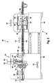
- Fig. 2 In the execution after Fig. 2 are the feed unit 16, the bending unit 32 and two NC measuring wheels 56, 58 combined to form a unit 90 which is adjustable in the longitudinal direction 52 and thus can change their position to the separation unit 44.
- the adjustment of the assembly 90 can be done manually. But it can also be adjusted by motor via a spindle drive, wherein the adjustment can be part of an automatic setup process.
- the NC measuring wheel 56 By the NC measuring wheel 56, the slip of the drawn and measured by the NC measuring wheel 58, the slip of the pushed spring steel strip 14.
- the measuring wheels 56, 58 detect the feed exactly, the second measuring wheel 58 monitoring the first measuring wheel 56 and the conveyor line lying between them. It is advantageous if the second measuring wheel 58 is mounted on the outside of the housing 54 of the separation unit 44.
- the upper bending roller 34 is mounted on a bending roller support 70, which can be adjusted by a bending motor 62 via a spindle 66.
- the return bending roller 36 is mounted on a bending roller support 68, wherein the bending roller support 68 is adjusted by a bending motor 60 via a spindle 64.
- the adjustment of these adjusting devices is very precise and almost free of play.
- the spring steel strip 14 is guided by a roller guide 74, the guide rollers can be pneumatically adjusted to the spring steel strip 14.
- the separation unit 44 after Fig. 2 is formed by a press the upper die 76 is mounted on an upper tool slide 80 which is slidably guided in a housing 54 of the separation unit 44 in the longitudinal direction 52 by means of slide guides 84, 86. Accordingly, a lower punching tool 78 is mounted on a lower tool slide 82, which in turn is slidably guided on a slide guide 86 in the longitudinal direction 52 in the housing 54. Since the guide rollers 50 in the area of the punching tools 76, 78 have to bridge a different guide path, depending on the position in which the punching tools 76, 78 are located, they can be telescoped apart, so depending on the position of the punching tools 76, 78 larger or set smaller distances between the guide rollers 50. The punching tools 76, 78, which act here as separating tools, can also interact with balancing masses.
- an ejector 88 which is driven and controlled by the electronic control unit 42. It detects the over the punching tools 76, 78 projecting end of the finished bent spring element and deposits it after separation into a reservoir.
Landscapes
- Engineering & Computer Science (AREA)
- Mechanical Engineering (AREA)
- Bending Of Plates, Rods, And Pipes (AREA)
- Wire Processing (AREA)
- Springs (AREA)
Priority Applications (1)
| Application Number | Priority Date | Filing Date | Title |
|---|---|---|---|
| PL06819577T PL1968757T3 (pl) | 2005-12-29 | 2006-11-17 | Sposób i urządzenie do wytwarzania wygiętych elementów sprężynowych |
Applications Claiming Priority (2)
| Application Number | Priority Date | Filing Date | Title |
|---|---|---|---|
| DE102005062860A DE102005062860A1 (de) | 2005-12-29 | 2005-12-29 | Verfahren und Vorrichtung zum Herstellen gebogener Federelemente |
| PCT/EP2006/068603 WO2007080023A1 (de) | 2005-12-29 | 2006-11-17 | Verfahren und vorrichtung zum herstellen gebogener federelemente |
Publications (2)
| Publication Number | Publication Date |
|---|---|
| EP1968757A1 EP1968757A1 (de) | 2008-09-17 |
| EP1968757B1 true EP1968757B1 (de) | 2010-03-17 |
Family
ID=37681369
Family Applications (1)
| Application Number | Title | Priority Date | Filing Date |
|---|---|---|---|
| EP06819577A Active EP1968757B1 (de) | 2005-12-29 | 2006-11-17 | Verfahren und vorrichtung zum herstellen gebogener federelemente |
Country Status (12)
| Country | Link |
|---|---|
| US (1) | US8333093B2 (pl) |
| EP (1) | EP1968757B1 (pl) |
| JP (1) | JP4903222B2 (pl) |
| KR (1) | KR101319956B1 (pl) |
| CN (1) | CN101351283B (pl) |
| AT (1) | ATE461000T1 (pl) |
| BR (1) | BRPI0620722A2 (pl) |
| DE (2) | DE102005062860A1 (pl) |
| ES (1) | ES2341365T3 (pl) |
| PL (1) | PL1968757T3 (pl) |
| RU (1) | RU2433009C2 (pl) |
| WO (1) | WO2007080023A1 (pl) |
Cited By (1)
| Publication number | Priority date | Publication date | Assignee | Title |
|---|---|---|---|---|
| CN102784851A (zh) * | 2012-07-18 | 2012-11-21 | 苏州瑞浦勒自动化系统有限公司 | 一种用于涡卷弹簧成型机的送料机构 |
Families Citing this family (37)
| Publication number | Priority date | Publication date | Assignee | Title |
|---|---|---|---|---|
| KR101075323B1 (ko) * | 2009-05-19 | 2011-10-19 | 대원강업주식회사 | 헬리코이드 리덕션 밀을 이용한 코일 스프링 제조방법 |
| DE102009036512B3 (de) * | 2009-08-07 | 2011-06-16 | Schomäcker Federnwerk GmbH | Verfahren und Vorrichtung zum Herstellen von Parabellenkern und Parabelfedern für insbesondere Fahrzeugchassis, Fahrzeugaufbauten und dgl. |
| CN101767267B (zh) * | 2010-03-03 | 2012-12-26 | 潮峰钢构集团有限公司 | 相贯线管件弯弧的加工工艺 |
| JP4708508B1 (ja) * | 2010-04-07 | 2011-06-22 | 株式会社太洋 | 全自動型パイプベンダー |
| DE102011000895A1 (de) * | 2011-02-23 | 2012-08-23 | Dr. Karl Bausch Gmbh & Co. Kg | Rückschluss, insbesondere für eine elektrische Maschine und Verfahren zur Herstellung eines Rückschlusses für einen Rotor oder Stator einer elektrischen Maschine |
| US9457768B2 (en) | 2011-04-21 | 2016-10-04 | Pylon Manufacturing Corp. | Vortex damping wiper blade |
| US9174611B2 (en) | 2011-07-28 | 2015-11-03 | Pylon Manufacturing Corp. | Windshield wiper adapter, connector and assembly |
| US9108595B2 (en) | 2011-07-29 | 2015-08-18 | Pylon Manufacturing Corporation | Windshield wiper connector |
| KR101286676B1 (ko) * | 2011-11-24 | 2013-07-16 | 주식회사 성우하이텍 | 롤 포밍 시스템용 전자기 성형장치 및 그 제어방법 |
| CN102528395B (zh) * | 2011-12-31 | 2013-09-11 | 天津重钢机械装备股份有限公司 | 由平面截切的矩形管道的成型方法 |
| US10723322B2 (en) | 2012-02-24 | 2020-07-28 | Pylon Manufacturing Corp. | Wiper blade with cover |
| MX364943B (es) | 2012-02-24 | 2019-05-14 | Pylon Mfg Corp | Escobilla limpiaparabrisas. |
| US20130219649A1 (en) | 2012-02-24 | 2013-08-29 | Pylon Manufacturing Corp. | Wiper blade |
| US10829092B2 (en) | 2012-09-24 | 2020-11-10 | Pylon Manufacturing Corp. | Wiper blade with modular mounting base |
| CN102962676B (zh) * | 2012-11-13 | 2015-03-25 | 北京时代民芯科技有限公司 | 一种SnPb焊柱的制备装置及方法 |
| US10166951B2 (en) | 2013-03-15 | 2019-01-01 | Pylon Manufacturing Corp. | Windshield wiper connector |
| US9505380B2 (en) | 2014-03-07 | 2016-11-29 | Pylon Manufacturing Corp. | Windshield wiper connector and assembly |
| CN104526355B (zh) * | 2014-11-14 | 2017-06-09 | 盐城旭华机械有限公司 | 罐体焊条切割装置 |
| CN104772374B (zh) * | 2015-05-09 | 2017-03-08 | 安徽水利开发股份有限公司 | W型金属止水带加工装置及w型金属止水带的加工方法 |
| WO2017075066A1 (en) | 2015-10-26 | 2017-05-04 | Pylon Manufacturing Corp. | Wiper blade |
| DE102016201460A1 (de) * | 2016-02-01 | 2017-08-03 | Robert Bosch Gmbh | Produktionsanlage mit transparenter Prozessregelung |
| WO2017201473A1 (en) | 2016-05-19 | 2017-11-23 | Pylon Manufacturing Corp. | Windshield wiper blade |
| CN109715449A (zh) | 2016-05-19 | 2019-05-03 | 电缆塔制造有限公司 | 挡风玻璃雨刮器连接器 |
| WO2017201485A1 (en) | 2016-05-19 | 2017-11-23 | Pylon Manufacturing Corp. | Windshield wiper connector |
| AU2017267978A1 (en) | 2016-05-19 | 2018-11-22 | Pylon Manufacturing Corp. | Windshield wiper connector |
| US11040705B2 (en) | 2016-05-19 | 2021-06-22 | Pylon Manufacturing Corp. | Windshield wiper connector |
| EP3593919B1 (en) * | 2018-07-09 | 2024-08-28 | Lapmaster Wolters GmbH | Fine blanking press and method for handling a process material to be processed in a fine blanking press |
| CN109719170A (zh) * | 2019-02-01 | 2019-05-07 | 王军 | 一种柔性板材卷曲成型模具设备 |
| CN111715781B (zh) * | 2019-03-18 | 2022-03-15 | 深圳市千业精密金属有限公司 | 一种弹簧成型工艺 |
| KR102218398B1 (ko) * | 2019-06-03 | 2021-02-19 | 주식회사 포스코 | 가변 굽힘 장치 |
| CN110695166B (zh) * | 2019-09-30 | 2025-07-04 | 洛阳方晨智能装备有限公司 | 一种钢板弹簧成型设备及其使用方法 |
| CN112058913B (zh) * | 2020-08-25 | 2025-12-19 | 河南凯银机械设备科技有限公司 | 汽车板簧热滚压成型机 |
| CN112296219B (zh) * | 2020-10-09 | 2022-12-16 | 深圳市天圆科技有限公司 | 一种二三极管芯片加工引脚切断装置 |
| US12447519B2 (en) * | 2020-12-17 | 2025-10-21 | Allor Manufacturing, Llc | Device and method for leveling a metal plate |
| CN113414278B (zh) * | 2021-07-15 | 2025-04-22 | 深圳吉阳智能科技有限公司 | 裁切装置 |
| CN113976770B (zh) * | 2021-10-19 | 2023-06-23 | 玉田县致泰钢纤维制造有限公司 | 一种复合型钢纤维剪切装置 |
| CN114178883A (zh) * | 2021-12-13 | 2022-03-15 | 苏州木渎特钢科技有限公司 | 一种毛细钢管生产用断线机 |
Family Cites Families (29)
| Publication number | Priority date | Publication date | Assignee | Title |
|---|---|---|---|---|
| JPS5219157A (en) | 1975-08-07 | 1977-02-14 | Ukishima Kouhan Kakou Kk | Bender table apparatus |
| SU602253A1 (ru) | 1976-02-11 | 1978-04-15 | Государственный Проектный Институт "Электротяжхимпроект" | Устройство управлени мерным резом полос с периодически повтор ющимис гофрами |
| US4249406A (en) | 1978-09-05 | 1981-02-10 | Anderson Frohman C | Line pipe forming apparatus and method |
| JPS55153700A (en) | 1979-05-17 | 1980-11-29 | Aisin Seiki Co Ltd | Synchronously traveling reciprocative working device |
| JPS5837093B2 (ja) * | 1980-12-23 | 1983-08-13 | 株式会社 ブレスト工業研究所 | 走間剪断機 |
| JPS6178518A (ja) | 1984-09-21 | 1986-04-22 | Sumitomo Metal Mining Co Ltd | ロ−ル成形機のロ−ル調整装置 |
| JPS6234716A (ja) * | 1985-08-02 | 1987-02-14 | Nasuko Kk | 走間加工機 |
| JPS6274523A (ja) | 1985-09-25 | 1987-04-06 | Nippon Denso Co Ltd | 高速切断機 |
| JPS62134613A (ja) | 1985-12-07 | 1987-06-17 | Olympus Optical Co Ltd | グレ−テイング保持機構 |
| US4770796A (en) | 1987-01-12 | 1988-09-13 | Petrolite Corporation | Encapsulated breaker for cross-linked acid gel, fracture acidizing fluid containing same and method of use thereof |
| ATE82882T1 (de) * | 1987-09-12 | 1992-12-15 | Hamburger Stahlwerke Gmbh | Drahtwalzwerk. |
| US5063801A (en) * | 1989-01-23 | 1991-11-12 | Wallis Bernard J | Cut-off machine and method for tubing |
| SU1680406A1 (ru) * | 1989-06-27 | 1991-09-30 | Государственный Проектный И Проектно-Конструкторский Институт "Электротяжхимпроект" | Способ управлени станом с перфорацией и порезкой гнутых профилей на ходу и устройство дл его осуществлени |
| JPH0675736B2 (ja) * | 1990-02-21 | 1994-09-28 | アイセル株式会社 | 筒体製造装置 |
| JPH0675736A (ja) | 1992-08-25 | 1994-03-18 | Fujitsu Ltd | 情報処理装置の表示制御方式及び表示制御方法 |
| JPH07171628A (ja) | 1993-12-20 | 1995-07-11 | Kanai Hiroyuki | 平板の円筒形ワーク成形方法 |
| JPH07185671A (ja) * | 1993-12-27 | 1995-07-25 | Daido Kikai Seisakusho:Kk | ロールベンダー |
| JPH1110241A (ja) | 1997-06-23 | 1999-01-19 | Kanzaki Kogyo Kk | 形鋼屈曲装置 |
| US6134999A (en) * | 1997-08-15 | 2000-10-24 | Heidelberg Druckmaschinen Ag | Trimming device for flat articles |
| JPH11169955A (ja) | 1997-12-10 | 1999-06-29 | Chiyoda:Kk | 帯刃曲げ装置 |
| US7076979B2 (en) * | 1998-04-07 | 2006-07-18 | Robert Bosch Gmbh | Method and device for producing curved lengths of spring band steel |
| DE19816609A1 (de) | 1998-04-15 | 1999-10-21 | Bosch Gmbh Robert | Verfahren zum Herstellen von Flachbalken-Scheibenwischern für Fahrzeuge mit gebogenen Flachbalken |
| US6229674B1 (en) * | 1999-07-29 | 2001-05-08 | Storage Technology Corporation | Coarse and fine positioning device employing a single driving mechanism |
| JP4225658B2 (ja) | 1999-12-09 | 2009-02-18 | 奥田 保幸 | 金属製波形管製造装置及び金属製波形製品の製造方法 |
| DE10115047B4 (de) * | 2001-03-27 | 2010-01-28 | Robert Bosch Gmbh | Verfahren und Vorrichtung zum Herstellen gebogener Federbandabschnitte |
| DE10120050C1 (de) | 2001-04-24 | 2002-10-10 | Valeo Auto Electric Gmbh | Verfahren und Vorrichtung zum Herstellen gebogener Federbandabschnitte |
| JP2003211227A (ja) | 2001-11-14 | 2003-07-29 | Isel Co Ltd | ロール曲げ装置 |
| BR0311543B1 (pt) * | 2002-06-03 | 2011-10-04 | método e aparelho para redução do diámetro de uma parede lateral de um corpo de container de metal. | |
| WO2004110667A1 (de) * | 2003-06-13 | 2004-12-23 | Adval Tech Holding Ag | Transfervorrichtung an einer presse |
-
2005
- 2005-12-29 DE DE102005062860A patent/DE102005062860A1/de not_active Withdrawn
-
2006
- 2006-11-17 JP JP2008547920A patent/JP4903222B2/ja not_active Expired - Fee Related
- 2006-11-17 AT AT06819577T patent/ATE461000T1/de active
- 2006-11-17 US US12/159,052 patent/US8333093B2/en not_active Expired - Fee Related
- 2006-11-17 EP EP06819577A patent/EP1968757B1/de active Active
- 2006-11-17 KR KR1020087014345A patent/KR101319956B1/ko not_active Expired - Fee Related
- 2006-11-17 RU RU2008130923/02A patent/RU2433009C2/ru not_active IP Right Cessation
- 2006-11-17 WO PCT/EP2006/068603 patent/WO2007080023A1/de not_active Ceased
- 2006-11-17 PL PL06819577T patent/PL1968757T3/pl unknown
- 2006-11-17 DE DE502006006475T patent/DE502006006475D1/de active Active
- 2006-11-17 ES ES06819577T patent/ES2341365T3/es active Active
- 2006-11-17 CN CN2006800499314A patent/CN101351283B/zh active Active
- 2006-11-17 BR BRPI0620722-7A patent/BRPI0620722A2/pt not_active IP Right Cessation
Cited By (1)
| Publication number | Priority date | Publication date | Assignee | Title |
|---|---|---|---|---|
| CN102784851A (zh) * | 2012-07-18 | 2012-11-21 | 苏州瑞浦勒自动化系统有限公司 | 一种用于涡卷弹簧成型机的送料机构 |
Also Published As
| Publication number | Publication date |
|---|---|
| ATE461000T1 (de) | 2010-04-15 |
| EP1968757A1 (de) | 2008-09-17 |
| JP2009522105A (ja) | 2009-06-11 |
| CN101351283A (zh) | 2009-01-21 |
| RU2433009C2 (ru) | 2011-11-10 |
| DE502006006475D1 (de) | 2010-04-29 |
| JP4903222B2 (ja) | 2012-03-28 |
| ES2341365T3 (es) | 2010-06-18 |
| BRPI0620722A2 (pt) | 2011-11-22 |
| WO2007080023A1 (de) | 2007-07-19 |
| PL1968757T3 (pl) | 2010-07-30 |
| CN101351283B (zh) | 2013-05-01 |
| RU2008130923A (ru) | 2010-02-10 |
| US8333093B2 (en) | 2012-12-18 |
| KR101319956B1 (ko) | 2013-10-29 |
| US20080302157A1 (en) | 2008-12-11 |
| DE102005062860A1 (de) | 2007-07-12 |
| KR20080081923A (ko) | 2008-09-10 |
Similar Documents
| Publication | Publication Date | Title |
|---|---|---|
| EP1968757B1 (de) | Verfahren und vorrichtung zum herstellen gebogener federelemente | |
| DE69404473T2 (de) | Maschine zum herstellen von rohren aus pappe oder ähnlichem material, mit einer vorrichtung zum in stücke schneiden von rohren mit vorbestimmten längen | |
| DE69420707T2 (de) | Herstellung von metallischem band | |
| EP3673570B1 (de) | Fertigungsanlage zum herstellen eines wicklungsstabes für einen elektromotor, sowie verfahren zum herstellen des wicklungsstabes | |
| DE69103033T2 (de) | Verfahren und Vorrichtung zum Schneiden von Rohren. | |
| EP2505269A2 (de) | Vorrichtung zum Beleimen eines bewegten Umhüllungsstreifens für stabförmige Produkte der Tabak verarbeitenden Industrie und Anlage mit einer derartigen Vorrichtung | |
| EP3235388B1 (de) | Vorrichtung zum auftragen einer leimspur auf einen umhüllungsstreifen eines stabförmigen produktes der tabak verarbeitenden industrie | |
| EP2497582B1 (de) | Rollenumformeinrichtung zum Umformen eines bandförmigen Metallmaterials | |
| EP2510791A2 (de) | Vorrichtung zur Formung eines Teigbandes aus zugeführten Teigportionen | |
| EP0988195B1 (de) | Verfahren zum herstellen von flachbalken-scheibenwischern für fahrzeuge mit gebogenen flachbalken | |
| EP3572161B1 (de) | Verfahren und vorrichtung zur herstellung eines produkts aus flexibel gewalztem bandmaterial | |
| DE2838128A1 (de) | Vorrichtung zum herstellen von ringen | |
| DE3028834A1 (de) | Verfahren und maschine zum automatischen stanzen und biegen von werkstuecken | |
| EP2401928A2 (de) | Einrichtung zur Herstellung von stabförmigen Produkten der Tabak verarbeitenden Industrie | |
| EP1069963B1 (de) | Verfahren und vorrichtung zum herstellen gebogener federbandabschnitte | |
| EP3826781B1 (de) | Verfahren und vorrichtung zur ermittlung der seitlichen bandkontur oder der position der bandkanten eines laufenden metallbandes | |
| EP1786577B1 (de) | Verfahren zum walzen eines metallbands | |
| EP1011908A1 (de) | Vorrichtung zur herstellung von bandsägeblättern | |
| EP1347849A1 (de) | Drückwalzverfahren und vorrichtung zum drückwalzen | |
| DE102004051454B4 (de) | Verfahren und Vorrichtung zur Herstellung eines Profils | |
| EP0800885A2 (de) | Vorrichtung zum Herausstanzen von Sägezähnen aus einem Bandmaterial | |
| EP2299042B1 (de) | Gießanlage für thermisch getrennte Metallprofile | |
| WO2025087749A1 (de) | Verfahren und umformmaschine zur herstellung von formteilen | |
| DE102006014304A1 (de) | Verfahren und Vorrichtung zum Verformen einer mit mindestens einer Markierung versehenen Folie | |
| DE1198502B (de) | Einrichtung zur maschinellen Erzeugung von Glasplaettchen |
Legal Events
| Date | Code | Title | Description |
|---|---|---|---|
| PUAI | Public reference made under article 153(3) epc to a published international application that has entered the european phase |
Free format text: ORIGINAL CODE: 0009012 |
|
| 17P | Request for examination filed |
Effective date: 20080729 |
|
| AK | Designated contracting states |
Kind code of ref document: A1 Designated state(s): AT BE BG CH CY CZ DE DK EE ES FI FR GB GR HU IE IS IT LI LT LU LV MC NL PL PT RO SE SI SK TR |
|
| 17Q | First examination report despatched |
Effective date: 20081208 |
|
| GRAP | Despatch of communication of intention to grant a patent |
Free format text: ORIGINAL CODE: EPIDOSNIGR1 |
|
| GRAS | Grant fee paid |
Free format text: ORIGINAL CODE: EPIDOSNIGR3 |
|
| GRAA | (expected) grant |
Free format text: ORIGINAL CODE: 0009210 |
|
| AK | Designated contracting states |
Kind code of ref document: B1 Designated state(s): AT BE BG CH CY CZ DE DK EE ES FI FR GB GR HU IE IS IT LI LT LU LV MC NL PL PT RO SE SI SK TR |
|
| REG | Reference to a national code |
Ref country code: GB Ref legal event code: FG4D Free format text: NOT ENGLISH |
|
| REG | Reference to a national code |
Ref country code: CH Ref legal event code: EP |
|
| REG | Reference to a national code |
Ref country code: IE Ref legal event code: FG4D |
|
| REF | Corresponds to: |
Ref document number: 502006006475 Country of ref document: DE Date of ref document: 20100429 Kind code of ref document: P |
|
| REG | Reference to a national code |
Ref country code: ES Ref legal event code: FG2A Ref document number: 2341365 Country of ref document: ES Kind code of ref document: T3 |
|
| REG | Reference to a national code |
Ref country code: NL Ref legal event code: VDEP Effective date: 20100317 |
|
| PG25 | Lapsed in a contracting state [announced via postgrant information from national office to epo] |
Ref country code: LT Free format text: LAPSE BECAUSE OF FAILURE TO SUBMIT A TRANSLATION OF THE DESCRIPTION OR TO PAY THE FEE WITHIN THE PRESCRIBED TIME-LIMIT Effective date: 20100317 |
|
| REG | Reference to a national code |
Ref country code: PL Ref legal event code: T3 |
|
| LTIE | Lt: invalidation of european patent or patent extension |
Effective date: 20100317 |
|
| PG25 | Lapsed in a contracting state [announced via postgrant information from national office to epo] |
Ref country code: LV Free format text: LAPSE BECAUSE OF FAILURE TO SUBMIT A TRANSLATION OF THE DESCRIPTION OR TO PAY THE FEE WITHIN THE PRESCRIBED TIME-LIMIT Effective date: 20100317 Ref country code: SI Free format text: LAPSE BECAUSE OF FAILURE TO SUBMIT A TRANSLATION OF THE DESCRIPTION OR TO PAY THE FEE WITHIN THE PRESCRIBED TIME-LIMIT Effective date: 20100317 Ref country code: FI Free format text: LAPSE BECAUSE OF FAILURE TO SUBMIT A TRANSLATION OF THE DESCRIPTION OR TO PAY THE FEE WITHIN THE PRESCRIBED TIME-LIMIT Effective date: 20100317 |
|
| REG | Reference to a national code |
Ref country code: IE Ref legal event code: FD4D |
|
| REG | Reference to a national code |
Ref country code: HU Ref legal event code: AG4A Ref document number: E008204 Country of ref document: HU |
|
| PG25 | Lapsed in a contracting state [announced via postgrant information from national office to epo] |
Ref country code: RO Free format text: LAPSE BECAUSE OF FAILURE TO SUBMIT A TRANSLATION OF THE DESCRIPTION OR TO PAY THE FEE WITHIN THE PRESCRIBED TIME-LIMIT Effective date: 20100317 Ref country code: GR Free format text: LAPSE BECAUSE OF FAILURE TO SUBMIT A TRANSLATION OF THE DESCRIPTION OR TO PAY THE FEE WITHIN THE PRESCRIBED TIME-LIMIT Effective date: 20100618 Ref country code: CY Free format text: LAPSE BECAUSE OF FAILURE TO SUBMIT A TRANSLATION OF THE DESCRIPTION OR TO PAY THE FEE WITHIN THE PRESCRIBED TIME-LIMIT Effective date: 20100317 Ref country code: SE Free format text: LAPSE BECAUSE OF FAILURE TO SUBMIT A TRANSLATION OF THE DESCRIPTION OR TO PAY THE FEE WITHIN THE PRESCRIBED TIME-LIMIT Effective date: 20100317 Ref country code: NL Free format text: LAPSE BECAUSE OF FAILURE TO SUBMIT A TRANSLATION OF THE DESCRIPTION OR TO PAY THE FEE WITHIN THE PRESCRIBED TIME-LIMIT Effective date: 20100317 Ref country code: EE Free format text: LAPSE BECAUSE OF FAILURE TO SUBMIT A TRANSLATION OF THE DESCRIPTION OR TO PAY THE FEE WITHIN THE PRESCRIBED TIME-LIMIT Effective date: 20100317 |
|
| PG25 | Lapsed in a contracting state [announced via postgrant information from national office to epo] |
Ref country code: BG Free format text: LAPSE BECAUSE OF FAILURE TO SUBMIT A TRANSLATION OF THE DESCRIPTION OR TO PAY THE FEE WITHIN THE PRESCRIBED TIME-LIMIT Effective date: 20100617 Ref country code: IS Free format text: LAPSE BECAUSE OF FAILURE TO SUBMIT A TRANSLATION OF THE DESCRIPTION OR TO PAY THE FEE WITHIN THE PRESCRIBED TIME-LIMIT Effective date: 20100717 Ref country code: SK Free format text: LAPSE BECAUSE OF FAILURE TO SUBMIT A TRANSLATION OF THE DESCRIPTION OR TO PAY THE FEE WITHIN THE PRESCRIBED TIME-LIMIT Effective date: 20100317 |
|
| PLBE | No opposition filed within time limit |
Free format text: ORIGINAL CODE: 0009261 |
|
| STAA | Information on the status of an ep patent application or granted ep patent |
Free format text: STATUS: NO OPPOSITION FILED WITHIN TIME LIMIT |
|
| PG25 | Lapsed in a contracting state [announced via postgrant information from national office to epo] |
Ref country code: PT Free format text: LAPSE BECAUSE OF FAILURE TO SUBMIT A TRANSLATION OF THE DESCRIPTION OR TO PAY THE FEE WITHIN THE PRESCRIBED TIME-LIMIT Effective date: 20100719 Ref country code: IE Free format text: LAPSE BECAUSE OF FAILURE TO SUBMIT A TRANSLATION OF THE DESCRIPTION OR TO PAY THE FEE WITHIN THE PRESCRIBED TIME-LIMIT Effective date: 20100317 Ref country code: DK Free format text: LAPSE BECAUSE OF FAILURE TO SUBMIT A TRANSLATION OF THE DESCRIPTION OR TO PAY THE FEE WITHIN THE PRESCRIBED TIME-LIMIT Effective date: 20100317 |
|
| 26N | No opposition filed |
Effective date: 20101220 |
|
| PG25 | Lapsed in a contracting state [announced via postgrant information from national office to epo] |
Ref country code: IT Free format text: LAPSE BECAUSE OF FAILURE TO SUBMIT A TRANSLATION OF THE DESCRIPTION OR TO PAY THE FEE WITHIN THE PRESCRIBED TIME-LIMIT Effective date: 20100317 |
|
| PG25 | Lapsed in a contracting state [announced via postgrant information from national office to epo] |
Ref country code: MC Free format text: LAPSE BECAUSE OF NON-PAYMENT OF DUE FEES Effective date: 20101130 |
|
| REG | Reference to a national code |
Ref country code: CH Ref legal event code: PL |
|
| PG25 | Lapsed in a contracting state [announced via postgrant information from national office to epo] |
Ref country code: CH Free format text: LAPSE BECAUSE OF NON-PAYMENT OF DUE FEES Effective date: 20101130 Ref country code: LI Free format text: LAPSE BECAUSE OF NON-PAYMENT OF DUE FEES Effective date: 20101130 |
|
| PG25 | Lapsed in a contracting state [announced via postgrant information from national office to epo] |
Ref country code: LU Free format text: LAPSE BECAUSE OF NON-PAYMENT OF DUE FEES Effective date: 20101117 |
|
| PG25 | Lapsed in a contracting state [announced via postgrant information from national office to epo] |
Ref country code: TR Free format text: LAPSE BECAUSE OF FAILURE TO SUBMIT A TRANSLATION OF THE DESCRIPTION OR TO PAY THE FEE WITHIN THE PRESCRIBED TIME-LIMIT Effective date: 20100317 |
|
| REG | Reference to a national code |
Ref country code: AT Ref legal event code: MM01 Ref document number: 461000 Country of ref document: AT Kind code of ref document: T Effective date: 20111117 |
|
| PG25 | Lapsed in a contracting state [announced via postgrant information from national office to epo] |
Ref country code: AT Free format text: LAPSE BECAUSE OF NON-PAYMENT OF DUE FEES Effective date: 20111117 |
|
| REG | Reference to a national code |
Ref country code: FR Ref legal event code: PLFP Year of fee payment: 10 |
|
| PGFP | Annual fee paid to national office [announced via postgrant information from national office to epo] |
Ref country code: GB Payment date: 20151123 Year of fee payment: 10 |
|
| PGFP | Annual fee paid to national office [announced via postgrant information from national office to epo] |
Ref country code: PL Payment date: 20151105 Year of fee payment: 10 Ref country code: ES Payment date: 20151124 Year of fee payment: 10 |
|
| REG | Reference to a national code |
Ref country code: FR Ref legal event code: PLFP Year of fee payment: 11 |
|
| GBPC | Gb: european patent ceased through non-payment of renewal fee |
Effective date: 20161117 |
|
| REG | Reference to a national code |
Ref country code: FR Ref legal event code: PLFP Year of fee payment: 12 |
|
| PG25 | Lapsed in a contracting state [announced via postgrant information from national office to epo] |
Ref country code: GB Free format text: LAPSE BECAUSE OF NON-PAYMENT OF DUE FEES Effective date: 20161117 |
|
| PG25 | Lapsed in a contracting state [announced via postgrant information from national office to epo] |
Ref country code: PL Free format text: LAPSE BECAUSE OF NON-PAYMENT OF DUE FEES Effective date: 20161117 |
|
| PG25 | Lapsed in a contracting state [announced via postgrant information from national office to epo] |
Ref country code: ES Free format text: LAPSE BECAUSE OF NON-PAYMENT OF DUE FEES Effective date: 20161118 |
|
| REG | Reference to a national code |
Ref country code: ES Ref legal event code: FD2A Effective date: 20181123 |
|
| PGFP | Annual fee paid to national office [announced via postgrant information from national office to epo] |
Ref country code: HU Payment date: 20191104 Year of fee payment: 14 Ref country code: CZ Payment date: 20191105 Year of fee payment: 14 |
|
| PG25 | Lapsed in a contracting state [announced via postgrant information from national office to epo] |
Ref country code: CZ Free format text: LAPSE BECAUSE OF NON-PAYMENT OF DUE FEES Effective date: 20201117 |
|
| PG25 | Lapsed in a contracting state [announced via postgrant information from national office to epo] |
Ref country code: HU Free format text: LAPSE BECAUSE OF NON-PAYMENT OF DUE FEES Effective date: 20201118 |
|
| PGFP | Annual fee paid to national office [announced via postgrant information from national office to epo] |
Ref country code: DE Payment date: 20250122 Year of fee payment: 19 |
|
| PGFP | Annual fee paid to national office [announced via postgrant information from national office to epo] |
Ref country code: FR Payment date: 20251120 Year of fee payment: 20 |
|
| PGFP | Annual fee paid to national office [announced via postgrant information from national office to epo] |
Ref country code: BE Payment date: 20251118 Year of fee payment: 20 |