EP1967703B1 - Verriegelungsarm, verriegelungsbolzen, ventilkappe, einstellschraube, gelenkaufnahmeglied und ventil einer armartigen ventilbetriebsvorrichtung - Google Patents
Verriegelungsarm, verriegelungsbolzen, ventilkappe, einstellschraube, gelenkaufnahmeglied und ventil einer armartigen ventilbetriebsvorrichtung Download PDFInfo
- Publication number
- EP1967703B1 EP1967703B1 EP06843218A EP06843218A EP1967703B1 EP 1967703 B1 EP1967703 B1 EP 1967703B1 EP 06843218 A EP06843218 A EP 06843218A EP 06843218 A EP06843218 A EP 06843218A EP 1967703 B1 EP1967703 B1 EP 1967703B1
- Authority
- EP
- European Patent Office
- Prior art keywords
- valve
- recesses
- rocker arm
- contact
- arm
- Prior art date
- Legal status (The legal status is an assumption and is not a legal conclusion. Google has not performed a legal analysis and makes no representation as to the accuracy of the status listed.)
- Not-in-force
Links
Images


Classifications
-
- F—MECHANICAL ENGINEERING; LIGHTING; HEATING; WEAPONS; BLASTING
- F01—MACHINES OR ENGINES IN GENERAL; ENGINE PLANTS IN GENERAL; STEAM ENGINES
- F01L—CYCLICALLY OPERATING VALVES FOR MACHINES OR ENGINES
- F01L1/00—Valve-gear or valve arrangements, e.g. lift-valve gear
- F01L1/12—Transmitting gear between valve drive and valve
- F01L1/18—Rocking arms or levers
- F01L1/185—Overhead end-pivot rocking arms
-
- F—MECHANICAL ENGINEERING; LIGHTING; HEATING; WEAPONS; BLASTING
- F01—MACHINES OR ENGINES IN GENERAL; ENGINE PLANTS IN GENERAL; STEAM ENGINES
- F01L—CYCLICALLY OPERATING VALVES FOR MACHINES OR ENGINES
- F01L1/00—Valve-gear or valve arrangements, e.g. lift-valve gear
- F01L1/12—Transmitting gear between valve drive and valve
- F01L1/18—Rocking arms or levers
- F01L1/181—Centre pivot rocking arms
-
- F—MECHANICAL ENGINEERING; LIGHTING; HEATING; WEAPONS; BLASTING
- F01—MACHINES OR ENGINES IN GENERAL; ENGINE PLANTS IN GENERAL; STEAM ENGINES
- F01L—CYCLICALLY OPERATING VALVES FOR MACHINES OR ENGINES
- F01L1/00—Valve-gear or valve arrangements, e.g. lift-valve gear
- F01L1/12—Transmitting gear between valve drive and valve
- F01L1/14—Tappets; Push rods
- F01L1/16—Silencing impact; Reducing wear
-
- F—MECHANICAL ENGINEERING; LIGHTING; HEATING; WEAPONS; BLASTING
- F01—MACHINES OR ENGINES IN GENERAL; ENGINE PLANTS IN GENERAL; STEAM ENGINES
- F01L—CYCLICALLY OPERATING VALVES FOR MACHINES OR ENGINES
- F01L1/00—Valve-gear or valve arrangements, e.g. lift-valve gear
- F01L1/20—Adjusting or compensating clearance
-
- F—MECHANICAL ENGINEERING; LIGHTING; HEATING; WEAPONS; BLASTING
- F01—MACHINES OR ENGINES IN GENERAL; ENGINE PLANTS IN GENERAL; STEAM ENGINES
- F01L—CYCLICALLY OPERATING VALVES FOR MACHINES OR ENGINES
- F01L2303/00—Manufacturing of components used in valve arrangements
-
- F—MECHANICAL ENGINEERING; LIGHTING; HEATING; WEAPONS; BLASTING
- F01—MACHINES OR ENGINES IN GENERAL; ENGINE PLANTS IN GENERAL; STEAM ENGINES
- F01L—CYCLICALLY OPERATING VALVES FOR MACHINES OR ENGINES
- F01L2305/00—Valve arrangements comprising rollers
-
- F—MECHANICAL ENGINEERING; LIGHTING; HEATING; WEAPONS; BLASTING
- F01—MACHINES OR ENGINES IN GENERAL; ENGINE PLANTS IN GENERAL; STEAM ENGINES
- F01L—CYCLICALLY OPERATING VALVES FOR MACHINES OR ENGINES
- F01L2800/00—Methods of operation using a variable valve timing mechanism
- F01L2800/18—Testing or simulation
-
- F—MECHANICAL ENGINEERING; LIGHTING; HEATING; WEAPONS; BLASTING
- F01—MACHINES OR ENGINES IN GENERAL; ENGINE PLANTS IN GENERAL; STEAM ENGINES
- F01L—CYCLICALLY OPERATING VALVES FOR MACHINES OR ENGINES
- F01L2820/00—Details on specific features characterising valve gear arrangements
- F01L2820/01—Absolute values
-
- F—MECHANICAL ENGINEERING; LIGHTING; HEATING; WEAPONS; BLASTING
- F16—ENGINEERING ELEMENTS AND UNITS; GENERAL MEASURES FOR PRODUCING AND MAINTAINING EFFECTIVE FUNCTIONING OF MACHINES OR INSTALLATIONS; THERMAL INSULATION IN GENERAL
- F16C—SHAFTS; FLEXIBLE SHAFTS; ELEMENTS OR CRANKSHAFT MECHANISMS; ROTARY BODIES OTHER THAN GEARING ELEMENTS; BEARINGS
- F16C2240/00—Specified values or numerical ranges of parameters; Relations between them
- F16C2240/40—Linear dimensions, e.g. length, radius, thickness, gap
- F16C2240/54—Surface roughness
Definitions
- the present invention relates to a rocker arm, a rocker shaft, a valve cap, an adjust screw, a pivot receiving member, and a valve of an arm type valve operating device.
- An arm type valve operating device using a rocker arm opening and closing an intake valve or an exhaust valve through rotation of a cam is of two types: an end pivot type in which a cam shaft is arranged above a swingably-supported rocker arm, and a center pivot type in which a cam shaft is arranged below a rocker arm.
- the rocker arm In the end pivot type, the rocker arm is pushed down by a cam provided on the cam shaft to open the valve; and, in the center pivot type, one end portion of the rocker arm is pushed up by a cam provided on the cam shaft to open the valve with the other end portion of the rocker arm.
- the rocker arm in the center pivot type, is pivoted to the rocker shaft, and is swingable around the rocker shaft axis.
- the rocker arm and the rocker shaft are in sliding contact with each other.
- Patent Document 1 lubricant oil is supplied to the sliding portions between the rocker arm and the rocker shaft.
- a valve cap coming into contact with the rocker arm may be arranged at the forward end of the valve stem portion of the valve. It is necessary for such a valve cap to be superior in durability. Thus, in a related-art technology, an attempt is made to achieve an improvement in durability (Patent Document 2).
- An adjust screw is disposed adjacent to the rocker arm; in the center pivot type, the adjust screw is held in sliding contact with a valve; in the end pivot type, it is held in sliding contact with a pivot receiving member. Thus, it is desirable for the contact surfaces not to be worn.
- a lubricant member is provided in an engagement portion between a screw and a socket receiving the same (Patent Document 3).
- Patent Document 3 engine oil, for example, is used for the lubricant member, and the engagement portion of the screw and the socket is filled with oil.
- Patent Document 3 further discloses use of alloy steel that has undergone surface-hardening treatment for one of the screw and the socket.
- Patent Document 4 In the case of the end pivot type, the valve receiving portion of the rocker arm and the valve are in sliding contact with each other, so the valve receiving portion must be superior in durability. In view of this, in a related-art technology, an attempt is made to achieve an improvement in durability (Patent Document 4).
- a diamond-like carbon film is formed on the portion thereof coming into contact with the valve.
- the surface roughness Ry (maximumheight in ⁇ m) of the diamond-like carbon film is 3.2 or less, and the thickness of the diamond-like carbon film ranges from 1.0 to 5.0 ⁇ m, with the adhesion property being 40 N or more.
- the rocker arm preferentially supplies lubricant oil to the sliding portion between itself and the rocker shaft, so it is necessary to provide an oil escape passage and a valve device arranged in the oil escape passage, resulting in a rather complicated construction. Further, when there is a shortage of lubricant oil, wear and pitching occur in the contact portions.
- valve cap comes into contact with the rocker arm instead of the forward end of the valve stem portion, so wear and pitching are likely to occur due to sliding contact; thus, even when, as in Patent Document 2, the abutment portion of the valve cap is shifted little by little each time press contact is effected, or a high speed tool steel material or the like is used, lubricant oil is not supplied in a sufficient amount, so in some cases it is impossible to sufficiently suppress wear and pitching.
- valve receiving portion is subject to wear and pitching, and a sufficient amount of lubricant oil is not supplied even when a diamond-like carbon film is formed as described in Patent Document 4, so there are cases in which wear and pitching cannot be sufficiently suppressed.
- the rocker arm of the present invention is characterized by including a rocker arm for opening and closing a valve, including: a multiplicity of minute recesses provided at random at least in a contact portion coming into contact with a rocker shaft; and a surface with the recesses having a surface roughness parameter Ryni that is in a range: 0.4 ⁇ m ⁇ Ryni ⁇ 1.0 ⁇ m, and an Sk value of -1.6 or less.
- the rocker shaft of the present invention is characterized by including a rocker shaft which supports a rocker arm for opening and closing a valve, including: the multiplicity of minute recesses provided at random at least in a contact portion coming into contact with the rocker arm; and a surface with the recesses having a surface roughness parameter Ryni that is in a range: 0.4 ⁇ m ⁇ Ryni ⁇ 1.0 ⁇ m, and an Sk value of -1.6 or less.
- valve cap of the present invention is characterized by including a valve cap arranged at a forward end of a valve and abutting a rocker arm, including: the multiplicity of minute recesses provided at random at least in one of a contact portion coming into contact with the valve and a contact portion coming into contact with the rocker arm; and a surface with the recesses having a surface roughness parameter Ryni that is in a range: 0.4 ⁇ m ⁇ Ryni ⁇ 1.0 ⁇ m, and an Sk value of -1.6 or less.
- the adjust screw of the present invention is characterized by including an adjust screw attached to a rocker arm for opening and closing a valve, including the multiplicity of minute recesses provided at random at least in a contact surface coming into contact with another member, in which the surface with the recesses has a surface roughness parameter Ryni that is in a range: 0.4 ⁇ m ⁇ Ryni ⁇ 1.0 ⁇ m, and an Sk value of -1.6 or less.
- the term "another member” herein refers to the valve or the pivot receiving member.
- the pivot receiving member of the present invention is characterized by including a pivot receiving member receiving an adjust screw attached to a rocker arm for opening and closing a valve, including the multiplicity of minute recesses provided at random in a contact surface coming into contact with the adjust screw, in which the surface with the recesses has a surface roughness parameter Ryni that is in a range: 0.4 ⁇ m ⁇ Ryni ⁇ 1.0 ⁇ m, and an Sk value of -1.6 or less.
- the rocker arm of an arm type valve operating device of the present invention is characterized by including a rocker arm of an arm type valve operating device receiving a forward end portion of a valve by a valve receiving portion, including the multiplicity of minute recesses provided at random at least in a receiving surface of the valve receiving portion, in which the surface with the recesses has a surface roughness parameter Ryni that is in a range: 0.4 ⁇ m ⁇ Ryni ⁇ 1.0 ⁇ m, and an Sk value of -1.6 or less.
- valve of an arm type valve operating device of the present invention is characterized by including a valve of an arm type valve operating device whose forward end portion comes into contact with a rocker arm, including the multiplicity of minute recesses provided at random at least in an arm contact surface of the forward end portion, in which the surface provided with the recesses has a surface roughness parameter Ryni that is in a range: 0.4 ⁇ m ⁇ Ryni ⁇ 1.0 ⁇ m, and an Sk value of -1.6 or less.
- the parameter Ryni refers to an average value of reference length maximum height, that is, a value obtained by extracting a reference length of the roughness curve in the average line direction and measuring the distance between the crest line and the trough line of this extracted portion in the direction of longitudinal magnification of the roughness curve (ISO 4287:1997).
- the parameter Sk refers to the degree of distortion (skewness) of the roughness curve (ISO 4287:1997) ; it is a statistic amount indicating asymmetric diversity in protrusion/recess distribution. In a symmetrical distribution like Gaussian distribution, the Sk value is close to zero; when the protrusions are removed from the protrusions and recesses, it assumes a negative value, and, in the reverse case, it assumes a positive value.
- the surface roughness parameter Ryni of the surface with recesses is set within the range: 0.4 ⁇ m ⁇ Ryni ⁇ 1.0 ⁇ m, whereby it is possible to prevent depletion of oil film even under a condition of thin lubrication, thereby enabling to attain a long service life even when the oil film thickness is extremely small.
- the Sk value of the contact surface is set to -1.6 or less in both the width direction and the circumferential direction, the minute recesses constitute oil sumps, and, even when compressed, little oil leakage is involved in the slipping direction and the right-angle direction, thereby attaining superior oil film formation property and minimizing surface damage.
- the rocker arm of the present invention is characterized by including a rocker arm for opening and closing a valve, including the multiplicity of minute recesses provided at random at least in a contact portion coming into contact with the rocker shaft, in which an average area of the recesses of the surface provided with the recesses ranges from 30 to 100 ⁇ m 2 , and in which the surface provided with the recesses has a surface roughness parameter Rymax ranging from 0.4 to 1.0 ⁇ m.
- the rocker shaft of the present invention is characterized by including a rocker shaft which supports a rocker arm for opening and closing a valve, including the multiplicity of minute recesses provided at random at least in a contact portion coming into contact with the rocker arm, in which an average area of the recesses of the surface provided with the recesses ranges from 30 to 100 ⁇ m 2 , and in which the surface provided with the recesses has a surface roughness parameter Rymax ranging from 0.4 to 1.0 ⁇ m.
- valve cap of the present invention is characterized by including a valve cap arranged at a forward end of a valve and abutting a rocker arm, including the multiplicity of minute recesses provided at random at least in one of a contact portion coming into contact with the valve and a contact portion coming into contact with the rocker arm, in which an average area of the recesses ranges from 30 to 100 ⁇ m 2 , and in which Rymax ranges from 0.4 to 1.0 ⁇ m.
- the adjust screw of the present invention is characterized by including an adjust screw attached to a rocker arm for opening and closing a valve, including the multiplicity of minute recesses provided at random at least in a contact surface coming into contact with another member, in which an average area of the recesses of the surface provided with the recesses ranges from 30 to 100 ⁇ m 2 , and in which the surface provided with the recesses has a surface roughness parameter Rymax ranging from 0.4 to 1.0 ⁇ m.
- the term "another member” herein also refers to the valve or the pivot receiving member.
- the pivot receiving member of the present invention is characterized by including a pivot receiving member receiving an adjust screw attached to a rocker arm for opening and closing a valve, including the multiplicity of minute recesses provided at random in a contact surface coming into contact with the adjust screw, in which an average area of the recesses of the surface provided with the recesses ranges from 30 to 100 ⁇ m 2 , and in which the surface provided with the recesses has a surface roughness parameter Rymax ranging from 0.4 to 1.0 ⁇ m.
- the rocker arm of an arm type valve operating device of the present invention is characterized by including a rocker arm of an arm type valve operating device receiving a forward end portion of a valve by a valve receiving portion, including the multiplicity of minute recesses provided at random at least in a receiving surface of the valve receiving portion, in which an average area of the recesses ranges from 30 to 100 ⁇ m 2 , and in which Rymax ranges from 0.4 to 1.0 ⁇ m.
- valve of an arm type valve operating device of the present invention is characterized by including a valve of an arm type valve operating device whose forward end portion comes into contact with a rocker arm, including the multiplicity of minute recesses provided at random at least in an arm contact surface of the forward end portion, in which an average area of the recesses ranges from 30 to 100 ⁇ m 2 , and in which Rymax ranges from 0.4 to 1.0 ⁇ m.
- the average area of the recesses of the contact surface is set within the range of 30 to 100 ⁇ m 2
- the surface roughness parameter Rymax of the surface with recesses is set within the range of 0.4 to 1.0 ⁇ m, whereby it is possible to achieve an improvement in terms of oil-film-forming capacity, so a long service life can be attained even under a condition of thin lubrication and an extremely thin oil film.
- the rocker arm of the present invention is characterized by including a rocker arm for opening and closing a valve, including the multiplicity of minute recesses provided at random at least in a contact portion coming into contact with the rocker shaft, in which a recess area ratio of the surface provided with the recesses ranges from 5 to 20%, and in which the surface provided with the recesses has a surface roughness parameter Rymax ranging from 0.4 to 1.0 ⁇ m.
- the rocker shaft of the present invention is characterized by including a rocker shaft which supports a rocker arm for opening and closing a valve, including the multiplicity of minute recesses provided at random at least in a contact portion coming into contact with the rocker arm, in which a recess area ratio of the surface provided with the recesses ranges from 5 to 20%, and in which the surface provided with the recesses has a surface roughness parameter Rymax ranging from 0.4 to 1.0 ⁇ m.
- valve cap of the present invention is characterized by including a valve cap arranged at a forward end of a valve and abutting a rocker arm, including the multiplicity of minute recesses provided at random at least in one of a contact portion coming into contact with the valve and a contact portion coming into contact with the rocker arm, in which a recess area ratio of the surface provided with the recesses ranges from 5 to 20%, and in which the surface provided with the recesses has a surface roughness parameter Rymax ranging from 0.4 to 1.0 ⁇ m.
- the adjust screw of the present invention is characterized by including an adjust screw attached to a rocker arm for opening and closing a valve, including the multiplicity of minute recesses provided at random at least in a contact surface coming into contact with another member, in which a recess area ratio of the surface provided with the recesses ranges from 5 to 20%, and in which the surface provided with the recesses has a surface roughness parameter Rymax ranging from 0.4 to 1.0 ⁇ m.
- the term "anothermember” herein also refers to the valve or the pivot receiving member.
- the pivot receiving member of the present invention is characterized by including a pivot receiving member receiving an adjust screw attached to a rocker arm for opening and closing a valve, including the multiplicity of minute recesses provided at random at least in a contact surface coming into contact with the adjust screw, in which a recess area ratio of the surface provided with the recesses ranges from 5 to 20%, and in which the surface provided with the recesses has a surface roughness parameter Rymax ranging from 0.4 to 1.0 ⁇ m.
- the rocker arm of an arm type valve operating device of the present invention is characterized by including a rocker arm of an arm type valve operating device receiving a forward end portion of a valve by a valve receiving portion, in which the multiplicity of minute recesses provided at random at least in a receiving surface of the valve receiving portion, in which a recess area ratio of the surface provided with the recesses ranges from 5 to 20%, and in which the surface provided with the recesses has a surface roughness parameter Rymax ranging from 0.4 to 1.0 ⁇ m.
- valve of an arm type valve operating device of the present invention is characterized by including a valve of an arm type valve operating device whose forward end portion comes into contact with a rocker arm, including the multiplicity of minute recesses provided at random at least in an arm contact surface of the forward end portion, in which a recess area ratio of the surface provided with the recesses ranges from 5 to 20%, and in which the surface provided with the recesses has a surface roughness parameter Rymax ranging from 0.4 to 1.0 ⁇ m.
- the recess area ratio of the surface with recesses of the contact portion is set within the range of 5 to 20%, and the surface roughness parameter Rymax of the surface with recesses is set within the range of 0.4 to 1.0 ⁇ m, whereby it is possible to achieve an improvement in terms of oil-film-forming capacity, so a long service life can be attained even under a condition of thin lubrication and an extremely thin oil film.
- the contact surfaces exhibit finely-rough surfaces, facilitating the formation of an oil film.
- those recesses constitute oil sumps, so oil film formation on the sliding surface can be reliably effected.
- it is possible to suppress a temperature rise, and to mitigate the metallic contact at the contact surfaces, or the pressure exerted between the contact portions in contact with each other, thereby enabling to suppress wear and pitching and to attain a long service life even under a condition of low viscosity, thin lubrication, and an extremely thin oil film.
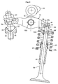
- Fig. 1 shows a valve operating mechanism for an internal combustion engine which opens and closes a valve by a rocker arm.
- the valve operating mechanism of a first embodiment includes a rocker arm 51 and a cam 53, etc. arranged above a roller 52 disposed adjacent to the rocker arm 51, and opens and closes a valve 54 through rocking of the rocker arm 51.
- This valve operating mechanism is of the end pivot type.
- a shaft portion 52a of the roller 52 At the center of the rocker arm 51, there is supported a shaft portion 52a of the roller 52.
- An adjust screw 55 is disposed adjacent to one end portion (on the side opposite to the valve) of the rocker arm 51.
- An adjust screw 55 is received by a support member (pivot receiving member) 56. That is, the adjust screw 55 has a semi-spherical convex portion 57, which is fit-engaged with a concave surface 58 of the pivot receiving member 56.
- a shaft portion 59 of the adjust screw 55 is threadedly engaged with one end portion (on the side opposite to the valve) of the rocker arm 51, and a nut 50 is threadedly engaged with a protrusion protruding from the upper end of one end portion of the rocker arm 51 and set in position.
- a slit 60 At the other end portion (on the valve side) of the rocker arm 51, there is provided a slit 60, which is connected by a connection member 61.
- the valve 54 is equipped with a valve stem portion 62, and a resilient member 63 fitted onto the valve stem portion 62.
- a spacer 65 is fitted onto a small diameter portion 64 of the valve stem portion 62, and a support member 66 is fitted onto the spacer 65.
- An upper end 63a of the resilient member 63 is supported by the support member 66.
- a lower end 63b of the resilient member 63 is supported by a fixing portion 67.
- the forward end portion (upper end portion) of the valve stem portion 62 abuts the connection member 61. That is, an upper end surface 71 of the valve stem portion 62 and a lower surface 73 of the connection member 61 are in contact with each other.
- the lower surface 73 of the connection member 61 is formed as a convex surface.
- the cam 53 rotates to thereby push down the rocker arm 51, and, through this pushing down, the valve stem portion 62 abutting the connection member 61 is pushed down, placing the valve 54 in the open state.
- the cam 53 further rotates to thereby cancel the force with which the rocker arm 51 is pushed down by the cam 53, the valve stem portion 62 ascends due to the resilient force of the resilient member 63, placing the valve 54 in the closed state.
- the convex portion 57 of the adjust screw 55 and the concave surface 58 of the pivot receiving member 56 are in sliding contact with each other.
- the upper end surface 71 of the valve stem portion 62 and the lower surface 73 of the connection member 61 are held in contact with each other.
- the upper end surface 71 of the valve stem portion 62 constitutes an arm contact surface held in contact with the rocker arm 51 side
- the lower surface 73 of the connection member 61 as the valve receiving portion of the rocker arm 51 constitutes a receiving surface brought into contact with the valve 54 side.
- a multiplicity of minute recesses are provided at random at least in one of the concave surface (contact surface) 58 of the pivot receiving member 56 and the convex portion (contact surface) 57 of the adjust screw 55.
- the surface roughness parameter Ryni of the surface provided with the recesses is set within the range of 0.4 ⁇ m ⁇ Ryni ⁇ 1.0 ⁇ m, with the Sk value being set to -1.6 or less.
- a multiplicity of minute recesses are provided at random in the arm contact surface of the valve 54 and in the receiving surface of the rocker arm 51.
- the surface roughness parameter Ryni of the surface provided with the recesses is set within the range of 0.4 ⁇ m ⁇ Ryni ⁇ 1.0 ⁇ m, with the Sk value being set to -1.6 or less.
- the average area of the recesses ranges from 30 to 100 ⁇ m 2
- Rymax ranges from 0.4 to 1.0 ⁇ m.
- the area ratio of the recesses of the surface - provided with the recesses ranges from 5 to 20%, and the surface roughness parameter Rymax of the surface provided with the recesses ranges from 0.4 to 1.0 ⁇ m.
- the surface roughness parameter Ryni of the surface provided with the recesses (contact portion) is set within the range of 0.4 ⁇ m ⁇ Ryni ⁇ 1.0 ⁇ m, whereby it is possible to prevent depletion of oil film even under a condition of thin lubrication, thereby enabling to attain a long service life even when the oil film thickness is extremely small. Further, by setting the Sk value of the contact portion to -1.6 or less in both the width direction and the circumferential direction, the minute recesses constitute oil sumps, and, even when compressed, little oil leakage is involved in the slipping direction and the right-angle direction, thereby attaining superior oil film formation property and minimizing surface damage.
- the adjust screw, the pivot receiving member, the rocker arm, and the valve of the present invention help to attain a long service life even under a condition of low viscosity and thin lubrication, with the oil film being extremely thin.
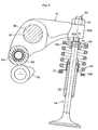
- valve operating mechanism is of the end pivot type.
- a valve cap 68 is attached to the forward end portion (upper end portion) of the valve stem portion 62, and the valve cap 68 is in contact with the connection member 61. That is, the valve cap 68 includes a short cylindrical body with an upper wall 68a, and is fitted onto the forward end portion (upper end portion) of the valve stem portion 62.
- an inner surface 70 of the upper wall 68a of the valve cap 68 comes into contact with the upper end surface 71 of the valve stem portion 62.
- an outer surface 72 of the upper wall 68a comes into contact with the lower surface 73 of the connection member 61.
- this embodiment is of the same construction as the valve operating mechanism as that shown in Fig. 1 , so the same components are indicated by the same reference numeral as those of Fig. 1 , and a redundant description thereof is omitted.
- the cam 53 rotates to thereby push down the rocker arm 51, and, through this pushing-down, the valve stem portion 62 is pushed down via the valve cap 68 in contact with the connection member 61, placing the valve 54 in the open state.
- the cam 53 further rotates to thereby cancel the force with which the rocker arm 51 is pushed down by the cam 53, the valve stem portion 62 ascends due to the resilient force of the resilient member 63, placing the valve 54 in the closed state.
- the inner surface 70 of the upper wall 68a of the valve cap 68 and the upper end surface 71 of the valve stem portion 62 are brought into contact with each other, and the outer surface 72 of the upper wall 68a and the lower surface 73 of the connection member 61 are brought into contact with each other.
- the inner surface 70 of the upper wall 68a constitutes the contact portion coming into contact with the valve side
- the outer surface 72 of the upper wall 68a constitutes the contact portion coming into contact with the rocker arm 51 side.
- a multiplicity of minute recesses are provided in at least one of the contact portion in contact with the valve 54 and the contact portion in contact with the rocker arm 51.
- the surface roughness parameter Ryni of the surface provided with the recesses is set within the range of 0.4 ⁇ m ⁇ Ryni ⁇ 1.0 ⁇ m, with the Sk value being set to -1.6 or less.
- the average area of the recesses ranges from 30 to 100 ⁇ m 2
- Rymax ranges from 0.4 to 1.0 ⁇ m.
- the area ratio of the recesses of the surface provided with the recesses ranges from 5 to 20%, and the surface roughness parameter Rymax of the surface provided with the recesses ranges from 0.4 to 1.0 ⁇ m.
- the valve cap of the valve operating device of the second embodiment can attain a long service life even under a condition of low viscosity and thin lubrication, with the oil film being extremely thin.
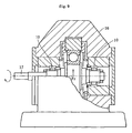
- Fig. 3 shows a third embodiment.
- This valve operating mechanism is of the center pivot type.
- This valve operating mechanism includes a rocker arm 81, and a cam 83, etc. arranged under a roller 82 disposed adjacent to the rocker arm 81, with the valve 54 being opened and closed through rocking of the rocker arm 51. Since the valve 54 is the same as the valve shown in Fig. 1 , it is indicated by the same reference numeral, and a redundant description thereof is omitted.
- the rocker arm 81 has a reverse-V-shaped configuration in front view.
- a rocker shaft 86 is passed through the central portion of the rocker arm 81, and the roller 82 is disposed adjacent to one end portion thereof (end portion on the side opposite to the valve) 81a, with an adjust screw 85 being disposed adjacent to the other end portion thereof (the end portion on the valve side) 81b.
- the adjust screw 85 is threadedly engaged with a screw hole provided at the other end portion 81b of the rocker arm 81, and a nut 87 is threadedly engaged with and set in position on a protrusion protruding from the upper end of the other end portion 81b of the rocker arm 81.
- the cam 83 rotates to thereby push up the one end portion 81a of the rocker arm 81, and, through this pushing up, the valve stem portion 62 abutting a lower surface 85a of the adjust screw 85 is pushed down, placing the valve 54 in the open state.
- the cam 83 further rotates to thereby cancel the force with which the rocker arm 81 is pushed up by the cam 83, the valve stem portion 62 ascends due to the resilient force of the resilient member 63, placing the valve 54 in the closed state.
- the rocker arm 81 swings around the rocker shaft axis, and the inner peripheral surface of a shaft insertion hole 90 of the rocker arm 81 and the outer peripheral surface of the rocker shaft corresponding to this inner peripheral surface are held in sliding contact with each other.
- a multiplicity of minute recesses are provided at random in the contact portion (contact surface) of one of the inner peripheral surface of the shaft insertion hole 90 of the rocker arm 81 and the outer peripheral surface of the rocker shaft 86 corresponding to this inner peripheral surface.
- the surface roughness parameter Ryni of the surface provided with the recesses is set within the range of 0.4 ⁇ m ⁇ Ryni ⁇ 1.0 ⁇ m, with the Sk value being set to -1.6 or less.
- a multiplicity of minute recesses are provided at random in the lower end surface (contact surface) 85a of the adjust screw 85, and the surface roughness parameter Ryni of the surface provided with the recesses is set within the range of 0.4 ⁇ m ⁇ Ryni ⁇ 1.0 ⁇ m, with the Sk value being set to -1.6 or less.
- the average area of the recesses ranges from 30 to 100 ⁇ m 2
- Rymax ranges from 0.4 to 1.0 ⁇ m.
- the area ratio of the recesses of the surface provided with the recesses ranges from 5 to 20%, and the surface roughness parameter Rymax of the surface provided with the recesses ranges from 0.4 to 1.0 ⁇ m.
- the rocker arm 81 and rocker shaft 86 of the third embodiment can attain a long service life even under a condition of low viscosity and thin lubrication, with the oil film being extremely thin.
- the lower end surface (contact surface) 85a of the adjust screw 85 of the third embodiment can attain a long service life even under a condition of low viscosity and thin lubrication, with the oil film being extremely thin.
- the surface of the object ismagnified, and quantification is possible from an image obtained by an image analysis system commercially available. Further, by using the surface property inspectionmethod and the surface property inspection device as disclosed in JP 2001-183124 A , it is possible to perform measurement accurately in a stable manner. According to this method, light is applied to an inspection surface with curvature, and the inspection surface is photographed by a camera. The luminance of the image of the inspection surface photographed by the camera is measured, and the surface properties of the inspection surface is inspected through a light/dark pattern formed through contrast of light and dark portions whose luminance has been measured.
- the light is applied in alignment with the optical axis direction of the camera, and positioning is effected on the inspection surface such that the position where the luminance distribution of the measured image indicates a peak value is matched with the optical axis of the camera, whereby the shading (luminance distribution) attributable to the curvature of the inspection surface is suppressed. Further, the light is applied in alignment with the optical axis direction of the camera, and the position on the inspection surface corresponding to the position where the luminance distribution of the measured image indicates a peak value is regarded as the origin.
- this orthogonal two-dimensional coordinate system one axis of which is the curvature symmetry axis, the one-dimensional luminance distributions along the orthogonal coordinate axes are approximated by approximation functions.
- the luminance of the measured image corresponding to each coordinate position is corrected so as to remove the luminance distribution of the image by using the peak value of the luminance distribution as a reference value, inspecting the surface properties of the inspection surface based on the light/dark pattern of the corrected luminance.
- the measurement condition is, for example, as follows. As in the case of the above-mentioned parameters, in measuring the area ratio and the average area of the recesses, a measurement value obtained at a single site is reliable as a typical value. However, it is advisable to perform measurement on, for example, two sites.
- FIG. 4 shows an example of a test rolling bearing.
- a rolling bearing 10 is a needle roller bearing into which a needle roller 12 is incorporated into an outer ring 13 as a rolling element, with a mating shaft 14 being supported by the needle roller 12.
- a plurality of kinds of needle roller bearings differing in finish surface treatment were prepared, and service life test was conducted thereon. The test results are as follows.
- the needle roller bearing used in the service life test was a bearing with a retainer 15 which has an outer diameter Dr of 33 mm and an inner diameter dr of 25 mm and which uses fifteen needle rollers 12 each having a diameter D1 of 4 mm and a length L of 25.8 mm.
- a bearing A (comparative example) which underwent super finish after grinding
- a bearing B (comparative example) with a multiplicity of minute recesses formed at random
- Figs. 6 to 8 show the finish surface conditions of the needle rollers of the test bearings. More specifically, Fig. 6 shows the surface roughness of the bearing A, Fig. 7 shows the surface roughness of the bearing B, and Fig. 8 shows the surface roughness of the bearing C and the bearing D.
- Table 1 shows the characteristic value parameters of the finish surfaces of the test bearings.
- the testing apparatus used was a radial load testing machine 16 as schematically shown in Fig. 9 .
- a test bearing 10 is mounted on both sides of a rotary shaft 17, and testing is conducted by imparting rotation and load thereto.
- the finishing of the inner race (mating shaft) used for the test is a polishing finish Ra of 0.10 to 0.16 ⁇ m. This also applies to the outer race (outer ring).
- the test conditions are as follows:
- the vertical axis indicates the service life (h).
- the bearing A exhibited a service life of 78 h
- the bearing B exhibited a service life of 82 h
- the bearings C and D exhibited service lives of 105 h and 121 h, respectively.
- the bearings C and D in which the needle roller surfaces have undergone surface treatment to satisfy the surface properties of the present invention, can provide a long service life even under a very hostile condition of low viscosity and thin lubrication, with the oil film parameter ⁇ being 0.13.
- the rocker arm, the rocker shaft, the valve cap, the adjust screw, the valve receiving portion, and the valve of the present invention in which the contact portions are set within the above value ranges, can provide a long service life.
- a gear pitching test was conducted by using a spur gear fatigue testing machine as shown in Fig. 11 to evaluate pitching strength.
- a drive side gear 31 (with 29 teeth) and a driven side gear 32 (with 30 teeth) are respectively mounted to one end of each of rotation shafts 33 and 34, and the drive side shaft 33 is driven by amotor (not shown) . Further, torque is imparted by a load lever 35 and a weight 36 mounted to the drive side shaft 33.
- Tables 3, 4, and 5 show the data obtained from the gear pitching test.
- Table 3 shows the results (comparative example) obtained in the case (a) in which surface treatment was conducted on neither the drive side nor the driven side gear
- Table 4 shows the results (example) obtained in the case (b) in which surface treatment to satisfy the surface properties of the present invention was effected on the tooth surface of the drive side gear
- Table 5 shows the results (example) obtained in the case (c) in which surface treatment to satisfy the surface properties of the present invention was effected on the tooth surfaces of both the drive side gear and the driven side gear.
- Those results confirms that, as compared with the case (a), the pitching service life is increased by two times or more in the case of (b), and by three times or more in the case of (c).
Claims (3)
- Bestandteil einer Ventilbetätigungseinrichtung, der ausgewählt wird aus einer Gruppe bestehend aus einem Kipphebel (51, 81) zum Öffnen und Schließen eines Ventils (54), einer Kipphebelachse (86), die den Kipphebel (51, 81) stützt, einer Ventilkappe (68), die an einem vorderen Ende des Ventils (54) angeordnet ist und am Kipphebel (51, 81) anstößt, einer Einstellschraube (55, 85), die an dem Kipphebel (51, 81) befestigt ist, einem Schwenkzapfenaufnahmeelement (56), das die Einstellschraube (55, 85) aufnimmt, und dem Ventil (54), wobei der Bestandteil dadurch gekennzeichnet ist, dass er Folgendes aufweist:eine Vielzahl winziger Ausnehmungen, die zumindest in einem Kontaktbereich,der mit einem anderen Element in Kontakt kommt, willkürlich angeordnet sind;undeine Oberfläche mit den Ausnehmungen, die einen Rautiefenparameter Ryni hat,der in einem Bereich von 0,4µm ≤ Ryni ≤ 1,0µm liegt, und einen Sk-Wert von -1,6 oder weniger.
- Bestandteil einer Ventilbetätigungseinrichtung nach Anspruch 1, bei dem eine durchschnittliche Fläche der Ausnehmungen der Oberfläche mit den Ausnehmungen in einem Bereich von 30 bis 100µm2 liegt und die Oberfläche mit den Ausnehmungen einen Rautiefenparameter Rymax hat, der im Bereich von 0,4 bis 1,0µm liegt.
- Bestandteil einer Ventilbetätigungseinrichtung nach Anspruch 1 oder 2, bei dem ein Verhältnis der Ausnehmungsfläche der Oberfläche mit den Ausnehmungen zwischen 5 und 20% liegt und die Oberfläche mit den Ausnehmungen einen Rautiefenparameter Rymax hat, der in einem Bereich von 0,4 bis 1,0µm liegt.
Applications Claiming Priority (5)
| Application Number | Priority Date | Filing Date | Title |
|---|---|---|---|
| JP2005376170A JP2007177677A (ja) | 2005-12-27 | 2005-12-27 | ロッカーアームおよびロッカーシャフト |
| JP2005378610A JP2007177733A (ja) | 2005-12-28 | 2005-12-28 | アーム式動弁装置のロッカーアーム及びバルブ |
| JP2005377632A JP2007177708A (ja) | 2005-12-28 | 2005-12-28 | バルブキャップ |
| JP2005377645A JP2007177710A (ja) | 2005-12-28 | 2005-12-28 | アジャストスクリューおよびピボット受け部材 |
| PCT/JP2006/325834 WO2007077804A1 (ja) | 2005-12-27 | 2006-12-26 | アーム式動弁装置のロッカーアーム、ロッカーシャフト、バルブキャップ、アジャストスクリュー、ピボット受け部材、及びバルブ |
Publications (3)
| Publication Number | Publication Date |
|---|---|
| EP1967703A1 EP1967703A1 (de) | 2008-09-10 |
| EP1967703A4 EP1967703A4 (de) | 2009-11-11 |
| EP1967703B1 true EP1967703B1 (de) | 2011-03-23 |
Family
ID=38228157
Family Applications (1)
| Application Number | Title | Priority Date | Filing Date |
|---|---|---|---|
| EP06843218A Not-in-force EP1967703B1 (de) | 2005-12-27 | 2006-12-26 | Verriegelungsarm, verriegelungsbolzen, ventilkappe, einstellschraube, gelenkaufnahmeglied und ventil einer armartigen ventilbetriebsvorrichtung |
Country Status (4)
| Country | Link |
|---|---|
| US (1) | US8118004B2 (de) |
| EP (1) | EP1967703B1 (de) |
| DE (1) | DE602006020925D1 (de) |
| WO (1) | WO2007077804A1 (de) |
Cited By (1)
| Publication number | Priority date | Publication date | Assignee | Title |
|---|---|---|---|---|
| EP2682230A2 (de) | 2012-07-06 | 2014-01-08 | MAHLE International GmbH | Verfahren zur Herstellung/Bearbeitung eines Nockens |
Families Citing this family (2)
| Publication number | Priority date | Publication date | Assignee | Title |
|---|---|---|---|---|
| US10557382B2 (en) * | 2015-02-11 | 2020-02-11 | R. Bradford Fawley | Valve clearance setting and adjustment systems and related methods |
| CN110925043A (zh) * | 2019-11-28 | 2020-03-27 | 哈尔滨东安汽车动力股份有限公司 | 一种斜置发动机使用滚子摇臂、机械挺柱结构 |
Family Cites Families (27)
| Publication number | Priority date | Publication date | Assignee | Title |
|---|---|---|---|---|
| AT404288B (de) * | 1986-10-30 | 1998-10-27 | Avl Verbrennungskraft Messtech | Motorbremse bei einer brennkraftmaschine für kraftfahrzeuge |
| JP2758518B2 (ja) | 1988-05-30 | 1998-05-28 | エヌティエヌ株式会社 | 転動ローラ |
| GB2219359B (en) | 1988-05-30 | 1992-11-04 | Ntn Toyo Bearing Co Ltd | Roller elements for machine parts such as roller bearings. |
| JP2594339B2 (ja) * | 1988-11-09 | 1997-03-26 | エヌティエヌ株式会社 | エンジンのローラ付カムフォロア |
| JPH07113385B2 (ja) | 1989-01-20 | 1995-12-06 | エヌティエヌ株式会社 | ワンウェイクラッチ |
| JPH03117724A (ja) | 1989-09-28 | 1991-05-20 | Ntn Corp | ころ軸受 |
| JP2724219B2 (ja) | 1989-09-28 | 1998-03-09 | エヌティエヌ株式会社 | 転がり軸受 |
| JP2548811B2 (ja) * | 1989-11-30 | 1996-10-30 | エヌティエヌ株式会社 | 機械部品 |
| JP2634496B2 (ja) | 1991-02-28 | 1997-07-23 | エヌティエヌ株式会社 | エンジンのローラ付カムフォロア |
| JPH04321816A (ja) | 1991-04-18 | 1992-11-11 | Ntn Corp | 歯車軸支持装置 |
| US5456136A (en) * | 1991-04-24 | 1995-10-10 | Ntn Corporation | Cam follower with roller for use with engine |
| DE4113944A1 (de) | 1991-05-01 | 1992-11-12 | Ntn Toyo Bearing Co Ltd | Homokinetisches universalgelenk |
| JPH05239550A (ja) * | 1992-02-27 | 1993-09-17 | Ntn Corp | ころがり部品 |
| DE4418245C2 (de) | 1993-08-14 | 2003-06-18 | Ina Schaeffler Kg | Verfahren zur thermochemisch-thermischen Behandlung einer Gleitfläche eines Nockens und/oder einer Gleitfläche eines Nockengegenläufers |
| JPH07150921A (ja) | 1993-11-30 | 1995-06-13 | Mitsubishi Motors Corp | ロッカアームの潤滑構造 |
| JPH0835408A (ja) | 1994-07-27 | 1996-02-06 | Toyota Motor Corp | アジャストスクリュー |
| JP3524978B2 (ja) | 1995-03-02 | 2004-05-10 | 光洋精工株式会社 | カムフォロワ用ローラ |
| JP3869138B2 (ja) | 1999-01-13 | 2007-01-17 | 株式会社ジェイテクト | 転がり摺動部品 |
| JP2001152817A (ja) | 1999-12-01 | 2001-06-05 | Teikoku Piston Ring Co Ltd | ロッカアーム及び内燃機関の動弁機構 |
| JP2001263031A (ja) | 2000-03-22 | 2001-09-26 | Kubota Corp | エンジンの動弁潤滑装置 |
| JP4031188B2 (ja) | 2000-09-21 | 2008-01-09 | 株式会社ジェイテクト | ロッカアーム |
| JP2004125049A (ja) | 2002-10-02 | 2004-04-22 | Nissan Motor Co Ltd | 摺動部材及びその製造方法 |
| JP2004340128A (ja) * | 2003-03-31 | 2004-12-02 | Nippon Piston Ring Co Ltd | 内燃機関の動弁装置 |
| JP2005264736A (ja) | 2004-03-16 | 2005-09-29 | Otics Corp | バルブ開閉機構 |
| DE602005027842D1 (de) | 2004-06-25 | 2011-06-16 | Ntn Toyo Bearing Co Ltd | Walzlager |
| WO2006003792A1 (ja) | 2004-07-05 | 2006-01-12 | Ntn Corporation | 自動車用ころ軸受 |
| JP2006022935A (ja) | 2004-07-05 | 2006-01-26 | Ntn Corp | 円すいころ軸受 |
-
2006
- 2006-12-26 DE DE602006020925T patent/DE602006020925D1/de active Active
- 2006-12-26 WO PCT/JP2006/325834 patent/WO2007077804A1/ja active Application Filing
- 2006-12-26 US US12/085,654 patent/US8118004B2/en not_active Expired - Fee Related
- 2006-12-26 EP EP06843218A patent/EP1967703B1/de not_active Not-in-force
Cited By (2)
| Publication number | Priority date | Publication date | Assignee | Title |
|---|---|---|---|---|
| EP2682230A2 (de) | 2012-07-06 | 2014-01-08 | MAHLE International GmbH | Verfahren zur Herstellung/Bearbeitung eines Nockens |
| DE102012211864A1 (de) | 2012-07-06 | 2014-05-22 | Mahle International Gmbh | Verfahren zur Herstellung/Bearbeitung eines Nockens |
Also Published As
| Publication number | Publication date |
|---|---|
| EP1967703A1 (de) | 2008-09-10 |
| EP1967703A4 (de) | 2009-11-11 |
| WO2007077804A1 (ja) | 2007-07-12 |
| DE602006020925D1 (de) | 2011-05-05 |
| US20090266324A1 (en) | 2009-10-29 |
| US8118004B2 (en) | 2012-02-21 |
Similar Documents
| Publication | Publication Date | Title |
|---|---|---|
| US6328477B1 (en) | Tapered roller bearings and gear shaft support devices | |
| EP1632685B1 (de) | Zylindrisches rollenlager | |
| EP1770290A1 (de) | Walzlager | |
| US6598571B1 (en) | Cam follower with roller | |
| US7484890B2 (en) | Rolling slide member | |
| EP1967703B1 (de) | Verriegelungsarm, verriegelungsbolzen, ventilkappe, einstellschraube, gelenkaufnahmeglied und ventil einer armartigen ventilbetriebsvorrichtung | |
| US8136420B2 (en) | Gear and gear drive unit | |
| US8024989B2 (en) | Gear and gear drive unit | |
| JP2007177677A (ja) | ロッカーアームおよびロッカーシャフト | |
| EP1770291A1 (de) | Walzlager | |
| JP2007177710A (ja) | アジャストスクリューおよびピボット受け部材 | |
| JP2006316821A (ja) | プラネタリギヤ機構用転がり軸受 | |
| JP2007187191A (ja) | 減速機 | |
| WO2006001149A1 (ja) | 転がり軸受 | |
| JP2007177733A (ja) | アーム式動弁装置のロッカーアーム及びバルブ | |
| JP2007187190A (ja) | シンクロナイザリング | |
| JP4537320B2 (ja) | 燃料噴射ポンプ | |
| JP2007187023A (ja) | スクロールコンプレッサ | |
| JP2007170627A (ja) | スプラグ及びワンウェイクラッチ | |
| JPWO2008050379A1 (ja) | 歯車および歯車駆動装置 | |
| EP1801365A1 (de) | Lager für schwingarm | |
| JP2007177708A (ja) | バルブキャップ | |
| JP2007177729A (ja) | タペット用シム | |
| JP2007127260A (ja) | 歯車および歯車駆動装置 | |
| JP2007127261A (ja) | 歯車および歯車駆動装置 |
Legal Events
| Date | Code | Title | Description |
|---|---|---|---|
| PUAI | Public reference made under article 153(3) epc to a published international application that has entered the european phase |
Free format text: ORIGINAL CODE: 0009012 |
|
| 17P | Request for examination filed |
Effective date: 20080530 |
|
| AK | Designated contracting states |
Kind code of ref document: A1 Designated state(s): AT BE BG CH CY CZ DE DK EE ES FI FR GB GR HU IE IS IT LI LT LU LV MC NL PL PT RO SE SI SK TR |
|
| RTI1 | Title (correction) |
Free format text: ROCKER ARM, ROCKER SHAFT, VALVE CAP, ADJUST SCREW, PIVOT RECEIVING MEMBER, AND VALVE OF ARM TYPE VALVE OPERATING DEVICE |
|
| A4 | Supplementary search report drawn up and despatched |
Effective date: 20090910 |
|
| 17Q | First examination report despatched |
Effective date: 20091223 |
|
| GRAP | Despatch of communication of intention to grant a patent |
Free format text: ORIGINAL CODE: EPIDOSNIGR1 |
|
| DAX | Request for extension of the european patent (deleted) | ||
| GRAS | Grant fee paid |
Free format text: ORIGINAL CODE: EPIDOSNIGR3 |
|
| GRAA | (expected) grant |
Free format text: ORIGINAL CODE: 0009210 |
|
| AK | Designated contracting states |
Kind code of ref document: B1 Designated state(s): AT BE BG CH CY CZ DE DK EE ES FI FR GB GR HU IE IS IT LI LT LU LV MC NL PL PT RO SE SI SK TR |
|
| REG | Reference to a national code |
Ref country code: GB Ref legal event code: FG4D |
|
| REG | Reference to a national code |
Ref country code: CH Ref legal event code: EP |
|
| REG | Reference to a national code |
Ref country code: IE Ref legal event code: FG4D |
|
| REF | Corresponds to: |
Ref document number: 602006020925 Country of ref document: DE Date of ref document: 20110505 Kind code of ref document: P |
|
| REG | Reference to a national code |
Ref country code: DE Ref legal event code: R096 Ref document number: 602006020925 Country of ref document: DE Effective date: 20110505 |
|
| REG | Reference to a national code |
Ref country code: NL Ref legal event code: VDEP Effective date: 20110323 |
|
| PG25 | Lapsed in a contracting state [announced via postgrant information from national office to epo] |
Ref country code: GR Free format text: LAPSE BECAUSE OF FAILURE TO SUBMIT A TRANSLATION OF THE DESCRIPTION OR TO PAY THE FEE WITHIN THE PRESCRIBED TIME-LIMIT Effective date: 20110624 Ref country code: LT Free format text: LAPSE BECAUSE OF FAILURE TO SUBMIT A TRANSLATION OF THE DESCRIPTION OR TO PAY THE FEE WITHIN THE PRESCRIBED TIME-LIMIT Effective date: 20110323 Ref country code: SE Free format text: LAPSE BECAUSE OF FAILURE TO SUBMIT A TRANSLATION OF THE DESCRIPTION OR TO PAY THE FEE WITHIN THE PRESCRIBED TIME-LIMIT Effective date: 20110323 Ref country code: LV Free format text: LAPSE BECAUSE OF FAILURE TO SUBMIT A TRANSLATION OF THE DESCRIPTION OR TO PAY THE FEE WITHIN THE PRESCRIBED TIME-LIMIT Effective date: 20110323 |
|
| LTIE | Lt: invalidation of european patent or patent extension |
Effective date: 20110323 |
|
| PG25 | Lapsed in a contracting state [announced via postgrant information from national office to epo] |
Ref country code: BG Free format text: LAPSE BECAUSE OF FAILURE TO SUBMIT A TRANSLATION OF THE DESCRIPTION OR TO PAY THE FEE WITHIN THE PRESCRIBED TIME-LIMIT Effective date: 20110623 Ref country code: SI Free format text: LAPSE BECAUSE OF FAILURE TO SUBMIT A TRANSLATION OF THE DESCRIPTION OR TO PAY THE FEE WITHIN THE PRESCRIBED TIME-LIMIT Effective date: 20110323 Ref country code: CY Free format text: LAPSE BECAUSE OF FAILURE TO SUBMIT A TRANSLATION OF THE DESCRIPTION OR TO PAY THE FEE WITHIN THE PRESCRIBED TIME-LIMIT Effective date: 20110323 Ref country code: FI Free format text: LAPSE BECAUSE OF FAILURE TO SUBMIT A TRANSLATION OF THE DESCRIPTION OR TO PAY THE FEE WITHIN THE PRESCRIBED TIME-LIMIT Effective date: 20110323 Ref country code: AT Free format text: LAPSE BECAUSE OF FAILURE TO SUBMIT A TRANSLATION OF THE DESCRIPTION OR TO PAY THE FEE WITHIN THE PRESCRIBED TIME-LIMIT Effective date: 20110323 |
|
| PG25 | Lapsed in a contracting state [announced via postgrant information from national office to epo] |
Ref country code: BE Free format text: LAPSE BECAUSE OF FAILURE TO SUBMIT A TRANSLATION OF THE DESCRIPTION OR TO PAY THE FEE WITHIN THE PRESCRIBED TIME-LIMIT Effective date: 20110323 |
|
| PG25 | Lapsed in a contracting state [announced via postgrant information from national office to epo] |
Ref country code: EE Free format text: LAPSE BECAUSE OF FAILURE TO SUBMIT A TRANSLATION OF THE DESCRIPTION OR TO PAY THE FEE WITHIN THE PRESCRIBED TIME-LIMIT Effective date: 20110323 Ref country code: PT Free format text: LAPSE BECAUSE OF FAILURE TO SUBMIT A TRANSLATION OF THE DESCRIPTION OR TO PAY THE FEE WITHIN THE PRESCRIBED TIME-LIMIT Effective date: 20110725 |
|
| PG25 | Lapsed in a contracting state [announced via postgrant information from national office to epo] |
Ref country code: IS Free format text: LAPSE BECAUSE OF FAILURE TO SUBMIT A TRANSLATION OF THE DESCRIPTION OR TO PAY THE FEE WITHIN THE PRESCRIBED TIME-LIMIT Effective date: 20110723 Ref country code: RO Free format text: LAPSE BECAUSE OF FAILURE TO SUBMIT A TRANSLATION OF THE DESCRIPTION OR TO PAY THE FEE WITHIN THE PRESCRIBED TIME-LIMIT Effective date: 20110323 Ref country code: SK Free format text: LAPSE BECAUSE OF FAILURE TO SUBMIT A TRANSLATION OF THE DESCRIPTION OR TO PAY THE FEE WITHIN THE PRESCRIBED TIME-LIMIT Effective date: 20110323 Ref country code: ES Free format text: LAPSE BECAUSE OF FAILURE TO SUBMIT A TRANSLATION OF THE DESCRIPTION OR TO PAY THE FEE WITHIN THE PRESCRIBED TIME-LIMIT Effective date: 20110704 Ref country code: CZ Free format text: LAPSE BECAUSE OF FAILURE TO SUBMIT A TRANSLATION OF THE DESCRIPTION OR TO PAY THE FEE WITHIN THE PRESCRIBED TIME-LIMIT Effective date: 20110323 |
|
| PG25 | Lapsed in a contracting state [announced via postgrant information from national office to epo] |
Ref country code: NL Free format text: LAPSE BECAUSE OF FAILURE TO SUBMIT A TRANSLATION OF THE DESCRIPTION OR TO PAY THE FEE WITHIN THE PRESCRIBED TIME-LIMIT Effective date: 20110323 |
|
| PLBE | No opposition filed within time limit |
Free format text: ORIGINAL CODE: 0009261 |
|
| STAA | Information on the status of an ep patent application or granted ep patent |
Free format text: STATUS: NO OPPOSITION FILED WITHIN TIME LIMIT |
|
| 26N | No opposition filed |
Effective date: 20111227 |
|
| PG25 | Lapsed in a contracting state [announced via postgrant information from national office to epo] |
Ref country code: PL Free format text: LAPSE BECAUSE OF FAILURE TO SUBMIT A TRANSLATION OF THE DESCRIPTION OR TO PAY THE FEE WITHIN THE PRESCRIBED TIME-LIMIT Effective date: 20110323 Ref country code: DK Free format text: LAPSE BECAUSE OF FAILURE TO SUBMIT A TRANSLATION OF THE DESCRIPTION OR TO PAY THE FEE WITHIN THE PRESCRIBED TIME-LIMIT Effective date: 20110323 |
|
| REG | Reference to a national code |
Ref country code: DE Ref legal event code: R097 Ref document number: 602006020925 Country of ref document: DE Effective date: 20111227 |
|
| PG25 | Lapsed in a contracting state [announced via postgrant information from national office to epo] |
Ref country code: IT Free format text: LAPSE BECAUSE OF FAILURE TO SUBMIT A TRANSLATION OF THE DESCRIPTION OR TO PAY THE FEE WITHIN THE PRESCRIBED TIME-LIMIT Effective date: 20110323 |
|
| PG25 | Lapsed in a contracting state [announced via postgrant information from national office to epo] |
Ref country code: MC Free format text: LAPSE BECAUSE OF NON-PAYMENT OF DUE FEES Effective date: 20111231 |
|
| REG | Reference to a national code |
Ref country code: CH Ref legal event code: PL |
|
| GBPC | Gb: european patent ceased through non-payment of renewal fee |
Effective date: 20111226 |
|
| REG | Reference to a national code |
Ref country code: IE Ref legal event code: MM4A |
|
| PG25 | Lapsed in a contracting state [announced via postgrant information from national office to epo] |
Ref country code: CH Free format text: LAPSE BECAUSE OF NON-PAYMENT OF DUE FEES Effective date: 20111231 Ref country code: IE Free format text: LAPSE BECAUSE OF NON-PAYMENT OF DUE FEES Effective date: 20111226 Ref country code: GB Free format text: LAPSE BECAUSE OF NON-PAYMENT OF DUE FEES Effective date: 20111226 Ref country code: LI Free format text: LAPSE BECAUSE OF NON-PAYMENT OF DUE FEES Effective date: 20111231 |
|
| PG25 | Lapsed in a contracting state [announced via postgrant information from national office to epo] |
Ref country code: LU Free format text: LAPSE BECAUSE OF NON-PAYMENT OF DUE FEES Effective date: 20111226 |
|
| PG25 | Lapsed in a contracting state [announced via postgrant information from national office to epo] |
Ref country code: TR Free format text: LAPSE BECAUSE OF FAILURE TO SUBMIT A TRANSLATION OF THE DESCRIPTION OR TO PAY THE FEE WITHIN THE PRESCRIBED TIME-LIMIT Effective date: 20110323 |
|
| PG25 | Lapsed in a contracting state [announced via postgrant information from national office to epo] |
Ref country code: HU Free format text: LAPSE BECAUSE OF FAILURE TO SUBMIT A TRANSLATION OF THE DESCRIPTION OR TO PAY THE FEE WITHIN THE PRESCRIBED TIME-LIMIT Effective date: 20110323 |
|
| REG | Reference to a national code |
Ref country code: FR Ref legal event code: PLFP Year of fee payment: 10 |
|
| REG | Reference to a national code |
Ref country code: FR Ref legal event code: PLFP Year of fee payment: 11 |
|
| PGFP | Annual fee paid to national office [announced via postgrant information from national office to epo] |
Ref country code: FR Payment date: 20161111 Year of fee payment: 11 Ref country code: DE Payment date: 20161220 Year of fee payment: 11 |
|
| REG | Reference to a national code |
Ref country code: DE Ref legal event code: R119 Ref document number: 602006020925 Country of ref document: DE |
|
| REG | Reference to a national code |
Ref country code: FR Ref legal event code: ST Effective date: 20180831 |
|
| PG25 | Lapsed in a contracting state [announced via postgrant information from national office to epo] |
Ref country code: DE Free format text: LAPSE BECAUSE OF NON-PAYMENT OF DUE FEES Effective date: 20180703 Ref country code: FR Free format text: LAPSE BECAUSE OF NON-PAYMENT OF DUE FEES Effective date: 20180102 |