EP1965265A2 - Bilderzeugungsvorrichtung - Google Patents
Bilderzeugungsvorrichtung Download PDFInfo
- Publication number
- EP1965265A2 EP1965265A2 EP08100039A EP08100039A EP1965265A2 EP 1965265 A2 EP1965265 A2 EP 1965265A2 EP 08100039 A EP08100039 A EP 08100039A EP 08100039 A EP08100039 A EP 08100039A EP 1965265 A2 EP1965265 A2 EP 1965265A2
- Authority
- EP
- European Patent Office
- Prior art keywords
- lever member
- guide rail
- pressing portion
- guide lever
- guide
- Prior art date
- Legal status (The legal status is an assumption and is not a legal conclusion. Google has not performed a legal analysis and makes no representation as to the accuracy of the status listed.)
- Granted
Links
Images




Classifications
-
- G—PHYSICS
- G03—PHOTOGRAPHY; CINEMATOGRAPHY; ANALOGOUS TECHNIQUES USING WAVES OTHER THAN OPTICAL WAVES; ELECTROGRAPHY; HOLOGRAPHY
- G03G—ELECTROGRAPHY; ELECTROPHOTOGRAPHY; MAGNETOGRAPHY
- G03G21/00—Arrangements not provided for by groups G03G13/00 - G03G19/00, e.g. cleaning, elimination of residual charge
- G03G21/16—Mechanical means for facilitating the maintenance of the apparatus, e.g. modular arrangements
- G03G21/1604—Arrangement or disposition of the entire apparatus
- G03G21/1623—Means to access the interior of the apparatus
- G03G21/1628—Clamshell type
-
- G—PHYSICS
- G03—PHOTOGRAPHY; CINEMATOGRAPHY; ANALOGOUS TECHNIQUES USING WAVES OTHER THAN OPTICAL WAVES; ELECTROGRAPHY; HOLOGRAPHY
- G03G—ELECTROGRAPHY; ELECTROPHOTOGRAPHY; MAGNETOGRAPHY
- G03G2221/00—Processes not provided for by group G03G2215/00, e.g. cleaning or residual charge elimination
- G03G2221/16—Mechanical means for facilitating the maintenance of the apparatus, e.g. modular arrangements and complete machine concepts
- G03G2221/1651—Mechanical means for facilitating the maintenance of the apparatus, e.g. modular arrangements and complete machine concepts for connecting the different parts
- G03G2221/1654—Locks and means for positioning or alignment
-
- G—PHYSICS
- G03—PHOTOGRAPHY; CINEMATOGRAPHY; ANALOGOUS TECHNIQUES USING WAVES OTHER THAN OPTICAL WAVES; ELECTROGRAPHY; HOLOGRAPHY
- G03G—ELECTROGRAPHY; ELECTROPHOTOGRAPHY; MAGNETOGRAPHY
- G03G2221/00—Processes not provided for by group G03G2215/00, e.g. cleaning or residual charge elimination
- G03G2221/16—Mechanical means for facilitating the maintenance of the apparatus, e.g. modular arrangements and complete machine concepts
- G03G2221/1678—Frame structures
- G03G2221/1687—Frame structures using opening shell type machines, e.g. pivoting assemblies
Definitions
- aspects of the present invention relate to an image forming apparatus, and more particularly, to an image forming apparatus with an improved opening and closing structure.
- an image forming apparatus (such as a printer, a photocopier, and a facsimile machine) has a cover that opens and closes an upper portion of a body in order to facilitate repair/maintenance of the components provided in the body and/or to remove paper jammed in a paper conveyance path.
- Such an image forming apparatus requires an opening and closing apparatus to maintain the cover in an open state and a closed state.
- a conventional opening and closing apparatus for maintaining a cover in an open state and a closed state is disclosed in Japanese Patent Publication Nos. H8-143054 and H10-98278 .
- the opening and closing apparatus disclosed in Japanese Patent Publication Nos. H8-143054 and H10-9872 only has a cover function and is inefficient if the cover is heavy.
- the cover is provided with an additional device (such as a scanner or an automatic document feeder (ADF)) that adds weight to the cover, there is a problem in maintaining the cover in the open state. As a result, the cover abruptly closes causing damage to the body.
- ADF automatic document feeder
- Japanese Patent Publication No. 2006-119474 discloses an image forming apparatus that, despite including a heavy cover unit, is capable of maintaining the cover unit in an open state.
- the image forming apparatus disclosed in Japanese Patent Publication No. 2006-119474 includes a locking member provided at either an image forming unit or an image reading unit, and a link member having one end supported by the other unit and the other end engaged with the locking member when the image reading unit is in an open state. The link member links both of the units in the open state.
- the image forming apparatus disclosed in Japanese Publication No. 2006-119474 must include an extension coil spring in order to elastically support the other end of the link member and maintain the link member in an open state. That is, in the absence of the extension coil spring, the up-standing state of the link member is unstable and thus a cover unit is likely to abruptly close during work (such as repair/maintenance or jammed paper removal). In this case, damage to the body and/or injuries to a user's fingers result.
- aspects which of the present invention provide an image forming apparatus having a simplified structure and which stably maintains a body in an open state during repair/maintenance work, thereby providing a user with added convenience.
- an image forming apparatus including: a first body to perform an image forming operation on a print medium; a second body to pivot between a closed position and an open position in relation to the first body; a guide lever member to control a pivoting of the second body, the guide lever member having a first end connected to one of the first body and the second body, and a second end, opposite the first end; and a guide rail member including: a guide rail along which the second end of the guide lever member is connected to slide between a first end of the guide rail corresponding to the open position of the second body and a second end of the guide rail corresponding to the closed position of the second body, a first pressing portion to constrain the second end of the guide lever member in the first end of the guide rail when the second body is in the open position, and a second pressing portion to prevent the second body from abruptly pivoting from the open position to the closed position.
- the first and the second bodies may have the same widths and lengths, the second body may be provided with a laser scanning unit, and the first body may be provided with image forming units that are arranged to form a C-shaped print medium path.
- the image forming units may include a feeding unit, a developing unit, a transfer unit, a fusing unit, and/or a paper discharge unit.
- a scanner unit may further be provided on the second body.
- the guide rail member may be provided on the first body.
- the guide lever member may be connected to the second body.
- the first pressing portion may include a first elastic bending portion provided on the first side of the guide rail and upwardly bending, and a first elastic space under the first elastic bending portion.
- a first elastic member may be provided in the first elastic space to elastically support the first elastic bending portion.
- the second pressing portion may include a second elastic bending portion provided on the second side of the guide rail and upwardly bending, and a second elastic space under the second elastic bending portion.
- a second elastic member may be provided in the second elastic space to elastically support the second elastic bending portion.
- the first pressing portion and the second pressing portion may have different heights, and the height of the second pressing portion may be greater than the height of the first pressing portion.
- a C-shaped recess may be formed on the first end of the guide lever member to be hooked over a shaft provided on the second body.
- a protrusion may be provided on the second end of the guide lever member to be prevented from being released from the guide rail.
- An open angle of the second body with respect to the first body may range from 40° to about 80°.
- an image forming apparatus comprising: a first body; a second body to pivot between a closed position and an open position in relation to the first body; a plurality of guide lever members to control a pivoting of the second body, each guide lever member having a first end connected to one of the first body and the second body, and a second end, opposite the first end; and a plurality of guide rail members, each corresponding to one guide lever member comprising: a guide rail along which the second end of the corresponding guide lever member is slidably connected.
- the guide rail member includes a guide rail having a first pressing portion to constrain the second end of the guide lever member in the open state of the second body, and a second pressing portion to prevent the second body from abruptly closing while the second body is being closed.
- Three or more pressing portions may be provided, according to the weight of the second body.
- an image forming apparatus including: a first body to perform an image forming operation on a print medium; a second body to pivot between a closed position and an open position in relation to the first body; a guide lever member to control a pivoting of the second body, the guide lever member having a first end connected to one of the first body and the second body, and a second end, opposite the first end; and a guide rail member including: a guide rail along which the second end of the guide lever member is connected to slide between a first end of the guide rail corresponding to the open position of the second body and a second end of the guide rail corresponding to the closed position of the second body, and a first pressing portion to constrain the second end of the guide lever member in the first end of the guide rail when the second body is in the open position.
- an image forming apparatus including: a first body to perform an image forming operation on a print medium; a second body to pivot between a closed position and an open position in relation to the first body; and an opening/closing unit to guide the second body to be open and closed in relation to the first body, wherein the opening/closing unit includes: a guide lever member to control a pivoting of the second body, the guide lever member having a first end connected to one of the first body and the second body, and a second end, opposite the first end; and a guide rail member to be formed in the other one of the first body and the second body, and to be movably connected to the second end of the guide lever member, the guide rail member comprising a pressing portion to constrain the second body, the pressing portion putting pressure in a direction different from the movement of the guide lever member.
- force generated by the weight of the second body may be almost opposite to the direction of the pressure of the pressing portion.
- the pressing portion may press a plurality of areas.
- the pressing portion may press an area around a first end and a second end of an area in which the guide lever member moves.
- a number of the pressing portion may be plural, and the plurality of pressing portions may have different pressure.
- an image forming apparatus includes a first body 10, a second body 20 to pivot open and closed in relation to the first body 10, and an opening and closing apparatus 30 to guide opening and closing operations of the second body 20 with respect to the first body 10.
- the first body 10 and the second body 20 are connected to each other by a hinge unit 40 so that the second body 20 is configured to pivot from the first body 10.
- the opening and closing apparatus 30 guides opening and closing operations of the second body 20 from a position different from that of the hinge unit 40.
- the first body 10 and the second body 20 may have equal or almost equal widths and/or lengths. Furthermore, a top surface of the second body 20 may be flat.
- the first body 10 includes a printing unit (i.e., components used to form an image, such as a print medium feeding unit 11, a developing unit 12, a transfer unit 13, a fusing unit 14, and a print medium discharge unit 15). These components may be arranged to form a C-shaped paper path.
- the second body 20 includes a laser scanning unit 21 and a scanner unit 22.
- the print medium supplied by the print medium feeding unit 11 may be any medium on which an image may be formed (such as paper or transparencies)
- the second body 20 is provided to pivot on the hinge unit 40 and open the first body 10 in order to, for example, facilitate repair/maintenance work for the components in the first body 10 and/or the second body 20 or removal of jammed paper.
- the opening and closing apparatus 30 guides the opening and closing operations of the second body 20.
- the opening and closing apparatus 30 prevents the second body 20 from excessively rotating, and maintains the second body 20 in an open state at a predetermined angle. Furthermore, the opening and closing apparatus 30 prevents the second body 20 from abruptly closing due to the weight of the second body 10.
- the second body 20 may, although not necessarily, open with respect to the first body 10 at an angle ranging from 40° to 80°.
- the opening and closing apparatus 30 includes a guide lever member 50 having one end connected to the second body 20 and a guide rail member 60 provided on the first body 10.
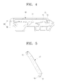
- the guide lever member 50 has a C-shaped recess 51 on a first end thereof.
- the recess 51 is hooked over a shaft 23 provided on the second body 20 in order to connect to the second body 20.
- the guide lever member 50 has a moving shaft 52 (to be described later) provided on a second end, opposite the first end, to connect to the guide rail member 60.
- the guide lever member 50 has an end portion on which a release preventing protrusion 53 is provided. It is understood that other methods and devices may be used to connect the guide lever member 50 to the second body 20 and the guide rail member 60.
- the guide rail member 60 is connected to a side surface of the first body 10 by a fastening element (such as a screw).
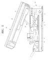
- the guide rail member 60 is provided with a guide rail 61 into which the moving shaft 52 of the guide lever member 50 is inserted. Accordingly, the moving shaft 52 slides along the guide rail 61.
- the guide rail 61 includes a first pressing portion 70 and a second pressing portion 80.
- the first pressing portion 70 constrains the second end portion of the guide lever member 50 in a set position. That is, the first pressing portion 70 restricts the moving shaft 52 from moving when the second body 20 is opened by a user, thereby maintaining the open state of the second body 20.
- the first pressing portion 70 includes a first elastic bending portion 71 and a first elastic space 72 provided under the first elastic bending portion 71.
- the moving shaft 52 of the guide lever member 50 slides from an initial position toward the first pressing portion 70 along the guide rail 61.
- the moving shaft 52 moves over the first pressing portion 70. If an external force applied by the user is removed while the second body is completely opened (i.e., in the open state), a force generated due to a weight of the second body 20 is exerted on the guide rail member 50. Since the moving shaft 52 of the guide lever member 50 is supported in the first pressing portion 70 and the elasticity of the first pressing portion 70 is set to be greater than the force generated by the weight of the second body 20, the second body 20 remains in the open state unless an additional external force is applied.
- the second pressing portion 80 prevents the second body 20 from abruptly closing due to the weight of the second body 20.
- the second body 20 includes a second elastic bending portion 81 and a second elastic space 82 provided under the second elastic bending portion 81. More specifically, when an external force is applied to the second body 20 when the second body 20 is in the open state (described above), the moving shaft 52 of the guide lever member 50 that is supported in the first pressing portion 70 overcomes the elasticity of the first pressing portion 70 and slides toward the second pressing portion 80 along the guide rail 61. Since the second pressing portion 80 is elastically supported in an opposite direction to the direction in which the moving shaft 52 moves, the moving shaft 52 moves gradually, overcoming the elasticity of the second pressing portion 80. Accordingly, the second body 20 closes gradually.
- the second pressing portion 80 elastically supports the moving shaft 52 at the initial location. Accordingly, the second body 20 is not raised or opened unless an additional external force is applied.
- the guide lever member 50 is regulated between at least two locations and the second body 20 is prevented from being closed from a weight of the second body 20.
- the conventional apparatus disclosed in Japanese Patent Publication No. 2006-119474 requires an extension coil spring to achieve the above-described effect.
- aspects of the present invention can achieve the effect without an additional member such as a spring.
- the direction of an external force applied to the guide lever member 50 is different from the sliding direction of the guide lever member 50, so when excessive force is not required to open or close the second pressing portion 20.
- the direction of an external force and the sliding direction are different, so excessive force is not necessary.
- the first pressing portion 70 and the second pressing portion 80 may be provided such that a height of the first pressing portion 70 is different from a height of the second pressing portion 80.
- the second pressing portion 80 may be provided higher than the first pressing portion 70, such that the second body 20 opens and closes more smoothly.
- FIG. 7 illustrates a guide rail member 600 of the opening and closing apparatus according to another embodiment of the present invention.
- the guide rail member 600 has the same components as that of the guide rail member 60 described above with reference to FIGs. 3 through 6 .
- the guide rail member 600 additionally includes a first elastic member 610 and a second elastic member 620 provided in a first elastic space 72 and a second elastic space 82, respectively.
- the first elastic member 610 and the second elastic member 620 are provided in the first elastic space 72 and the second elastic space 82 to support the elasticity of the first elastic bending portion 71 and the second elastic bending portion 81. That is, the elastic bending portions 71 and 81 are subject to the elasticity of the first and the second elastic members 610 and 620 in addition to their own elasticity so that the guide lever member 50 can be constrained in a set position and the damping effect of the second pressing portion 80 can be improved. These effects are applied more effectively in the case that the weight of the second body 20 is large.
- FIG. 8 illustrates one or more first elastic members 610 and second elastic members 620 according to another embodiment of the present invention.
- Any number of elastic members 610 and 620 may be provided on a guide rail member 600 according to aspects of the present invention.
- the number of elastic members 610 and 620 may be provided according to the weight of the second body 20(i.e., a higher number of elastic members 610 and 620 for higher weights of the second body 20).
- the opening and closing apparatus 30 may include three or more pressing portions according to, for example, the weight of the second body 20.
- a third pressing portion may be located between the first pressing portion 70 and the second pressing portion 80 described above to serve as a damper for the second body 20 at two stages even if the second body 20 is heavy, thereby preventing the second body 20 from abruptly closing.
- FIG. 9 is a schematic view illustrating an image forming apparatus according to another embodiment of the present invention.
- the image forming apparatus shown in FIG. 9 is similar to the image forming apparatus described above with reference to FIGs. 1 through 8 .
- the image forming apparatus illustrated in FIG. 9 includes two opening and closing apparatuses 30 and 30' provided on both side surfaces of the first body 10 and the second body 10. Thus, detailed descriptions thereof will be omitted.
- the opening and closing apparatuses 30 and 30' are provided on both sides of the image forming apparatus to provide balanced supporting forces for the second body 20 so that the second body 20 is more stably maintained in the open state. Also, the closing operation of the second body 20 is more smoothly and more stably performed. It is understood that more than two opening and closing apparatuses 30 and 30' may be provided according to other aspects of the present invention.
- the guide rail member 60 provided on the first body 10 and the guide lever member 50 provided on the second body 20
- the guide lever member 50 may be provided on the first body 10 and the guide rail member 60 may be provided on the second body 20.
- the second body 20 (which corresponds to a cover unit of a general image forming apparatus) is further provided with a scanner unit, ADF, and/or a laser scanning unit that increase the weight of the second body 20, the second body 20 can be more stably and firmly maintained in the open state.
- the second body 20 is prevent from abruptly closing, a shock that may be caused by an abrupt closing and subsequent damages to the components can be prevented. Also, user's fingers can be prevented from being jammed between the first body 10 and the second body 20.
- an image forming apparatus can be manufactured at a more cost effective price, yet still have a wide range of utilization.
Landscapes
- Physics & Mathematics (AREA)
- General Physics & Mathematics (AREA)
- Electrophotography Configuration And Component (AREA)
- Accessory Devices And Overall Control Thereof (AREA)
Applications Claiming Priority (2)
| Application Number | Priority Date | Filing Date | Title |
|---|---|---|---|
| KR1020070000696A KR20080064000A (ko) | 2007-01-03 | 2007-01-03 | 화상형성기기 |
| KR1020070039254A KR101074097B1 (ko) | 2007-04-23 | 2007-04-23 | 화상형성장치 |
Publications (3)
| Publication Number | Publication Date |
|---|---|
| EP1965265A2 true EP1965265A2 (de) | 2008-09-03 |
| EP1965265A3 EP1965265A3 (de) | 2008-09-17 |
| EP1965265B1 EP1965265B1 (de) | 2016-06-15 |
Family
ID=39494606
Family Applications (1)
| Application Number | Title | Priority Date | Filing Date |
|---|---|---|---|
| EP08100039.0A Ceased EP1965265B1 (de) | 2007-01-03 | 2008-01-03 | Bilderzeugungsvorrichtung |
Country Status (2)
| Country | Link |
|---|---|
| US (1) | US7773910B2 (de) |
| EP (1) | EP1965265B1 (de) |
Families Citing this family (7)
| Publication number | Priority date | Publication date | Assignee | Title |
|---|---|---|---|---|
| JP5130992B2 (ja) * | 2008-03-27 | 2013-01-30 | セイコーエプソン株式会社 | 積層構造物 |
| JP5923974B2 (ja) * | 2011-12-26 | 2016-05-25 | ブラザー工業株式会社 | 画像形成装置 |
| JP5962886B2 (ja) * | 2012-01-23 | 2016-08-03 | セイコーエプソン株式会社 | 記録装置 |
| JP5942665B2 (ja) * | 2012-07-24 | 2016-06-29 | ブラザー工業株式会社 | 画像処理装置 |
| JP6116390B2 (ja) * | 2013-06-13 | 2017-04-19 | キヤノン株式会社 | 開閉機構及び画像形成装置 |
| JP6335615B2 (ja) | 2014-04-25 | 2018-05-30 | キヤノン株式会社 | 画像形成装置 |
| JP6589660B2 (ja) * | 2016-01-22 | 2019-10-16 | ブラザー工業株式会社 | 画像形成装置 |
Citations (3)
| Publication number | Priority date | Publication date | Assignee | Title |
|---|---|---|---|---|
| JPH08143054A (ja) | 1994-11-15 | 1996-06-04 | Shinko Seisakusho Co Ltd | トップカバーの開閉保持機構 |
| JPH1098278A (ja) | 1996-09-20 | 1998-04-14 | Matsushita Graphic Commun Syst Inc | 開閉装置 |
| JP2006119474A (ja) | 2004-10-22 | 2006-05-11 | Brother Ind Ltd | 画像形成装置 |
Family Cites Families (6)
| Publication number | Priority date | Publication date | Assignee | Title |
|---|---|---|---|---|
| US5049945A (en) * | 1989-02-23 | 1991-09-17 | Mita Industrial Co., Ltd. | Image forming apparatus with a simplified paper unjamming mechanism |
| US5168308A (en) * | 1989-07-29 | 1992-12-01 | Konica Corporation | Clamshell-type electrophotographic image forming apparatus |
| JPH10171205A (ja) * | 1996-12-16 | 1998-06-26 | Konica Corp | 画像形成装置 |
| US7133626B2 (en) * | 2003-08-08 | 2006-11-07 | Canon Kabushiki Kaisha | Image forming apparatus |
| JP4548586B2 (ja) * | 2004-08-04 | 2010-09-22 | ブラザー工業株式会社 | 画像記録装置 |
| KR100580208B1 (ko) * | 2004-12-02 | 2006-05-16 | 삼성전자주식회사 | 도어 완충장치 및 이를 구비한 화상형성장치 |
-
2008
- 2008-01-03 EP EP08100039.0A patent/EP1965265B1/de not_active Ceased
- 2008-01-03 US US11/968,968 patent/US7773910B2/en active Active
Patent Citations (3)
| Publication number | Priority date | Publication date | Assignee | Title |
|---|---|---|---|---|
| JPH08143054A (ja) | 1994-11-15 | 1996-06-04 | Shinko Seisakusho Co Ltd | トップカバーの開閉保持機構 |
| JPH1098278A (ja) | 1996-09-20 | 1998-04-14 | Matsushita Graphic Commun Syst Inc | 開閉装置 |
| JP2006119474A (ja) | 2004-10-22 | 2006-05-11 | Brother Ind Ltd | 画像形成装置 |
Also Published As
| Publication number | Publication date |
|---|---|
| EP1965265B1 (de) | 2016-06-15 |
| EP1965265A3 (de) | 2008-09-17 |
| US7773910B2 (en) | 2010-08-10 |
| US20080157639A1 (en) | 2008-07-03 |
Similar Documents
| Publication | Publication Date | Title |
|---|---|---|
| EP1965265B1 (de) | Bilderzeugungsvorrichtung | |
| JP5532514B2 (ja) | 用紙送り装置、画像読取装置、画像形成装置 | |
| US8194255B2 (en) | Image forming apparatus | |
| EP1199269B1 (de) | Bogenzuführvorrichtung und diese Vorrichung enthaltendes Bilderzeugungsgerät | |
| US20110234733A1 (en) | Multifunctional Peripheral | |
| JP7383421B2 (ja) | シート給送装置及び画像形成装置 | |
| JP7561952B2 (ja) | 媒体排出装置 | |
| US8459639B2 (en) | Sheet conveyor device, image reading device, and image forming apparatus | |
| US8608158B2 (en) | Sheet feeding apparatus comprising a separation roller and a pad assembly | |
| JP2011032098A (ja) | シート積載装置及び画像形成装置 | |
| US7869738B2 (en) | Image forming apparatus | |
| JP5526699B2 (ja) | 画像形成装置 | |
| JP2024010220A (ja) | 画像読取装置及び画像形成装置 | |
| JP4498166B2 (ja) | 自動原稿給送装置、画像読み取り装置及び画像形成装置 | |
| US10800620B2 (en) | Sheet feeding apparatus and image forming apparatus | |
| CN112180706A (zh) | 成像装置 | |
| US20120099888A1 (en) | Image forming apparatus and opening/closing device | |
| JP2002189319A (ja) | 自動原稿搬送装置、画像読取装置及び画像形成装置 | |
| US8074983B1 (en) | Automatic document feeder | |
| JP4569517B2 (ja) | 画像形成装置 | |
| JP3646646B2 (ja) | 給紙装置 | |
| US20190193963A1 (en) | Sheet feeding apparatus | |
| JP5441112B2 (ja) | シート処理装置 | |
| US9783386B2 (en) | Sheet conveying apparatus | |
| KR101404732B1 (ko) | 자동 원고 급지 장치 |
Legal Events
| Date | Code | Title | Description |
|---|---|---|---|
| PUAI | Public reference made under article 153(3) epc to a published international application that has entered the european phase |
Free format text: ORIGINAL CODE: 0009012 |
|
| PUAL | Search report despatched |
Free format text: ORIGINAL CODE: 0009013 |
|
| AK | Designated contracting states |
Kind code of ref document: A2 Designated state(s): AT BE BG CH CY CZ DE DK EE ES FI FR GB GR HR HU IE IS IT LI LT LU LV MC MT NL NO PL PT RO SE SI SK TR |
|
| AX | Request for extension of the european patent |
Extension state: AL BA MK RS |
|
| AK | Designated contracting states |
Kind code of ref document: A3 Designated state(s): AT BE BG CH CY CZ DE DK EE ES FI FR GB GR HR HU IE IS IT LI LT LU LV MC MT NL NO PL PT RO SE SI SK TR |
|
| AX | Request for extension of the european patent |
Extension state: AL BA MK RS |
|
| 17P | Request for examination filed |
Effective date: 20090312 |
|
| 17Q | First examination report despatched |
Effective date: 20090408 |
|
| AKX | Designation fees paid |
Designated state(s): DE FR GB NL |
|
| RAP1 | Party data changed (applicant data changed or rights of an application transferred) |
Owner name: SAMSUNG ELECTRONICS CO., LTD. |
|
| GRAP | Despatch of communication of intention to grant a patent |
Free format text: ORIGINAL CODE: EPIDOSNIGR1 |
|
| INTG | Intention to grant announced |
Effective date: 20160125 |
|
| GRAS | Grant fee paid |
Free format text: ORIGINAL CODE: EPIDOSNIGR3 |
|
| GRAA | (expected) grant |
Free format text: ORIGINAL CODE: 0009210 |
|
| AK | Designated contracting states |
Kind code of ref document: B1 Designated state(s): DE FR GB NL |
|
| REG | Reference to a national code |
Ref country code: GB Ref legal event code: FG4D |
|
| REG | Reference to a national code |
Ref country code: DE Ref legal event code: R096 Ref document number: 602008044695 Country of ref document: DE |
|
| REG | Reference to a national code |
Ref country code: NL Ref legal event code: FP |
|
| REG | Reference to a national code |
Ref country code: FR Ref legal event code: PLFP Year of fee payment: 10 |
|
| REG | Reference to a national code |
Ref country code: NL Ref legal event code: PD Owner name: S-PRINTING SOLUTION CO., LTD.; KO Free format text: DETAILS ASSIGNMENT: CHANGE OF OWNER(S), ASSIGNMENT; FORMER OWNER NAME: SAMSUNG ELECTRONICS CO., LTD. Effective date: 20170221 |
|
| REG | Reference to a national code |
Ref country code: DE Ref legal event code: R097 Ref document number: 602008044695 Country of ref document: DE |
|
| RAP2 | Party data changed (patent owner data changed or rights of a patent transferred) |
Owner name: S-PRINTING SOLUTION CO., LTD. |
|
| PLBE | No opposition filed within time limit |
Free format text: ORIGINAL CODE: 0009261 |
|
| STAA | Information on the status of an ep patent application or granted ep patent |
Free format text: STATUS: NO OPPOSITION FILED WITHIN TIME LIMIT |
|
| REG | Reference to a national code |
Ref country code: GB Ref legal event code: 732E Free format text: REGISTERED BETWEEN 20170406 AND 20170412 |
|
| 26N | No opposition filed |
Effective date: 20170316 |
|
| REG | Reference to a national code |
Ref country code: DE Ref legal event code: R082 Ref document number: 602008044695 Country of ref document: DE Ref country code: DE Ref legal event code: R082 Ref document number: 602008044695 Country of ref document: DE Representative=s name: GULDE & PARTNER PATENT- UND RECHTSANWALTSKANZL, DE Ref country code: DE Ref legal event code: R081 Ref document number: 602008044695 Country of ref document: DE Owner name: HP PRINTING KOREA CO., LTD., SUWON-SI, KR Free format text: FORMER OWNER: SAMSUNG ELECTRONICS CO., LTD., SUWON-SI, GYEONGGI-DO, KR Ref country code: DE Ref legal event code: R081 Ref document number: 602008044695 Country of ref document: DE Owner name: HEWLETT-PACKARD DEVELOPMENT COMPANY, L.P., SPR, US Free format text: FORMER OWNER: SAMSUNG ELECTRONICS CO., LTD., SUWON-SI, GYEONGGI-DO, KR Ref country code: DE Ref legal event code: R081 Ref document number: 602008044695 Country of ref document: DE Owner name: S-PRINTING SOLUTION CO., LTD., SUWON-SI, KR Free format text: FORMER OWNER: SAMSUNG ELECTRONICS CO., LTD., SUWON-SI, GYEONGGI-DO, KR |
|
| REG | Reference to a national code |
Ref country code: FR Ref legal event code: TP Owner name: S-PRINTING SOLUTION CO., LTD., KR Effective date: 20170912 |
|
| REG | Reference to a national code |
Ref country code: FR Ref legal event code: PLFP Year of fee payment: 11 |
|
| REG | Reference to a national code |
Ref country code: NL Ref legal event code: HC Owner name: HP PRINTING KOREA CO., LTD.; KR Free format text: DETAILS ASSIGNMENT: CHANGE OF OWNER(S), CHANGE OF OWNER(S) NAME; FORMER OWNER NAME: S-PRINTING SOLUTION CO., LTD. Effective date: 20180816 |
|
| REG | Reference to a national code |
Ref country code: DE Ref legal event code: R082 Ref document number: 602008044695 Country of ref document: DE Ref country code: DE Ref legal event code: R081 Ref document number: 602008044695 Country of ref document: DE Owner name: HP PRINTING KOREA CO., LTD., SUWON-SI, KR Free format text: FORMER OWNER: S-PRINTING SOLUTION CO., LTD., SUWON-SI, GYEONGGI-DO, KR Ref country code: DE Ref legal event code: R081 Ref document number: 602008044695 Country of ref document: DE Owner name: HEWLETT-PACKARD DEVELOPMENT COMPANY, L.P., SPR, US Free format text: FORMER OWNER: S-PRINTING SOLUTION CO., LTD., SUWON-SI, GYEONGGI-DO, KR Ref country code: DE Ref legal event code: R082 Ref document number: 602008044695 Country of ref document: DE Representative=s name: SCHOPPE, ZIMMERMANN, STOECKELER, ZINKLER, SCHE, DE |
|
| REG | Reference to a national code |
Ref country code: NL Ref legal event code: PD Owner name: HEWLETT-PACKARD DEVELOPMENT COMPANY, L.P.; US Free format text: DETAILS ASSIGNMENT: CHANGE OF OWNER(S), CHANGE OF LEGAL ENTITY; FORMER OWNER NAME: SAMSUNG ELECTRONICS CO., LTD. Effective date: 20191030 |
|
| REG | Reference to a national code |
Ref country code: DE Ref legal event code: R081 Ref document number: 602008044695 Country of ref document: DE Owner name: HEWLETT-PACKARD DEVELOPMENT COMPANY, L.P., SPR, US Free format text: FORMER OWNER: HP PRINTING KOREA CO., LTD., SUWON-SI, GYEONGGI-DO, KR |
|
| REG | Reference to a national code |
Ref country code: GB Ref legal event code: 732E Free format text: REGISTERED BETWEEN 20191212 AND 20191218 |
|
| PGFP | Annual fee paid to national office [announced via postgrant information from national office to epo] |
Ref country code: FR Payment date: 20210608 Year of fee payment: 15 |
|
| REG | Reference to a national code |
Ref country code: DE Ref legal event code: R082 Ref document number: 602008044695 Country of ref document: DE Representative=s name: SCHOPPE, ZIMMERMANN, STOECKELER, ZINKLER, SCHE, DE |
|
| PGFP | Annual fee paid to national office [announced via postgrant information from national office to epo] |
Ref country code: GB Payment date: 20211216 Year of fee payment: 15 |
|
| PGFP | Annual fee paid to national office [announced via postgrant information from national office to epo] |
Ref country code: NL Payment date: 20211216 Year of fee payment: 15 |
|
| PGFP | Annual fee paid to national office [announced via postgrant information from national office to epo] |
Ref country code: DE Payment date: 20210528 Year of fee payment: 15 |
|
| REG | Reference to a national code |
Ref country code: DE Ref legal event code: R119 Ref document number: 602008044695 Country of ref document: DE |
|
| REG | Reference to a national code |
Ref country code: NL Ref legal event code: MM Effective date: 20230201 |
|
| GBPC | Gb: european patent ceased through non-payment of renewal fee |
Effective date: 20230103 |
|
| PG25 | Lapsed in a contracting state [announced via postgrant information from national office to epo] |
Ref country code: NL Free format text: LAPSE BECAUSE OF NON-PAYMENT OF DUE FEES Effective date: 20230201 Ref country code: GB Free format text: LAPSE BECAUSE OF NON-PAYMENT OF DUE FEES Effective date: 20230103 Ref country code: DE Free format text: LAPSE BECAUSE OF NON-PAYMENT OF DUE FEES Effective date: 20230801 |
|
| PG25 | Lapsed in a contracting state [announced via postgrant information from national office to epo] |
Ref country code: FR Free format text: LAPSE BECAUSE OF NON-PAYMENT OF DUE FEES Effective date: 20230131 |