EP1963577B1 - Plattenbaugruppe und gleisübergangseinrichtung mit einer plattenbaugruppe - Google Patents
Plattenbaugruppe und gleisübergangseinrichtung mit einer plattenbaugruppe Download PDFInfo
- Publication number
- EP1963577B1 EP1963577B1 EP06829861.1A EP06829861A EP1963577B1 EP 1963577 B1 EP1963577 B1 EP 1963577B1 EP 06829861 A EP06829861 A EP 06829861A EP 1963577 B1 EP1963577 B1 EP 1963577B1
- Authority
- EP
- European Patent Office
- Prior art keywords
- rail
- plate
- assembly according
- plate assembly
- engagement
- Prior art date
- Legal status (The legal status is an assumption and is not a legal conclusion. Google has not performed a legal analysis and makes no representation as to the accuracy of the status listed.)
- Active
Links
Images



Classifications
-
- E—FIXED CONSTRUCTIONS
- E01—CONSTRUCTION OF ROADS, RAILWAYS, OR BRIDGES
- E01C—CONSTRUCTION OF, OR SURFACES FOR, ROADS, SPORTS GROUNDS, OR THE LIKE; MACHINES OR AUXILIARY TOOLS FOR CONSTRUCTION OR REPAIR
- E01C9/00—Special pavings; Pavings for special parts of roads or airfields
- E01C9/04—Pavings for railroad level-crossings
Definitions
- the present invention relates to a plate assembly for laying between the rails of a track system, in order to provide a navigable and / or walkable surface in the region of a track system in this way.
- track crossing devices in the area of level crossings, which provide an approximately flush surface in the region of the rails or tracks with the surface of the rail heads. These track crossing devices can then be run over by vehicles or used by pedestrians. Not only in the area of level crossings, such track transition devices are used, but also, for example, in factories, in harbors and in production halls, ie basically in areas in which rail vehicles on the one hand and road-bound vehicles or pedestrians or cyclists on the other hand move equally.
- the plates provided for the construction of a track transition device in the adjoining area to a rail in particular in the adjoining area to the inside of a respective rail head, be designed so that the rim is there Takes place.
- the plates to be laid adjacent to the inside of rails are designed such that they provide a recess provided for receiving a wheel rim in their region adjoining a rail.
- the deformability required to provide the space required for passing over a rail wheel for a particular wheel rim is not primarily ensured by the structural nature of such a component, but by a very soft, yielding material.
- These components are also based in their rail near the end region of a massively configured support downwards, for example on the rail, from, so that from the bottom of the rail supporting itself up to the top of the rim to be acted upon top elastically deformable volume material is present. Since this material must be very elastic in order to accommodate the required deformation in its entire volume range, it is very susceptible to wear.
- the US 2003/085292 A1 discloses a track transition device having a plate assembly to be positioned between the two rails thereof.
- the plate assembly itself comprises in its essential extension region a body of a plurality of substantially identically shaped and connected by connecting elements segments. At their end portions near the rail, each of these segments is adjoined by a rail connection plate. This braces on the rail side on the upper side of the rail foot and on the underside of the rail head and leaves along the inside of the rail head a space for receiving a wheel rim of a rail wheel.
- the US 3,465,963 A1 discloses a plate assembly having a central plate and side plates.
- a central plate is fixed by bolts on the track body between the two rails of the track system.
- each rail limiting elements which are designed as band elements, positioned, which are elastically deformable when driving over a rail wheel and spring back after driving over to their original shape.
- the band elements are held by on the underside of the same, laterally projecting holding plates, which are also to be positioned under the central plate, held by means of the central plate on the track body fixing screws.
- a plate assembly for installation between the rails of a track system for providing a drivable or / and walk-surface in the range of such Provide track system which can provide an almost to a completely close to a rail head surface in an easy to realizing structure of external influences substantially independent.
- a plate assembly for laying between the rails of a track system for providing a passable and / or walk-in surface in the area of the track system.
- This comprises at least one rail connection plate to be laid adjacent to a rail, wherein the at least one rail connection plate has a deformation region to be positioned directly adjacent to the rail, which is deformable when passing over the rail with a rail vehicle by a wheel rim of a rail vehicle wheel and after passing substantially in returns its initial shape, wherein the deformation region has a top surface providing a part of the surface and below the top region a sub-area for support on a substrate, wherein the sub-area comprises a plurality of supporting the projecting and supporting on the ground support projections.
- such a plate assembly further comprises at least one central plate to be laid between two rails, wherein the at least one central plate has at least one side region to be positioned near the rail a first engagement formation and the at least one rail connection plate in a lateral region to be positioned remote from the rail, a second engagement formation which can be brought into positive engagement with the first engagement formation for fixing the rail connecting plate to the central plate.
- the present invention is based on the recognition that of outer Influences, in particular the ambient temperature practically unaffected, the desired positioning for providing the almost completely reaching to a rail head surface is not only to ensure the deformability in the rail near the head area, which of course also brings a corresponding return characteristic, but that additionally also one Support down in this area has to be done.
- the support projections provided for this purpose which, of course, undergo a corresponding evasion or deformation movement when the upper region is deformed and deflected downward, provide an additional restoring force.
- the upper region is essentially made of solid material.
- Massive material in the sense of the present invention means that there are no essential cavities, air inclusions or the like in the upper region.
- a plurality of recesses which are open at the bottom and / or at the side are provided between the support projections. These recesses or cavities, which may of course be associated with each other, provide sufficient volume into which, on the one hand, the upper area can move when passing over a rail vehicle, and on the other hand, the support projections, which also deform in this phase, can escape.
- the support projections extend away from the upper region in substantially the same direction. This may mean, for example, in the case of an almost horizontal alignment of such a plate, that the supporting projections extend approximately vertically downward or lie parallel to one another.
- At least a portion of the support projections may be formed as Abstützwandungen, then preferably at least a portion of these Abstützwandungen bounded above by the upper region and downwardly open cavities. It has proven to be particularly advantageous to arrange the Abstützwandungen such that cavities are formed with polygonal cross-section. As a result of this structural configuration of the lower region, the polygon-like contouring of the cavities and the positioning of the supporting walls also required for this purpose results in a defined deformation of the supporting walls when passing over a rail vehicle.
- the cavities are bounded at the top by a rounded, dome-like shape.
- edges which assist in the formation of cracks are dispensed with.
- the supporting walls can be arranged to provide a honeycomb-like structure.
- the at least one rail connecting plate has in its deformation region a holding formation which engages under a rail head when it is positioned adjacent to a rail.
- the holding formation comprises a plurality of retaining projections provided respectively on supporting projections.
- the form-fitting engagement can be produced by a combined sliding-swivel movement of the rail connecting plate with respect to the central plate.
- the second engagement formation may comprise an engagement projection to be positioned engaging in a substantially laterally-open engagement recess of the first engagement formation.
- the stability of the connection between a central plate and a Rail terminal plate can be further improved in that the second engagement formation has a locking formation, which is in locking engagement with a counter-locking formation of the first engagement formation in engaging the engagement recess for preventing the undesired moving out of the engagement projection from the engagement recess.
- at least one central plate to provide the base for supporting the lower region of at least one rail connecting plate in at least one side region to be positioned near the rail.
- the at least one central plate can be constructed at least in a part of the surface providing area with elastic material, preferably rubber material. Furthermore, it is possible that the at least one central plate is formed at least in an area providing the substrate with metal material and / or concrete material.
- the at least one intermediate plate with concrete material, that is to say as the essentially entire volume region made of concrete.
- a displacement protection for the at least one rail connection plate is provided for preventing a Shifting the same in a rail longitudinal direction.
- the displacement safeguard on the at least one rail connecting plate and the at least one central plate in rail longitudinal direction in abutment against each other bringable sliding safety regions comprises.
- a recess which is open at the bottom and extends essentially over the entire length of the rail connecting plate along the deformation region adjoins the deformation region on its side remote from the rail.
- a recess which is open at the bottom and extends essentially over the entire length of the rail connecting plate along the deformation region adjoins the deformation region on its side remote from the rail.
- the plate assembly according to the invention comprises one or more central plates and detached therefrom but firmly to be connected rail connection plates, which then as a separate and a much larger burden exposed components can be replaced individually, without having to dismantle an entire track transition device.
- the rail connection plate is constructed essentially with Neugummimaterial.
- new rubber material means that, for the production of a respective rail connection plate, this material is crosslinked for the first time, at least in its substantial volume range, for example by vulcanization. It is on the involvement of example of Altgummigranulat or the like, which would in principle cost-effective, omitted, since in this way the required material inherent stability can not be ensured in such a quality, as is the case when Neugummimaterial to build a rail connection plate is used.
- the rail connection plates Since, especially in the deformation region, the rail connection plates will have direct contact with the wheel rims of the rail vehicle wheels, it is proposed to improve the strength that wear components, preferably corundum, are added to the construction material of the rail connection plate.
- wear reducing ingredients such as e.g. Corundum, have the effect that the direct action of a wheel rim on the otherwise existing construction material of a rail connection plate, so for example rubber material, is reduced and thus also occurring in this area wear will be less.
- the plate assembly according to the invention may comprise at least two successive rail connection plates in a rail longitudinal direction, but may, as already stated above, also comprise or be provided by only one single such rail connection plate. Further, it is of course possible that the plate assembly has at least one central plate and at least one side thereof at least one rail connecting plate.
- the present invention further relates to a track transition device with at least one plate assembly according to the invention.
- a track transition device can not find use only in a railroad crossing or is to be interpreted as such a railroad crossing.
- a track transition device constructed with a large number of plates or plate assemblies can be used everywhere where surfaces which are approximately flush with the rail head surface are to be provided for walking on or driving on. This can be the case in addition to the already mentioned examples in factories, ports or the like in bridge areas or tunnels.
- the track transition device can continue along the rail inside extending and a support background for
- the pad connection plates provide supporting elements. This is particularly advantageous when the rails are not made on a solid surface, such as a concrete slab, which ground can then provide a support surface substantially continuous along the rails. If, on the other hand, thresholds and ballast material are inserted between the sleepers, an undefined support situation would occur in the areas lying between the thresholds arise for the rail connection plates. This can be counteracted by the insertion of such bar-like or plate-like base elements, which provide, where along the inner sides of the rails, the rail connection plates are to be supported with their sub-areas, provide for a corresponding support surface.
- a track system 10 is shown in sections.
- This track system 10 comprises two adjacent rails 12, 14 which are carried in the example shown on concrete sleepers 16 and are fixed thereto by respective fasteners 18.
- a section of a track transfer device 20 constructed according to the invention can be seen.
- Such a track transition device 20 may for example be provided at areas where a road traverses the track system 10. Also, on bridges, in tunnels and in areas of plant facilities, ports and the like, in which rail-bound vehicles and road vehicles move equally, such a track transition means 20 may be provided.
- This track transition device 20 comprises as between the two rails 12, 14 to be positioned area generally designated 22 plate assembly.
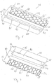
- This plate assembly 22 in turn comprises a central plate 24, which bridges the essential extension region between the two rails 12, 14. In its two lateral end regions 26, 28, this central plate 24 is supported on supporting plates 30 laid in the longitudinal direction of the rails 12, 14. These are so shaped that, when supported on a respective rail foot 32 on the one hand and on the sleepers 16 on the other hand, they provide a support top 34 that is substantially uninterrupted in the longitudinal direction of the rails 12, 14.
- the individual fastening devices 18 are in this way encapsulated or obscured.
- the central plate 24 may be formed so that it not only in its two end portions 26, 28 is supported on the respective support plates 30, but for example in their extension region between them along the rails 12, 14 itself extending support plates 30 also on the ground, in particular the threshold 16 comes to rest.
- the central plate 24 is in each case connected to a rail connecting plate 36, 38.
- These rail connection plates 36, 38, together with the central plate 24, provide a passable surface 40, the height of which is approximately at the same level as the railable surface 42 of the respective rail heads 44 the rail connection plates 36, 38 down from both the central plate 24 and the support plates 30 and reach on their top directly to the rail heads 44 zoom. That is, there is no space for receiving a wheel rim in the interior between the two rails 12, 14 and adjacent to the rail heads 44.
- a surface or top 40 is created, which passes over the entire width away in conjunction with the tops 42 of the rail heads 44. This is especially where the track system 10 is to cross with vehicles with relatively narrow wheels, such as bicycles or wheelchairs, of elementary advantage.
- the rail connecting plate 36 has two transverse to the rail longitudinal direction L substantially adjacent functional areas. On the one hand, in a section to be positioned adjacent to a rail or a rail head 44, this is a deformation region 46, and on the other hand, in an area to be positioned adjacent to the central plate 24, an engagement formation 48, which is referred to below as the second engagement formation 48. In association with this second engagement formation 48, the central plate 24 is explained in more detail and, for example, in FIG Fig. 8 recognizable first engagement formation 50 on.
- the deformation region 46 of the rail connection plate 36 is therefore sufficient, as in Fig. 1 clearly visible until zoom directly to the rail head 44 of the rail 12 zoom.
- this deformation region 46 is to be divided into two regions, namely an upper region 52 and a downwardly adjoining lower region 54.
- the upper region 52 is constructed of solid material, thus has substantially no air pockets, openings or recesses and finally provides the Connection to the remaining part of the rail connection plate 36 ready.
- a connecting lip 56 which makes contact laterally with the rail head 44 is provided in the upper region 52, which ensures that the upper region 52 or the rail connecting plate 36 not only reaches close to the rail head 44 but can also contact it and thus has a substantially gap-free Graduation provides.
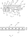
- the subregion 54 is formed with a plurality of support projections 58.
- These support projections 58 are in the exemplary embodiment provided here as in Fig. 6 clearly visible Abstützwandungen 60 formed in the direction from top to bottom, ie in the direction of the upper region 52 away, have a decreasing wall thickness and adjoin each other so that a self-contained wall pattern is generated.
- respective cavities 62 are enclosed or limited by these Abstützwandungen, which in cross-section due to the relative positioning of the end walls 60 a polygonal, have hexagonal geometry here.
- the conclusion is realized at the top with a curved, dome-shaped geometry 64. In this way, defined break points are avoided by avoiding corners and edges following the top portion 52 and providing rounded transitions.
- a plurality of laterally open cavities 62 ' is formed, wherein between each two such laterally open cavities 62' is an end wall 60th lies.
- a retaining projection 68 is provided with barb-like contour. All of these retaining projections 68 form in their entirety a holding formation 69, which in or after positioning a rail connecting plate 36 adjacent to a rail, the respective rail head 44 in Fig. 9 recognizable manner under attack and thus ensure in the rail near end that the rail connection plate 36 is firmly anchored to the rail or the rail head 44.
- a recess 70 which is open at the bottom and is continuous in the longitudinal direction L, is provided in the rail connection plate 36.
- This recess 70 has various functions. On the one hand, it allows the sub-region 54 to fulfill its elastic function in an optimal manner in the manner explained below.
- a weakening region 72 that runs through in the longitudinal direction, ie the rail longitudinal direction L, is formed, which in the event of excessive stress on such a rail connection plate 36 for a defined separation of the deformation region 46 from the remaining region, in particular the second engagement formation 48 realized.
- the recess 70 is bounded by a solid support web 74.
- This support web 74 ends flush with the lower region 54 on its underside, so that it, like the lower region 54, can be supported on the upper side 34 of an associated support plate 30.
- the second engagement formation 48 comprises an engagement head 76 which protrudes downwards from the extension 52 of the upper region 52 which extends into the region of the second engagement formation 48 and at a distance from the support web 74.
- On the engagement head 76 a laterally projecting and projecting in the direction away from the rail engagement projection 78 is formed. This extends as well as the engaging head 76 preferably uninterrupted over the entire length of the rail connecting plate 36.
- a recess or recess 80 is formed, for example, at both lying in the longitudinal direction L end portions of the rail connecting plate 36 by a respective end wall 82, 84 is limited.
- the engaging head 76 On one of its side facing the recess 80, the engaging head 76 has a locking formation 83 in the form of a plurality of barb-like locking projections 85.
- a locking formation 83 in the form of a plurality of barb-like locking projections 85.
- the first engagement formation 50 configured in association with the rail connection plate 36 or its second engagement formation 48 on the central plate 24 has a centering head 86.
- This is designed on the central plate 24 preferably as in the longitudinal direction L continuously continuous profile and is in coordination with the longitudinal extent of the recess 80 between the two end walls 82, 84th dimensioned. That is, in the in Fig. 9 recognizable state in which the central plate 24 is joined to the rail connecting plate 36, engages the centering 86 in the recess 80 so that the two end walls 82, 84 in the longitudinal direction L immediately follow the centering head 86 and thus ensure that the Rail terminal plate 36 can not move with respect to the central plate 24 in the longitudinal direction L.
- an engagement recess 90 which is essentially open to the side but slightly overlapped by the centering head 86 is provided. This is preferably shaped and dimensioned so that it can engage with the engagement projection 78 of the second engagement formation 48 substantially free of play. Furthermore, a counter-locking formation 92, for example in the form of a barb-like profile 94 running through in the longitudinal direction L, is formed on the region of the centering head 86 lying opposite the engagement recess 90. This profile 94 is engaged by the locking projections 85 on the engagement head 76 after establishing the coupling state.
- the engagement head 76 is thus in the manufactured KopplungstSh at its two lateral regions with the central plate 24 and the first engagement formation 50 fomschlüssig coupled. On the rail remote side this is realized by the engagement of the engagement projection 78 in the engagement recess 90. On the rail side positioned this is realized by the engagement of the locking formation 83 with the counter-Arretierformation 92.
- the effective in the rail longitudinal direction L positive locking realized by the concerns of the centering head 86 at the two end walls 82, 84.
- the production costs are a significant competitive factor, is looking for building materials, on the one hand, the growing requirements are met, on the other hand, but also ensure cost-effective manufacturability.
- the central plate 24 is therefore preferably a structure provided by recycling, for example, scrap tires Altgummigranulat provided this Altgummigranulat is bound by Neugummimaterial so that when using appropriate shapes and at high temperature and high pressure comparatively inexpensive plates can be created, which also large Can absorb loads.
- FIGS. 8 and 9 Before the functionality of the track transition device 20 according to the invention is explained below, it will first be described with reference to FIGS. 8 and 9 how a track transition device 20 according to the invention is constructed.
- the support plates 30 are laid along the rails 12 and 14, respectively.
- these support plates 30, for example, so dimensioned be that in each case between two fastening means 18, such a support plate 30 is positioned.
- L longer dimensioned support plates 30 can be used.
- the successive in the longitudinal direction L central plates 24 are then laid, the in Fig. 1 recognizable openings 94, 96 serve to receive clamping elements, such as tie rods, through which the successive in the longitudinal direction L central plates 24 are clamped together to form a composite.
- a connection to the ground, for example the sleepers 16 can take place either in the area of these tension rods or in the end regions of such a track transition device.
- the individual rail connection plates 36 and 38 are mounted.
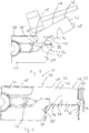
- the procedure is such that, as in Fig. 8 can be seen, the rail connection plates, here the rail connection plate 36, first in a sliding pivoting movement with its engaging head 76 and the engagement projection 78 in the formed between the centering head 86 and the remaining portion of the central plate 24, upwardly open recess can be inserted.
- This Schiebeschwenkamba with which then the engagement projection 78 is immersed in the engagement recess 90, can be supported by hammer blows, with the forces occurring here, the engagement head 76 slides on the convexly curved top of the centering head 86 on the central plate 24.
- the centering head 86 then plunges into the recess 80 formed in the rail connection plate 36, wherein due to the material elasticities present, the engagement formation 83 first moves over the counter-engagement formation 92 until it reaches the position shown in FIG Fig. 9 recognizable mounting position this then engages behind.
- the deformation region 46 also moves downwards along a rail head 44, taking advantage of the elasticity of the deformation region 46 and due to the contact of the Holding projections 68 is compressed laterally with the rail head 44 of the deformation region 46.
- the retaining projections 68 reach under the rail head 44 and thus ensure that a firm connection of the rail connection plate 36 takes place not only in the area close to the central panel, but also in the central area rail-near area.
- the deformation region 46 lies with its lower region 54 on the support plate 30.
- the support web 74 rests on the support plate 30, and the connection lip 56 bears laterally on the rail head 44.
- a practically seamlessly continuous surface is provided, namely by the overall surface 40 of the plate assembly 22 on the one hand, and the tops 42 of the rails 14, 12 on the other.
- a surface that continues this total surface can be provided, which then also a connection to the adjacent road, for example, a concrete carriageway or an asphalt pavement, provides.
- the wheel rims displace the deformation regions 46 downwards, ie the upper region 52 is lowered by being subjected to a wheel rim bent and the Abstweilwandungen 60 allow this deformation by corresponding lateral deflection into the cavities 62. After a wheel rim has moved across a deformation region 46, this will return due to its material elasticity to its original position, as in Fig. 9 is shown.
- the restoring behavior of the upper region 52 contributes to this.
- the restoring behavior of the lower region 54 with its previously deformed Abstweilwandache 60 contributes.
- a defective rail connection plate 36, 38 can be done simply by using a corresponding lever-like tool initially moved out with their holding projections 68 under a rail head 44, if this section of the rail connection plate is still present, and then by further use of a lever-like Tool and the positive engagement of the engagement information 48, 50 is solved. This can be done without any further work having to be carried out on the central plates 24 or the remaining area of the track transition device 20. That is, a single possibly defective rail connection plate 36, 38 can also be replaced as a single component, without having to remove other components of the track transition device 20. This is also facilitated by the fact that in the longitudinal direction L directly successive or abutting rail connection plates 36, 38 have substantially flat end faces, so that no immediate disengagement of individual rail connection plates aggravating form-fitting engagement is generated between immediately adjacent rail connection plates.
- FIG Fig. 10 An alternative embodiment of a track system 10 equipped with a track transition device 20 according to the invention is shown in FIG Fig. 10 shown.
- components which correspond to components described above in terms of construction or function are designated by the same reference numerals.
- the rail connection plates 36 and 38 are constructed as described above. However, there is a difference in the design of the central plate 24. This is not, as shown and described in the embodiment described above, made of elastic material, so for example rubber material, but is made of relatively hard material such. B. concrete material, constructed.
- the central plate 24 of in Fig. 10 In principle, it does not or does not necessarily rest on the sleepers 16, but it cantilevers the area between the rails 12, 14. In its rail-side areas 26, 28, the central plate 24 lies with the substrate 30 'for supporting the rail connection plates 36 , 38 providing sections 100, 102 on the rail feet 104 of the rails 12, 14 on.
- elastic intermediate layer elements 106 may be provided to avoid direct contact of the concrete material of the central plate 24 with the barn material of the rails 12, 14.
- the first engaging formation 50 is provided in the central plate 24, as in the previously described embodiment, although here the flexibility required for the connection is due to the structure alone the rail connection plates 36, 38 is provided from flexible material.
- FIG. 11 Another embodiment variant is in Fig. 11 shown.
- the central plate 24 again bridges over the area between the two rails 12, 14 and lies, for example, on the rail feet .104 via elastic intermediate layer elements 106.
- the central plate 24 is formed in this embodiment variant, however, with two plate layers or plate areas.
- an upper plate layer 108 is constructed of the same material as that described with reference to FIGS Fig. 1 to 9 described central plate. So here rubber material, preferably obtained by the reprocessing of waste tire material rubber granules, can be used to build the top plate layer 108.
- the first engagement formation 50 is then formed again, as described above with respect to the 8 and 9 described and can be brought into engagement with the second engagement formation 48 on the respective rail connecting plate 36, 38.
- the essential supporting function here assumes a lower plate layer 110, for example, made of metal material, such.
- a lower plate layer 110 for example, made of metal material, such.
- profile parts 112 are provided for support on the rail feet 104 and formed and continue to provide the substrate 30 ', on which the rail connection plates 36, 38 can be supported with the lower portion 54 and the support web 74.
- Profile parts 112 extend carrier parts 114, which may be firmly connected to the profile parts 112, for example by welding and on which the upper plate layer 108, so the built of elastic material plate layer rests.
- this upper plate layer 108 is held by the upwardly projecting over the carrier 114 profile parts 112.
- Also in the rail longitudinal direction can be provided by form-fitting engagement a displacement protection for the upper plate layer 108 with respect to the lower plate layer 110.
- the division of the upper plate layer 108 which is primarily adapted to the pitch or longitudinal dimension of the rail connection plates 36, 38 substantially independent of the pitch of the lower plate layer 110.
- the lower plate layer 110 also from other material than metal material, for example, be constructed of concrete material.
- the cohesion of the central plates 24 in the 10 and 11 illustrated embodiments may be made as in the foregoing with reference to the Fig. 1 to 9 described embodiment.
- openings 94, 96 may be provided through which clamping elements are passed and provide a mutual connection of the successive in the rail longitudinal direction of the central plates 24.
- an inventive Plate assembly 22 are provided with the rail connection plates 36, 38, while in other areas, in which the direct connection to the inside of the Schienengrope 44 is not mandatory, conventional, for example, completely constructed of the material of the central plate 24 track transition plates can be used.
- the surface properties of the plate assemblies 22 according to the invention can also be adapted to the requirements arising both in the region of the rail connection plates 36, 38 and in the region of the central plate 24 by virtue of their structural nature, material properties or by adding friction-increasing components.
Landscapes
- Engineering & Computer Science (AREA)
- Architecture (AREA)
- Civil Engineering (AREA)
- Structural Engineering (AREA)
- Road Paving Structures (AREA)
- Coupling Device And Connection With Printed Circuit (AREA)
- Electrical Discharge Machining, Electrochemical Machining, And Combined Machining (AREA)
- Fuses (AREA)
Priority Applications (2)
| Application Number | Priority Date | Filing Date | Title |
|---|---|---|---|
| PL06829861T PL1963577T3 (pl) | 2005-12-22 | 2006-12-22 | Zespół płytowy i urządzenie do przechodzenia przez tory z zespołem płytowym |
| HRP20191112TT HRP20191112T1 (hr) | 2005-12-22 | 2006-12-22 | Ugradna skupina ploča i uređaj za željezničko-cestovni prijelaz s ugradnom skupinom ploča |
Applications Claiming Priority (2)
| Application Number | Priority Date | Filing Date | Title |
|---|---|---|---|
| DE102005061564A DE102005061564A1 (de) | 2005-12-22 | 2005-12-22 | Plattenbaugruppe und Gleisübergangseinrichtung mit einer Plattenbaugruppe |
| PCT/EP2006/012489 WO2007076981A1 (de) | 2005-12-22 | 2006-12-22 | Plattenbaugruppe und gleisübergangseinrichtung mit einer plattenbaugruppe |
Publications (2)
| Publication Number | Publication Date |
|---|---|
| EP1963577A1 EP1963577A1 (de) | 2008-09-03 |
| EP1963577B1 true EP1963577B1 (de) | 2019-06-12 |
Family
ID=37772822
Family Applications (1)
| Application Number | Title | Priority Date | Filing Date |
|---|---|---|---|
| EP06829861.1A Active EP1963577B1 (de) | 2005-12-22 | 2006-12-22 | Plattenbaugruppe und gleisübergangseinrichtung mit einer plattenbaugruppe |
Country Status (8)
| Country | Link |
|---|---|
| EP (1) | EP1963577B1 (pl) |
| AU (1) | AU2006332098B2 (pl) |
| DE (1) | DE102005061564A1 (pl) |
| ES (1) | ES2744207T3 (pl) |
| HR (1) | HRP20191112T1 (pl) |
| HU (1) | HUE046309T2 (pl) |
| PL (1) | PL1963577T3 (pl) |
| WO (1) | WO2007076981A1 (pl) |
Citations (1)
| Publication number | Priority date | Publication date | Assignee | Title |
|---|---|---|---|---|
| DE20101567U1 (de) * | 2001-01-30 | 2001-04-19 | INTERVIA GmbH & Co. KG, 83059 Kolbermoor | Formkörper zur Errichtung eines Gleisübergangs |
Family Cites Families (5)
| Publication number | Priority date | Publication date | Assignee | Title |
|---|---|---|---|---|
| US3465963A (en) * | 1967-12-29 | 1969-09-09 | Goodyear Tire & Rubber | Crossing structure |
| DE4229289A1 (de) * | 1992-09-02 | 1994-03-10 | Kraiburg Gummi Dev Gmbh | Gleisübergangseinrichtung, Formkörper für eine Gleisübergangseinrichtung und Verfahren zur Herstellung eines Formkörpers für eine Gleisübergangseinrichtung |
| AT405426B (de) * | 1996-06-11 | 1999-08-25 | Gmundner Fertigteile Gmbh | Schienengleiche eindeckung für gleise |
| GB0125065D0 (en) * | 2001-10-18 | 2001-12-12 | Performance Polymers Inc | Between-rails roadway for road-rail crossings |
| DE102004043240A1 (de) | 2004-09-07 | 2006-04-06 | Gummiwerk Kraiburg Elastik Gmbh | Gleisübergangseinrichtung |
-
2005
- 2005-12-22 DE DE102005061564A patent/DE102005061564A1/de not_active Ceased
-
2006
- 2006-12-22 ES ES06829861T patent/ES2744207T3/es active Active
- 2006-12-22 PL PL06829861T patent/PL1963577T3/pl unknown
- 2006-12-22 AU AU2006332098A patent/AU2006332098B2/en not_active Ceased
- 2006-12-22 HU HUE06829861A patent/HUE046309T2/hu unknown
- 2006-12-22 EP EP06829861.1A patent/EP1963577B1/de active Active
- 2006-12-22 WO PCT/EP2006/012489 patent/WO2007076981A1/de not_active Ceased
- 2006-12-22 HR HRP20191112TT patent/HRP20191112T1/hr unknown
Patent Citations (1)
| Publication number | Priority date | Publication date | Assignee | Title |
|---|---|---|---|---|
| DE20101567U1 (de) * | 2001-01-30 | 2001-04-19 | INTERVIA GmbH & Co. KG, 83059 Kolbermoor | Formkörper zur Errichtung eines Gleisübergangs |
Also Published As
| Publication number | Publication date |
|---|---|
| PL1963577T3 (pl) | 2019-12-31 |
| WO2007076981A1 (de) | 2007-07-12 |
| EP1963577A1 (de) | 2008-09-03 |
| DE102005061564A1 (de) | 2007-06-28 |
| HUE046309T2 (hu) | 2020-02-28 |
| HRP20191112T1 (hr) | 2019-10-18 |
| ES2744207T3 (es) | 2020-02-24 |
| AU2006332098A1 (en) | 2007-07-12 |
| AU2006332098B2 (en) | 2012-01-19 |
Similar Documents
| Publication | Publication Date | Title |
|---|---|---|
| EP2483477B1 (de) | Vorrichtung zur überbrückung einer dehnfuge | |
| DE2617341A1 (de) | Fugendichtung fuer strassendecken | |
| AT391499B (de) | Eisenbahnoberbau, insbesondere fuer schienenfahrzeuge mit sehr hohen fahrgeschwindigkeiten | |
| EP1200676B2 (de) | Gleis für schienengebundene fahrzeuge | |
| EP0542782B1 (de) | Schienengleicher bahnübergang | |
| DE3809466A1 (de) | Oberbau fuer schienenbahnen | |
| AT404266B (de) | Schienengleicher bahnübergang | |
| EP1206599B1 (de) | Dämpfungsprofil für rillenschienen | |
| EP1963577B1 (de) | Plattenbaugruppe und gleisübergangseinrichtung mit einer plattenbaugruppe | |
| EP1045069A2 (de) | Schotterloser Oberbau mit vorgefertigten Betontragplatten sowie Verfahren zum Ersatz derselben | |
| EP1637653B1 (de) | Quer-Abstützanordnung für Gleisübergangseinrichtung | |
| AT508574B1 (de) | Feste fahrbahn für schienengebundene fahrzeuge | |
| EP2119828A2 (de) | Gleisabdecksystem und Maschine zur Demontage und Verlegung eines Gleisabdecksystems | |
| DE10237176B4 (de) | Fahrbahn für Magnetbahnzüge | |
| DE102022110698A1 (de) | Schiene mit einer verfüllten Schienenrille | |
| DE2222429A1 (de) | Strassenfugendichtung und Enddammanordnung | |
| DE202013101195U1 (de) | Fahrbahnübergang | |
| DE102009044841B4 (de) | Schienenfuge | |
| AT375699B (de) | Schienenanordnung, insbesondere fuer strassenbahn- gleise | |
| EP1735500B1 (de) | Vorgefertige, schlaff bewehrte tragplatte | |
| DE2905888A1 (de) | Vorrichtung zum ueberbruecken von dehnungsfugen in bauwerken | |
| DE10032437A1 (de) | Verfahren zum Herstellen einer Entgleisungsschutzeinrichtung sowie Entgleisungsschutzeinrichtung für ein Gleis | |
| DE194405C (pl) | ||
| AT413827B (de) | Mit strassen- und schienenfahrzeugen befahrbarer gleisoberbau | |
| EP4273320A1 (de) | Schiene mit einer verfüllten schienenrille |
Legal Events
| Date | Code | Title | Description |
|---|---|---|---|
| PUAI | Public reference made under article 153(3) epc to a published international application that has entered the european phase |
Free format text: ORIGINAL CODE: 0009012 |
|
| 17P | Request for examination filed |
Effective date: 20080609 |
|
| AK | Designated contracting states |
Kind code of ref document: A1 Designated state(s): AT BE BG CH CY CZ DE DK EE ES FI FR GB GR HU IE IS IT LI LT LU LV MC NL PL PT RO SE SI SK TR |
|
| AX | Request for extension of the european patent |
Extension state: HR |
|
| RIN1 | Information on inventor provided before grant (corrected) |
Inventor name: SCHWARTZ, ERWIN Inventor name: BARTOLOMAE, JOHANNES Inventor name: STAEUDNER, REINHARD Inventor name: HOEKE, MATTHIAS Inventor name: GEHMACHER, PETER Inventor name: MOERTL, ANDREAS |
|
| 17Q | First examination report despatched |
Effective date: 20090616 |
|
| RAX | Requested extension states of the european patent have changed |
Extension state: HR Payment date: 20080609 |
|
| RAP1 | Party data changed (applicant data changed or rights of an application transferred) |
Owner name: KRAIBURG STRAIL GMBH & CO. KG |
|
| STAA | Information on the status of an ep patent application or granted ep patent |
Free format text: STATUS: EXAMINATION IS IN PROGRESS |
|
| RIC1 | Information provided on ipc code assigned before grant |
Ipc: E01C 9/04 20060101AFI20181220BHEP Ipc: E01C 9/08 20060101ALN20181220BHEP Ipc: E01B 19/00 20060101ALI20181220BHEP Ipc: E01B 21/00 20060101ALI20181220BHEP |
|
| GRAP | Despatch of communication of intention to grant a patent |
Free format text: ORIGINAL CODE: EPIDOSNIGR1 |
|
| STAA | Information on the status of an ep patent application or granted ep patent |
Free format text: STATUS: GRANT OF PATENT IS INTENDED |
|
| RIC1 | Information provided on ipc code assigned before grant |
Ipc: E01C 9/04 20060101AFI20190111BHEP Ipc: E01B 21/00 20060101ALI20190111BHEP Ipc: E01B 19/00 20060101ALI20190111BHEP Ipc: E01C 9/08 20060101ALN20190111BHEP |
|
| INTG | Intention to grant announced |
Effective date: 20190131 |
|
| RIC1 | Information provided on ipc code assigned before grant |
Ipc: E01C 9/08 20060101ALN20190118BHEP Ipc: E01C 9/04 20060101AFI20190118BHEP Ipc: E01B 21/00 20060101ALI20190118BHEP Ipc: E01B 19/00 20060101ALI20190118BHEP |
|
| GRAS | Grant fee paid |
Free format text: ORIGINAL CODE: EPIDOSNIGR3 |
|
| GRAA | (expected) grant |
Free format text: ORIGINAL CODE: 0009210 |
|
| STAA | Information on the status of an ep patent application or granted ep patent |
Free format text: STATUS: THE PATENT HAS BEEN GRANTED |
|
| AK | Designated contracting states |
Kind code of ref document: B1 Designated state(s): AT BE BG CH CY CZ DE DK EE ES FI FR GB GR HU IE IS IT LI LT LU LV MC NL PL PT RO SE SI SK TR |
|
| AX | Request for extension of the european patent |
Extension state: HR |
|
| REG | Reference to a national code |
Ref country code: GB Ref legal event code: FG4D Free format text: NOT ENGLISH |
|
| REG | Reference to a national code |
Ref country code: CH Ref legal event code: EP Ref country code: CH Ref legal event code: NV Representative=s name: E. BLUM AND CO. AG PATENT- UND MARKENANWAELTE , CH |
|
| REG | Reference to a national code |
Ref country code: AT Ref legal event code: REF Ref document number: 1142691 Country of ref document: AT Kind code of ref document: T Effective date: 20190615 |
|
| REG | Reference to a national code |
Ref country code: HR Ref legal event code: TUEP Ref document number: P20191112 Country of ref document: HR |
|
| REG | Reference to a national code |
Ref country code: DE Ref legal event code: R096 Ref document number: 502006016270 Country of ref document: DE |
|
| REG | Reference to a national code |
Ref country code: IE Ref legal event code: FG4D Free format text: LANGUAGE OF EP DOCUMENT: GERMAN |
|
| REG | Reference to a national code |
Ref country code: SE Ref legal event code: TRGR |
|
| REG | Reference to a national code |
Ref country code: RO Ref legal event code: EPE |
|
| REG | Reference to a national code |
Ref country code: NL Ref legal event code: FP |
|
| REG | Reference to a national code |
Ref country code: HR Ref legal event code: T1PR Ref document number: P20191112 Country of ref document: HR |
|
| REG | Reference to a national code |
Ref country code: LT Ref legal event code: MG4D |
|
| PG25 | Lapsed in a contracting state [announced via postgrant information from national office to epo] |
Ref country code: FI Free format text: LAPSE BECAUSE OF FAILURE TO SUBMIT A TRANSLATION OF THE DESCRIPTION OR TO PAY THE FEE WITHIN THE PRESCRIBED TIME-LIMIT Effective date: 20190612 Ref country code: LT Free format text: LAPSE BECAUSE OF FAILURE TO SUBMIT A TRANSLATION OF THE DESCRIPTION OR TO PAY THE FEE WITHIN THE PRESCRIBED TIME-LIMIT Effective date: 20190612 |
|
| REG | Reference to a national code |
Ref country code: SK Ref legal event code: T3 Ref document number: E 31791 Country of ref document: SK |
|
| PG25 | Lapsed in a contracting state [announced via postgrant information from national office to epo] |
Ref country code: LV Free format text: LAPSE BECAUSE OF FAILURE TO SUBMIT A TRANSLATION OF THE DESCRIPTION OR TO PAY THE FEE WITHIN THE PRESCRIBED TIME-LIMIT Effective date: 20190612 Ref country code: BG Free format text: LAPSE BECAUSE OF FAILURE TO SUBMIT A TRANSLATION OF THE DESCRIPTION OR TO PAY THE FEE WITHIN THE PRESCRIBED TIME-LIMIT Effective date: 20190912 Ref country code: GR Free format text: LAPSE BECAUSE OF FAILURE TO SUBMIT A TRANSLATION OF THE DESCRIPTION OR TO PAY THE FEE WITHIN THE PRESCRIBED TIME-LIMIT Effective date: 20190913 |
|
| REG | Reference to a national code |
Ref country code: HR Ref legal event code: ODRP Ref document number: P20191112 Country of ref document: HR Payment date: 20191205 Year of fee payment: 14 |
|
| PG25 | Lapsed in a contracting state [announced via postgrant information from national office to epo] |
Ref country code: PT Free format text: LAPSE BECAUSE OF FAILURE TO SUBMIT A TRANSLATION OF THE DESCRIPTION OR TO PAY THE FEE WITHIN THE PRESCRIBED TIME-LIMIT Effective date: 20191014 Ref country code: EE Free format text: LAPSE BECAUSE OF FAILURE TO SUBMIT A TRANSLATION OF THE DESCRIPTION OR TO PAY THE FEE WITHIN THE PRESCRIBED TIME-LIMIT Effective date: 20190612 |
|
| REG | Reference to a national code |
Ref country code: ES Ref legal event code: FG2A Ref document number: 2744207 Country of ref document: ES Kind code of ref document: T3 Effective date: 20200224 |
|
| PG25 | Lapsed in a contracting state [announced via postgrant information from national office to epo] |
Ref country code: IS Free format text: LAPSE BECAUSE OF FAILURE TO SUBMIT A TRANSLATION OF THE DESCRIPTION OR TO PAY THE FEE WITHIN THE PRESCRIBED TIME-LIMIT Effective date: 20191012 |
|
| REG | Reference to a national code |
Ref country code: HU Ref legal event code: AG4A Ref document number: E046309 Country of ref document: HU |
|
| REG | Reference to a national code |
Ref country code: DE Ref legal event code: R097 Ref document number: 502006016270 Country of ref document: DE |
|
| PG25 | Lapsed in a contracting state [announced via postgrant information from national office to epo] |
Ref country code: TR Free format text: LAPSE BECAUSE OF FAILURE TO SUBMIT A TRANSLATION OF THE DESCRIPTION OR TO PAY THE FEE WITHIN THE PRESCRIBED TIME-LIMIT Effective date: 20190612 |
|
| PLBE | No opposition filed within time limit |
Free format text: ORIGINAL CODE: 0009261 |
|
| STAA | Information on the status of an ep patent application or granted ep patent |
Free format text: STATUS: NO OPPOSITION FILED WITHIN TIME LIMIT |
|
| PG25 | Lapsed in a contracting state [announced via postgrant information from national office to epo] |
Ref country code: DK Free format text: LAPSE BECAUSE OF FAILURE TO SUBMIT A TRANSLATION OF THE DESCRIPTION OR TO PAY THE FEE WITHIN THE PRESCRIBED TIME-LIMIT Effective date: 20190612 |
|
| 26N | No opposition filed |
Effective date: 20200313 |
|
| PG25 | Lapsed in a contracting state [announced via postgrant information from national office to epo] |
Ref country code: SI Free format text: LAPSE BECAUSE OF FAILURE TO SUBMIT A TRANSLATION OF THE DESCRIPTION OR TO PAY THE FEE WITHIN THE PRESCRIBED TIME-LIMIT Effective date: 20190612 Ref country code: IS Free format text: LAPSE BECAUSE OF FAILURE TO SUBMIT A TRANSLATION OF THE DESCRIPTION OR TO PAY THE FEE WITHIN THE PRESCRIBED TIME-LIMIT Effective date: 20200224 |
|
| PG2D | Information on lapse in contracting state deleted |
Ref country code: IS |
|
| PG25 | Lapsed in a contracting state [announced via postgrant information from national office to epo] |
Ref country code: IS Free format text: LAPSE BECAUSE OF FAILURE TO SUBMIT A TRANSLATION OF THE DESCRIPTION OR TO PAY THE FEE WITHIN THE PRESCRIBED TIME-LIMIT Effective date: 20191112 |
|
| PG25 | Lapsed in a contracting state [announced via postgrant information from national office to epo] |
Ref country code: MC Free format text: LAPSE BECAUSE OF FAILURE TO SUBMIT A TRANSLATION OF THE DESCRIPTION OR TO PAY THE FEE WITHIN THE PRESCRIBED TIME-LIMIT Effective date: 20190612 |
|
| PG25 | Lapsed in a contracting state [announced via postgrant information from national office to epo] |
Ref country code: IE Free format text: LAPSE BECAUSE OF NON-PAYMENT OF DUE FEES Effective date: 20191222 |
|
| REG | Reference to a national code |
Ref country code: HR Ref legal event code: ODRP Ref document number: P20191112 Country of ref document: HR Payment date: 20201216 Year of fee payment: 15 |
|
| PG25 | Lapsed in a contracting state [announced via postgrant information from national office to epo] |
Ref country code: CY Free format text: LAPSE BECAUSE OF FAILURE TO SUBMIT A TRANSLATION OF THE DESCRIPTION OR TO PAY THE FEE WITHIN THE PRESCRIBED TIME-LIMIT Effective date: 20190612 |
|
| REG | Reference to a national code |
Ref country code: HR Ref legal event code: ODRP Ref document number: P20191112 Country of ref document: HR Payment date: 20211221 Year of fee payment: 16 |
|
| PGFP | Annual fee paid to national office [announced via postgrant information from national office to epo] |
Ref country code: LU Payment date: 20211222 Year of fee payment: 16 Ref country code: SK Payment date: 20211221 Year of fee payment: 16 Ref country code: SE Payment date: 20211221 Year of fee payment: 16 Ref country code: RO Payment date: 20211209 Year of fee payment: 16 Ref country code: CZ Payment date: 20211221 Year of fee payment: 16 |
|
| PGFP | Annual fee paid to national office [announced via postgrant information from national office to epo] |
Ref country code: HU Payment date: 20211218 Year of fee payment: 16 Ref country code: BE Payment date: 20211221 Year of fee payment: 16 |
|
| PGFP | Annual fee paid to national office [announced via postgrant information from national office to epo] |
Ref country code: PL Payment date: 20211209 Year of fee payment: 16 |
|
| PGFP | Annual fee paid to national office [announced via postgrant information from national office to epo] |
Ref country code: IT Payment date: 20211224 Year of fee payment: 16 |
|
| REG | Reference to a national code |
Ref country code: HR Ref legal event code: PBON Ref document number: P20191112 Country of ref document: HR Effective date: 20221222 |
|
| PG25 | Lapsed in a contracting state [announced via postgrant information from national office to epo] |
Ref country code: RO Free format text: LAPSE BECAUSE OF NON-PAYMENT OF DUE FEES Effective date: 20221222 Ref country code: CZ Free format text: LAPSE BECAUSE OF NON-PAYMENT OF DUE FEES Effective date: 20221222 |
|
| REG | Reference to a national code |
Ref country code: SE Ref legal event code: EUG |
|
| REG | Reference to a national code |
Ref country code: SK Ref legal event code: MM4A Ref document number: E 31791 Country of ref document: SK Effective date: 20221222 |
|
| REG | Reference to a national code |
Ref country code: BE Ref legal event code: MM Effective date: 20221231 |
|
| PG25 | Lapsed in a contracting state [announced via postgrant information from national office to epo] |
Ref country code: LU Free format text: LAPSE BECAUSE OF NON-PAYMENT OF DUE FEES Effective date: 20221222 |
|
| PG25 | Lapsed in a contracting state [announced via postgrant information from national office to epo] |
Ref country code: SE Free format text: LAPSE BECAUSE OF NON-PAYMENT OF DUE FEES Effective date: 20221223 |
|
| PG25 | Lapsed in a contracting state [announced via postgrant information from national office to epo] |
Ref country code: SK Free format text: LAPSE BECAUSE OF NON-PAYMENT OF DUE FEES Effective date: 20221222 Ref country code: BE Free format text: LAPSE BECAUSE OF NON-PAYMENT OF DUE FEES Effective date: 20221231 |
|
| PG25 | Lapsed in a contracting state [announced via postgrant information from national office to epo] |
Ref country code: IT Free format text: LAPSE BECAUSE OF NON-PAYMENT OF DUE FEES Effective date: 20221222 |
|
| PG25 | Lapsed in a contracting state [announced via postgrant information from national office to epo] |
Ref country code: HU Free format text: LAPSE BECAUSE OF NON-PAYMENT OF DUE FEES Effective date: 20221223 |
|
| PG25 | Lapsed in a contracting state [announced via postgrant information from national office to epo] |
Ref country code: PL Free format text: LAPSE BECAUSE OF NON-PAYMENT OF DUE FEES Effective date: 20221222 |
|
| PG25 | Lapsed in a contracting state [announced via postgrant information from national office to epo] |
Ref country code: HU Free format text: LAPSE BECAUSE OF NON-PAYMENT OF DUE FEES Effective date: 20231223 |
|
| PG25 | Lapsed in a contracting state [announced via postgrant information from national office to epo] |
Ref country code: HU Free format text: LAPSE BECAUSE OF NON-PAYMENT OF DUE FEES Effective date: 20231223 |
|
| PG25 | Lapsed in a contracting state [announced via postgrant information from national office to epo] |
Ref country code: HU Free format text: LAPSE BECAUSE OF NON-PAYMENT OF DUE FEES Effective date: 20221223 |
|
| REG | Reference to a national code |
Ref country code: CH Ref legal event code: U11 Free format text: ST27 STATUS EVENT CODE: U-0-0-U10-U11 (AS PROVIDED BY THE NATIONAL OFFICE) Effective date: 20260101 |
|
| PGFP | Annual fee paid to national office [announced via postgrant information from national office to epo] |
Ref country code: DE Payment date: 20251211 Year of fee payment: 20 |
|
| PGFP | Annual fee paid to national office [announced via postgrant information from national office to epo] |
Ref country code: GB Payment date: 20251219 Year of fee payment: 20 |
|
| PGFP | Annual fee paid to national office [announced via postgrant information from national office to epo] |
Ref country code: AT Payment date: 20251222 Year of fee payment: 20 |
|
| PGFP | Annual fee paid to national office [announced via postgrant information from national office to epo] |
Ref country code: NL Payment date: 20251219 Year of fee payment: 20 Ref country code: FR Payment date: 20251222 Year of fee payment: 20 |
|
| PGFP | Annual fee paid to national office [announced via postgrant information from national office to epo] |
Ref country code: ES Payment date: 20260130 Year of fee payment: 20 |
|
| PGFP | Annual fee paid to national office [announced via postgrant information from national office to epo] |
Ref country code: CH Payment date: 20260101 Year of fee payment: 20 |