EP1963451B1 - Release liner for pressure sensitive adhesives and method of use - Google Patents
Release liner for pressure sensitive adhesives and method of use Download PDFInfo
- Publication number
- EP1963451B1 EP1963451B1 EP06839438.6A EP06839438A EP1963451B1 EP 1963451 B1 EP1963451 B1 EP 1963451B1 EP 06839438 A EP06839438 A EP 06839438A EP 1963451 B1 EP1963451 B1 EP 1963451B1
- Authority
- EP
- European Patent Office
- Prior art keywords
- adhesive tape
- layer
- adhesive
- release
- delaminatable
- Prior art date
- Legal status (The legal status is an assumption and is not a legal conclusion. Google has not performed a legal analysis and makes no representation as to the accuracy of the status listed.)
- Active
Links
- 239000004820 Pressure-sensitive adhesive Substances 0.000 title claims description 92
- 238000000034 method Methods 0.000 title claims description 35
- 239000002390 adhesive tape Substances 0.000 claims description 140
- 239000000853 adhesive Substances 0.000 claims description 97
- 230000001070 adhesive effect Effects 0.000 claims description 97
- 239000000758 substrate Substances 0.000 claims description 38
- 239000003973 paint Substances 0.000 claims description 2
- 239000010410 layer Substances 0.000 description 310
- 239000000463 material Substances 0.000 description 62
- -1 polyethylene terephthalate Polymers 0.000 description 25
- 229920002397 thermoplastic olefin Polymers 0.000 description 24
- 229920001684 low density polyethylene Polymers 0.000 description 23
- 239000004702 low-density polyethylene Substances 0.000 description 22
- 229920001296 polysiloxane Polymers 0.000 description 20
- 239000004698 Polyethylene Substances 0.000 description 14
- 239000004743 Polypropylene Substances 0.000 description 13
- 239000006260 foam Substances 0.000 description 13
- 230000000712 assembly Effects 0.000 description 12
- 238000000429 assembly Methods 0.000 description 12
- 238000002844 melting Methods 0.000 description 10
- 230000008018 melting Effects 0.000 description 10
- 238000012360 testing method Methods 0.000 description 10
- 239000000203 mixture Substances 0.000 description 8
- 229920000573 polyethylene Polymers 0.000 description 8
- 229920000098 polyolefin Polymers 0.000 description 8
- 229920001155 polypropylene Polymers 0.000 description 8
- NIXOWILDQLNWCW-UHFFFAOYSA-N acrylic acid group Chemical group C(C=C)(=O)O NIXOWILDQLNWCW-UHFFFAOYSA-N 0.000 description 7
- 229920000728 polyester Polymers 0.000 description 7
- 239000004952 Polyamide Substances 0.000 description 6
- 239000011248 coating agent Substances 0.000 description 6
- 238000000576 coating method Methods 0.000 description 6
- 229920002647 polyamide Polymers 0.000 description 6
- 229920000139 polyethylene terephthalate Polymers 0.000 description 6
- 239000005020 polyethylene terephthalate Substances 0.000 description 6
- 239000012790 adhesive layer Substances 0.000 description 5
- 229920001903 high density polyethylene Polymers 0.000 description 5
- 230000003116 impacting effect Effects 0.000 description 5
- 229920003229 poly(methyl methacrylate) Polymers 0.000 description 5
- 239000004926 polymethyl methacrylate Substances 0.000 description 5
- 238000012545 processing Methods 0.000 description 5
- 238000000926 separation method Methods 0.000 description 5
- 238000004381 surface treatment Methods 0.000 description 5
- 239000004593 Epoxy Substances 0.000 description 4
- 229920001577 copolymer Polymers 0.000 description 4
- 238000001125 extrusion Methods 0.000 description 4
- 239000004700 high-density polyethylene Substances 0.000 description 4
- 229920001179 medium density polyethylene Polymers 0.000 description 4
- 229920000058 polyacrylate Polymers 0.000 description 4
- 230000008569 process Effects 0.000 description 4
- 239000002904 solvent Substances 0.000 description 4
- 229920001400 block copolymer Polymers 0.000 description 3
- 238000010276 construction Methods 0.000 description 3
- 238000004132 cross linking Methods 0.000 description 3
- NBVXSUQYWXRMNV-UHFFFAOYSA-N fluoromethane Chemical compound FC NBVXSUQYWXRMNV-UHFFFAOYSA-N 0.000 description 3
- 238000003475 lamination Methods 0.000 description 3
- 239000004701 medium-density polyethylene Substances 0.000 description 3
- 239000000155 melt Substances 0.000 description 3
- 229910052751 metal Inorganic materials 0.000 description 3
- 239000002184 metal Substances 0.000 description 3
- 239000000178 monomer Substances 0.000 description 3
- 238000000465 moulding Methods 0.000 description 3
- 229920003023 plastic Polymers 0.000 description 3
- 239000004033 plastic Substances 0.000 description 3
- 229920001200 poly(ethylene-vinyl acetate) Polymers 0.000 description 3
- 229920000642 polymer Polymers 0.000 description 3
- 229920002635 polyurethane Polymers 0.000 description 3
- 239000004814 polyurethane Substances 0.000 description 3
- 238000010998 test method Methods 0.000 description 3
- 229920001634 Copolyester Polymers 0.000 description 2
- 229920002943 EPDM rubber Polymers 0.000 description 2
- 239000002318 adhesion promoter Substances 0.000 description 2
- 229910052782 aluminium Inorganic materials 0.000 description 2
- XAGFODPZIPBFFR-UHFFFAOYSA-N aluminium Chemical compound [Al] XAGFODPZIPBFFR-UHFFFAOYSA-N 0.000 description 2
- 229920006378 biaxially oriented polypropylene Polymers 0.000 description 2
- 239000011127 biaxially oriented polypropylene Substances 0.000 description 2
- 238000005253 cladding Methods 0.000 description 2
- 239000003086 colorant Substances 0.000 description 2
- 230000032798 delamination Effects 0.000 description 2
- 239000004205 dimethyl polysiloxane Substances 0.000 description 2
- 239000005038 ethylene vinyl acetate Substances 0.000 description 2
- 239000012943 hotmelt Substances 0.000 description 2
- 230000006872 improvement Effects 0.000 description 2
- 229920000092 linear low density polyethylene Polymers 0.000 description 2
- 238000012986 modification Methods 0.000 description 2
- 230000004048 modification Effects 0.000 description 2
- 239000000123 paper Substances 0.000 description 2
- 229920000435 poly(dimethylsiloxane) Polymers 0.000 description 2
- 238000002360 preparation method Methods 0.000 description 2
- 238000007789 sealing Methods 0.000 description 2
- 239000007787 solid Substances 0.000 description 2
- 239000000126 substance Substances 0.000 description 2
- 229920001169 thermoplastic Polymers 0.000 description 2
- 229920001187 thermosetting polymer Polymers 0.000 description 2
- 229920001862 ultra low molecular weight polyethylene Polymers 0.000 description 2
- BLDFSDCBQJUWFG-UHFFFAOYSA-N 2-(methylamino)-1,2-diphenylethanol Chemical compound C=1C=CC=CC=1C(NC)C(O)C1=CC=CC=C1 BLDFSDCBQJUWFG-UHFFFAOYSA-N 0.000 description 1
- VEXZGXHMUGYJMC-UHFFFAOYSA-M Chloride anion Chemical compound [Cl-] VEXZGXHMUGYJMC-UHFFFAOYSA-M 0.000 description 1
- 241001643597 Evas Species 0.000 description 1
- 244000043261 Hevea brasiliensis Species 0.000 description 1
- 229920001774 Perfluoroether Polymers 0.000 description 1
- 239000004642 Polyimide Substances 0.000 description 1
- 229920002396 Polyurea Polymers 0.000 description 1
- 229920005830 Polyurethane Foam Polymers 0.000 description 1
- 230000004075 alteration Effects 0.000 description 1
- 230000015572 biosynthetic process Effects 0.000 description 1
- 238000012662 bulk polymerization Methods 0.000 description 1
- DQXBYHZEEUGOBF-UHFFFAOYSA-N but-3-enoic acid;ethene Chemical compound C=C.OC(=O)CC=C DQXBYHZEEUGOBF-UHFFFAOYSA-N 0.000 description 1
- 239000006229 carbon black Substances 0.000 description 1
- 239000003054 catalyst Substances 0.000 description 1
- 239000000919 ceramic Substances 0.000 description 1
- 229910010293 ceramic material Inorganic materials 0.000 description 1
- 238000010382 chemical cross-linking Methods 0.000 description 1
- 238000003851 corona treatment Methods 0.000 description 1
- 238000005520 cutting process Methods 0.000 description 1
- 239000000975 dye Substances 0.000 description 1
- 238000007720 emulsion polymerization reaction Methods 0.000 description 1
- 229920001038 ethylene copolymer Polymers 0.000 description 1
- 239000004744 fabric Substances 0.000 description 1
- 210000004905 finger nail Anatomy 0.000 description 1
- 239000006261 foam material Substances 0.000 description 1
- 239000011888 foil Substances 0.000 description 1
- 238000010030 laminating Methods 0.000 description 1
- 239000004707 linear low-density polyethylene Substances 0.000 description 1
- 239000007788 liquid Substances 0.000 description 1
- 239000007769 metal material Substances 0.000 description 1
- 239000012968 metallocene catalyst Substances 0.000 description 1
- 238000002156 mixing Methods 0.000 description 1
- 229920003052 natural elastomer Polymers 0.000 description 1
- 229920001194 natural rubber Polymers 0.000 description 1
- 239000004745 nonwoven fabric Substances 0.000 description 1
- 229920006285 olefinic elastomer Polymers 0.000 description 1
- 239000005026 oriented polypropylene Substances 0.000 description 1
- UJMWVICAENGCRF-UHFFFAOYSA-N oxygen difluoride Chemical compound FOF UJMWVICAENGCRF-UHFFFAOYSA-N 0.000 description 1
- 239000011941 photocatalyst Substances 0.000 description 1
- 239000000049 pigment Substances 0.000 description 1
- 239000004014 plasticizer Substances 0.000 description 1
- 229920001084 poly(chloroprene) Polymers 0.000 description 1
- 229920000162 poly(ureaurethane) Polymers 0.000 description 1
- 229920001721 polyimide Polymers 0.000 description 1
- 238000006116 polymerization reaction Methods 0.000 description 1
- 239000011496 polyurethane foam Substances 0.000 description 1
- 238000003672 processing method Methods 0.000 description 1
- 230000005855 radiation Effects 0.000 description 1
- 230000008707 rearrangement Effects 0.000 description 1
- 239000001054 red pigment Substances 0.000 description 1
- 229920005989 resin Polymers 0.000 description 1
- 239000011347 resin Substances 0.000 description 1
- 229920003031 santoprene Polymers 0.000 description 1
- SCPYDCQAZCOKTP-UHFFFAOYSA-N silanol Chemical compound [SiH3]O SCPYDCQAZCOKTP-UHFFFAOYSA-N 0.000 description 1
- 239000013464 silicone adhesive Substances 0.000 description 1
- 239000004447 silicone coating Substances 0.000 description 1
- 229920002050 silicone resin Polymers 0.000 description 1
- 239000002356 single layer Substances 0.000 description 1
- 238000006467 substitution reaction Methods 0.000 description 1
- 239000004416 thermosoftening plastic Substances 0.000 description 1
- 238000012546 transfer Methods 0.000 description 1
- XLYOFNOQVPJJNP-UHFFFAOYSA-N water Substances O XLYOFNOQVPJJNP-UHFFFAOYSA-N 0.000 description 1
- 239000002759 woven fabric Substances 0.000 description 1
Images
Classifications
-
- B—PERFORMING OPERATIONS; TRANSPORTING
- B29—WORKING OF PLASTICS; WORKING OF SUBSTANCES IN A PLASTIC STATE IN GENERAL
- B29C—SHAPING OR JOINING OF PLASTICS; SHAPING OF MATERIAL IN A PLASTIC STATE, NOT OTHERWISE PROVIDED FOR; AFTER-TREATMENT OF THE SHAPED PRODUCTS, e.g. REPAIRING
- B29C65/00—Joining or sealing of preformed parts, e.g. welding of plastics materials; Apparatus therefor
- B29C65/48—Joining or sealing of preformed parts, e.g. welding of plastics materials; Apparatus therefor using adhesives, i.e. using supplementary joining material; solvent bonding
- B29C65/50—Joining or sealing of preformed parts, e.g. welding of plastics materials; Apparatus therefor using adhesives, i.e. using supplementary joining material; solvent bonding using adhesive tape, e.g. thermoplastic tape; using threads or the like
- B29C65/5057—Joining or sealing of preformed parts, e.g. welding of plastics materials; Apparatus therefor using adhesives, i.e. using supplementary joining material; solvent bonding using adhesive tape, e.g. thermoplastic tape; using threads or the like positioned between the surfaces to be joined
-
- C—CHEMISTRY; METALLURGY
- C09—DYES; PAINTS; POLISHES; NATURAL RESINS; ADHESIVES; COMPOSITIONS NOT OTHERWISE PROVIDED FOR; APPLICATIONS OF MATERIALS NOT OTHERWISE PROVIDED FOR
- C09J—ADHESIVES; NON-MECHANICAL ASPECTS OF ADHESIVE PROCESSES IN GENERAL; ADHESIVE PROCESSES NOT PROVIDED FOR ELSEWHERE; USE OF MATERIALS AS ADHESIVES
- C09J7/00—Adhesives in the form of films or foils
- C09J7/30—Adhesives in the form of films or foils characterised by the adhesive composition
- C09J7/38—Pressure-sensitive adhesives [PSA]
-
- B—PERFORMING OPERATIONS; TRANSPORTING
- B29—WORKING OF PLASTICS; WORKING OF SUBSTANCES IN A PLASTIC STATE IN GENERAL
- B29C—SHAPING OR JOINING OF PLASTICS; SHAPING OF MATERIAL IN A PLASTIC STATE, NOT OTHERWISE PROVIDED FOR; AFTER-TREATMENT OF THE SHAPED PRODUCTS, e.g. REPAIRING
- B29C65/00—Joining or sealing of preformed parts, e.g. welding of plastics materials; Apparatus therefor
- B29C65/48—Joining or sealing of preformed parts, e.g. welding of plastics materials; Apparatus therefor using adhesives, i.e. using supplementary joining material; solvent bonding
- B29C65/50—Joining or sealing of preformed parts, e.g. welding of plastics materials; Apparatus therefor using adhesives, i.e. using supplementary joining material; solvent bonding using adhesive tape, e.g. thermoplastic tape; using threads or the like
- B29C65/5007—Joining or sealing of preformed parts, e.g. welding of plastics materials; Apparatus therefor using adhesives, i.e. using supplementary joining material; solvent bonding using adhesive tape, e.g. thermoplastic tape; using threads or the like characterised by the structure of said adhesive tape, threads or the like
- B29C65/5021—Joining or sealing of preformed parts, e.g. welding of plastics materials; Apparatus therefor using adhesives, i.e. using supplementary joining material; solvent bonding using adhesive tape, e.g. thermoplastic tape; using threads or the like characterised by the structure of said adhesive tape, threads or the like being multi-layered
-
- C—CHEMISTRY; METALLURGY
- C09—DYES; PAINTS; POLISHES; NATURAL RESINS; ADHESIVES; COMPOSITIONS NOT OTHERWISE PROVIDED FOR; APPLICATIONS OF MATERIALS NOT OTHERWISE PROVIDED FOR
- C09J—ADHESIVES; NON-MECHANICAL ASPECTS OF ADHESIVE PROCESSES IN GENERAL; ADHESIVE PROCESSES NOT PROVIDED FOR ELSEWHERE; USE OF MATERIALS AS ADHESIVES
- C09J7/00—Adhesives in the form of films or foils
- C09J7/40—Adhesives in the form of films or foils characterised by release liners
- C09J7/401—Adhesives in the form of films or foils characterised by release liners characterised by the release coating composition
-
- C—CHEMISTRY; METALLURGY
- C09—DYES; PAINTS; POLISHES; NATURAL RESINS; ADHESIVES; COMPOSITIONS NOT OTHERWISE PROVIDED FOR; APPLICATIONS OF MATERIALS NOT OTHERWISE PROVIDED FOR
- C09J—ADHESIVES; NON-MECHANICAL ASPECTS OF ADHESIVE PROCESSES IN GENERAL; ADHESIVE PROCESSES NOT PROVIDED FOR ELSEWHERE; USE OF MATERIALS AS ADHESIVES
- C09J7/00—Adhesives in the form of films or foils
- C09J7/40—Adhesives in the form of films or foils characterised by release liners
- C09J7/403—Adhesives in the form of films or foils characterised by release liners characterised by the structure of the release feature
-
- B—PERFORMING OPERATIONS; TRANSPORTING
- B29—WORKING OF PLASTICS; WORKING OF SUBSTANCES IN A PLASTIC STATE IN GENERAL
- B29K—INDEXING SCHEME ASSOCIATED WITH SUBCLASSES B29B, B29C OR B29D, RELATING TO MOULDING MATERIALS OR TO MATERIALS FOR MOULDS, REINFORCEMENTS, FILLERS OR PREFORMED PARTS, e.g. INSERTS
- B29K2063/00—Use of EP, i.e. epoxy resins or derivatives thereof, as moulding material
-
- B—PERFORMING OPERATIONS; TRANSPORTING
- B29—WORKING OF PLASTICS; WORKING OF SUBSTANCES IN A PLASTIC STATE IN GENERAL
- B29L—INDEXING SCHEME ASSOCIATED WITH SUBCLASS B29C, RELATING TO PARTICULAR ARTICLES
- B29L2009/00—Layered products
-
- B—PERFORMING OPERATIONS; TRANSPORTING
- B29—WORKING OF PLASTICS; WORKING OF SUBSTANCES IN A PLASTIC STATE IN GENERAL
- B29L—INDEXING SCHEME ASSOCIATED WITH SUBCLASS B29C, RELATING TO PARTICULAR ARTICLES
- B29L2031/00—Other particular articles
- B29L2031/30—Vehicles, e.g. ships or aircraft, or body parts thereof
- B29L2031/3005—Body finishings
-
- C—CHEMISTRY; METALLURGY
- C09—DYES; PAINTS; POLISHES; NATURAL RESINS; ADHESIVES; COMPOSITIONS NOT OTHERWISE PROVIDED FOR; APPLICATIONS OF MATERIALS NOT OTHERWISE PROVIDED FOR
- C09J—ADHESIVES; NON-MECHANICAL ASPECTS OF ADHESIVE PROCESSES IN GENERAL; ADHESIVE PROCESSES NOT PROVIDED FOR ELSEWHERE; USE OF MATERIALS AS ADHESIVES
- C09J2301/00—Additional features of adhesives in the form of films or foils
- C09J2301/10—Additional features of adhesives in the form of films or foils characterized by the structural features of the adhesive tape or sheet
- C09J2301/12—Additional features of adhesives in the form of films or foils characterized by the structural features of the adhesive tape or sheet by the arrangement of layers
- C09J2301/124—Additional features of adhesives in the form of films or foils characterized by the structural features of the adhesive tape or sheet by the arrangement of layers the adhesive layer being present on both sides of the carrier, e.g. double-sided adhesive tape
-
- C—CHEMISTRY; METALLURGY
- C09—DYES; PAINTS; POLISHES; NATURAL RESINS; ADHESIVES; COMPOSITIONS NOT OTHERWISE PROVIDED FOR; APPLICATIONS OF MATERIALS NOT OTHERWISE PROVIDED FOR
- C09J—ADHESIVES; NON-MECHANICAL ASPECTS OF ADHESIVE PROCESSES IN GENERAL; ADHESIVE PROCESSES NOT PROVIDED FOR ELSEWHERE; USE OF MATERIALS AS ADHESIVES
- C09J2301/00—Additional features of adhesives in the form of films or foils
- C09J2301/30—Additional features of adhesives in the form of films or foils characterized by the chemical, physicochemical or physical properties of the adhesive or the carrier
- C09J2301/302—Additional features of adhesives in the form of films or foils characterized by the chemical, physicochemical or physical properties of the adhesive or the carrier the adhesive being pressure-sensitive, i.e. tacky at temperatures inferior to 30°C
-
- C—CHEMISTRY; METALLURGY
- C09—DYES; PAINTS; POLISHES; NATURAL RESINS; ADHESIVES; COMPOSITIONS NOT OTHERWISE PROVIDED FOR; APPLICATIONS OF MATERIALS NOT OTHERWISE PROVIDED FOR
- C09J—ADHESIVES; NON-MECHANICAL ASPECTS OF ADHESIVE PROCESSES IN GENERAL; ADHESIVE PROCESSES NOT PROVIDED FOR ELSEWHERE; USE OF MATERIALS AS ADHESIVES
- C09J2301/00—Additional features of adhesives in the form of films or foils
- C09J2301/40—Additional features of adhesives in the form of films or foils characterized by the presence of essential components
- C09J2301/414—Additional features of adhesives in the form of films or foils characterized by the presence of essential components presence of a copolymer
-
- C—CHEMISTRY; METALLURGY
- C09—DYES; PAINTS; POLISHES; NATURAL RESINS; ADHESIVES; COMPOSITIONS NOT OTHERWISE PROVIDED FOR; APPLICATIONS OF MATERIALS NOT OTHERWISE PROVIDED FOR
- C09J—ADHESIVES; NON-MECHANICAL ASPECTS OF ADHESIVE PROCESSES IN GENERAL; ADHESIVE PROCESSES NOT PROVIDED FOR ELSEWHERE; USE OF MATERIALS AS ADHESIVES
- C09J2427/00—Presence of halogenated polymer
- C09J2427/005—Presence of halogenated polymer in the release coating
-
- C—CHEMISTRY; METALLURGY
- C09—DYES; PAINTS; POLISHES; NATURAL RESINS; ADHESIVES; COMPOSITIONS NOT OTHERWISE PROVIDED FOR; APPLICATIONS OF MATERIALS NOT OTHERWISE PROVIDED FOR
- C09J—ADHESIVES; NON-MECHANICAL ASPECTS OF ADHESIVE PROCESSES IN GENERAL; ADHESIVE PROCESSES NOT PROVIDED FOR ELSEWHERE; USE OF MATERIALS AS ADHESIVES
- C09J2483/00—Presence of polysiloxane
- C09J2483/005—Presence of polysiloxane in the release coating
-
- Y—GENERAL TAGGING OF NEW TECHNOLOGICAL DEVELOPMENTS; GENERAL TAGGING OF CROSS-SECTIONAL TECHNOLOGIES SPANNING OVER SEVERAL SECTIONS OF THE IPC; TECHNICAL SUBJECTS COVERED BY FORMER USPC CROSS-REFERENCE ART COLLECTIONS [XRACs] AND DIGESTS
- Y10—TECHNICAL SUBJECTS COVERED BY FORMER USPC
- Y10T—TECHNICAL SUBJECTS COVERED BY FORMER US CLASSIFICATION
- Y10T428/00—Stock material or miscellaneous articles
- Y10T428/14—Layer or component removable to expose adhesive
- Y10T428/1424—Halogen containing compound
- Y10T428/1429—Fluorine
-
- Y—GENERAL TAGGING OF NEW TECHNOLOGICAL DEVELOPMENTS; GENERAL TAGGING OF CROSS-SECTIONAL TECHNOLOGIES SPANNING OVER SEVERAL SECTIONS OF THE IPC; TECHNICAL SUBJECTS COVERED BY FORMER USPC CROSS-REFERENCE ART COLLECTIONS [XRACs] AND DIGESTS
- Y10—TECHNICAL SUBJECTS COVERED BY FORMER USPC
- Y10T—TECHNICAL SUBJECTS COVERED BY FORMER US CLASSIFICATION
- Y10T428/00—Stock material or miscellaneous articles
- Y10T428/14—Layer or component removable to expose adhesive
- Y10T428/1452—Polymer derived only from ethylenically unsaturated monomer
-
- Y—GENERAL TAGGING OF NEW TECHNOLOGICAL DEVELOPMENTS; GENERAL TAGGING OF CROSS-SECTIONAL TECHNOLOGIES SPANNING OVER SEVERAL SECTIONS OF THE IPC; TECHNICAL SUBJECTS COVERED BY FORMER USPC CROSS-REFERENCE ART COLLECTIONS [XRACs] AND DIGESTS
- Y10—TECHNICAL SUBJECTS COVERED BY FORMER USPC
- Y10T—TECHNICAL SUBJECTS COVERED BY FORMER US CLASSIFICATION
- Y10T428/00—Stock material or miscellaneous articles
- Y10T428/14—Layer or component removable to expose adhesive
- Y10T428/1476—Release layer
Definitions
- This invention relates to release liners.
- the present invention relates to release liners for supporting double-sided pressure sensitive adhesive tapes, sheets, etc. that are rolled-up before being dispensed. More particularly, this invention relates to such release liners that can be readily delaminated or otherwise separated into at least two layers. The present invention also relates to methods of using such release liners.
- Adhesive tapes have been useful in a variety of industrial and automotive applications. Double sided adhesive tapes have been used to bond together a variety of substrates or surfaces and are particularly useful for industrial and automotive applications. Double-sided adhesive tapes having a pressure sensitive adhesive (PSA) on both sides (e.g., in the form of a foam core with a pressure sensitive adhesive on each side) have been found useful in bonding together substrates of similar or dissimilar materials
- PSA pressure sensitive adhesive
- Such double-sided attachment tapes are typically manufactured in wide sheets, laminated onto a release liner of matching width to form an adhesive sheet assembly, and then wound into a roll.
- the resulting wide adhesive roll assembly is then converted or separated (e.g., by slitting) into a plurality of narrower rolls of tape assembly having the same width or varying widths, depending on the intended use(s) of the adhesive tape.
- US 6,506,489 B1 relates to a double faced pressure sensitive adhesive sheet including an inner pressure sensitive adhesive layer.
- the adhesive layer includes aa release liner comprising two internal layers which can be delaminated, namely an outer silicon series release liner and an outer non-silicon series release liner on the opposite side of the sheet from the silicon series release liner.
- the present invention is such an improvement.
- the present invention is directed to an adhesive tape assembly comprising a double-sided adhesive tape having a pressure sensitive adhesive ("PSA") on each side thereof, and a delaminatable release liner attached to one or both outer adhesive surfaces of the double-sided adhesive tape.
- the adhesive tape assembly is capable of forming a roll of tape having superior roll stability (i.e., the rolls are less likely to fall apart when the roll is held suspended along its outer circumferential edge) compared to double coated tape rolls having two liners.
- the present invention satisfies the need for more stable rolls, especially more stable narrow planetary rolls of a tape assembly comprising a double-sided tape with a PSA on each side.
- the present invention also provides a double-sided PSA tape assembly that includes a delaminatable release liner, portions of which may be easily and efficiently removed in a step-wise order to apply the adhesive tape to one or more substrates.
- an exemplary adhesive tape assembly comprises a double-sided adhesive tape comprising front and back adhesive sides, each of the adhesive sides comprising a pressure sensitive adhesive; and a delaminatable release liner in contact with, bonded to and readily removable from at least one of the adhesive sides, the delaminatable release liner comprising a first major release surface on an exposed side of the release liner, a second major release surface on an opposite side of the release liner, and a plane of weakness between the first and second major release surfaces, wherein the release liner can be readily delaminated lengthwise along the plane of weakness, between the first and second major release surfaces, so as to form a first delaminated layer and a second delaminated layer, with the first delaminated layer comprising the first major release surface and a first back side surface opposite the first major release surface, and the second delaminated layer comprising the second major release surface and a second back side surface opposite the second major release surface; wherein the adhesive tape assembly has (i) a first bond
- an exemplary adhesive tape assembly comprises double-sided adhesive tape comprising front and back adhesive sides, wherein each of the adhesive sides comprises a pressure sensitive adhesive; a substrate, wherein the front adhesive side of the double-sided adhesive tape is permanently bonded to a surface of the substrate; and a delaminatable release liner in contact with, bonded to and readily removable from the back adhesive side of the double-sided adhesive tape, the delaminatable release liner comprising a first major release surface on one side of the release liner, a second major release surface on an opposite side of the release liner, and a plane of weakness between the first and second major release surfaces, wherein the release liner can be readily delaminated lengthwise along the plane of weakness, between the first and second major release surfaces, so as to form a first delaminated layer and a second delaminated layer, with the first delaminated layer comprising the first major release surface and a first back side surface opposite the first major release surface, and the second delaminated layer comprising
- the double-sided adhesive tape comprises front and back adhesive sides, with each of the adhesive sides comprising an acrylic or other suitable pressure sensitive adhesive (PSA).
- PSA pressure sensitive adhesive
- the adhesive tape can further comprise an acrylic or other suitable foam core with the front adhesive side and the back adhesive side forming opposite sides thereof.
- Each of the first backing layer and the second backing layer has a release material thereon in the form, for example, of an extruded or laminated layer or a coating in contact with, bonded to and readily removable from at least one of the adhesive sides of the tape.
- the adhesive tape assembly may further include a tab heat bonded or otherwise adhered to at least one of the first and second backing layers upon separation of the first backing layer from the second backing layer or vice versa.
- Each tab is operatively adapted (e.g., dimensioned) to facilitate removal of the backing layer it is bonded to from the adhesive tape by pulling on the tab.
- the adhesive tape assembly can have a width and be wound into a roll, with both release layers (i.e., the first and second release layers) of the delaminatable release liner contacting the outer adhesive surfaces of the adhesive tape with the resulting roll having an outer circumferential edge.
- the diameter of the roll can be, for example, at least 20 times the width of the roll, and the roll not fall apart when held suspended along the outer circumferential edge.
- a method for permanently adhering or otherwise applying a double-sided pressure sensitive adhesive tape to one or more surfaces such as, for example, a surface on a product such as, e.g., an interior or exterior body molding, a window pane, etc. that is to be adhered to a surface on a vehicle (e.g., a body part of an automobile, aircraft, watercraft, etc.) or a building, and other separate surfaces on opposing substrates, etc.
- a surface on a product such as, e.g., an interior or exterior body molding, a window pane, etc. that is to be adhered to a surface on a vehicle (e.g., a body part of an automobile, aircraft, watercraft, etc.) or a building, and other separate surfaces on opposing substrates, etc.
- the method comprises providing an adhesive tape assembly like that described above and herein; exposing the pressure sensitive adhesive of an adhesive side (e.g., by unwinding the adhesive tape assembly) along a length of the adhesive tape assembly; and applying, typically so as to permanently adhere, the exposed pressure sensitive adhesive of the adhesive side of each length of the adhesive tape assembly to a first substrate with the delaminatable release liner positioned over the unexposed pressure sensitive adhesive of the other adhesive side.
- the adhesive tape assembly being provided to be in the form of a planetary or other desired roll.
- the method comprises unwinding the roll to expose the pressure sensitive adhesive of an adhesive side of the adhesive tape assembly, optionally cutting the adhesive tape assembly into discrete sections of desired lengths, and then applying the adhesive tape assembly to a first substrate as described above.
- Each of the discrete lengths can have a length and a width suitable for adhering a component onto a vehicle, building or other substrate.
- the method can further comprise removing at least a portion of an outer portion of the delaminatable release liner (i.e., the first or second delaminated layer) on the one or more lengths of the adhesive tape assembly so as to expose a previously unexposed back side surface of an inner portion (i.e., the second or first delaminated layer) of the delaminatable release liner previously in contact with, bonded to and readily removable from the outer portion. Removing the outer portion of the delaminatable release liner results in an article assembly comprising the first substrate having thereon the adhesive tape covered by an inner portion (i.e., the second or first delaminated layer) of the delaminatable release liner.
- an outer portion of the delaminatable release liner i.e., the first or second delaminated layer
- the article assembly may be further processed (e.g., painted) prior to removal of the inner portion of the delaminatable release liner, and then subsequently bonded to a second substrate by removing the inner portion of the delaminatable release liner and bringing the second substrate into contact with the exposed pressure sensitive adhesive surface on the other adhesive side of each length of the adhesive tape assembly; and applying, typically so as to permanently adhere, the exposed pressure sensitive adhesive of the other adhesive side of each length of the adhesive tape assembly to a second substrate.
- the adhesive tape is applied between, typically so as to permanently adhere together, the first substrate and second substrate.
- the present method can further comprise heat bonding or otherwise adhering a tab to the back side surface of the inner portion (i.e., the second or first delaminated layer) of the delaminatable release liner along one or more lengths of the adhesive tape assembly.
- the tab is adhered sufficiently so as not to detach from the inner portion of the delaminatable release liner before at least a portion of the inner portion of the delaminatable release liner is pulled off of the adhesive tape.
- a tab can be used to at least facilitate the removal of the inner portion of the delaminatable release liner.
- a tab Before or after the outer portion of the delaminatable release liner is removed from the adhesive tape, a tab can be bonded to the inner portion of the delaminatable release liner on the one or more lengths of the adhesive tape assembly.
- the outer portion and the inner portion of the delaminatable release liner are removed one after the other, rather than at the same time, and are removed only after the first exposed adhesive side has been applied, typically so as to permanently adhere, to a first substrate.
- the present method can further comprise removing the inner portion of the delaminatable release liner on the one or more lengths of the adhesive tape assembly by pulling on a tab bonded thereto, so as to expose the other adhesive side of each length of the adhesive tape assembly; and applying, typically so as to permanently adhere, the exposed pressure sensitive adhesive of the other adhesive side of each length of the adhesive tape assembly to a second substrate such as, for example, a surface of a vehicle (e.g., part of an automobile, aircraft or, watercraft), a building, or the like.
- a second substrate such as, for example, a surface of a vehicle (e.g., part of an automobile, aircraft or, watercraft), a building, or the like.
- the adhesive tape can be applied between, typically so as to permanently adhere together, the first substrate and second substrate.
- an exemplary method of applying a double-sided pressure sensitive adhesive tape to one or more surfaces comprises (I) providing an adhesive tape assembly, wherein the adhesive tape assembly comprises a double-sided adhesive tape comprising front and back adhesive sides, each of the adhesive sides comprising a pressure sensitive adhesive; and a delaminatable release liner in contact with, bonded to and readily removable from the back adhesive side of the double-sided adhesive tape, the delaminatable release liner comprising a first major release surface on one side of the release liner, a second major release surface on an opposite side of the release liner, and a plane of weakness between the first and second major release surfaces, wherein the release liner can be readily delaminated lengthwise along the plane of weakness, between the first and second major release surfaces, so as to form a first delaminated layer and a second delaminated layer, with the first delaminated layer comprising the first major release surface and a first back side surface opposite the first major release surface, and the second delaminated layer comprising
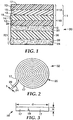
- an exemplary delaminatable release liner 11 is made with at least two delaminatable portions 11A and 11B.
- outer delaminatable portion 11A comprises a first release layer 13 and a first backing layer 15.
- the layers 13 and 15 define a first major release surface 17 and a first back side surface 19 of delaminatable portion 11A, respectively.
- Inner delaminatable portion 11B comprises a second release layer 12 and a second backing layer 14.
- the layers 12 and 14 define a second major release surface 16 and a second back side surface 18 of delaminatable portion 11B, respectively.
- An adhesive tape assembly 20 can be made, according to the present invention, by forming delaminatable release liner 11, and releasably bonding delaminatable release liner 11 to an outer adhesive surface 28 of a double-sided adhesive tape 22.
- the tape 22 includes a front adhesive side or surface 24 defined by a PSA layer 26 of a pressure sensitive adhesive and a back adhesive side or surface 28 defined by a PSA layer 30 of the same or a different pressure sensitive adhesive.
- Delaminatable release liner 11 is in contact with, bonded to and readily removable from PSA layers 30 and 26 when in roll form (see, for example, Fig. 2 ).
- Delaminatable release liner 11 is readily removable from tape 22 such that removal of delaminatable release liner 11 or a portion thereof (e.g., outer delaminatable portion 11A, inner delaminatable portion 11B, or both) does not cause significant damage to double-sided adhesive tape 22 (i.e., does not cause cohesive failure, substantial tearing or substantial permanent stretching of the tape).
- delaminatable release liner 11 or a portion thereof e.g., outer delaminatable portion 11A, inner delaminatable portion 11B, or both
- significant damage to double-sided adhesive tape 22 i.e., does not cause cohesive failure, substantial tearing or substantial permanent stretching of the tape.
- the bond strength between outer delaminatable portion 11A and inner delaminatable portion 11B is desirable for the bond strength between outer delaminatable portion 11A and inner delaminatable portion 11B to be less than the bond strength between inner delaminatable portion 11B and double-sided adhesive tape 22 such that outer delaminatable portion 11A is readily removable from inner delaminatable portion 11B without negatively impacting the bond between inner delaminatable portion 11B and double-sided adhesive tape 22.
- the bond strength between outer delaminatable portion 11A and double-sided adhesive tape 22 i.e., surface 24 of tape 22
- the bond strength between outer delaminatable portion 11A and inner delaminatable portion 11B it is typically desirable for the bond strength between outer delaminatable portion 11A and double-sided adhesive tape 22 (i.e., surface 24 of tape 22) to be less than the bond strength between outer delaminatable portion 11A and inner delaminatable portion 11B such that, when in roll form, outer delaminatable portion 11A releasably separates from double-sided adhesive tape 22 (i.e., surface 24 of tape 22) without negatively impacting the bond between outer delaminatable portion 11A and inner delaminatable portion 11B.
- exemplary adhesive tape assembly 20 may comprise a number of individual layers. A description of possible layers and layer components is provided below.
- Adhesive tape assemblies of the present invention comprise a delaminatable release liner such as exemplary delaminatable release liner 11 of Fig. 1 .
- Each delaminatable release liner comprises first and second backing layers such as first and second backing layers 15 and 14 shown in exemplary delaminatable release liner 11 of Fig. 1 .
- Each backing layer typically comprises a film or foam material that may be formed from a variety of materials.
- the composition and structure (e.g., thickness) of each backing layer is chosen so as to provide sufficient tensile and tear strength to the backing layers so that the backing layers may be releasably removed from the adhesive tape assembly.
- each backing layer is chosen so as to provide a desired degree of bond strength between back side surfaces of the first and second backing layers (i.e., back side surfaces 19 and 18 of first and second backing layers 15 and 14 respectively) without the need to chemically modify (i.e., apply a coating) either of the back side surfaces of the first and second backing layers.
- This bond strength is referred to herein as a "first bond strength" of the adhesive tape assembly.
- Suitable materials for forming first and second backing layers 15 arid 14 may vary depending on a number of factors including, but not limited to, a desired bond strength between first and second backing layers 15 and 14, the thickness of the first and second backing layers 15 and 14, desired release properties of the first and second backing layers 15 and 14, and release layer compositions when release layers are subsequently applied onto a major surface of the first and/or second backing layers 15 and 14.
- suitable materials for forming second backing layer 14 include, but are not limited to, polyesters such as polyethylene terephthalate (PET); polyolefins such as polypropylene, polyethylene, propylene/ethylene copolymer, polyvinlyl chloride, and TPOs (thermoplastic olefins); any combination thereof; and multilayer films or foams containing any combination of the above-described materials, such as a laminate of a thermoplastic polyolefin (TPO) layer and a polyethylene layer.
- PET polyethylene terephthalate
- polyolefins such as polypropylene, polyethylene, propylene/ethylene copolymer, polyvinlyl chloride, and TPOs (thermoplastic olefins); any combination thereof
- multilayer films or foams containing any combination of the above-described materials such as a laminate of a thermoplastic polyolefin (TPO) layer and a polyethylene layer.
- TPO thermoplastic polyolefin
- Suitable materials for forming first backing layer 15 include, but are not limited to, a polyolefin such as a high density polyethylene, a medium density polyethylene, a low density polyethylene, a linear low density polyethylene, an ultra-low density polyethylene, a polypropylene, a thermoplastic polyolefin (TPO), and an ethylene vinyl acetate (EVA) copolymer; a polyester such as polyethylene terephthalate (PET) or a copolyester such as co-polyethylene terephthalate (PET); any combination thereof; and multilayer films or foams containing any combination of the above-described materials.
- a polyolefin such as a high density polyethylene, a medium density polyethylene, a low density polyethylene, a linear low density polyethylene, an ultra-low density polyethylene, a polypropylene, a thermoplastic polyolefin (TPO), and an ethylene vinyl acetate (EVA) copolymer
- PET polyethylene
- High density polyethylenes have a typical density above 0.96 g/cc; medium density polyethylenes have a typical density in the range from 0.93 g/cc to 0.94 g/cc; low density polyethylenes have a typical density in the range from 0.90 g/cc to 0.92 g/cc; and linear low and ultra low density polyethylenes have densities below 0.90 g/cc.
- the polyethylenes can be made by any method including use of conventional catalysts as well as metallocene catalysts.
- the materials for each layer are selected to provide the desired balance of bond strengths between the first and second backing layers and the bond strengths between each of the release surfaces and the adhesive surfaces to which they are respectively bonded to.
- the selection of materials can be based on the natural affinity that each of materials of. each layer have for each other as well as the inherent modulus or stiffness of each of the materials, and the processing methods. It is desirable for the first and second backing layers to have sufficient adhesion to each other so that handling during subsequent processing will not cause the layers to prematurely delaminate. The amount of adhesion needed can vary depending upon the handling that occurs in these processes.
- a release liner with first and second backing layers may need sufficient adhesion so that a strip of liner measuring 15.24 cm (6 inches) by 60.96 cm (12 inches) held under tension by hand, can be twisted 180 degrees without delaminating the two layers.
- the adhesion of materials that do not generally adhere well to each other, i.e., are chemically incompatible, can be increased by blending some of the material from one of the layers with the material of the other layer to improve the compatibility of the two materials.
- Compatible monomers may also be copolymerized with less compatible monomers to provide a copolymer layer that can adhere more tightly to another layer made from a layer of the less compatible monomer alone.
- low density polyethylene may not adhere sufficiently when it is extrusion coated onto a layer made of a polymer of polypropylene, but it can adhere sufficiently to a thermoplastic olefin (a copolymer of polypropylene and polyethylene) to permit twisting of a strip of the release liner as described above.
- An alternative method to control the bond strength between the layers is to select materials in which the melt temperature of the first backing layer, which is hot melt coated onto the second layer, is higher than the melt temperature of the second backing layer. Heat is needed to create a bond between the layers, but the amount of heat to laminate the layers together is generally not enough to melt both layers.
- the lower melt temperature material can be hot melt coated onto the other layer without fusing to it.
- a melt temperature difference of -1.11°C (30°F) can be used.
- Other embodiments may have melt temperature differences of 10°C (50°F), 37.78°C (100°F) or more.
- Embodiments having little or no melt temperature differences can be made to be delaminatable by using chemically incompatible compositions for the layers or controlling the temperature of lamination of the two layers.
- each of the first and second backing layers 15 and 14 it is desirable for each of the first and second backing layers 15 and 14 to have a layer thickness that provides enough tensile and/or tear strength so that the first and second backing layers 15 and 14 may be removed from the adhesive tape assembly without tearing the first or second backing layer.
- each of the first and second backing layers 15 and 14 has a layer thickness of up to 50 mils (1.27 mm), and most typically, has a layer thickness ranging from 1.0 mil (25 ⁇ m) to 10 mils (0.25 mm).
- the first backing layer 15 has a layer thickness ranging from 1.0 mil (25 ⁇ m) to 5 mils (0.13 mm), while the second backing layer 14 has a layer thickness ranging from 1.0 mil (25 ⁇ m) to 10 mils (0.25 mm). In a further exemplary embodiment, the first backing layer 15 has a layer thickness ranging of 1.5 mil (38 ⁇ m), and the second backing layer 14 has a layer thickness ranging of 5 mils (0.13 mm).
- Each of the first and second backing layers 15 and 14 may comprise one or more of the above-described films or foams with or without further surface treatments to alter an outer surface of the film or foam.
- one or both major outer surfaces of either or both of the first and second backing layers 15 and 14 is corona treated so as to provide a surface energy of at least 30 dynes.
- Corona treatment and other surface treatments suitable for use in the present invention include, but are not limited to surface treatments disclosed in U.S. Patent No. 4,822,451 .
- Such surface treatments may be used to enhance (i) surface bonding between first backing layer 14 and second backing layer 15 and/or (ii) surface bonding between a backing layer and a subsequently applied layer, such as a release layer described below (e.g., a silicone release material).
- a release layer described below (e.g., a silicone release material).
- first and second backing layers 15 and 14 comprises a back side major surface (e.g., surface 18 of second backing layer 14 and surface 19 of first backing layer 15) that is typically in contact with, bonded to and readily removable from the other surface as shown in Fig. 1 .
- the degree of bonding between surface 18 of second backing layer 14 and surface 19 of first backing layer 15 may vary depending on the materials used to form second backing layer 14 and first backing layer 15.
- second backing layer 14 and first backing layer 15 comprise materials so as to provide a first bond strength between second backing layer 14 and first backing layer 15 of at least 0.39 (1.0) and up to 78.7 g/cm (200 g/inch) using the 90 Degree Peel Adhesion Test Method described below.
- second backing layer 14 and first backing layer 15 comprise materials so as to provide a first bond strength between second backing layer 14 and first backing layer 15 of at least 3.94 g/cm (10 g/inch). It is desirable for second backing layer 14 and first backing layer 15 to have the above-mentioned first bond strength therebetween without the aid of additional surface treatments and/or layers between the second backing layer 14 and first backing layer 15. In other words, it is desirable for the second backing layer 14 and first backing layer 15 to have the above-described first bond strength between surface 18 of second backing layer 14 and surface 19 of first backing layer 15.
- surface 18 of second backing layer 14 and surface 19 of first backing layer 15 be substantially free of silicone release material or any other material that would prevent attachment of a tab to the back side surface (i.e., surface 18 and/or 19) as described below.
- the selection of materials for forming second backing layer 14 and first backing layer 15 may also take into account the melting points of the materials in second backing layer 14 and first backing layer 15.
- the first backing layer 15 has a first melting point and the second backing layer has a second melting point, wherein the second melting point is at least 10°C (50°F) greater than the first melting point.
- the second melting point is at least 37.8°C (100°F) greater than the first melting point.
- second backing layer 14 (or first backing layer 15) comprises a heat resistant film material that can withstand post-formation processing temperatures (i.e., temperatures exposed to during a given application) of up to 175°C.
- post-formation processing temperatures i.e., temperatures exposed to during a given application
- Such a construction is desirable when first backing layer 15 (or second backing layer 14) is extruded onto second backing layer 14 (or first backing layer 15) during the process of preparing exemplary delaminatable release liner 11.
- Second backing layer 14 and first backing layer 15 may have a melting point that varies depending on a given application.
- second backing layer 14 has a melting point of at least 130°C
- first backing layer 15 has a melting point of at least 90°C.
- first backing layer 15 comprises a low density polyethylene (LDPE)
- second backing layer 14 comprises a multilayer structure having three distinct layers, wherein the three distinct layers comprise first and second clear outer layers of thermoplastic polyolefin, and an intermediate layer of thermoplastic polyolefin containing a colorant positioned between the first and second clear outer layers.
- Suitable colorants include, but are not limited to, pigments (e.g., carbon black), dyes, or any combination thereof.
- the delaminatable release liners may further comprise two major outermost release surfaces, typically in the form of release layers such as release layers 12 and 13 shown in exemplary delaminatable release liner 11 of Fig. 1 .
- Release layers 12 and 13 may each comprise any material suitable for functioning as release layers and remaining integral with their respective backing layers 14 and 15.
- Each of the release layers 12 and 13 may comprise release material in the form of a continuous or discontinuous (e.g., patterned) coating or layer that is intended to contact, bond to and be readily removable from one of the PSA layers of the double-side PSA tape 22.
- the release material can be coated onto, extruded as part of, laminated as part of, or otherwise provided to form surfaces 16 and 17 of release layers 12 and 13 respectively.
- materials for first and second backing layers 14 and 15 are selected such that they are delaminatable from each other and each of the layers has outer exposed surfaces 16 and 18 that have sufficient release properties from a double sided pressure sensitive adhesive tape without requiring separate release layers.
- a release liner having a low density polyethylene backing layer and a suitable thermoplastic olefin backing layer can be used with double coated tapes having acrylic pressure sensitive adhesives having low to moderate tackiness.
- Suitable release materials include, but are not limited to, polyolefins, silicones, fluorocarbons, low adhesive backsizes (e.g., those made for polyureas, polyurethanes, polyacrylates, etc.), perfluoroether, and combinations thereof.
- Polyolefins silicones
- fluorocarbons low adhesive backsizes (e.g., those made for polyureas, polyurethanes, polyacrylates, etc.), perfluoroether, and combinations thereof.
- General knowledge in the art can be used to help in the selection of the release material for a certain pressure-sensitive adhesive.
- a polyacrylate PSA can be used with release materials made from polyolefins, silicones, and fluorocarbons.
- a tackified block copolymer PSA can be used with polyurea or polyurethane backsizes as well as silicones and fluorocarbons.
- each release layer in contact with a high bond strength pressure sensitive adhesive can comprise at least one of a silicone and a fluorocarbon, and may also include a low adhesive backsize, and blends or combinations thereof, in an effort to ensure that the delaminatable release liner is readily removable from such a high bond strength PSA.
- release materials are typically in an amount and of a nature that prevents a polymeric tab, such as that described below and made from a polyamide, PE, PP, EVA, TPO or PE/PP, from being sufficiently heat bondable to a release side of the delaminatable release liner to consistently allow the delaminatable release liner to be removed by pulling on the tab (i.e., the tab pulls off before the delaminatable release liner is removed).
- a polymeric tab such as that described below and made from a polyamide, PE, PP, EVA, TPO or PE/PP
- Release layers 12 and 13 may comprise the same release material or may comprise different release materials.
- each of release layers 12 and 13 comprise a silicone, a fluorocarbon, a low adhesive backsize, or a blend or combination thereof.
- each of release layers 12 and 13 comprise a silicone release material.
- release layer 12 may comprise a curable epoxy-silicone component such as a photocurable cycloaliphatic epoxy functional dimethylsilicone polymer commercially available under the trade designation GE UV9430 from GE Silicones (Wilton, CT), an epoxy-functional linear polydimethylsiloxane copolymer commercially available under the trade designation GE UV9315 from GE Silicones (Wilton, CT), or a combination thereof.
- Release layer 13 may comprise a silicone resin such as a silanol terminated polydimethylsiloxane resin commercially available under the trade designation GELEST DMS S12 from Gelest, Inc. (Morrisville, PA).
- the degree of bonding between major release surfaces 16 and 17 of release layers 12 and 13 respectively and adjacent adhesive surfaces may vary depending on the materials used to form release layers 12 and 13, as well as the PSAs used to form adhesive layers 26 and 30.
- second bond strength is used to refer to the bond strength between the major release surface 17 and front adhesive side 24 of adhesive tape assembly 20
- third bond strength is used to refer to the bond strength between the major release surface 16 and back adhesive side 28 of adhesive tape assembly 20.
- release layers 12 and 13 comprise materials so as to provide a second bond strength between major release surface 17 and front adhesive side 24 and a third bond strength between major release surface 16 and back adhesive side 28 of at least 1.96 (5.0) and up to 78.7 g/cm (200 g/inch) using the 90 Degree Peel Adhesion test.
- release layers 12 and 13 comprise materials so as to provide a second bond strength between major release surface 17 and front adhesive side 24 and a third bond strength between major release surface 16 and back adhesive side 28 of at least 17.78 g/cm (7 g/inch) using the 90 Degree Peel Adhesion test.
- first bond strength between first major release surface 17 and front adhesive side 24 is lower than first bond strength between first back side surface 19 and second back side surface 18 so that when adhesive tape assembly 20 is in roll form, front adhesive side 24 separates from release surface 17 such that delaminatable liner 11 is on one side of adhesive tape 22.
- first bond strength between first back side surface 19 and second back side surface 18 is lower than third bond strength between second major release surface 16 and back adhesive side 28 so that delaminatable portion 11A can be removed from delaminatable portion 11B without negatively impacting the bond between second major release surface 16 and back adhesive side 28.
- first bond strength between outer delaminatable portion 11A and inner delaminatable portion 11B i.e., between surface 18 of second backing layer 14 and surface 19 of first backing layer 15
- third bond strength between inner delaminatable portion 11B i.e., release surface 16 of release layer 12
- double-sided adhesive tape 22 i.e., adhesive surface 28 of adhesive layer 30
- the second bond strength between outer delaminatable portion 11A (i.e., release surface 17 of release layer 13) and double-sided adhesive tape 22 (i.e., surface 24 of tape 22) is typically desirable for the second bond strength between outer delaminatable portion 11A and inner delaminatable portion 11B (i.e., between surface 18 of second backing layer 14 and surface 19 of first backing layer 15) such that, when in roll form, outer delaminatable portion 11A (i.e., release surface 17 of release layer 13) releasably separates from double-sided adhesive tape 22 (i.e., surface 24 of tape 22) without negatively impacting the bond between outer delaminatable portion 11A and inner delaminatable portion 11B.
- the third bond strength between release layer 12 and adjacent PSA layer 30 is at least 3.94 (10) and up to 78.7 g/cm (200 g/inch) using the 90 degree adhesion test, while the second bond strength between release layer 13 and adjacent PSA layer 26 is at least 1.96 (5.0) and up to 39.35 g/cm (100 g/inch) using the same test.
- the first bond strength in this embodiment can be from 1.57 (4) to 4.72 g/cm (12 g/inch). While ranges can overlap, each specific embodiment would desirably have a second bond strength less than the first bond strength, and the first bond strength less than the third bond strength.
- the second bond strength is between 2.36 (6) to 2.76 g/cm (7 g/inch)
- the first bond strength is between 3.94 (10) and 7.87 g/cm (20 g/inch)
- the third bond strength is between 15.7 (40) aid 23.6 g/cm (60 g/inch) using the 90 degree adhesion test.
- the third bond strength between release layer 12 and adjacent PSA layer 30 is 19.69 g/cm (50 g/inch)
- the second bond strength between release layer 13 and adjacent PSA layer 26 is 2.76 g/cm (7 g/inch)
- the first bond strength between second backing layer 14 and first backing layer 15 is 3.94 g/cm (10 g/inch) using the 90 degree adhesion test.
- delaminatable portions 11A and 11B can include an optional intermediate support layer (not shown) disposed between the backing layers 14 and 15 and release layers 12 and 13, respectively, to provide additional structural support to delaminatable portions 11A and 11B.
- additional support can be desirable, for example, in order to facilitate separation of delaminatable portions 11A and/or 11B from adhesive tape 22.
- the intermediate layer may be a substantially continuous film, e.g., an extruded or solvent coated film, or may be a web, e.g., a non-woven, knit, woven, or other web, that has one or more holes or perforations therein, such as that disclosed in U.S. Patent No. 5,167,995 . Satisfactory results can be obtained with an intermediate layer for delaminatable portions 11A and/or 11B comprising a high density polyethylene (“HDPE”) or a medium density polyethylene (“MDPE").
- HDPE high density polyethylene
- MDPE medium density polyethylene
- delaminatable release liners are suitable for use with any double-sided pressure-sensitive adhesive (PSA) tape, and are particularly useful when the PSA tape includes at least one high bond strength PSA.
- PSA pressure-sensitive adhesive
- examples of such tapes include an adhesive transfer tape that is a single layer of pressure-sensitive adhesive or a double coated tape that may or may not include a backing layer between two or more layers of pressure-sensitive adhesive.
- the double coated tape may have only two layers of pressure-sensitive adhesive adhered to each other to form the tape.
- the adhesives on each major surface can be the same or they may be different as might be the case if the adhesives were formulated to adhere to two substrates together with the substrates having different types of surfaces, e.g., a high energy surface such as a metal surface to a low energy surface such as a polyolefin surface.
- the double coated tape may include an intermediate layer (e.g., intermediate layer 36 shown in Fig. 1 ) between the two adhesives.
- This layer may be any suitable structure for a tape backing. Examples of such structures include, but are not limited to, a polymeric film, a polymeric foam, a metal foil, a paper, a nonwoven fabric, a woven fabric, a ceramic woven or nonwoven cloth, and the like.
- Suitable polymeric films can include biaxially oriented polyester, biaxially oriented polypropylene, mono-axially oriented polypropylene, and the like.
- Suitable polymeric foams include polyethylene foams, polyurethane foams, polyacrylate foams, neoprene foams, and the like.
- PSAs are generally known in the art and include, but are not limited to, polyacrylate polymers and copolymers, polyurethanes, ethylene vinyl acetate copolymers, natural rubber, block copolymers, and the like.
- the adhesives may include tackifiers and plasticizers as needed to provide the desired adhesive and modulus properties for the end use of the tape.
- the adhesives may be formed by bulk polymerization, solvent polymerization, emulsion polymerization, etc. and can be cross-linked or left uncrosslinked.
- Cross-linking may be accomplished by various means known by those skilled in the art such as chemical cross-linking, thermal cross-linking, radiation cross-linking, and combinations thereof.
- the pressure sensitive adhesive for one or both of adhesive layers 26 and 30 of exemplary tape 22 can be a high bond strength PSA that exhibits a bond strength, or requires a removal force, of greater than 30 ounces per inch (336 g/cm) after being bonded to a polyolefin surface (e.g., a polyolefin like polyethylene, and especially a low density polyethylene), and removed from the polyolefin surface at a removal rate of 12 inches per minute (30 cm/min).
- a polyolefin surface e.g., a polyolefin like polyethylene, and especially a low density polyethylene
- High bond strength PSAs can also be characterized as those that exhibit a bond strength, or require a removal force, of at least 2.0 pounds per inch (357 g/cm), and in some cases at least 10.0 lbs./in (1.78 Kg/cm), after being bonded to a low density polyethylene (LDPE) surface for at least 24 hours and removed from the LDPE surface at a removal rate of 12 inches per minute (30 cm/min).
- LDPE low density polyethylene
- Such high bond strength pressure sensitive adhesives can be obtained, for example, using the processes and compositions described in PCT Patent Publication No. WO 00/06637 ( PCT Application No. US 99/17344, filed July 30, 1999 ) and U.S. Patent No. 6,103,152 .
- PSAs that may be suitable for use in the adhesive tape of the present inventive tape assembly can be found in PCT Patent Publication No. WO 01/57151 ( PCT Application No. 2001/02976, filed January 30,2001 ), U.S. Patent No. 6,630,531 , and U.S. Published Patent Application No. 2004/0229000 .
- the release material can be chosen such that the strength of the bond between the PSA layer and the adjacent release layer is no more than 1.0 oz/in (11.2 g/cm).
- the adhesive layer comprises a high bond strength PSA, like those described above, it is desirable to use a silicone or similar release material in both release layers (e.g., release layers 12 and 13) of the delaminatable release liner in order to obtain such low liner release forces.
- the PSA layer 26 can be supplied on its own release liner and subsequently bonded to PSA layer 30 (or intermediate layer 36) depending on the tape construction desired.
- PSA layer 30 can be similarly supplied. It can be desirable for at least one of the pressure sensitive adhesive layers 26 and 30 to be readily bondable to surfaces of a wide range of materials including, for example, metal materials, ceramic materials, and/or polymeric materials.
- Polymeric materials may include thermoset and thermoplastic plastic materials such as, for example, those used to make automotive exterior trim parts such as body side moldings and claddings used on the sides of automobile bodies, as well as to make other plastic articles.
- thermoset and thermoplastic olefinic elastomers such as, for example, SANTOPRENE (manufactured by Monsanto, St. Louis, Missouri), ethylene propylene diene monomer (EPDM), polypropylene, high density polyethylene and low density polyethylene.
- An adhesion promoter e.g., 3M 4298UV Adhesion Promoter manufactured by 3M Company, St. Paul, MN
- Elastomeric materials have been used, for example, to make weatherstrip for sealing automobile doors and windows, as well as to make other elastomeric articles.
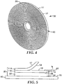
- adhesive surface 24 of PSA layer 26 contacts first major release surface 17 of first release layer 13 when adhesive tape assembly 20 is wound into a roll 32.
- Roll 32 exhibits a desired level of roll stability due to (1) the bond strength between adhesive surface 24 of PSA layer 26 and first release surface 17 of first release layer 13, (2) the bond strength between surface 19 of first backing layer 15 and surface 18 of second backing layer 14, and (3) the bond strength between second release surface 16 of second release layer 12 and adhesive surface 28 of PSA layer 30.
- Planetary rolls of a double-sided PSA tape assembly having two liners that are made with a tape having a thickness of at least 375 ⁇ m (15 mils) or more can be particularly prone to roll instability problems, because the rolls tend to be larger in diameter compared to tape assemblies with thinner tapes, in order to provide the same length of tape on a single roll.
- Such tape assemblies that are narrow in width can be even more likely to exhibit roll instability.
- the adhesive tape assemblies of the present invention are less likely to exhibit roll instability, even when comparable lengths of the tape assembly are relatively narrow in width and the adhesive tape has a thickness of at least 375 ⁇ m (15 mils) or more.
- the adhesive tape assembly 20 has an overall thickness, t , of 0.052 inches (0.132 cm) and is wound into a roll 32 having tape end 29, with adhesive surface 24 of PSA layer 26 in contact with first release surface 17 of first release layer 13, the roll can exhibit roll stability (i.e., the coils forming the roll 32 do not substantially telescope or fall apart when the roll 32 is held suspended along its outer circumferential edge) even when the roll 32 has a diameter d that is at least 20 times the width w of the adhesive tape assembly 20.
- roll stability i.e., the coils forming the roll 32 do not substantially telescope or fall apart when the roll 32 is held suspended along its outer circumferential edge
- This is the minimum diameter to width ratio at which roll stability problems have been experienced with rolls of prior adhesive tape assemblies comprising a double-sided adhesive tape, with a first PSA side and a second PSA side, and a release liner releasably bonded to each PSA side.
- An example of an adhesive tape assembly 20 that can be used to form a narrow roll 32 according to the present invention has a width w of up to 1 inch (2.54 cm), a thickness of 0.052 inches (0.132 cm) and a length in the range of from 36 yards (33 m) to 144 yards (132 m) and, it is believed, even longer (i.e., a diameter to width ratio ranging from 20 to 70).
- the present adhesive tape assemblies will have a width w of up to 0.5 inches (1.27 cm), a thickness of 0.052 inches (0.132 cm) and a length in the range of from 36 yards (33 m) to 144 yards (132 m) and, it is believed, even longer (i.e., a diameter to width ratio ranging from about 20 to 70).
- an optional tab may be attached to a back side surface (e.g., back side surface 18, 19, or both 18 and 19) of at least one of backing layers 14 and 15 to facilitate separation of a portion of the delaminatable liner (e.g., delaminatable portions 11B) from adhesive tape 22 and/or separation of a portion of the delaminatable liner (e.g., delaminatable portions 11A) from another portion of the delaminatable liner (e.g., delaminatable portions 11B).
- An exemplary embodiment using a tab is shown in Fig. 5 .
- exemplary adhesive tape assembly 20 is attached to substrate 50 such that front adhesive surface 24 is permanently adhered to surface 51 of substrate 50.
- Delaminatable portion 11A is shown in a partially removed position so that first and second back side surfaces 19 and 18 of delaminatable portion 11A and delaminatable portion 11B are exposed. (Although not shown in Fig.
- a second tab may be attached to first back side surface 19 of delaminatable portion 11 A prior to or during formation of delaminatable liner 11 and be used to separate delaminatable portion 11A from delaminatable portion 11B so as to put delaminatable portion 11A in the partially removed position as shown.
- tab 40 is attached to second back side surface 18 of delaminatable portion 11B.
- tab 40 is heat-bonded to a given back side surface. Once attached, tab 40 can be used to facilitate removal of delaminatable portion 11B from back adhesive surface 28 of adhesive tape 22.
- second major release surface 16 of delaminatable portion 11B is formulated so that removal of delaminatable portion 11B does not cause significant damage to double-sided adhesive tape 22 (i.e., does not cause cohesive failure, substantial tearing or substantial permanent stretching of the tape).
- Tab 40 can comprise at least one of a polyamide, polypropylene, polyethylene, ethylene vinyl acetate, polyester, thermoplastic polyolefin (TPO), copolymer of polyethylene and polypropylene, and combinations thereof.
- Tab 40 is operatively adapted (e.g., dimensioned and formulated) for being heat bonded to second back side surface 18 of second back side layer 14 (or first back side surface 19 of first back side layer 15) so as to allow delaminatable portion 11B (or delaminatable portion 11A) of delaminatable release liner 11 to be removed from adhesive tape 22 by pulling on the tab 40 in the direction shown by the arrow in Fig. 5 .
- Such a tab 40 is intended to make it easier for delaminatable portion 11B (or delaminatable portion 11 A) of delaminatable release liner 11 to be removed.
- Suitable materials for tab 40 intended to be heat bonded to a PE, PP, TPO or PE/PP second back side layer 14 (or first back side layer 15), can include polyamides, PEs, PPs, TPOs, EVAs, and PE/PPs.
- Suitable materials for tab 40 intended to be heat bonded to a PP second back side layer 14 (or first back side layer 15) can include polyamides, TPOs, PPs, and PE/PPs.
- Suitable materials for tab 40 to be heat bonded to a polyester second back side layer 14 (or first back side layer 15) can include polyesters, copolyesters, polyamides and polyimides.
- a tab may also be formed from a tape having a backing coated with a suitable pressure-sensitive adhesive, wherein the pressure-sensitive adhesive has a sufficient bond strength to the layer of material to be removed so that when the tab is applied to the surface of the layer and pulled, the appropriate layer separates from the tape assembly.
- Suitable backing materials have a tensile strength greater than the bond strength needed to remove the layer. Examples of suitable materials include polyesters, polypropylene, biaxially oriented polypropylene, paper, polyamides, and the like.
- Pressure-sensitive adhesives can be selected to bond well to the layer to be removed. Suitable adhesives include acrylic adhesives, tackified block copolymer adhesives, silicone adhesives, and the like.
- the adhesive tape assemblies of the present invention can be formed by a variety of conventional process steps.
- backing layers 14 and 15 may be co-extruding to form separatable portion of the delaminatable release liner.
- backing layers 14 and 15 can be formed by extruding one of the layers (e.g., first backing layer 15) onto the other layer (e.g., second backing layer 14) or vice versa.
- conventional commercially available extruders and techniques well known in the art can be used.
- conventional blown film extrusion equipment and techniques can be used to simultaneously co-extrude two or more layers (e.g., layers 14 and 15). Extruders force their corresponding layers through a common die.
- the various layers can be laminated together simultaneously as they are formed.
- the laminated layers are extruded into the form of a tube.
- the tube is then collapsed, rolled flat and the edges trimmed to form backing layers 14 and 15.
- Backing layers 14 and 15 are then optionally coated with a release layer as described above, and then subsequently laminated to a double sided adhesive tape 22 to form a tape assembly 20.
- the release material includes silicone or fluorocarbon
- the release material may be applied as a solvent based coating, a water based coating, or a 100% solids coating (i.e., the solids are in liquid form without a solvent) onto backing layers 14 and 15.
- a method of using an adhesive tape assembly comprises applying a double-sided pressure sensitive adhesive tape to one or more surfaces, wherein the method comprises (1) providing an adhesive tape assembly, wherein the adhesive tape assembly comprises a double-sided adhesive tape comprising front and back adhesive sides, each of the adhesive sides comprising a pressure sensitive adhesive; and a delaminatable release liner in contact with, bonded to and readily removable from the back adhesive side of the double-sided adhesive tape, the delaminatable release liner comprising a first major release surface on one side of the release liner, a second major release surface on an opposite side of the release liner, and a plane of weakness between the first and second major release surfaces, wherein the release liner can be readily delaminated lengthwise along the plane of weakness, between the first and second major release surfaces, so as to form a first delaminated layer and a second delaminated layer, with the first delaminated layer comprising the first major release
- the adhesive tape assembly may be in roll form (see Fig. 2 ).
- the above exemplary method further comprises unwinding the roll to expose the front adhesive side of the adhesive tape.
- the above exemplary method may further comprise one or more processing steps once the first delaminated layer (e.g., delaminatable portion 11A) is removed from the second back side surface of the second delaminated layer (e.g., delaminatable portion 11B), and a tab is attached to the second delaminated layer (e.g., delaminatable portion 11B).
- the method may further comprise the step of applying paint onto the first substrate and the second back side surface of the second delaminated layer.
- the method may further comprise the step of pulling the tab to remove the second delaminated layer (e.g., delaminatable portion 11B) from the adhesive tape assembly to expose the pressure sensitive adhesive of the back adhesive side.
- the exposed pressure sensitive adhesive of the back adhesive side may be brought into contact with a second substrate so that the adhesive tape is positioned between the first substrate and the second substrate.
- the first substrate comprises an elastomeric article
- the second substrate comprises a painted or unpainted surface of a vehicle.
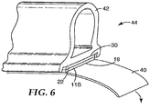
- an article assembly 44 of the present invention includes adhesive tape 22 bonded via front adhesive side 24 to, for example, a plastic or elastomeric article 42 (e.g., an automotive exterior trim part, such as body side moldings and claddings used on the sides of automobile bodies, and the like; a weatherstrip for sealing automobile doors and windows, and the like; as well as other plastic and elastomeric containing articles), with delaminatable portion 11B (e.g., second release layer 12 and second backing layer 14) being releasably bonded to back adhesive side 28 of tape 22.
- a tab 40 is bonded to back side surface 18 of second backing layer 14.
- back side surface 18 of second backing layer 14 be substantially free of a release material such as, for example, silicone that can prevent or at least significantly inhibit the bonding of tab 40 to back side surface 18 of second backing layer 14.
- the bond between tab 40 and second backing layer 14 should be strong enough to allow delaminatable portion 11B of delaminatable release liner 11 to be removed from adhesive tape 22 by pulling on tab 40 in the direction shown by the arrow in Fig. 6 .
- the back side (i.e., back side surface 19) of first backing layer 15 can also be preferable for the back side (i.e., back side surface 19) of first backing layer 15 to be similarly free of such a release material, especially if a tab 40 is intended to be bonded to back side surface 19 of first backing layer 15.
- Such a use of a tab 40 i.e., bonded to back side surface 19 and/or 18 can enable the corresponding delaminatable portion (i.e., delaminatable portion 11A and/or 11B, respectively) to be more easily removed.
- Fig. 6 shows article 42 after delaminatable portion 11A of delaminatable release liner 11 has been removed from delaminatable portion 11B and separated from adhesive side 24 of adhesive tape 22.
- roll 32 can be unwound such that back side 28 of adhesive tape 22 is exposed (i.e., first release surface 17 of first release layer 13 is still in contact with front adhesive surface 24 of PSA layer 26 after unwounding roll 32).
- delaminatable portion 11B of delaminatable release liner 11 can be removed first after bonding back side 28 of adhesive tape 22 to article 42. With such an application, it may be desirable to bond a tab 40 to back side surface 19 of first backing layer 15 to assist in the removal of delaminatable portion 11 A from adhesive tape 22 as described above.
- a one inch (2.5 cm) wide by 6 inch (15 cm) long sample is cut from a sample adhesive tape assembly or from a piece of the liner.
- the test is performed at a 90 degree angle using an Instron tensile tester with a jaw separation speed of 30.48 cm (12 inches) per minute.
- second layer 16 is laminated to an anodized aluminum panel having a thickness of 0.127 mm using an acrylic pressure-sensitive adhesive tape and rolled down with a 6.8 kg metal roller.
- the first backing layer 15 is separated from second backing layer 14 manually (i.e., with a fingernail or razor blade) to start the delamination.
- Approximately 2.5 cm of the first backing layer is delaminated.
- the delaminated portion of the backing is placed in the upper jaw of the tensile tester and the panel is positioned horizontally in a fixture on the lower jaw. The average peel force for five test samples is recorded.
- Sample Preparation for Tape A strip of tape is adhered to a 0.127 mm thick anodized aluminum panel and rolled down with a 6.8 kg roller. After allowing the test tape to dwell in contact with the liner for 72 hours at room temperature, the panel is positioned in the tensile tester as described above with all of the layers of the release liner clamped together in the upper jaw. Linear release was measured as an average peel force using an integrated average over 5 seconds test time.
- thermoplastic olefin (TPO) film was prepared by coextruding three layers of TPO (FLEXATHENETM TP38NC01X01 thermoplastic polyolefin available from Equistar Chemicals, LP, Houston, TX) on a blown film extruder.
- the film had a total thickness of 5 mils (0.127 mm) with the middle layer containing a red pigment while the outer layers were essentially clear.
- Each of the layers was 37.5 ⁇ m (1.5 mils)
- LDPE low density polyethylene
- the blown films were converted into flat films and laminated to each other by extruding 0.5 mil (0.012 mm) LDPE (PETROTHENETM 951 low density polyethylene) onto the 125 ⁇ m (5 mils) TPO film and laminating the 25 ⁇ m (1 mil) LDPE film to it using a nip roll. During extrusion, the molten LDPE fuses to the LDPE film while adhering delaminatably to the TPO film.
- the resulting laminate is a suitable delaminatable release liner for an acrylic pressure-sensitive adhesive tape such as Acrylic Foam Tape 4220 available from 3M Company, St. Paul MN.
- the release liner of Example 1 was corona treated to a surface energy of at least 30 dynes.
- a silicone coating prepared according to U.S. Patent No. 6,835,422 was coated onto the polyethylene surface of the release liner.
- the liner is a suitable release liner for a strippable tape.
- the silicone coated release liner of Example 2 was coated with a UV curable epoxy silicone release material.
- the composition contained 40 parts UV9430 epoxy silicone, 60 parts UV9315 epoxy silicone, and 2 parts of UV9380C Photocatalyst. All of the components are available from GE Silicones, Waterford, NY.
- a delaminatable release liner is prepared according to the method of Example 1.
- a 2.54 cm (1 inch) wide strip of 0.0.13 mm (0.5 mil) thick polymethylmethacrylate (PMMA) film is placed across the TPO film so that the LDPE extrudate and LDPE film are laminated over the PMMA strip.
- PMMA polymethylmethacrylate
- the film laminate is rolled into a stock roll with the PMMA film strip approximately 6.096 m (20 feet) into the roll.
- the stock roll is optionally coated on one or both sides with a release material (e.g., silicones of Examples 2 and 3) and then laminated to a double coated tape to form a tape stock roll.
- a release material e.g., silicones of Examples 2 and 3
- the tape stock roll is then slit into narrower, e.g., 1 cm, rolls of approximately 20 feet in length.
- narrower e.g. 1 cm
- the section of the PMMA strip on each roll forms a tab that may be used to start the delamination of the polyethylene release layer during further processing.
Landscapes
- Chemical & Material Sciences (AREA)
- Organic Chemistry (AREA)
- Engineering & Computer Science (AREA)
- Mechanical Engineering (AREA)
- Adhesive Tapes (AREA)
- Laminated Bodies (AREA)
- Adhesives Or Adhesive Processes (AREA)
Priority Applications (1)
| Application Number | Priority Date | Filing Date | Title |
|---|---|---|---|
| PL06839438T PL1963451T3 (pl) | 2005-12-23 | 2006-12-19 | Przekładka rozdzielająca do klejów przylepcowych i sposób jej użycia |
Applications Claiming Priority (2)
| Application Number | Priority Date | Filing Date | Title |
|---|---|---|---|
| US75399605P | 2005-12-23 | 2005-12-23 | |
| PCT/US2006/048494 WO2007075724A2 (en) | 2005-12-23 | 2006-12-19 | Release liner for pressure sensitive adhesives and method of use |
Publications (2)
| Publication Number | Publication Date |
|---|---|
| EP1963451A2 EP1963451A2 (en) | 2008-09-03 |
| EP1963451B1 true EP1963451B1 (en) | 2017-08-09 |
Family
ID=38218546
Family Applications (1)
| Application Number | Title | Priority Date | Filing Date |
|---|---|---|---|
| EP06839438.6A Active EP1963451B1 (en) | 2005-12-23 | 2006-12-19 | Release liner for pressure sensitive adhesives and method of use |
Country Status (10)
| Country | Link |
|---|---|
| US (2) | US9359530B2 (zh) |
| EP (1) | EP1963451B1 (zh) |
| JP (1) | JP5676081B2 (zh) |
| KR (1) | KR101401703B1 (zh) |
| CN (1) | CN101384682B (zh) |
| BR (1) | BRPI0620331B1 (zh) |
| CA (1) | CA2634736A1 (zh) |
| MX (1) | MX2008008245A (zh) |
| PL (1) | PL1963451T3 (zh) |
| WO (1) | WO2007075724A2 (zh) |
Families Citing this family (35)
| Publication number | Priority date | Publication date | Assignee | Title |
|---|---|---|---|---|
| ES2389660T3 (es) | 2004-12-16 | 2012-10-30 | Saint-Gobain Abrasives, Inc. | Vaso de suministro de líquido y unidad de bolsa para pistolas de pulverización |
| CA2634736A1 (en) * | 2005-12-23 | 2007-07-05 | 3M Innovative Properties Company | Release liner for pressure sensitive adhesives and method of use |
| US11040360B2 (en) | 2006-06-20 | 2021-06-22 | Saint-Gobain Abrasives, Inc. | Liquid supply assembly |
| US8033413B2 (en) | 2006-06-20 | 2011-10-11 | Saint-Gobain Abrastives, Inc. | Liquid supply assembly |
| US20100242541A1 (en) * | 2007-08-01 | 2010-09-30 | Kiyohara Kabushiki Kaisha | Ornamental rod-like body and method for producing the same |
| US10087343B2 (en) * | 2007-08-06 | 2018-10-02 | Immunolight, Llc | Adhesive bonding composition and method of use |
| DE102008021842A1 (de) | 2008-04-30 | 2009-11-05 | Tesa Se | Polyolefinfolie und Verwendung derselben |
| MY156064A (en) * | 2009-03-31 | 2016-01-15 | Avery Dennison Corp | Resealable laminate for heat sealed packaging |
| JP2010241967A (ja) * | 2009-04-07 | 2010-10-28 | Nitto Denko Corp | 再剥離性粘着シート及びこれを用いた被着体の加工方法 |
| WO2012154621A2 (en) | 2011-05-06 | 2012-11-15 | Saint-Gobain Abrasives, Inc. | Paint cup assembly with an extended ring |
| CN102250559B (zh) * | 2011-05-25 | 2013-10-23 | 北京航空航天大学 | 一种喷涂用遮蔽材料的制备方法 |
| EP2726214B1 (en) | 2011-06-30 | 2019-05-01 | Saint-Gobain Abrasives, Inc. | Paint cup assembly |
| JP5231670B1 (ja) * | 2011-10-20 | 2013-07-10 | 株式会社フジクラ | ディスプレイ装置用加飾フィルム及び保護パネル |
| CA2862420C (en) | 2011-12-30 | 2018-08-07 | Saint-Gobain Abrasives, Inc. | Convertible paint cup assembly with air inlet valve |
| US20140190616A1 (en) * | 2013-01-09 | 2014-07-10 | ST Global Partners, LLC | Double-sided adhesive membrane for finish material installation |
| FR3005661B1 (fr) * | 2013-05-16 | 2016-06-10 | Novacel Sa | Film adhesif sensible a la pression et son utilisation pour la protection de surfaces |
| CN104228246A (zh) | 2013-06-13 | 2014-12-24 | 美国圣戈班性能塑料公司 | 基于聚氨酯分散液的泡棉密封垫片和粘合胶带 |
| US20150030794A1 (en) * | 2013-07-24 | 2015-01-29 | GM Global Technology Operations LLC | Adhesive tape release liner |
| WO2015021294A1 (en) * | 2013-08-07 | 2015-02-12 | 3M Innovative Properties Company | Wardrobe tape and method of using same |
| CN104512076B (zh) * | 2013-09-26 | 2018-05-22 | 美国圣戈班性能塑料公司 | 超薄泡棉垫片和粘合胶带 |
| JP2015147847A (ja) * | 2014-02-05 | 2015-08-20 | 日東電工株式会社 | 表面保護シート用基材および表面保護シート |
| ES2948676T3 (es) | 2014-03-18 | 2023-09-15 | Immunolight Llc | Composición de unión adhesiva mejorada y método de uso |
| KR20170042651A (ko) * | 2014-08-18 | 2017-04-19 | 애버리 데니슨 코포레이션 | 접착 테이프 및 히트 스프레더 어셈블리 |
| US20170348947A1 (en) * | 2014-12-19 | 2017-12-07 | Dsm Ip Assets B.V. | Ultrahigh molecular weight polyethylene adhesive tapes |
| EP3404059B1 (en) * | 2016-01-14 | 2023-03-01 | Nitto Denko Corporation | Method for manufacturing surface-modified thermoplastic resin |
| US10835069B2 (en) | 2016-05-09 | 2020-11-17 | Optimum Technologies, Inc. | Reinforced rug tab, reinforced rug tab kit, and method of using the same |
| US10292518B1 (en) | 2016-05-09 | 2019-05-21 | Optimum Technologies, Inc. | Rug tab, rug tab kit, and method of using the same |
| US10967605B2 (en) * | 2017-03-17 | 2021-04-06 | The Boeing Company | Decorative laminates having an open-cell foam layer |
| US10046551B1 (en) * | 2017-07-05 | 2018-08-14 | Sian-De Wei | Recycling method for detaching the cloth material from the E.V.A. insole residual product |
| JP7240806B2 (ja) * | 2017-10-06 | 2023-03-16 | 日東電工株式会社 | 剥離フィルム付き粘着シート |
| DE102018211824A1 (de) * | 2018-07-17 | 2020-01-23 | Tesa Se | Releaseliner mit partieller Silikonbeschichtung |
| DE102018216112A1 (de) * | 2018-09-21 | 2020-03-26 | Tesa Se | Klebeband mit geformter Abziehlasche und Verfahren zur Herstellung eines solchen Klebebandes |
| MX2021006811A (es) * | 2018-12-11 | 2021-07-02 | Gcp Applied Tech Inc | Membrana previamente aplicada con capa anti-sumergible. |
| JP7431321B2 (ja) * | 2020-05-01 | 2024-02-14 | 株式会社寺岡製作所 | 粘着テープ |
| US20240208763A1 (en) | 2021-04-08 | 2024-06-27 | 3M Innovative Properties Company | Surface Characterization Module and System Including Same |
Family Cites Families (42)
| Publication number | Priority date | Publication date | Assignee | Title |
|---|---|---|---|---|
| US2816655A (en) | 1954-02-15 | 1957-12-17 | Shawinigan Resins Corp | Low adhesion coatings on adhesive tapes and liners |
| US2862613A (en) | 1955-10-20 | 1958-12-02 | Norton Co | Pressure-sensitive adhesive tapes |
| US4274661A (en) * | 1971-06-23 | 1981-06-23 | Monarch Marking Systems, Inc. | Composite web of pressure sensitive labels |
| JPS5245763U (zh) * | 1975-09-27 | 1977-03-31 | ||
| JPS5245763A (en) | 1975-10-09 | 1977-04-11 | Nobuo Koyama | Sludgelike waste drier |
| US4287255A (en) | 1979-09-06 | 1981-09-01 | Avery International Corporation | Reinforced adhesive tapes |
| DE3173098D1 (en) * | 1980-05-03 | 1986-01-16 | Raychem Ltd | Device and method for enclosing objects |
| CA1175330A (en) | 1982-09-01 | 1984-10-02 | David Bray | Method of manufacturing adhesive tape |
| US4778703A (en) | 1987-04-02 | 1988-10-18 | Compac Corporation | Adhesive tape for insulation application |
| US4822451A (en) | 1988-04-27 | 1989-04-18 | Minnesota Mining And Manufacturing Company | Process for the surface modification of semicrystalline polymers |
| US5167995A (en) | 1990-06-08 | 1992-12-01 | Minnesota Mining And Manufacturing Company | Low temperature shock resistant release liner |
| DE69124114T2 (de) | 1991-03-28 | 1997-07-24 | Leiras Oy, Turku | Verfahren zum herstellen von subkutanen kapseln |
| US5178924A (en) | 1991-06-17 | 1993-01-12 | Minnesota Mining And Manufacturing Company | Release liner |
| JPH0680846A (ja) | 1991-11-22 | 1994-03-22 | Taoka Chem Co Ltd | エチレン−酢酸ビニル共重合体系組成物及びそれを用いるロール加工法 |
| AU667766B2 (en) * | 1993-05-27 | 1996-04-04 | Paul Hartmann Ag | Hydrogel wound dressing product |
| US5491013A (en) | 1994-08-31 | 1996-02-13 | Rexam Industries Corp. | Static-dissipating adhesive tape |
| US5525375A (en) | 1995-06-05 | 1996-06-11 | Moore Business Forms, Inc. | Process for producing hot melt release coating |
| US5932352A (en) | 1995-11-21 | 1999-08-03 | Higgins; David Edward | Release film |
| NO306205B1 (no) | 1996-01-11 | 1999-10-04 | Borealis As | Plastpall |
| NL1004127C2 (nl) | 1996-09-27 | 1998-03-31 | Johannes Antonius Maria Reinde | Prelaminaat. |
| NL1007603C2 (nl) | 1997-11-24 | 1999-05-26 | Johannes Wilhelmus Gerar Hooft | Bevestigingsmiddel. |
| JP4117935B2 (ja) | 1998-01-30 | 2008-07-16 | スリーエム カンパニー | 剥離ライナ及びそれを有する両面粘着テープ |
| US6365254B1 (en) | 1998-02-02 | 2002-04-02 | 3M Innovative Properties Company | Roll stabilizing release liner |
| US6632311B1 (en) | 1998-06-23 | 2003-10-14 | 3M Innovative Properties Company | Tape roll tab application method and article |
| US6103152A (en) | 1998-07-31 | 2000-08-15 | 3M Innovative Properties Co. | Articles that include a polymer foam and method for preparing same |
| US6451398B1 (en) * | 1998-11-24 | 2002-09-17 | Michael S. Sylvester | Double-sided self-adhesive reinforced foam tape |
| JP2001003010A (ja) * | 1999-06-16 | 2001-01-09 | Nitto Denko Corp | 感圧性両面接着シート及び感圧性接着部材 |
| US6521309B1 (en) * | 1999-11-11 | 2003-02-18 | Tyco Adhesives Lp | Double-sided single-liner pressure-sensitive adhesive tape |
| US6258427B1 (en) | 1999-12-29 | 2001-07-10 | Kimberly-Clark Worldwide, Inc. | Flushable double-sided release liner |
| US6630531B1 (en) | 2000-02-02 | 2003-10-07 | 3M Innovative Properties Company | Adhesive for bonding to low surface energy surfaces |
| US20030211308A1 (en) | 2001-02-02 | 2003-11-13 | Khandpur Ashish K | Adhesive for bonding to low surface energy surfaces |
| JP2001240825A (ja) | 2000-02-25 | 2001-09-04 | Oji Tac Hanbai Kk | 貼替防止用粘着テープ |
| US6469372B2 (en) | 2000-05-16 | 2002-10-22 | Texas Instruments Incorporated | Matched thermal expansion carrier tape assemblage for semiconductor devices |
| US6951676B2 (en) * | 2000-09-25 | 2005-10-04 | 3M Innovative Properties Company | Butt splicing tapes and butt splicing methods |
| US6780484B2 (en) | 2001-02-02 | 2004-08-24 | 3M Innovative Properties Company | Adhesive article and method of preparing |
| US6756101B2 (en) * | 2001-07-16 | 2004-06-29 | Specialty Tapes, Division Of Rsw | Tape for use with high-speed webs and method of use thereof |
| US20030010422A1 (en) * | 2001-07-16 | 2003-01-16 | John Starkey | High-speed web-splicing tape and method of use thereof |
| JP3754660B2 (ja) | 2002-06-11 | 2006-03-15 | 株式会社カトー精工 | 離型用タブ付き両面粘着シート積層体とその製造方法 |
| US20070221327A1 (en) | 2004-04-30 | 2007-09-27 | Zoller Panu K | Roll Stabilized Double-Sided Pressure Sensitive Adhesive Tape Assembly |
| DE102005057932A1 (de) * | 2005-12-02 | 2007-06-06 | Tesa Ag | Rolle einer Etikettenbahn in Form einer archimedischen Spirale aus hintereinander angeordneten Etiketten |
| CA2634736A1 (en) * | 2005-12-23 | 2007-07-05 | 3M Innovative Properties Company | Release liner for pressure sensitive adhesives and method of use |
| JP6337100B2 (ja) * | 2013-11-05 | 2018-06-06 | シカゴ タグ アンド ラベル インコーポレイテッドChicago Tag & Label, Inc. | ラベルフォーム |
-
2006
- 2006-12-19 CA CA002634736A patent/CA2634736A1/en not_active Abandoned
- 2006-12-19 WO PCT/US2006/048494 patent/WO2007075724A2/en active Application Filing
- 2006-12-19 PL PL06839438T patent/PL1963451T3/pl unknown
- 2006-12-19 BR BRPI0620331-0A patent/BRPI0620331B1/pt not_active IP Right Cessation
- 2006-12-19 MX MX2008008245A patent/MX2008008245A/es active IP Right Grant
- 2006-12-19 EP EP06839438.6A patent/EP1963451B1/en active Active
- 2006-12-19 CN CN2006800516269A patent/CN101384682B/zh not_active Expired - Fee Related
- 2006-12-19 JP JP2008547456A patent/JP5676081B2/ja not_active Expired - Fee Related
- 2006-12-19 US US12/158,187 patent/US9359530B2/en active Active
- 2006-12-19 KR KR1020087015185A patent/KR101401703B1/ko active IP Right Grant
-
2016
- 2016-05-23 US US15/161,335 patent/US10081133B2/en active Active
Also Published As
| Publication number | Publication date |
|---|---|
| MX2008008245A (es) | 2009-03-04 |
| EP1963451A2 (en) | 2008-09-03 |
| JP2009521563A (ja) | 2009-06-04 |
| US10081133B2 (en) | 2018-09-25 |
| CA2634736A1 (en) | 2007-07-05 |
| WO2007075724A3 (en) | 2008-08-07 |
| PL1963451T3 (pl) | 2017-12-29 |
| KR20080078849A (ko) | 2008-08-28 |
| US20160264824A1 (en) | 2016-09-15 |
| US20090145542A1 (en) | 2009-06-11 |
| KR101401703B1 (ko) | 2014-05-30 |
| CN101384682A (zh) | 2009-03-11 |
| BRPI0620331A2 (pt) | 2011-11-08 |
| CN101384682B (zh) | 2013-01-02 |
| BRPI0620331B1 (pt) | 2018-02-14 |
| WO2007075724A2 (en) | 2007-07-05 |
| JP5676081B2 (ja) | 2015-02-25 |
| US9359530B2 (en) | 2016-06-07 |
Similar Documents
| Publication | Publication Date | Title |
|---|---|---|
| US10081133B2 (en) | Release liner for pressure sensitive adhesives and method of use | |
| KR101495972B1 (ko) | 롤 안정화 양면 감압성 접착 테이프 조립체 | |
| KR0181504B1 (ko) | 저온 쇼크 내성 박리 라이너 | |
| AU685159B2 (en) | Removable foam adhesive tape | |
| JP5525443B2 (ja) | 折り畳み可能なプルタブを備える取り外し可能な接着テープ | |
| JP5323067B2 (ja) | 取り外し可能な接着テープ及びプルタブフィルム、並びにキット | |
| KR20110013435A (ko) | 폴리올레핀 이형 필름, 및 이의 용도 | |
| JP2010531917A (ja) | 取り外し可能な接着テープ及びプルタブ、並びに形成方法 | |
| EP3160747B1 (en) | Film laminated, water activated paper tape and methods of making same | |
| EP3060390B1 (en) | Label assembly and method of dispensing low-stiffness labels | |
| JP4703069B2 (ja) | 剥離ライナー、及び感圧性両面接着テープ又はシート | |
| JP2003147295A (ja) | 粘着部材及びその製造方法 | |
| JP4003099B2 (ja) | 自動車塗膜保護用粘着フィルム | |
| KR20070020473A (ko) | 롤 안정화 양면 감압성 접착 테이프 조립체 | |
| JPS60188487A (ja) | 粘着テ−プ | |
| WO2021003320A1 (en) | Tape | |
| MXPA98001047A (en) | Removable adhesive tape with sequential control control |
Legal Events
| Date | Code | Title | Description |
|---|---|---|---|
| PUAI | Public reference made under article 153(3) epc to a published international application that has entered the european phase |
Free format text: ORIGINAL CODE: 0009012 |
|
| 17P | Request for examination filed |
Effective date: 20080627 |
|
| AK | Designated contracting states |
Kind code of ref document: A2 Designated state(s): AT BE BG CH CY CZ DE DK EE ES FI FR GB GR HU IE IS IT LI LT LU LV MC NL PL PT RO SE SI SK TR |
|
| AX | Request for extension of the european patent |
Extension state: AL BA HR MK RS |
|
| R17D | Deferred search report published (corrected) |
Effective date: 20080807 |
|
| RIC1 | Information provided on ipc code assigned before grant |
Ipc: C09J 7/02 20060101AFI20080910BHEP |
|
| DAX | Request for extension of the european patent (deleted) | ||
| 17Q | First examination report despatched |
Effective date: 20140708 |
|
| REG | Reference to a national code |
Ref country code: DE Ref legal event code: R079 Ref document number: 602006053310 Country of ref document: DE Free format text: PREVIOUS MAIN CLASS: C09J0007000000 Ipc: C09J0007020000 |
|
| GRAP | Despatch of communication of intention to grant a patent |
Free format text: ORIGINAL CODE: EPIDOSNIGR1 |
|
| STAA | Information on the status of an ep patent application or granted ep patent |
Free format text: STATUS: GRANT OF PATENT IS INTENDED |
|
| RIC1 | Information provided on ipc code assigned before grant |
Ipc: B29K 63/00 20060101ALI20161129BHEP Ipc: B29L 31/30 20060101ALI20161129BHEP Ipc: B29L 9/00 20060101ALI20161129BHEP Ipc: B29C 65/50 20060101ALI20161129BHEP Ipc: C09J 7/02 20060101AFI20161129BHEP |
|
| INTG | Intention to grant announced |
Effective date: 20170103 |
|
| GRAS | Grant fee paid |
Free format text: ORIGINAL CODE: EPIDOSNIGR3 |
|
| GRAA | (expected) grant |
Free format text: ORIGINAL CODE: 0009210 |
|
| STAA | Information on the status of an ep patent application or granted ep patent |
Free format text: STATUS: THE PATENT HAS BEEN GRANTED |
|
| AK | Designated contracting states |
Kind code of ref document: B1 Designated state(s): AT BE BG CH CY CZ DE DK EE ES FI FR GB GR HU IE IS IT LI LT LU LV MC NL PL PT RO SE SI SK TR |
|
| REG | Reference to a national code |
Ref country code: GB Ref legal event code: FG4D |
|
| REG | Reference to a national code |
Ref country code: CH Ref legal event code: EP Ref country code: AT Ref legal event code: REF Ref document number: 916812 Country of ref document: AT Kind code of ref document: T Effective date: 20170815 |
|
| REG | Reference to a national code |
Ref country code: IE Ref legal event code: FG4D |
|
| REG | Reference to a national code |
Ref country code: DE Ref legal event code: R096 Ref document number: 602006053310 Country of ref document: DE |
|
| REG | Reference to a national code |
Ref country code: FR Ref legal event code: PLFP Year of fee payment: 12 |
|
| REG | Reference to a national code |
Ref country code: DE Ref legal event code: R079 Ref document number: 602006053310 Country of ref document: DE Free format text: PREVIOUS MAIN CLASS: C09J0007020000 Ipc: C09J0007200000 |
|
| REG | Reference to a national code |
Ref country code: NL Ref legal event code: MP Effective date: 20170809 |
|
| REG | Reference to a national code |
Ref country code: LT Ref legal event code: MG4D |
|
| REG | Reference to a national code |
Ref country code: AT Ref legal event code: MK05 Ref document number: 916812 Country of ref document: AT Kind code of ref document: T Effective date: 20170809 |
|
| PG25 | Lapsed in a contracting state [announced via postgrant information from national office to epo] |
Ref country code: AT Free format text: LAPSE BECAUSE OF FAILURE TO SUBMIT A TRANSLATION OF THE DESCRIPTION OR TO PAY THE FEE WITHIN THE PRESCRIBED TIME-LIMIT Effective date: 20170809 Ref country code: FI Free format text: LAPSE BECAUSE OF FAILURE TO SUBMIT A TRANSLATION OF THE DESCRIPTION OR TO PAY THE FEE WITHIN THE PRESCRIBED TIME-LIMIT Effective date: 20170809 Ref country code: SE Free format text: LAPSE BECAUSE OF FAILURE TO SUBMIT A TRANSLATION OF THE DESCRIPTION OR TO PAY THE FEE WITHIN THE PRESCRIBED TIME-LIMIT Effective date: 20170809 Ref country code: LT Free format text: LAPSE BECAUSE OF FAILURE TO SUBMIT A TRANSLATION OF THE DESCRIPTION OR TO PAY THE FEE WITHIN THE PRESCRIBED TIME-LIMIT Effective date: 20170809 Ref country code: NL Free format text: LAPSE BECAUSE OF FAILURE TO SUBMIT A TRANSLATION OF THE DESCRIPTION OR TO PAY THE FEE WITHIN THE PRESCRIBED TIME-LIMIT Effective date: 20170809 |
|
| PG25 | Lapsed in a contracting state [announced via postgrant information from national office to epo] |
Ref country code: GR Free format text: LAPSE BECAUSE OF FAILURE TO SUBMIT A TRANSLATION OF THE DESCRIPTION OR TO PAY THE FEE WITHIN THE PRESCRIBED TIME-LIMIT Effective date: 20171110 Ref country code: LV Free format text: LAPSE BECAUSE OF FAILURE TO SUBMIT A TRANSLATION OF THE DESCRIPTION OR TO PAY THE FEE WITHIN THE PRESCRIBED TIME-LIMIT Effective date: 20170809 Ref country code: ES Free format text: LAPSE BECAUSE OF FAILURE TO SUBMIT A TRANSLATION OF THE DESCRIPTION OR TO PAY THE FEE WITHIN THE PRESCRIBED TIME-LIMIT Effective date: 20170809 Ref country code: IS Free format text: LAPSE BECAUSE OF FAILURE TO SUBMIT A TRANSLATION OF THE DESCRIPTION OR TO PAY THE FEE WITHIN THE PRESCRIBED TIME-LIMIT Effective date: 20171209 Ref country code: BG Free format text: LAPSE BECAUSE OF FAILURE TO SUBMIT A TRANSLATION OF THE DESCRIPTION OR TO PAY THE FEE WITHIN THE PRESCRIBED TIME-LIMIT Effective date: 20171109 |
|
| PGFP | Annual fee paid to national office [announced via postgrant information from national office to epo] |
Ref country code: PL Payment date: 20171006 Year of fee payment: 12 |
|
| PG25 | Lapsed in a contracting state [announced via postgrant information from national office to epo] |
Ref country code: RO Free format text: LAPSE BECAUSE OF FAILURE TO SUBMIT A TRANSLATION OF THE DESCRIPTION OR TO PAY THE FEE WITHIN THE PRESCRIBED TIME-LIMIT Effective date: 20170809 Ref country code: CZ Free format text: LAPSE BECAUSE OF FAILURE TO SUBMIT A TRANSLATION OF THE DESCRIPTION OR TO PAY THE FEE WITHIN THE PRESCRIBED TIME-LIMIT Effective date: 20170809 Ref country code: DK Free format text: LAPSE BECAUSE OF FAILURE TO SUBMIT A TRANSLATION OF THE DESCRIPTION OR TO PAY THE FEE WITHIN THE PRESCRIBED TIME-LIMIT Effective date: 20170809 |
|
| REG | Reference to a national code |
Ref country code: DE Ref legal event code: R097 Ref document number: 602006053310 Country of ref document: DE |
|
| PG25 | Lapsed in a contracting state [announced via postgrant information from national office to epo] |
Ref country code: IT Free format text: LAPSE BECAUSE OF FAILURE TO SUBMIT A TRANSLATION OF THE DESCRIPTION OR TO PAY THE FEE WITHIN THE PRESCRIBED TIME-LIMIT Effective date: 20170809 Ref country code: SK Free format text: LAPSE BECAUSE OF FAILURE TO SUBMIT A TRANSLATION OF THE DESCRIPTION OR TO PAY THE FEE WITHIN THE PRESCRIBED TIME-LIMIT Effective date: 20170809 Ref country code: EE Free format text: LAPSE BECAUSE OF FAILURE TO SUBMIT A TRANSLATION OF THE DESCRIPTION OR TO PAY THE FEE WITHIN THE PRESCRIBED TIME-LIMIT Effective date: 20170809 |
|
| PLBE | No opposition filed within time limit |
Free format text: ORIGINAL CODE: 0009261 |
|
| STAA | Information on the status of an ep patent application or granted ep patent |
Free format text: STATUS: NO OPPOSITION FILED WITHIN TIME LIMIT |
|
| 26N | No opposition filed |
Effective date: 20180511 |
|
| REG | Reference to a national code |
Ref country code: CH Ref legal event code: PL |
|
| GBPC | Gb: european patent ceased through non-payment of renewal fee |
Effective date: 20171219 |
|
| PG25 | Lapsed in a contracting state [announced via postgrant information from national office to epo] |
Ref country code: SI Free format text: LAPSE BECAUSE OF FAILURE TO SUBMIT A TRANSLATION OF THE DESCRIPTION OR TO PAY THE FEE WITHIN THE PRESCRIBED TIME-LIMIT Effective date: 20170809 |
|
| REG | Reference to a national code |
Ref country code: IE Ref legal event code: MM4A |
|
| PG25 | Lapsed in a contracting state [announced via postgrant information from national office to epo] |
Ref country code: LU Free format text: LAPSE BECAUSE OF NON-PAYMENT OF DUE FEES Effective date: 20171219 |
|
| REG | Reference to a national code |
Ref country code: BE Ref legal event code: MM Effective date: 20171231 |
|
| PG25 | Lapsed in a contracting state [announced via postgrant information from national office to epo] |
Ref country code: IE Free format text: LAPSE BECAUSE OF NON-PAYMENT OF DUE FEES Effective date: 20171219 |
|
| PG25 | Lapsed in a contracting state [announced via postgrant information from national office to epo] |
Ref country code: LI Free format text: LAPSE BECAUSE OF NON-PAYMENT OF DUE FEES Effective date: 20171231 Ref country code: BE Free format text: LAPSE BECAUSE OF NON-PAYMENT OF DUE FEES Effective date: 20171231 Ref country code: GB Free format text: LAPSE BECAUSE OF NON-PAYMENT OF DUE FEES Effective date: 20171219 Ref country code: CH Free format text: LAPSE BECAUSE OF NON-PAYMENT OF DUE FEES Effective date: 20171231 |
|
| PGFP | Annual fee paid to national office [announced via postgrant information from national office to epo] |
Ref country code: FR Payment date: 20181121 Year of fee payment: 13 |
|
| PG25 | Lapsed in a contracting state [announced via postgrant information from national office to epo] |
Ref country code: MC Free format text: LAPSE BECAUSE OF FAILURE TO SUBMIT A TRANSLATION OF THE DESCRIPTION OR TO PAY THE FEE WITHIN THE PRESCRIBED TIME-LIMIT Effective date: 20170809 Ref country code: HU Free format text: LAPSE BECAUSE OF FAILURE TO SUBMIT A TRANSLATION OF THE DESCRIPTION OR TO PAY THE FEE WITHIN THE PRESCRIBED TIME-LIMIT; INVALID AB INITIO Effective date: 20061219 |
|
| PG25 | Lapsed in a contracting state [announced via postgrant information from national office to epo] |
Ref country code: CY Free format text: LAPSE BECAUSE OF NON-PAYMENT OF DUE FEES Effective date: 20170809 |
|
| PG25 | Lapsed in a contracting state [announced via postgrant information from national office to epo] |
Ref country code: TR Free format text: LAPSE BECAUSE OF FAILURE TO SUBMIT A TRANSLATION OF THE DESCRIPTION OR TO PAY THE FEE WITHIN THE PRESCRIBED TIME-LIMIT Effective date: 20170809 |
|
| PG25 | Lapsed in a contracting state [announced via postgrant information from national office to epo] |
Ref country code: PT Free format text: LAPSE BECAUSE OF FAILURE TO SUBMIT A TRANSLATION OF THE DESCRIPTION OR TO PAY THE FEE WITHIN THE PRESCRIBED TIME-LIMIT Effective date: 20170809 |
|
| PG25 | Lapsed in a contracting state [announced via postgrant information from national office to epo] |
Ref country code: PL Free format text: LAPSE BECAUSE OF NON-PAYMENT OF DUE FEES Effective date: 20181219 |
|
| PG25 | Lapsed in a contracting state [announced via postgrant information from national office to epo] |
Ref country code: FR Free format text: LAPSE BECAUSE OF NON-PAYMENT OF DUE FEES Effective date: 20191231 |
|
| PGFP | Annual fee paid to national office [announced via postgrant information from national office to epo] |
Ref country code: DE Payment date: 20231121 Year of fee payment: 18 |