EP1961025B1 - Bedienknopf mit integrierter funktionalität - Google Patents
Bedienknopf mit integrierter funktionalität Download PDFInfo
- Publication number
- EP1961025B1 EP1961025B1 EP06776276.5A EP06776276A EP1961025B1 EP 1961025 B1 EP1961025 B1 EP 1961025B1 EP 06776276 A EP06776276 A EP 06776276A EP 1961025 B1 EP1961025 B1 EP 1961025B1
- Authority
- EP
- European Patent Office
- Prior art keywords
- control knob
- rotatable part
- contour
- electronics
- locking
- Prior art date
- Legal status (The legal status is an assumption and is not a legal conclusion. Google has not performed a legal analysis and makes no representation as to the accuracy of the status listed.)
- Active
Links
Images
Classifications
-
- G—PHYSICS
- G05—CONTROLLING; REGULATING
- G05G—CONTROL DEVICES OR SYSTEMS INSOFAR AS CHARACTERISED BY MECHANICAL FEATURES ONLY
- G05G1/00—Controlling members, e.g. knobs or handles; Assemblies or arrangements thereof; Indicating position of controlling members
- G05G1/08—Controlling members for hand actuation by rotary movement, e.g. hand wheels
-
- B—PERFORMING OPERATIONS; TRANSPORTING
- B60—VEHICLES IN GENERAL
- B60K—ARRANGEMENT OR MOUNTING OF PROPULSION UNITS OR OF TRANSMISSIONS IN VEHICLES; ARRANGEMENT OR MOUNTING OF PLURAL DIVERSE PRIME-MOVERS IN VEHICLES; AUXILIARY DRIVES FOR VEHICLES; INSTRUMENTATION OR DASHBOARDS FOR VEHICLES; ARRANGEMENTS IN CONNECTION WITH COOLING, AIR INTAKE, GAS EXHAUST OR FUEL SUPPLY OF PROPULSION UNITS IN VEHICLES
- B60K35/00—Instruments specially adapted for vehicles; Arrangement of instruments in or on vehicles
- B60K35/10—Input arrangements, i.e. from user to vehicle, associated with vehicle functions or specially adapted therefor
-
- B—PERFORMING OPERATIONS; TRANSPORTING
- B60—VEHICLES IN GENERAL
- B60K—ARRANGEMENT OR MOUNTING OF PROPULSION UNITS OR OF TRANSMISSIONS IN VEHICLES; ARRANGEMENT OR MOUNTING OF PLURAL DIVERSE PRIME-MOVERS IN VEHICLES; AUXILIARY DRIVES FOR VEHICLES; INSTRUMENTATION OR DASHBOARDS FOR VEHICLES; ARRANGEMENTS IN CONNECTION WITH COOLING, AIR INTAKE, GAS EXHAUST OR FUEL SUPPLY OF PROPULSION UNITS IN VEHICLES
- B60K35/00—Instruments specially adapted for vehicles; Arrangement of instruments in or on vehicles
- B60K35/20—Output arrangements, i.e. from vehicle to user, associated with vehicle functions or specially adapted therefor
- B60K35/25—Output arrangements, i.e. from vehicle to user, associated with vehicle functions or specially adapted therefor using haptic output
-
- G—PHYSICS
- G05—CONTROLLING; REGULATING
- G05G—CONTROL DEVICES OR SYSTEMS INSOFAR AS CHARACTERISED BY MECHANICAL FEATURES ONLY
- G05G5/00—Means for preventing, limiting or returning the movements of parts of a control mechanism, e.g. locking controlling member
- G05G5/03—Means for enhancing the operator's awareness of arrival of the controlling member at a command or datum position; Providing feel, e.g. means for creating a counterforce
-
- G—PHYSICS
- G05—CONTROLLING; REGULATING
- G05G—CONTROL DEVICES OR SYSTEMS INSOFAR AS CHARACTERISED BY MECHANICAL FEATURES ONLY
- G05G5/00—Means for preventing, limiting or returning the movements of parts of a control mechanism, e.g. locking controlling member
- G05G5/06—Means for preventing, limiting or returning the movements of parts of a control mechanism, e.g. locking controlling member for holding members in one or a limited number of definite positions only
- G05G5/065—Means for preventing, limiting or returning the movements of parts of a control mechanism, e.g. locking controlling member for holding members in one or a limited number of definite positions only using a spring-loaded ball
-
- H—ELECTRICITY
- H01—ELECTRIC ELEMENTS
- H01H—ELECTRIC SWITCHES; RELAYS; SELECTORS; EMERGENCY PROTECTIVE DEVICES
- H01H25/00—Switches with compound movement of handle or other operating part
- H01H25/06—Operating part movable both angularly and rectilinearly, the rectilinear movement being along the axis of angular movement
-
- H—ELECTRICITY
- H01—ELECTRIC ELEMENTS
- H01H—ELECTRIC SWITCHES; RELAYS; SELECTORS; EMERGENCY PROTECTIVE DEVICES
- H01H9/00—Details of switching devices, not covered by groups H01H1/00 - H01H7/00
- H01H9/18—Distinguishing marks on switches, e.g. for indicating switch location in the dark; Adaptation of switches to receive distinguishing marks
- H01H9/181—Distinguishing marks on switches, e.g. for indicating switch location in the dark; Adaptation of switches to receive distinguishing marks using a programmable display, e.g. LED or LCD
-
- B—PERFORMING OPERATIONS; TRANSPORTING
- B60—VEHICLES IN GENERAL
- B60K—ARRANGEMENT OR MOUNTING OF PROPULSION UNITS OR OF TRANSMISSIONS IN VEHICLES; ARRANGEMENT OR MOUNTING OF PLURAL DIVERSE PRIME-MOVERS IN VEHICLES; AUXILIARY DRIVES FOR VEHICLES; INSTRUMENTATION OR DASHBOARDS FOR VEHICLES; ARRANGEMENTS IN CONNECTION WITH COOLING, AIR INTAKE, GAS EXHAUST OR FUEL SUPPLY OF PROPULSION UNITS IN VEHICLES
- B60K2360/00—Indexing scheme associated with groups B60K35/00 or B60K37/00 relating to details of instruments or dashboards
- B60K2360/126—Rotatable input devices for instruments
-
- H—ELECTRICITY
- H01—ELECTRIC ELEMENTS
- H01H—ELECTRIC SWITCHES; RELAYS; SELECTORS; EMERGENCY PROTECTIVE DEVICES
- H01H3/00—Mechanisms for operating contacts
- H01H2003/008—Mechanisms for operating contacts with a haptic or a tactile feedback controlled by electrical means, e.g. a motor or magnetofriction
Definitions
- the present invention relates to a control knob for a motor vehicle, which combines a variety of functions such as the generation of a haptic and various actuation functions in itself.
- a central control element is often used, which combines a variety of input functions in itself, such as buttons and encoders.
- the feel of the control knob is often dynamically adaptable, for example in the form of exposed notches or end stops.
- a disadvantage of the previously known generic controls is the complex adaptation to the respective vehicle type. It is therefore the object of the present invention to provide a control knob; which combines a variety of functionalities and is easily adaptable to the motor vehicle.
- An inventive control knob for use on a motor vehicle has a hub for mounting the control knob on a shaft, a non-rotatable member, a rotatable member, a rotary encoder, means for generating a Drehhaptik and electronics, by means of which arranged in the control knob components and the signals the signal generator can be evaluated and via which the control knob is connected to an electronics of the motor vehicle, on.
- the control knob With its hub, the control knob is attached to the shaft and secured in the vehicle.
- the hub is either rigidly or tiltably mounted in one or more directions, so that when a tiltably mounted shaft of the knob serves as a handle of a joystick.
- the non-rotatable part of the control knob is not rotatable about the shaft while the rotatable part is rotatably arranged relative to the non-rotatable part.
- the rotatable part is preferably a ring which forms part of the peripheral surface of the control knob.
- the rotational position of the rotatable member is detectable.
- the rotary encoder is designed as an absolute encoder or as an incremental rotary encoder.
- An absolute encoder supplies the absolute rotation angle of the rotatable part, while an incremental rotary encoder signals a rotation by a certain amount.
- the one or more means for producing a rotary haptic give the user a tactile feedback on the operation of the rotatable part.
- the electronics serve to control the components arranged in the control knob, for example the means for generating the turning feel.
- the electronics evaluates the signals of the signal generator, such as the rotary encoder, and prepares it so that they can be transmitted directly to the on-board electronics of the motor vehicle.
- the connection of the control knob to the on-board electronics preferably takes place via a data bus.
- the electronics of the control knob is now advantageously designed so that it receives the desired feel of the control knob on the data bus and controls the components accordingly and sends information about an operation of the control knob in a message via the data bus.
- the control knob is thus adaptable to a vehicle type by the electronics is designed or programmed according to the on-board electronics.
- a means for generating the Drehhaptik is formed by a cooperating with a detent contour detent spring.
- the detent spring engages in the latching contour and is deformed during the rotation of the rotatable member, resulting in a defined rotational resistance.
- This principle for grid generation is familiar to the person skilled in the art and will therefore not be further elaborated.
- the detent spring is arranged in the rotationally fixed part of the control knob and introduced the locking contour in the rotatable part.
- a deliverable plunger is arranged in the control knob, which can be brought into engagement with the latching contour. If the deliverable plunger engages with the latching contour, the rotation of the rotatable member is counteracted by an additional force. This counteracting force perceives the user as a special rest, for example as a center rest.
- the deliverable plunger is brought, for example by means of an electromagnet in engagement with the locking contour or removed therefrom.
- the control knob on a locking device for blocking the rotation of the rotatable member.
- the locking device is formed by at least one electromagnet, through which a ball can be brought into engagement with a locking contour arranged on the rotatable part. The electromagnet pulls the ball into a position in which it jammed between the locking contour in the rotatable part and the non-rotatable member and thus blocks further rotation of the rotatable member.
- the principle of operation and the design of such a locking device are described in detail in the German patent application 10 2005 024 883.5 the applicant described.
- a permanent magnet is moved by means of an electromagnet between two positions.
- a ball follows the position of the permanent magnet and thus also alternates between two positions. In one position, the ball between the non-rotatable part of the control knob and the locking contour is jammed, so that the rotation of the rotatable member is blocked. In the second position of the ball, the rotation is released.
- the locking contour is arranged on an annular end face of the rotatable part.
- the end face is located, for example, as an extension of a user-operable area of the rotatable part in the interior of the control knob.
- the locking contour is designed so that the end stops made possible by them coincide with the latching positions generated by the latching contour and the detent spring.
- a symbol is arranged on the upper side of the control knob.
- this symbol is illuminated by a light source, wherein in particular different search and function lighting can be generated.
- the control of the lamp is also done by the electronics of the control knob.
- means for displaying a variable icon on the top of the control knob are arranged in the control knob
- These means consist for example of a display and one or more light sources for fluoroscopy of the display.
- various symbols are stored in the electronics of the control knob, which controls the display or the light sources.
- the on-board electronics of the motor vehicle inform the control knob which of the symbols is to be displayed.
- the on-board electronics transmits the complete symbol in a fixed format to the control knob via the data bus. This makes it possible, for example in an update of the operating software of the motor vehicle to add new symbols that have not yet been available in the assembly of the control knob in the motor vehicle.
- Possible embodiments of the means for displaying the variable symbol are the German patent applications 103 42 142.4 or 10 2005 043 588.2 to be taken from the applicant.
- the control knob on a button in particular at the top of the control knob.
- a key cap which preferably forms part of the upper side of the control knob, is translationally movable relative to the remaining control knob.
- the actuation of the button can be detected by means of a switching means.
- the switching means acts as a signal generator whose signal evaluates the electronics of the control knob and transmitted to the on-board electronics of the motor vehicle.
- control knob is displaceable along the shaft relative to the hub. This will not move a keycap relative to the remainder of the control knob but rather the entire control knob relative to the hub with which it is mounted on the shaft.
- the electronics of the operating element receive commands from the on-board electronics about the desired behavior of the operating element. From this, it generates control signals for the components, such as an deliverable plunger, an electromagnet of a blocking device, a light source or a display. On the other hand, the electronics evaluate the output signals of the components such as the rotary encoder and a switch or button and transmits the corresponding information to the on-board electronics.
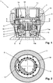
- FIG. 1 shows a sectional view of a control knob 1 according to the invention with a non-rotatable member 2, a rotatable member 3 and a hub 4.
- the control knob 1 is attached to a shaft, not shown.
- This shaft is either fixed or tiltable stored in the vehicle.
- the control knob 1 is used in addition to its own functionality as a handle of a joystick.
- An annular formed portion of the rotatable member 3 forms a portion of the outside of the operating knob 1 and is rotatable there by the user.
- the running in the interior of the control knob 1 region of the rotatable member 3 is connected via a bearing 12, for example a ball bearing, with the non-rotatable part 2 of the control knob.
- the rotatable part 3 does not extend to the top of the control knob 1, which ensures that the rotatable part 3 is not inadvertently adjusted by the user when tilting or pressing the control knob 1.
- a locking contour 5 is introduced. This is especially in FIG. 2 to recognize, which represents an alternative sectional view of the control knob 1 along the line AA.
- a prestressed detent spring 7 which is elastically deformed during the rotation of the rotatable member 3 by the flanks of the locking contour 5 and the rotation opposes such a force. This force is perceived by the user as a rotary haptic and generates detent positions of the rotatable part 3.
- the rotation of the rotatable part 3 can be blocked by means of a locking device.
- the locking device consists of the two electromagnets 7 and 10, by means of which one ball in each case can be brought into engagement with a blocking contour 6 arranged on the rotatable part 3.
- the electromagnet 7 moves the ball 9, which is moved by the electromagnet 10 ball in FIG. 1 covered.
- the blocking contour 6 is arranged on an annular end face of the rotatable part 3.
- Each of the electromagnets 7 and 10 blocks a rotational direction of the rotatable member 3.
- the electromagnet 10 is pushed onto a U-shaped iron core with the legs 11a and 11b. By a different energization of the electromagnet 10, the direction of the magnetic field in the iron core is reversible.
- an unillustrated permanent magnet moves between an upper position in front of leg 11a and a lower position in front of leg 11b.
- a permanent magnet also by means of the electromagnet 7 is a permanent magnet, not shown, movable between an upper and a lower position.
- the movement of the electromagnet is followed by a magnetizable ball 9.
- the ball 9 engages the locking contour 6, thus blocking the rotation of the rotatable member 3.
- the control knob 1 further comprises rotary encoder, by means of which a rotation of the rotatable member is detectable.
- the rotary encoder consists of a light barrier 19 arranged in the rotationally fixed part 2 and a coding ring 18 arranged on the rotatable part 3.
- the coding ring 18 moves through the detection range of the light barrier 19 when the rotary part 3 rotates the output signal of the light barrier 19, from which the angle of rotation and the direction of rotation of the rotatable part 3 is determined. This provision is known to the person skilled in the art and therefore will not be described here.
- the control knob 1 also has a button with which, for example, a selected function of the onboard computer can be activated.
- the button consists of a key cap 13 which is hineinind Wegbar in the non-rotatable part 2, and a switch 14.
- the switch 14 detects on the one hand actuation of the key cap 13 and brings this on the other hand after their operation in their initial position.
- the circuit board 15 carries the electronics 16 of the control knob, which controls all components of the control knob 1 and evaluates the signals of the signal generator. Furthermore it makes the electronic contact to the on-board electronics of the motor vehicle, for example via a data bus.
- the electronics 16 receives information from the on-board computer about which functions the control knob 1 is currently to provide, and controls the components such as the electromagnets 7 and 10 accordingly.
- the electronics 16 evaluates the signal from the photocell 19 and the switch 14.
- the evaluated data is transmitted via the data bus to the on-board electronics of the motor vehicle.
- the control knob 1 is thus used with only minor modifications in a variety of vehicles. Only the interface for the connection to the vehicle bus has to be adapted:
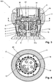
- FIGS. 3 and 4 show a modification of the control knob 1 analogous to the Figures 1 and 2 ,
- the structure of the control knob 100 corresponds essentially to that of the control knob 1, but without the key cap 13 and the switch 14.
- the same or equivalent components are provided with the same reference numerals.
- the area that forms the key cap 13 in the control knob 1 is connected to the control knob 100 rigidly connected to the rotationally fixed part 2.
- the control knob 100 with its non-rotatable part 2 and its rotatable part 3 translationally relative to the hub 4 and thus displaceable along the shaft.
- the tactile function is performed by pressing the substantially entire control knob 100.
- the contact domes of the switches 20 are pressed against a fixed plate of the hub 4 and thus trigger a tactile function, which is detected by the electronics 16.
- the switches 20 simultaneously bring a restoring force, which return the control knob 100 after pressing in its original position.
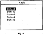
- FIG. 5 shows the exemplary application of the control knob 1 or 100.
- a car radio to be operated in which a radio station is selected from a list.
- the on-board computer transmits the electronics 16 of the control knob 1 or 100 that it should allow five locking positions of the rotatable part 3 and the current selection of the first position corresponds. Then, the electronics 16 blocks the rotation of the rotatable member 3 counterclockwise by energizing the electromagnet 7 so that the ball 9 comes into engagement with the locking contour 6.
- the electronics 16 determine this on the basis of the output signal of the light barrier 19. The electronics 16 signals this rotation to the on-board computer, which then sets the marking on station 2. The further rotation of the rotatable member 3 in the clockwise direction is possible until station 5 is marked and by means of the electromagnet 10 a further rotation of the rotatable member 3 is prevented. If the user selects a station by pressing the key cap 13 or the entire control knob 100, the electronics 16 transmits this to the on-board computer, which then switches to the selected radio station.
Landscapes
- Engineering & Computer Science (AREA)
- Physics & Mathematics (AREA)
- General Physics & Mathematics (AREA)
- Automation & Control Theory (AREA)
- Chemical & Material Sciences (AREA)
- Combustion & Propulsion (AREA)
- Transportation (AREA)
- Mechanical Engineering (AREA)
- Mechanical Control Devices (AREA)
- Switches With Compound Operations (AREA)
- Rotary Switch, Piano Key Switch, And Lever Switch (AREA)
Description
- Die vorliegende Erfindung betrifft einen Bedienknopf für ein Kraftfahrzeug, der eine Vielzahl von Funktionen wie die Erzeugung einer Haptik und verschiedene Betätigungsfunktionen in sich vereint.
- In Kraftfahrzeugen werden verschiedenste Funktionen zunehmend über ein einziges Menü in Verbindung mit einem Bordcomputer bedient. Dazu wird oftmals ein zentrales Bedienelement eingesetzt, das eine Vielzahl von Eingabefunktionen in sich vereint, beispielsweise Taster und Drehgeber. Dabei ist die Haptik des Bedienknopfes häufig dynamisch anpassbar, beispielsweise in Form von exponierten Rasten oder von Endanschlägen.
- Ein Nachteil der bisher bekannten gattungsgemäßen Bedienelemente ist die aufwändige Adaption an den jeweiligen Fahrzeugtyp. Es ist daher die Aufgabe der vorliegenden Erfindung, einen Bedienknopf bereitzustellen; der eine Vielzahl Funktionalitäten vereint und einfach an das Kraftfahrzeug anpassbar ist.
- Gelöst wird diese Aufgabe durch die Merkmale des Patentanspruchs 1. Weitere vorteilhafte Ausgestaltungsformen sind in den abhängigen Patentansprüchen angegeben.
- Ein erfindungsgemäßer Bedienknopf zur Verwendung an einem Kraftfahrzeug weist eine Nabe zur Anbringung des Bedienknopfes auf einer Welle, einen drehfesten Teil, einen drehbaren Teil, einen Drehwinkelgeber, Mittel zur Erzeugung einer Drehhaptik sowie eine Elektronik, mittels der die im Bedienknopf angeordneten Komponenten ansteuerbar und die Signale der Signalgeber auswertbar sind und über die der Bedienknopf an eine Elektronik des Kraftfahrzeugs anschließbar ist, auf.
- Mit seiner Nabe wird der Bedienknopf auf die Welle aufgesteckt und so im Kraftfahrzeug befestigt. Die Nabe ist entweder starr oder in eine oder mehrere Richtungen kippbar gelagert, so dass bei einer kippbar gelagerten Welle der Bedienknopf als Handhabe eines Joysticks dient. Der drehfeste Teil des Bedienknopfes ist nicht um die Welle drehbar, während der drehbare Teil relativ zum drehfesten Teil drehbar angeordnet ist. Bei dem drehbaren Teil handelt es sich bevorzugt um einen Ring, der einen Teil der Umfangsfläche des Bedienknopfes bildet.
- Mittels des Drehwinkelgebers ist die Drehstellung des drehbaren Teils detektierbar. Dazu ist der Drehwinkelgeber als Absolutwertgeber oder als inkrementeller Drehwinkelgeber ausgebildet. Ein Absolutwertgeber liefert den absoluten Drehwinkel des drehbaren Teils, während ein inkrementeller Drehwinkelgeber eine Drehung um ein bestimmtes Maß signalisiert. Das oder die Mittel zur Erzeugung einer Drehhaptik geben dem Benutzer eine taktile Rückmeldung über die Betätigung des drehbaren Teils.
- Die Elektronik dient der Ansteuerung der im Bedienknopf angeordneten Komponenten wie beispielsweise den Mitteln zur Erzeugung der Drehhaptik. Außerdem wertet die Elektronik die Signale der Signalgeber, beispielsweise des Drehwinkelgebers, aus und bereitet diese so auf, dass sie direkt an die Bordelektronik des Kraftfahrzeugs übertragen werden können.
- Dabei erfolgt die Anbindung des Bedienknopfes an die Bordelektronik bevorzugt über einen Datenbus. Die Elektronik des Bedienknopfes ist nun vorteilhaft so ausgestaltet, das sie die gewünschte Haptik des Bedienknopfes über den Datenbus empfängt und die Komponenten entsprechend ansteuert sowie Informationen über eine Betätigung des Bedienknopfes in einer entsprechenden Nachricht über den Datenbus versendet. Der Bedienknopf ist somit an einen Fahrzeugtyp adaptierbar, indem die Elektronik entsprechend der Bordelektronik gestaltet beziehungsweise programmiert wird.
- In einer Ausgestaltung der Erfindung wird ein Mittel zur Erzeugung der Drehhaptik durch eine mit einer Rastkontur zusammenwirkende Rastfeder gebildet. Dabei greift die Rastfeder in die Rastkontur ein und wird bei der Drehung des drehbaren Teils verformt, wodurch sich ein definierter Drehwiderstand ergibt. Dieses Prinzip zur Rasterzeugung ist dem Fachmann geläufig und wird daher nicht weiter ausgeführt. Bevorzugt ist die Rastfeder im drehfesten Teil des Bedienknopfes angeordnet und die Rastkontur in den drehbaren Teil eingebracht.
- In einer weiteren Ausgestaltungsform ist im Bedienknopf ein zustellbarer Stößel angeordnet, der in Eingriff mit der Rastkontur bringbar ist. Ist der zustellbare Stößel im Eingriff mit der Rastkontur, so wird der Drehung des drehbaren Teils eine zusätzliche Kraft entgegen gesetzt. Diese Gegenkraft nimmt der Benutzer als besondere Rast wahr, beispielsweise als Mittenrast. Der zustellbare Stößel wird beispielsweise mittels eines Elektrönmagneten in Eingriff mit der Rastkontur gebracht beziehungsweise aus diesem entfernt. Eine detaillierte Beschreibung des Funktionsprinzips findet sich in der deutschen Patentanmeldung
10 2005 043 587.4 der Anmelderin. - In einer weiteren Ausgestaltungsform der Erfindung weist der Bedienknopf eine Sperrvorrichtung zum Sperren der Drehung des drehbaren Teils auf. Durch diese Sperrvorrichtung werden dynamisch zuschaltbare und frei positionierbare Endanschläge realisiert, die zur Erzeugung der Drehhaptik beitragen. Bevorzugt wird die Sperrvorrichtung durch mindestens einen Elektromagneten gebildet, durch den eine Kugel in Eingriff mit einer am drehbaren Teil angeordneten Sperrkontur bringbar ist. Der Elektromagnet zieht dabei die Kugel in eine Position, in der sie zwischen der Sperrkontur im drehbaren Teil und dem drehfesten Teil verklemmt und somit eine weitere Drehung des drehbaren Teils blockiert. Das Funktionsprinzip und die Ausgestaltung einer derartigen Sperrvorrichtung sind detailliert in der deutschen Patentanmeldung
10 2005 024 883.5 der Anmelderin beschrieben. - In einer anderen Ausgestaltung der Sperrvorrichtung wird ein Permanentmagnet mittels eines Elektromagneten zwischen zwei Positionen verfahren. Eine Kugel folgt der Position des Permanentmagneten und wechselt somit ebenfalls zwischen zwei Positionen. In einer Position ist die Kugel zwischen dem drehfesten Teil des Bedienknopfes und der Sperrkontur verklemmt, so dass die Drehung des drehbaren Teils blockiert wird. In der zweiten Position der Kugel wird die Drehung freigegeben. Das Funktionsprinzip sowie beispielhafte Ausgestaltungsformen einer derartigen Sperrvorrichtung werden in der deutschen Patentanmeldung
10 2006 015 294.8 der Anmelderin detailliert beschrieben. - Das Dokument
DE 20 219 655 U zeigt den Oberbegriff des Anspruchs 1. - In der Erfindung ist die Sperrkontur an einer ringförmig ausgebildeten Stirnfläche des drehbaren Teils angeordnet. Die Stirnfläche befindet sich beispielsweise als Fortsatz eines vom Benutzer bedienbaren Bereiches des drehbaren Teils im Inneren des Bedienknopfes. Bevorzugt ist die Sperrkontur so ausgestaltet, dass die durch sie ermöglichten Endanschläge mit den durch die Rastkontur und die Rastfeder erzeugten Rastpositionen übereinstimmen.
- In einer weiteren Ausführungsform der Erfindung ist auf der Oberseite des Bedienknopfes ein Symbol angeordnet. Bevorzugt wird dieses Symbol durch ein Leuchtmittel beleuchtet, wobei insbesondere unterschiedliche Such- und Funktionsbeleuchtungen erzeugbar sind. Die Ansteuerung des Leuchtmittels erfolgt ebenfalls durch die Elektronik des Bedienknopfes.
- In einer Abwandlung der vorstehenden Ausführungsform sind im Bedienknopf Mittel zur Anzeige eines veränderlichen Symbols auf der Oberseite des Bedienknopfes angeordnet
- Diese Mittel bestehen beispielsweise aus einem Display und einer oder mehreren Lichtquellen zur Durchleuchtung des Displays. Bevorzugt sind in der Elektronik des Bedienknopfes, die das Display oder die Lichtquellen ansteuert, verschiedene Symbole hinterlegt. Über den Datenbus teilt die Bordelektronik des Kraftfahrzeugs dem Bedienknopf mit, welches des Symbole anzuzeigen ist. Alternativ oder zusätzlich überträgt die Bordelektronik über den Datenbus das vollständige Symbol in einem festgelegten Format an den Bedienknopf. Dadurch ist es möglich, beispielsweise bei einem Update der Betriebssoftware des Kraftfahrzeugs neue Symbole hinzuzufügen, die bei der Montage des Bedienknopfes im Kraftfahrzeug noch nicht zur Verfügung gestanden haben. Mögliche Ausgestaltungsformen der Mittel zur Anzeige des veränderlichen Symbols sind den deutschen Patentanmeldungen
103 42 142.4 oder10 2005 043 588.2 der Anmelderin zu entnehmen. - In einer Ausgestaltungsform der Erfindung weist der Bedienknopf einen Taster auf, insbesondere an der Oberseite des Bedienknopfes. Dazu ist eine Tastenkappe, die bevorzugt einen Teil der Oberseite des Bedienknopfes bildet, relativ zum restlichen Bedienknopf translatorisch bewegbar. Die Betätigung des Tasters ist mit Hilfe eines Schaltmittels detektierbar. Das Schaltmittel wirkt als Signalgeber, dessen Signal die Elektronik des Bedienknopfes auswertet und an die Bordelektronik des Kraftfahrzeugs übermittelt.
- In einer alternativen Ausgestaltungsform ist der Bedienknopf entlang der Welle relativ zur Nabe verschiebbar. Dadurch wird nicht eine Tastenkappe relativ zum Rest des Bedienknopfes bewegt, sondern der gesamte Bedienknopf relativ zu der Nabe, mit der er auf der Welle befestigt ist.
- Die Elektronik des Bedienelementes empfängt einerseits Befehle von der Bordelektronik über das gewünschte Verhalten des Bedienelementes. Daraus erzeugt sie Ansteuersignale für die Komponenten wie einen zustellbaren Stößel, einen Elektromagnet einer Sperrvorrichtung, ein Leuchtmittel oder ein Display. Andererseits wertet die Elektronik die Ausgangssignale der Komponenten wie dem Drehwinkelgeber und einem Schalter oder Taster aus und überträgt die entsprechenden Informationen an die Bordelektronik.
- Die vorliegende Erfindung soll anhand zweier Ausführungsbeispiele näher erläutert werden.
- Dabei zeigt
- Figur 1
- eine Schnittdarstellung eines erfindungsgemäßen Bedienknopfes,
- Figur 2
- eine andere Schnittdarstellung des Bedienknopfes aus
Figur 1 entlang der Linie A-A, - Figur 3
- die Schnittdarstellung einer anderen Ausführungsform eines erfindungsgemäßen Bedienknopfes,
- Figur 4
- eine andere Schnittdarstellung des Bedienknopfes aus der
Figur 3 entlang der Linie B-B und - Figur 5
- die Darstellung eines Displays bei Bedienung eines Radios.
-
Figur 1 zeigt eine Schnittdarstellung eines erfindungsgemäßen Bedienknopfes 1 mit einem drehfesten Teil 2, einem drehbaren Teil 3 und einer Nabe 4. Mittels der Nabe 4 wird der Bedienknopf 1 auf eine nicht dargestellten Welle aufgesteckt. Diese Welle ist entweder fest oder kippbar im Kraftfahrzeug gelagert. Bei einer kippbaren Lagerung dient der Bedienknopf 1 zusätzlich zu seiner eigenen Funktionalität als Handhabe eines Joysticks. - Ein ringförmig ausgebildeter Bereich des drehbaren Teils 3 bildet einen Bereich der Außenseite des Bedienknopfes 1 und ist dort vom Benutzer drehbar. Der im Inneren des Bedienknopfes 1 verlaufende Bereich des drehbaren Teils 3 ist über ein Lager 12, beispielsweise ein Kugellager, mit dem drehfesten Teil 2 des Bedienknopfes verbunden. Der drehbare Teil 3 reicht nicht bis an die Oberseite des Bedienknopfes 1, wodurch erreicht wird, dass der drehbare Teil 3 beim Kippen oder Drücken des Bedienknopfes 1 vom Benutzer nicht unbeabsichtigt verstellt wird.
- An einem inneren Umfang des drehbaren Teils 3 ist eine Rastkontur 5 eingebracht. Diese ist insbesondere in
Figur 2 zu erkennen, die eine alternative Schnittdarstellung des Bedienknopfes 1 entlang des Linie A-A darstellt. In die Rastkontur 5 greift eine vorgespannte Rastfeder 7 ein, die bei der Drehung des drehbaren Teils 3 durch die Flanken der Rastkontur 5 elastisch verformt wird und der Drehung so eine Kraft entgegensetzt. Diese Kraft ist vom Benutzer als Drehhaptik wahrnehmbar und erzeugt Rastpositionen des drehbaren Teils 3. - Die Drehung des drehbaren Teils 3 ist mittels einer Sperrvorrichtung sperrbar. Die Sperrvorrichtung besteht aus den beiden Elektromagneten 7 und 10, mittels derer jeweils eine Kugel in Eingriff mit einer am drehbaren Teil 3 angeordneten Sperrkontur 6 bringbar ist. Der Elektromagnet 7 bewegt die Kugel 9, die vom Elektromagneten 10 bewegte Kugel ist in
Figur 1 verdeckt. Die Sperrkontur 6 ist an einer ringförmig ausgebildeten Stirnfläche des drehbaren Teils 3 angeordnet. Jeder der Elektromagneten 7 und 10 sperrt eine Drehrichtung des drehbaren Teils 3. Der Elektromagnet 10 ist auf einen U-förmigen Eisenkern mit den Schenkeln 11a und 11b aufgeschoben. Durch eine unterschiedliche Bestromung des Elektromagneten 10 ist die Richtung des Magnetfeldes im Eisenkern umkehrbar. Je nach Richtung des Magnetfeldes im Eisenkern bewegt sich ein nicht dargestellter Permanentmagnet zwischen einer oberen Position vor Schenkel 11 a und einer unteren Position vor Schenkel 11b. Zur Erläuterung des Funktionsprinzips der Sperrvorrichtung wurde der Eisenkern des Elektromagneten 7 inFigur 1 weggelassen. Auch mittels des Elektromagneten 7 ist ein nicht dargestellter Permanentmagnet zwischen einer oberen und einer unteren Position verfahrbar. Der Bewegung des Elektromagneten folgt eine magnetisierbare Kugel 9. In der oberen Position des Permanentmagneten und damit der Kugel 9 greift die Kugel 9 in die Sperrkontur 6 ein und blockiert so die Drehung des drehbaren Teils 3. In der unteren Position des Permanentmagneten liegt die Kugel 9 in der Tasche 8, wo sie die Drehung des drehbaren Teils 3 nicht behindert. - Der Bedienknopf 1 weist weiterhin Drehwinkelgeber auf, mittels dessen eine Drehung des drehbaren Teils detektierbar ist. Im vorliegenden Ausführungsbeispiel besteht der Drehwinkelgeber aus einer im drehfesten Teil 2 angeordneten Lichtschranke 19 und einem am drehbaren Teil 3 angeordneten Kodierring 18. Der Kodierring 18 bewegt sich bei einer Drehung der drehbaren Teils 3 durch den Erfassungsbereich der Lichtschranke 19. Durch Ausnehmungen im Kodierring 18 verändert sich das Ausgangssignal der Lichtschranke 19, woraus der Drehwinkel und die Drehrichtung des drehbaren Teils 3 bestimmt wird. Diese Bestimmung ist dam Fachmann bekannt und wird daher hier nicht näher ausgeführt.
- Der Bedienknopf 1 weist zusätzlich einen Taster auf, mit dem beispielsweise eine ausgewählte Funktion des Bordcomputers aktivierbar ist. Der Taster besteht aus einer Tastenkappe 13, die in den drehfesten Teil 2 hineindrückbar ist, und einem Schalter 14. Der Schalter 14 detektiert einerseits eine Betätigung der Tastenkappe 13 und bringt diese andererseits nach ihrer Betätigung in ihre Ausgangslage zurück.
- Die Leiterplatte 15 trägt die Elektronik 16 des Bedienknopfes, die sämtliche Komponenten des Bedienknopfes 1 ansteuert und die Signale der Signalgeber auswertet. Darüber hinaus stellt sie den elektronischen Kontakt zur Bordelektronik des Kraftfahrzeugs her, beispielsweise über einen Datenbus. Die Elektronik 16 erhält vom Bordcomputer Informationen darüber, welche Funktionen der Bedienknopf 1 aktuell bereitstellen soll, und steuert die Komponenten wie beispielsweise die Elektromagneten 7 und 10 entsprechend an. Darüber hinaus wertet die Elektronik 16 das Signal der Lichtschranke 19 und des Schalters 14 aus. Die ausgewerteten Daten werden über den Datenbus an die Bordelektronik des Kraftfahrzeugs übertraggen. Der Bedienknopf 1 ist also mit nur geringen Modifikationen in einer Vielzahl von Kraftfahrzeugen einsetzbar. Lediglich die Schnittstelle für die Anbindung an den Fahrzeugbus muss angepasst werden:
- Die
Figuren 3 und 4 zeigen eine Modifikation des Bedienknopfes 1 analog zu denFiguren 1 und 2 . Der Aufbau des Bedienknopfes 100 entspricht im Wesentlichen dem des Bedienknopfes 1, jedoch ohne die Tastenkappe 13 und den Schalter 14. Gleiche oder gleichwirkende Komponenten sind mit den gleichen Bezugszeichen versehen. Der Bereich, den bei Bedienknopf 1 die Tastenkappe 13 bildet, ist beim Bedienknopf 100 starr mit dem drehfesten Teil 2 verbunden. Dahingegen ist der Bedienknopf 100 mit seinem drehfesten Teil 2 und seinem drehbaren Teil 3 translatorisch gegenüber der Nabe 4 und somit entlang der Welle verschiebbar. Damit wird die Tastfunktion durch Drücken des im Wesentlichen gesamten Bedienknopfes 100 ausgeführt. Bei Drücken des Bedienknopfes 100 werden die Kontaktdome der Schalter 20 gegen eine feststehende Platte der Nabe 4 gedrückt und lösen somit eine Tastfunktion aus, die von der Elektronik 16 detektiert wird. Die Schalter 20 bringen gleichzeitig eine Rückstellkraft auf, die den Bedienknopf 100 nach dem Drücken in seine Ausgangsposition zurückbringen. -
Figur 5 zeigt die beispielhafte Anwendung des Bedienknopfes 1 beziehungsweise 100. Im vorliegenden Beispiel soll ein Autoradio bedient werden, in dem ein Radiosender aus einer Liste ausgewählt wird. InFigur 5 ist zu erkennen, dass aktuell die fünf Radiosender Station 1 bis Station 5 empfangbar sind. Momentan ist der Name der Station 1 hervorgehoben. Der Bordcomputer übermittelt der Elektronik 16 des Bedienknopfes 1 bzw. 100, dass sie fünf Rastpositionen des drehbaren Teils 3 zulassen soll und die aktuelle Auswahl der ersten Position entspricht. Daraufhin blockiert die Elektronik 16 die Drehung des drehbaren Teils 3 gegen den Uhrzeigersinn, indem sie den Elektromagneten 7 derart bestromt, dass die Kugel 9 in Eingriff mit der Sperrkontur 6 gelangt. Dreht der Benutzer den drehbaren Teil 3 eine Rast im Uhrzeigersinn, so ermittelt die Elektronik 16 dies anhand des Ausgangssignals der Lichtschranke 19. Die Elektronik 16 signalisiert diese Drehung dem Bordcomputer, der daraufhin die Markierung auf Station 2 setzt. Die weitere Drehung des drehbaren Teils 3 im Uhrzeigersinn ist möglich, bis Station 5 markiert ist und mittels des Elektromagneten 10 eine weitere Drehung des drehbaren Teils 3 verhindert wird. Wählt der Benutzer eine Station durch Drücken der Tastenkappe 13 bzw. des gesamten Bedienknopfes 100 aus, so übermittelt die Elektronik 16 dies an den Bordcomputer, der daraufhin zum ausgewählten Radiosender wechselt. - Die vorausgegangenen Ausführungsbeispiele sind rein exemplarisch und insofern nicht beschränkend. Dies betrifft insbesondere die Verwendung des erfindungsgemäßen Bedienknopfes, die sich über die Auswahl eines Radiosenders hinaus auf jede Bedienung eines Bordcomputers oder eines anderen Gerätes erschreckt. Ebenso kann der Aufbau des Bedienknopfes von den in den
Figuren 1 bis 4 dargestellten Formen abweichen, ohne den Erfindungsgedanken zu verlassen. So kann beispielsweise in die Oberseite des Bedienknopfes ein Symbol, insbesondre ein beleuchtbares Symbol eingelassen sein. Weiterhin ist es möglich, mittels eines Displays ein variables Symbol auf die Oberseite des Bedienknopfes zu projizieren. Weiterhin können im Bedienknopf Mittel zur Erzeugung einer exponierten Rast, beispielsweise einer Mittenrast, vorhanden sein. Die Ansteuerung dieser zusätzlichen Komponenten wird ebenfalls von der Elektronik des Bedienknopfes übernommen.
Claims (9)
- Bedienknopf (1, 100) zur Verwendung in einem Kraftfahrzeug, aufweisend eine Nabe (4) zur Anbringung des Bedienknopfes (1, 100) auf einer Welle, einen drehfesten Teil (2), einen drehbaren Teil (3), einen Drehwinkelgeber, Mittel zur Erzeugung einer Drehhaptik (5, 17) sowie eine Elektronik (16), mittels der die im Bedienknopf (1, 100) angeordnete Komponenten (7, 10) ansteuerbar und die Signale der Signalgeber (14, 19, 20) auswertbar sind, wobei der Bedienknopf (1, 100) über die Elektronik an die Bordelektronik des Kraftfahrzeugs über einen Datenbus anschließbar ist, wobei die Elektronik (16) ausgelegt ist, die gewünschte Haptik über den Datenbus zu empfangen, die Komponenten (7, 10) entsprechend anzusteuern und Informationen über die Betätigung des Bedienknopfs über den Datenbus zu versenden, dadurch gekennzeichnet, dass der drehbare Teil (3) ein Ring ist, in dessen Innerem der drehfeste Teil (2) angeordnet ist.
- Bedienknopf (1, 100) nach Anspruch 1, dadurch gekennzeichnet, dass das Mittel zur Erzeugung der Drehhaptik durch eine mit einer Rastkontur (5) zusammenwirkende Rastfeder (17) gebildet wird.
- Bedienknopf (1, 100) nach Anspruch 2, gekennzeichnet durch einen zustellbaren Stößel, der in Eingriff mit der Rastkontur (5) bringbar ist.
- Bedienknopf (1, 100) nach einem der Ansprüche 1 bis 3, gekennzeichnet durch eine Sperrvorrichtung zum Sperren der Drehung des drehbaren Teils des Bedienknopfes.
- Bedienknopf (1, 100) nach Anspruch 4, dadurch gekennzeichnet, dass die Sperrvorrichtung durch mindestens einen Elektromagneten (7,10) gebildet wird, durch den eine Kugel (9) in Eingriff mit einer am drehbaren Teil (3) angeordneten Sperrkontur (6) bringbar ist.
- Bedienknopf (1, 100) nach Anspruch 5, dadurch gekennzeichnet, dass die Sperrkontur (6) an einer ringförmig ausgebildeten Stirnfläche des drehbaren Teils (3) angeordnet ist.
- Bedienknopf (1, 100) nach einem der Ansprüche 1 bis 6, gekennzeichnet durch Mittel zur Anzeige eines veränderlichen Symbols auf der Oberseite des Bedienknopfes.
- Bedienknopf (1, 100) nach einem der Ansprüche 1 bis 7, gekennzeichnet durch einen Taster, insbesondere an der Oberseite des Bedienknopfes.
- Bedienknopf (1, 100) nach einem der Ansprüche 1 bis 7, dadurch gekennzeichnet, dass der Bedienknopf (1, 100) entlang der Welle relativ zur Nabe (4) verschiebbar ist.
Applications Claiming Priority (3)
| Application Number | Priority Date | Filing Date | Title |
|---|---|---|---|
| DE102005033552 | 2005-07-19 | ||
| DE102006018518.8A DE102006018518B4 (de) | 2005-07-19 | 2006-04-21 | Bedienknopf mit integrierter Funktionalität |
| PCT/EP2006/007045 WO2007009745A2 (de) | 2005-07-19 | 2006-07-18 | Bedienknopf mit integrierter funktionalität |
Publications (2)
| Publication Number | Publication Date |
|---|---|
| EP1961025A2 EP1961025A2 (de) | 2008-08-27 |
| EP1961025B1 true EP1961025B1 (de) | 2016-03-30 |
Family
ID=37460339
Family Applications (1)
| Application Number | Title | Priority Date | Filing Date |
|---|---|---|---|
| EP06776276.5A Active EP1961025B1 (de) | 2005-07-19 | 2006-07-18 | Bedienknopf mit integrierter funktionalität |
Country Status (4)
| Country | Link |
|---|---|
| US (1) | US7579559B2 (de) |
| EP (1) | EP1961025B1 (de) |
| CN (1) | CN101223618B (de) |
| WO (1) | WO2007009745A2 (de) |
Families Citing this family (30)
| Publication number | Priority date | Publication date | Assignee | Title |
|---|---|---|---|---|
| DE102008007930A1 (de) * | 2008-02-07 | 2009-08-13 | Ford Global Technologies, LLC, Dearborn | Lichtschalter für Kraftfahrzeuge |
| US8217742B2 (en) * | 2008-10-07 | 2012-07-10 | Exelis, Inc. | Dual independent push button rotary knob assembly |
| US20100084249A1 (en) * | 2008-10-07 | 2010-04-08 | Itt Manufacturing Enterprises, Inc. | Snap-on, push button, rotary magnetic encoder knob assembly |
| FR2937434B1 (fr) * | 2008-10-20 | 2013-01-04 | Dav | Bouton de commande multifonction. |
| DE112009003296B4 (de) | 2008-12-03 | 2019-01-31 | Kelsey-Hayes Company | Steuerknopf und Verfahren zum Steuern eines Berührungssteuerknopfes |
| DE102009042497A1 (de) * | 2009-09-15 | 2011-03-31 | Dr. Ing. H.C. F. Porsche Aktiengesellschaft | Lenkrad mit mindestens einem Schaltpaddle |
| FR2950166B1 (fr) * | 2009-09-16 | 2015-07-17 | Dav | Dispositif de commande rotatif a retour haptique |
| DE102010039415A1 (de) * | 2010-08-17 | 2012-02-23 | E.G.O. Elektro-Gerätebau GmbH | Bedieneinrichtung und Bedienverfahren |
| US10502271B2 (en) | 2010-09-15 | 2019-12-10 | Inventus Engineering Gmbh | Haptic operating device with a rotating element and method for operating electronic equipment with the haptic operating device |
| US10007290B2 (en) | 2010-09-15 | 2018-06-26 | Inventus Engineering Gmbh | Haptic operating device with a rotating element and method |
| JP5626591B2 (ja) * | 2011-04-14 | 2014-11-19 | アルプス電気株式会社 | 入力装置 |
| DE102011083524B4 (de) * | 2011-09-27 | 2017-04-06 | Behr-Hella Thermocontrol Gmbh | Dreh-/Drück-Bedienvorrichtung für ein Mensch-Maschine-Interface |
| US20130113465A1 (en) * | 2011-11-04 | 2013-05-09 | Delphi Technologies, Inc. | Multiple function control knob assembly |
| US8796566B2 (en) | 2012-02-28 | 2014-08-05 | Grayhill, Inc. | Rotary pushbutton and touchpad device and system and method for detecting rotary movement, axial displacement and touchpad gestures |
| US9006591B2 (en) | 2012-11-13 | 2015-04-14 | Electrolux Home Products, Inc. | Appliance control knob support |
| US9268356B2 (en) | 2013-03-15 | 2016-02-23 | Touchsensor Technologies, Llc | Modular knob system |
| ES2539417B1 (es) * | 2015-03-03 | 2016-01-25 | Seat, S.A. | Dispositivo actuador para unidad de control y procedimiento de fijación de un dispositivo actuador para unidad de control |
| CN110456855B (zh) | 2016-09-26 | 2020-10-30 | 深圳市大疆创新科技有限公司 | 拨轮机构及使用该拨轮机构的控制装置 |
| CN106989366A (zh) * | 2017-03-28 | 2017-07-28 | 苏州佳世达电通有限公司 | 旋转调光装置 |
| DE102017206785A1 (de) * | 2017-04-21 | 2018-10-25 | Bayerische Motoren Werke Aktiengesellschaft | Bedieneinrichtung zum Steuern von Funktionen eines Kraftfahrzeugs und Verfahren zum Betreiben einer solchen |
| CN207529869U (zh) * | 2017-12-18 | 2018-06-22 | 东莞辰达电器有限公司 | 一种带显示功能的旋钮 |
| CN108227822A (zh) * | 2018-02-08 | 2018-06-29 | 广州可酷动漫科技有限公司 | 一种旋转转换按键 |
| CN109324656B (zh) * | 2018-11-12 | 2024-06-25 | 深圳市思通汽车电子有限公司 | 智联控制旋钮 |
| TWI676196B (zh) * | 2018-11-19 | 2019-11-01 | 國家中山科學研究院 | 數字編碼裝置 |
| KR102676723B1 (ko) * | 2019-11-14 | 2024-06-18 | 현대자동차주식회사 | 전자식 변속시스템용 다이얼타입 변속조작장치 |
| KR102812073B1 (ko) | 2019-11-14 | 2025-05-22 | 현대자동차주식회사 | 다이얼타입 변속조작장치용 간접조명장치 |
| KR102730517B1 (ko) | 2019-11-14 | 2024-11-13 | 현대자동차주식회사 | 다이얼타입 변속조작장치용 래틀저감장치 |
| CN116868144A (zh) * | 2021-03-25 | 2023-10-10 | 阿尔卑斯阿尔派株式会社 | 旋转换挡器 |
| DE102021128013B4 (de) * | 2021-10-27 | 2023-06-29 | Preh Gmbh | Eingabegerät mit dreh- oder schwenkbeweglich achsengelagerter Handhabe |
| IT202200007877A1 (it) * | 2022-04-21 | 2023-10-21 | Ferrari Spa | Manopola di comando per un autoveicolo |
Citations (1)
| Publication number | Priority date | Publication date | Assignee | Title |
|---|---|---|---|---|
| DE20014425U1 (de) * | 1999-08-18 | 2001-01-04 | Immersion Corp., San Jose, Calif. | Mechanismen für Steuerknöpfe und andere Schnittstellenvorrichtungen |
Family Cites Families (12)
| Publication number | Priority date | Publication date | Assignee | Title |
|---|---|---|---|---|
| DE4432015C2 (de) * | 1994-09-08 | 2003-08-28 | Beissbarth Gmbh | Verfahren zur Bedienung einer Auswuchtmaschine und Bedienelement zur Durchführung des Verfahrens |
| JP3403603B2 (ja) * | 1997-03-26 | 2003-05-06 | 矢崎総業株式会社 | コンビネーションスイッチ |
| JP4318354B2 (ja) * | 1999-10-04 | 2009-08-19 | ナイルス株式会社 | レバースイッチ |
| JP3831590B2 (ja) * | 2000-08-22 | 2006-10-11 | アルプス電気株式会社 | 複合型スイッチ装置 |
| US6534732B2 (en) * | 2001-04-19 | 2003-03-18 | Methode Electronics, Inc. | Multifunctional windshield wiper stalk switch |
| DE10120691A1 (de) * | 2001-04-27 | 2002-11-21 | Siemens Ag | Bedieneinheit,insbesondere für die Bedienung eines Multimediasystems in einem Kraftfahrzeug |
| DE20219655U1 (de) * | 2001-12-20 | 2003-03-13 | Leopold Kostal GmbH & Co KG, 58507 Lüdenscheid | Schalteinrichtung |
| JP4084138B2 (ja) * | 2002-09-05 | 2008-04-30 | アルプス電気株式会社 | 回転操作型電気部品 |
| DE10341016B4 (de) * | 2003-09-03 | 2016-11-17 | Continental Automotive Gmbh | Bedienelement, insbesondere für ein Multimediasystem eines Kraftfahrzeugs |
| JP4031775B2 (ja) * | 2004-04-28 | 2008-01-09 | 三菱重工業株式会社 | 車両用空調装置のダイヤル式スイッチ機構 |
| JP2007035378A (ja) * | 2005-07-25 | 2007-02-08 | Mic Electron Co | 複合スイッチ |
| US7439458B2 (en) * | 2006-08-25 | 2008-10-21 | Delphi Technologies, Inc. | Five-way directional push button on a rotary knob |
-
2006
- 2006-07-18 EP EP06776276.5A patent/EP1961025B1/de active Active
- 2006-07-18 WO PCT/EP2006/007045 patent/WO2007009745A2/de not_active Ceased
- 2006-07-18 CN CN200680026214XA patent/CN101223618B/zh active Active
-
2008
- 2008-01-22 US US12/018,156 patent/US7579559B2/en active Active
Patent Citations (1)
| Publication number | Priority date | Publication date | Assignee | Title |
|---|---|---|---|---|
| DE20014425U1 (de) * | 1999-08-18 | 2001-01-04 | Immersion Corp., San Jose, Calif. | Mechanismen für Steuerknöpfe und andere Schnittstellenvorrichtungen |
Also Published As
| Publication number | Publication date |
|---|---|
| CN101223618A (zh) | 2008-07-16 |
| WO2007009745A3 (de) | 2007-05-18 |
| US20080202906A1 (en) | 2008-08-28 |
| US7579559B2 (en) | 2009-08-25 |
| WO2007009745A2 (de) | 2007-01-25 |
| EP1961025A2 (de) | 2008-08-27 |
| CN101223618B (zh) | 2010-07-07 |
Similar Documents
| Publication | Publication Date | Title |
|---|---|---|
| EP1961025B1 (de) | Bedienknopf mit integrierter funktionalität | |
| EP1966811B1 (de) | Bedienelement mit kipphaptik | |
| EP1075979B1 (de) | Verfahren zum Betrieb einer Multifunktionsbedieneinrichtung bei Kraftfahrzeugen, sowie Mulitfunktionsbedieneinrichtung selbst | |
| EP0961305A2 (de) | Drehsteller für elektrische oder elektronische Geräte | |
| DE602004010763T2 (de) | Steuerknüppeleingabegerät | |
| DE10304804B4 (de) | Elektrischer Mehrrichtungsschalter | |
| EP1652201A2 (de) | Elektrischer schalter | |
| EP3074836B1 (de) | Stellglied, insbesondere für ein kraftfahrzeug | |
| EP1762421B1 (de) | Bedienungsschalteranordnung für ein Kraftfahrzeug | |
| EP2822799B1 (de) | Drehsteller | |
| EP2856485B1 (de) | Bedienvorrichtung, insbesondere in der art eines elektrischen schalters | |
| DE102006018518B4 (de) | Bedienknopf mit integrierter Funktionalität | |
| DE102006057311B4 (de) | Dreh- und druckbetätigbare Vorrichtung | |
| WO2006010513A1 (de) | Drehsteller | |
| EP1612102B1 (de) | Lenkrad mit einem Bedienelement | |
| EP1907916A1 (de) | Bedienelement mit zentralem taster | |
| EP1705553A2 (de) | Bedieneinrichtung | |
| EP1912106B1 (de) | Multifunktionales Bedienelement | |
| DE102006011276B3 (de) | Mehrfachschalter | |
| EP4025808B1 (de) | Wählhebelanordnung zum anwählen und schalten von verschiedenen fahrmodi bei einem fahrzeuggetriebe | |
| DE102005025887B4 (de) | Bedieneinrichtung für ein Kraftfahrzeug und Verfahren zum Bedienen einer Bedieneinrichtung | |
| EP1715401A1 (de) | Elektrischer Schalter | |
| DE102005046621A1 (de) | Druckschalter mit 2 Stufen | |
| DE102012014019A1 (de) | Elektrischer Schalter | |
| EP1213188A2 (de) | Bedienvorrichtung |
Legal Events
| Date | Code | Title | Description |
|---|---|---|---|
| PUAI | Public reference made under article 153(3) epc to a published international application that has entered the european phase |
Free format text: ORIGINAL CODE: 0009012 |
|
| 17P | Request for examination filed |
Effective date: 20080226 |
|
| AK | Designated contracting states |
Kind code of ref document: A2 Designated state(s): AT BE BG CH CY CZ DE DK EE ES FI FR GB GR HU IE IS IT LI LT LU LV MC NL PL PT RO SE SI SK TR |
|
| 17Q | First examination report despatched |
Effective date: 20080219 |
|
| RIN1 | Information on inventor provided before grant (corrected) |
Inventor name: SCHELBERT, HARALD Inventor name: JEITNER, MARTIN Inventor name: KRAMLICH, ANDREAS |
|
| RAP1 | Party data changed (applicant data changed or rights of an application transferred) |
Owner name: PREH GMBH |
|
| DAX | Request for extension of the european patent (deleted) | ||
| GRAP | Despatch of communication of intention to grant a patent |
Free format text: ORIGINAL CODE: EPIDOSNIGR1 |
|
| INTG | Intention to grant announced |
Effective date: 20151021 |
|
| GRAS | Grant fee paid |
Free format text: ORIGINAL CODE: EPIDOSNIGR3 |
|
| GRAA | (expected) grant |
Free format text: ORIGINAL CODE: 0009210 |
|
| AK | Designated contracting states |
Kind code of ref document: B1 Designated state(s): AT BE BG CH CY CZ DE DK EE ES FI FR GB GR HU IE IS IT LI LT LU LV MC NL PL PT RO SE SI SK TR |
|
| REG | Reference to a national code |
Ref country code: GB Ref legal event code: FG4D Free format text: NOT ENGLISH |
|
| REG | Reference to a national code |
Ref country code: CH Ref legal event code: EP |
|
| REG | Reference to a national code |
Ref country code: AT Ref legal event code: REF Ref document number: 786170 Country of ref document: AT Kind code of ref document: T Effective date: 20160415 |
|
| REG | Reference to a national code |
Ref country code: IE Ref legal event code: FG4D Free format text: LANGUAGE OF EP DOCUMENT: GERMAN |
|
| REG | Reference to a national code |
Ref country code: DE Ref legal event code: R096 Ref document number: 502006014846 Country of ref document: DE |
|
| REG | Reference to a national code |
Ref country code: LT Ref legal event code: MG4D |
|
| PG25 | Lapsed in a contracting state [announced via postgrant information from national office to epo] |
Ref country code: GR Free format text: LAPSE BECAUSE OF FAILURE TO SUBMIT A TRANSLATION OF THE DESCRIPTION OR TO PAY THE FEE WITHIN THE PRESCRIBED TIME-LIMIT Effective date: 20160701 Ref country code: FI Free format text: LAPSE BECAUSE OF FAILURE TO SUBMIT A TRANSLATION OF THE DESCRIPTION OR TO PAY THE FEE WITHIN THE PRESCRIBED TIME-LIMIT Effective date: 20160330 |
|
| REG | Reference to a national code |
Ref country code: NL Ref legal event code: MP Effective date: 20160330 |
|
| REG | Reference to a national code |
Ref country code: DE Ref legal event code: R082 Ref document number: 502006014846 Country of ref document: DE Representative=s name: LOHMANNS, BERNARD, DIPL.-PHYS., DE |
|
| PG25 | Lapsed in a contracting state [announced via postgrant information from national office to epo] |
Ref country code: LT Free format text: LAPSE BECAUSE OF FAILURE TO SUBMIT A TRANSLATION OF THE DESCRIPTION OR TO PAY THE FEE WITHIN THE PRESCRIBED TIME-LIMIT Effective date: 20160330 Ref country code: LV Free format text: LAPSE BECAUSE OF FAILURE TO SUBMIT A TRANSLATION OF THE DESCRIPTION OR TO PAY THE FEE WITHIN THE PRESCRIBED TIME-LIMIT Effective date: 20160330 Ref country code: SE Free format text: LAPSE BECAUSE OF FAILURE TO SUBMIT A TRANSLATION OF THE DESCRIPTION OR TO PAY THE FEE WITHIN THE PRESCRIBED TIME-LIMIT Effective date: 20160330 |
|
| PG25 | Lapsed in a contracting state [announced via postgrant information from national office to epo] |
Ref country code: NL Free format text: LAPSE BECAUSE OF FAILURE TO SUBMIT A TRANSLATION OF THE DESCRIPTION OR TO PAY THE FEE WITHIN THE PRESCRIBED TIME-LIMIT Effective date: 20160330 |
|
| PG25 | Lapsed in a contracting state [announced via postgrant information from national office to epo] |
Ref country code: IS Free format text: LAPSE BECAUSE OF FAILURE TO SUBMIT A TRANSLATION OF THE DESCRIPTION OR TO PAY THE FEE WITHIN THE PRESCRIBED TIME-LIMIT Effective date: 20160730 Ref country code: EE Free format text: LAPSE BECAUSE OF FAILURE TO SUBMIT A TRANSLATION OF THE DESCRIPTION OR TO PAY THE FEE WITHIN THE PRESCRIBED TIME-LIMIT Effective date: 20160330 Ref country code: PL Free format text: LAPSE BECAUSE OF FAILURE TO SUBMIT A TRANSLATION OF THE DESCRIPTION OR TO PAY THE FEE WITHIN THE PRESCRIBED TIME-LIMIT Effective date: 20160330 |
|
| PG25 | Lapsed in a contracting state [announced via postgrant information from national office to epo] |
Ref country code: SK Free format text: LAPSE BECAUSE OF FAILURE TO SUBMIT A TRANSLATION OF THE DESCRIPTION OR TO PAY THE FEE WITHIN THE PRESCRIBED TIME-LIMIT Effective date: 20160330 Ref country code: CZ Free format text: LAPSE BECAUSE OF FAILURE TO SUBMIT A TRANSLATION OF THE DESCRIPTION OR TO PAY THE FEE WITHIN THE PRESCRIBED TIME-LIMIT Effective date: 20160330 Ref country code: RO Free format text: LAPSE BECAUSE OF FAILURE TO SUBMIT A TRANSLATION OF THE DESCRIPTION OR TO PAY THE FEE WITHIN THE PRESCRIBED TIME-LIMIT Effective date: 20160330 Ref country code: PT Free format text: LAPSE BECAUSE OF FAILURE TO SUBMIT A TRANSLATION OF THE DESCRIPTION OR TO PAY THE FEE WITHIN THE PRESCRIBED TIME-LIMIT Effective date: 20160801 Ref country code: ES Free format text: LAPSE BECAUSE OF FAILURE TO SUBMIT A TRANSLATION OF THE DESCRIPTION OR TO PAY THE FEE WITHIN THE PRESCRIBED TIME-LIMIT Effective date: 20160330 |
|
| PG25 | Lapsed in a contracting state [announced via postgrant information from national office to epo] |
Ref country code: BE Free format text: LAPSE BECAUSE OF NON-PAYMENT OF DUE FEES Effective date: 20160731 Ref country code: IT Free format text: LAPSE BECAUSE OF FAILURE TO SUBMIT A TRANSLATION OF THE DESCRIPTION OR TO PAY THE FEE WITHIN THE PRESCRIBED TIME-LIMIT Effective date: 20160330 |
|
| REG | Reference to a national code |
Ref country code: DE Ref legal event code: R097 Ref document number: 502006014846 Country of ref document: DE |
|
| PG25 | Lapsed in a contracting state [announced via postgrant information from national office to epo] |
Ref country code: DK Free format text: LAPSE BECAUSE OF FAILURE TO SUBMIT A TRANSLATION OF THE DESCRIPTION OR TO PAY THE FEE WITHIN THE PRESCRIBED TIME-LIMIT Effective date: 20160330 |
|
| PLBE | No opposition filed within time limit |
Free format text: ORIGINAL CODE: 0009261 |
|
| STAA | Information on the status of an ep patent application or granted ep patent |
Free format text: STATUS: NO OPPOSITION FILED WITHIN TIME LIMIT |
|
| REG | Reference to a national code |
Ref country code: CH Ref legal event code: PL |
|
| 26N | No opposition filed |
Effective date: 20170103 |
|
| GBPC | Gb: european patent ceased through non-payment of renewal fee |
Effective date: 20160718 |
|
| PG25 | Lapsed in a contracting state [announced via postgrant information from national office to epo] |
Ref country code: MC Free format text: LAPSE BECAUSE OF FAILURE TO SUBMIT A TRANSLATION OF THE DESCRIPTION OR TO PAY THE FEE WITHIN THE PRESCRIBED TIME-LIMIT Effective date: 20160330 |
|
| PG25 | Lapsed in a contracting state [announced via postgrant information from national office to epo] |
Ref country code: FR Free format text: LAPSE BECAUSE OF NON-PAYMENT OF DUE FEES Effective date: 20160801 Ref country code: LI Free format text: LAPSE BECAUSE OF NON-PAYMENT OF DUE FEES Effective date: 20160731 Ref country code: CH Free format text: LAPSE BECAUSE OF NON-PAYMENT OF DUE FEES Effective date: 20160731 |
|
| REG | Reference to a national code |
Ref country code: FR Ref legal event code: ST Effective date: 20170331 |
|
| REG | Reference to a national code |
Ref country code: IE Ref legal event code: MM4A |
|
| PG25 | Lapsed in a contracting state [announced via postgrant information from national office to epo] |
Ref country code: SI Free format text: LAPSE BECAUSE OF FAILURE TO SUBMIT A TRANSLATION OF THE DESCRIPTION OR TO PAY THE FEE WITHIN THE PRESCRIBED TIME-LIMIT Effective date: 20160330 Ref country code: GB Free format text: LAPSE BECAUSE OF NON-PAYMENT OF DUE FEES Effective date: 20160718 |
|
| PG25 | Lapsed in a contracting state [announced via postgrant information from national office to epo] |
Ref country code: IE Free format text: LAPSE BECAUSE OF NON-PAYMENT OF DUE FEES Effective date: 20160718 |
|
| PG25 | Lapsed in a contracting state [announced via postgrant information from national office to epo] |
Ref country code: LU Free format text: LAPSE BECAUSE OF NON-PAYMENT OF DUE FEES Effective date: 20160718 |
|
| REG | Reference to a national code |
Ref country code: AT Ref legal event code: MM01 Ref document number: 786170 Country of ref document: AT Kind code of ref document: T Effective date: 20160718 |
|
| PG25 | Lapsed in a contracting state [announced via postgrant information from national office to epo] |
Ref country code: AT Free format text: LAPSE BECAUSE OF NON-PAYMENT OF DUE FEES Effective date: 20160718 |
|
| PG25 | Lapsed in a contracting state [announced via postgrant information from national office to epo] |
Ref country code: CY Free format text: LAPSE BECAUSE OF FAILURE TO SUBMIT A TRANSLATION OF THE DESCRIPTION OR TO PAY THE FEE WITHIN THE PRESCRIBED TIME-LIMIT Effective date: 20160330 Ref country code: HU Free format text: LAPSE BECAUSE OF FAILURE TO SUBMIT A TRANSLATION OF THE DESCRIPTION OR TO PAY THE FEE WITHIN THE PRESCRIBED TIME-LIMIT; INVALID AB INITIO Effective date: 20060718 |
|
| PG25 | Lapsed in a contracting state [announced via postgrant information from national office to epo] |
Ref country code: TR Free format text: LAPSE BECAUSE OF FAILURE TO SUBMIT A TRANSLATION OF THE DESCRIPTION OR TO PAY THE FEE WITHIN THE PRESCRIBED TIME-LIMIT Effective date: 20160330 |
|
| PG25 | Lapsed in a contracting state [announced via postgrant information from national office to epo] |
Ref country code: BG Free format text: LAPSE BECAUSE OF FAILURE TO SUBMIT A TRANSLATION OF THE DESCRIPTION OR TO PAY THE FEE WITHIN THE PRESCRIBED TIME-LIMIT Effective date: 20160330 |
|
| RIC2 | Information provided on ipc code assigned after grant |
Ipc: G05G 1/08 20060101ALI20070321BHEP Ipc: G05G 5/03 20080401ALI20070321BHEP Ipc: H01H 25/06 20060101AFI20070321BHEP Ipc: H01H 9/18 20060101ALI20070321BHEP Ipc: G05G 5/06 20060101ALI20070321BHEP |
|
| PGFP | Annual fee paid to national office [announced via postgrant information from national office to epo] |
Ref country code: DE Payment date: 20250722 Year of fee payment: 20 |