EP1956293B1 - Verfahren und einrichtung zum entfernen von abgas aus einem verbrennungssystem - Google Patents
Verfahren und einrichtung zum entfernen von abgas aus einem verbrennungssystem Download PDFInfo
- Publication number
- EP1956293B1 EP1956293B1 EP06833457.2A EP06833457A EP1956293B1 EP 1956293 B1 EP1956293 B1 EP 1956293B1 EP 06833457 A EP06833457 A EP 06833457A EP 1956293 B1 EP1956293 B1 EP 1956293B1
- Authority
- EP
- European Patent Office
- Prior art keywords
- exhaust gas
- combustion
- air
- carbon dioxide
- gas
- Prior art date
- Legal status (The legal status is an assumption and is not a legal conclusion. Google has not performed a legal analysis and makes no representation as to the accuracy of the status listed.)
- Active
Links
Images

Classifications
-
- F—MECHANICAL ENGINEERING; LIGHTING; HEATING; WEAPONS; BLASTING
- F23—COMBUSTION APPARATUS; COMBUSTION PROCESSES
- F23J—REMOVAL OR TREATMENT OF COMBUSTION PRODUCTS OR COMBUSTION RESIDUES; FLUES
- F23J15/00—Arrangements of devices for treating smoke or fumes
-
- F—MECHANICAL ENGINEERING; LIGHTING; HEATING; WEAPONS; BLASTING
- F25—REFRIGERATION OR COOLING; COMBINED HEATING AND REFRIGERATION SYSTEMS; HEAT PUMP SYSTEMS; MANUFACTURE OR STORAGE OF ICE; LIQUEFACTION SOLIDIFICATION OF GASES
- F25J—LIQUEFACTION, SOLIDIFICATION OR SEPARATION OF GASES OR GASEOUS OR LIQUEFIED GASEOUS MIXTURES BY PRESSURE AND COLD TREATMENT OR BY BRINGING THEM INTO THE SUPERCRITICAL STATE
- F25J3/00—Processes or apparatus for separating the constituents of gaseous or liquefied gaseous mixtures involving the use of liquefaction or solidification
- F25J3/02—Processes or apparatus for separating the constituents of gaseous or liquefied gaseous mixtures involving the use of liquefaction or solidification by rectification, i.e. by continuous interchange of heat and material between a vapour stream and a liquid stream
- F25J3/04—Processes or apparatus for separating the constituents of gaseous or liquefied gaseous mixtures involving the use of liquefaction or solidification by rectification, i.e. by continuous interchange of heat and material between a vapour stream and a liquid stream for air
- F25J3/04521—Coupling of the air fractionation unit to an air gas-consuming unit, so-called integrated processes
- F25J3/04527—Integration with an oxygen consuming unit, e.g. glass facility, waste incineration or oxygen based processes in general
- F25J3/04533—Integration with an oxygen consuming unit, e.g. glass facility, waste incineration or oxygen based processes in general for the direct combustion of fuels in a power plant, so-called "oxyfuel combustion"
-
- B—PERFORMING OPERATIONS; TRANSPORTING
- B01—PHYSICAL OR CHEMICAL PROCESSES OR APPARATUS IN GENERAL
- B01D—SEPARATION
- B01D53/00—Separation of gases or vapours; Recovering vapours of volatile solvents from gases; Chemical or biological purification of waste gases, e.g. engine exhaust gases, smoke, fumes, flue gases, aerosols
- B01D53/34—Chemical or biological purification of waste gases
- B01D53/46—Removing components of defined structure
- B01D53/62—Carbon oxides
-
- C—CHEMISTRY; METALLURGY
- C01—INORGANIC CHEMISTRY
- C01B—NON-METALLIC ELEMENTS; COMPOUNDS THEREOF; METALLOIDS OR COMPOUNDS THEREOF NOT COVERED BY SUBCLASS C01C
- C01B32/00—Carbon; Compounds thereof
- C01B32/50—Carbon dioxide
-
- F—MECHANICAL ENGINEERING; LIGHTING; HEATING; WEAPONS; BLASTING
- F23—COMBUSTION APPARATUS; COMBUSTION PROCESSES
- F23C—METHODS OR APPARATUS FOR COMBUSTION USING FLUID FUEL OR SOLID FUEL SUSPENDED IN A CARRIER GAS OR AIR
- F23C9/00—Combustion apparatus characterised by arrangements for returning combustion products or flue gases to the combustion chamber
-
- F—MECHANICAL ENGINEERING; LIGHTING; HEATING; WEAPONS; BLASTING
- F23—COMBUSTION APPARATUS; COMBUSTION PROCESSES
- F23C—METHODS OR APPARATUS FOR COMBUSTION USING FLUID FUEL OR SOLID FUEL SUSPENDED IN A CARRIER GAS OR AIR
- F23C99/00—Subject-matter not provided for in other groups of this subclass
-
- F—MECHANICAL ENGINEERING; LIGHTING; HEATING; WEAPONS; BLASTING
- F23—COMBUSTION APPARATUS; COMBUSTION PROCESSES
- F23D—BURNERS
- F23D1/00—Burners for combustion of pulverulent fuel
-
- F—MECHANICAL ENGINEERING; LIGHTING; HEATING; WEAPONS; BLASTING
- F23—COMBUSTION APPARATUS; COMBUSTION PROCESSES
- F23J—REMOVAL OR TREATMENT OF COMBUSTION PRODUCTS OR COMBUSTION RESIDUES; FLUES
- F23J15/00—Arrangements of devices for treating smoke or fumes
- F23J15/006—Layout of treatment plant
-
- F—MECHANICAL ENGINEERING; LIGHTING; HEATING; WEAPONS; BLASTING
- F23—COMBUSTION APPARATUS; COMBUSTION PROCESSES
- F23J—REMOVAL OR TREATMENT OF COMBUSTION PRODUCTS OR COMBUSTION RESIDUES; FLUES
- F23J15/00—Arrangements of devices for treating smoke or fumes
- F23J15/02—Arrangements of devices for treating smoke or fumes of purifiers, e.g. for removing noxious material
-
- F—MECHANICAL ENGINEERING; LIGHTING; HEATING; WEAPONS; BLASTING
- F23—COMBUSTION APPARATUS; COMBUSTION PROCESSES
- F23J—REMOVAL OR TREATMENT OF COMBUSTION PRODUCTS OR COMBUSTION RESIDUES; FLUES
- F23J15/00—Arrangements of devices for treating smoke or fumes
- F23J15/06—Arrangements of devices for treating smoke or fumes of coolers
-
- F—MECHANICAL ENGINEERING; LIGHTING; HEATING; WEAPONS; BLASTING
- F23—COMBUSTION APPARATUS; COMBUSTION PROCESSES
- F23L—SUPPLYING AIR OR NON-COMBUSTIBLE LIQUIDS OR GASES TO COMBUSTION APPARATUS IN GENERAL ; VALVES OR DAMPERS SPECIALLY ADAPTED FOR CONTROLLING AIR SUPPLY OR DRAUGHT IN COMBUSTION APPARATUS; INDUCING DRAUGHT IN COMBUSTION APPARATUS; TOPS FOR CHIMNEYS OR VENTILATING SHAFTS; TERMINALS FOR FLUES
- F23L7/00—Supplying non-combustible liquids or gases, other than air, to the fire, e.g. oxygen, steam
-
- F—MECHANICAL ENGINEERING; LIGHTING; HEATING; WEAPONS; BLASTING
- F23—COMBUSTION APPARATUS; COMBUSTION PROCESSES
- F23L—SUPPLYING AIR OR NON-COMBUSTIBLE LIQUIDS OR GASES TO COMBUSTION APPARATUS IN GENERAL ; VALVES OR DAMPERS SPECIALLY ADAPTED FOR CONTROLLING AIR SUPPLY OR DRAUGHT IN COMBUSTION APPARATUS; INDUCING DRAUGHT IN COMBUSTION APPARATUS; TOPS FOR CHIMNEYS OR VENTILATING SHAFTS; TERMINALS FOR FLUES
- F23L7/00—Supplying non-combustible liquids or gases, other than air, to the fire, e.g. oxygen, steam
- F23L7/007—Supplying oxygen or oxygen-enriched air
-
- F—MECHANICAL ENGINEERING; LIGHTING; HEATING; WEAPONS; BLASTING
- F25—REFRIGERATION OR COOLING; COMBINED HEATING AND REFRIGERATION SYSTEMS; HEAT PUMP SYSTEMS; MANUFACTURE OR STORAGE OF ICE; LIQUEFACTION SOLIDIFICATION OF GASES
- F25J—LIQUEFACTION, SOLIDIFICATION OR SEPARATION OF GASES OR GASEOUS OR LIQUEFIED GASEOUS MIXTURES BY PRESSURE AND COLD TREATMENT OR BY BRINGING THEM INTO THE SUPERCRITICAL STATE
- F25J3/00—Processes or apparatus for separating the constituents of gaseous or liquefied gaseous mixtures involving the use of liquefaction or solidification
- F25J3/02—Processes or apparatus for separating the constituents of gaseous or liquefied gaseous mixtures involving the use of liquefaction or solidification by rectification, i.e. by continuous interchange of heat and material between a vapour stream and a liquid stream
- F25J3/04—Processes or apparatus for separating the constituents of gaseous or liquefied gaseous mixtures involving the use of liquefaction or solidification by rectification, i.e. by continuous interchange of heat and material between a vapour stream and a liquid stream for air
- F25J3/04521—Coupling of the air fractionation unit to an air gas-consuming unit, so-called integrated processes
- F25J3/04563—Integration with a nitrogen consuming unit, e.g. for purging, inerting, cooling or heating
-
- B—PERFORMING OPERATIONS; TRANSPORTING
- B01—PHYSICAL OR CHEMICAL PROCESSES OR APPARATUS IN GENERAL
- B01D—SEPARATION
- B01D2257/00—Components to be removed
- B01D2257/50—Carbon oxides
- B01D2257/504—Carbon dioxide
-
- F—MECHANICAL ENGINEERING; LIGHTING; HEATING; WEAPONS; BLASTING
- F23—COMBUSTION APPARATUS; COMBUSTION PROCESSES
- F23G—CREMATION FURNACES; CONSUMING WASTE PRODUCTS BY COMBUSTION
- F23G2900/00—Special features of, or arrangements for incinerators
- F23G2900/00001—Exhaust gas recirculation
-
- F—MECHANICAL ENGINEERING; LIGHTING; HEATING; WEAPONS; BLASTING
- F23—COMBUSTION APPARATUS; COMBUSTION PROCESSES
- F23J—REMOVAL OR TREATMENT OF COMBUSTION PRODUCTS OR COMBUSTION RESIDUES; FLUES
- F23J2215/00—Preventing emissions
- F23J2215/50—Carbon dioxide
-
- F—MECHANICAL ENGINEERING; LIGHTING; HEATING; WEAPONS; BLASTING
- F23—COMBUSTION APPARATUS; COMBUSTION PROCESSES
- F23J—REMOVAL OR TREATMENT OF COMBUSTION PRODUCTS OR COMBUSTION RESIDUES; FLUES
- F23J2900/00—Special arrangements for conducting or purifying combustion fumes; Treatment of fumes or ashes
- F23J2900/15061—Deep cooling or freezing of flue gas rich of CO2 to deliver CO2-free emissions, or to deliver liquid CO2
-
- F—MECHANICAL ENGINEERING; LIGHTING; HEATING; WEAPONS; BLASTING
- F23—COMBUSTION APPARATUS; COMBUSTION PROCESSES
- F23L—SUPPLYING AIR OR NON-COMBUSTIBLE LIQUIDS OR GASES TO COMBUSTION APPARATUS IN GENERAL ; VALVES OR DAMPERS SPECIALLY ADAPTED FOR CONTROLLING AIR SUPPLY OR DRAUGHT IN COMBUSTION APPARATUS; INDUCING DRAUGHT IN COMBUSTION APPARATUS; TOPS FOR CHIMNEYS OR VENTILATING SHAFTS; TERMINALS FOR FLUES
- F23L2900/00—Special arrangements for supplying or treating air or oxidant for combustion; Injecting inert gas, water or steam into the combustion chamber
- F23L2900/07001—Injecting synthetic air, i.e. a combustion supporting mixture made of pure oxygen and an inert gas, e.g. nitrogen or recycled fumes
-
- F—MECHANICAL ENGINEERING; LIGHTING; HEATING; WEAPONS; BLASTING
- F25—REFRIGERATION OR COOLING; COMBINED HEATING AND REFRIGERATION SYSTEMS; HEAT PUMP SYSTEMS; MANUFACTURE OR STORAGE OF ICE; LIQUEFACTION SOLIDIFICATION OF GASES
- F25J—LIQUEFACTION, SOLIDIFICATION OR SEPARATION OF GASES OR GASEOUS OR LIQUEFIED GASEOUS MIXTURES BY PRESSURE AND COLD TREATMENT OR BY BRINGING THEM INTO THE SUPERCRITICAL STATE
- F25J2245/00—Processes or apparatus involving steps for recycling of process streams
- F25J2245/42—Processes or apparatus involving steps for recycling of process streams the recycled stream being nitrogen
-
- F—MECHANICAL ENGINEERING; LIGHTING; HEATING; WEAPONS; BLASTING
- F25—REFRIGERATION OR COOLING; COMBINED HEATING AND REFRIGERATION SYSTEMS; HEAT PUMP SYSTEMS; MANUFACTURE OR STORAGE OF ICE; LIQUEFACTION SOLIDIFICATION OF GASES
- F25J—LIQUEFACTION, SOLIDIFICATION OR SEPARATION OF GASES OR GASEOUS OR LIQUEFIED GASEOUS MIXTURES BY PRESSURE AND COLD TREATMENT OR BY BRINGING THEM INTO THE SUPERCRITICAL STATE
- F25J2260/00—Coupling of processes or apparatus to other units; Integrated schemes
- F25J2260/42—Integration in an installation using nitrogen, e.g. as utility gas, for inerting or purging purposes in IGCC, POX, GTL, PSA, float glass forming, incineration processes, for heat recovery or for enhanced oil recovery
-
- F—MECHANICAL ENGINEERING; LIGHTING; HEATING; WEAPONS; BLASTING
- F25—REFRIGERATION OR COOLING; COMBINED HEATING AND REFRIGERATION SYSTEMS; HEAT PUMP SYSTEMS; MANUFACTURE OR STORAGE OF ICE; LIQUEFACTION SOLIDIFICATION OF GASES
- F25J—LIQUEFACTION, SOLIDIFICATION OR SEPARATION OF GASES OR GASEOUS OR LIQUEFIED GASEOUS MIXTURES BY PRESSURE AND COLD TREATMENT OR BY BRINGING THEM INTO THE SUPERCRITICAL STATE
- F25J2260/00—Coupling of processes or apparatus to other units; Integrated schemes
- F25J2260/80—Integration in an installation using carbon dioxide, e.g. for EOR, sequestration, refrigeration etc.
-
- Y—GENERAL TAGGING OF NEW TECHNOLOGICAL DEVELOPMENTS; GENERAL TAGGING OF CROSS-SECTIONAL TECHNOLOGIES SPANNING OVER SEVERAL SECTIONS OF THE IPC; TECHNICAL SUBJECTS COVERED BY FORMER USPC CROSS-REFERENCE ART COLLECTIONS [XRACs] AND DIGESTS
- Y02—TECHNOLOGIES OR APPLICATIONS FOR MITIGATION OR ADAPTATION AGAINST CLIMATE CHANGE
- Y02C—CAPTURE, STORAGE, SEQUESTRATION OR DISPOSAL OF GREENHOUSE GASES [GHG]
- Y02C20/00—Capture or disposal of greenhouse gases
- Y02C20/40—Capture or disposal of greenhouse gases of CO2
-
- Y—GENERAL TAGGING OF NEW TECHNOLOGICAL DEVELOPMENTS; GENERAL TAGGING OF CROSS-SECTIONAL TECHNOLOGIES SPANNING OVER SEVERAL SECTIONS OF THE IPC; TECHNICAL SUBJECTS COVERED BY FORMER USPC CROSS-REFERENCE ART COLLECTIONS [XRACs] AND DIGESTS
- Y02—TECHNOLOGIES OR APPLICATIONS FOR MITIGATION OR ADAPTATION AGAINST CLIMATE CHANGE
- Y02E—REDUCTION OF GREENHOUSE GAS [GHG] EMISSIONS, RELATED TO ENERGY GENERATION, TRANSMISSION OR DISTRIBUTION
- Y02E20/00—Combustion technologies with mitigation potential
- Y02E20/32—Direct CO2 mitigation
-
- Y—GENERAL TAGGING OF NEW TECHNOLOGICAL DEVELOPMENTS; GENERAL TAGGING OF CROSS-SECTIONAL TECHNOLOGIES SPANNING OVER SEVERAL SECTIONS OF THE IPC; TECHNICAL SUBJECTS COVERED BY FORMER USPC CROSS-REFERENCE ART COLLECTIONS [XRACs] AND DIGESTS
- Y02—TECHNOLOGIES OR APPLICATIONS FOR MITIGATION OR ADAPTATION AGAINST CLIMATE CHANGE
- Y02E—REDUCTION OF GREENHOUSE GAS [GHG] EMISSIONS, RELATED TO ENERGY GENERATION, TRANSMISSION OR DISTRIBUTION
- Y02E20/00—Combustion technologies with mitigation potential
- Y02E20/34—Indirect CO2mitigation, i.e. by acting on non CO2directly related matters of the process, e.g. pre-heating or heat recovery
-
- Y—GENERAL TAGGING OF NEW TECHNOLOGICAL DEVELOPMENTS; GENERAL TAGGING OF CROSS-SECTIONAL TECHNOLOGIES SPANNING OVER SEVERAL SECTIONS OF THE IPC; TECHNICAL SUBJECTS COVERED BY FORMER USPC CROSS-REFERENCE ART COLLECTIONS [XRACs] AND DIGESTS
- Y02—TECHNOLOGIES OR APPLICATIONS FOR MITIGATION OR ADAPTATION AGAINST CLIMATE CHANGE
- Y02P—CLIMATE CHANGE MITIGATION TECHNOLOGIES IN THE PRODUCTION OR PROCESSING OF GOODS
- Y02P20/00—Technologies relating to chemical industry
- Y02P20/10—Process efficiency
- Y02P20/129—Energy recovery, e.g. by cogeneration, H2recovery or pressure recovery turbines
-
- Y—GENERAL TAGGING OF NEW TECHNOLOGICAL DEVELOPMENTS; GENERAL TAGGING OF CROSS-SECTIONAL TECHNOLOGIES SPANNING OVER SEVERAL SECTIONS OF THE IPC; TECHNICAL SUBJECTS COVERED BY FORMER USPC CROSS-REFERENCE ART COLLECTIONS [XRACs] AND DIGESTS
- Y02—TECHNOLOGIES OR APPLICATIONS FOR MITIGATION OR ADAPTATION AGAINST CLIMATE CHANGE
- Y02P—CLIMATE CHANGE MITIGATION TECHNOLOGIES IN THE PRODUCTION OR PROCESSING OF GOODS
- Y02P20/00—Technologies relating to chemical industry
- Y02P20/151—Reduction of greenhouse gas [GHG] emissions, e.g. CO2
Definitions
- the present invention relates to a method and an apparatus for disposing exhaust gas in a combustion equipment, and especially relates to a method and an apparatus for disposing exhaust gas in a combustion equipment which can effectively separate carbon dioxide from combustion exhaust gas to discharge the combustion exhaust gas having other exhaust gas components condensed through the separation of the carbon dioxide to the atmosphere.
- Coal has much carbon content in comparison with natural gas and petroleum and includes volatile portions such as hydrogen, nitrogen and sulfur and ash as inorganic matter, so that air combustion of coal brings about combustion exhaust gas substantially composed of nitrogen (about 70%) and including others such as carbon dioxide (CO 2 ), nitrogen oxides (NO x ), sulfur oxides (SO x ), steam, dust comprising ash and unburned coal particles and oxygen.
- CO 2 carbon dioxide
- NO x nitrogen oxides
- SO x sulfur oxides
- steam dust comprising ash and unburned coal particles and oxygen.
- the combustion exhaust gas is discharged through a stack to the atmosphere after exhaust gas treatment such as denitration, desulfurization and dust removal is conducted to make NO x , SO x and the fine particles in the combustion exhaust gas less than environmental emission standard.
- NO x in combustion exhaust gas may be thermal NO x produced through oxidation of nitrogen in air by means of oxygen and fuel NO x produced through oxidation of nitrogen in fuel.
- Conventionally employed for decrease in production of thermal and fuel NO x are combustion with lowered flame temperature and combustion with a NO x -reductive excessive fuel region in a combustor, respectively.
- the combustion exhaust gas includes SO x which is removed by a dry- or wet-type desulfurization device.
- Carbon dioxide produced in larger quantity in combustion exhaust gas is also desired to be removed with higher efficiency.
- Conventional approach for withdrawal of carbon dioxide in combustion exhaust gas is, for example, absorption into amine or other absorbing solution, adsorption to solid adsorbent or separation through membrane. However, any of them has lower efficiency and is not in practical use.
- combustion of fuel by means of oxygen in lieu of air has been proposed as effective technique for separation of carbon dioxide and suppression in production of thermal NO x in combustion exhaust gas (see, for example, Reference 1).
- Oxygen combustion of coal produces no thermal NO x and brings about combustion exhaust gas substantially composed of carbon dioxide and including others such as fuel NO x , SO x and steam, which fact makes it relatively easy to cool the combustion exhaust gas for liquefaction and separation of carbon dioxide.
- oxygen combustion involves a technical problem of higher flame temperature to be dealt with, for example, by improving heat resistance and lifespan of components of a combustion furnace.
- Reference 1 known as a countermeasure for the problem is exhaust gas recirculation by branching combustion exhaust gas from a combustion furnace after exhaust gas treatment and mixing the branched combustion exhaust gas with combustion gas such as oxygen or air to be fed to the combustion furnace.
- the combustion exhaust gas treated by the exhaust gas processing means is guided to and cooled by a cooler for separation and storage of liquefied carbon dioxide.
- the combustion exhaust gas thus freed from the carbon dioxide is partly guided to a stack for discharge to the atmosphere, the remainder being compressed by a compressive oxygen blower for separation of liquefied oxygen, the liquefied carbon dioxide being utilized for recirculation, the liquefied oxygen being utilized for combustion.
- the above Reference 1 has a problem that concentrations of NO x and SO x in the combustion exhaust gas guided to the stack may exceed environmental emission standard and become unsuitable for discharge to the atmosphere. More specifically, as mentioned in the above, when combustion exhaust gas with enhanced carbon dioxide concentration due to the oxygen combustion is cooled by the cooler for liquefaction and separation of the carbon dioxide, such separation of the carbon dioxide substantially constituting the combustion exhaust gas causes the other gas components such as NO x and SO x to be condensed.
- the combustion exhaust gas with such enhanced NO x and SO x concentrations may exceed environmental emission standard (nitrogen oxides emission standard in coal- and solid-fired boilers installed in April, 1987 or later in Japan: 250 ppm when converted in terms of oxygen with concentration of 6%) and therefore is unsuitable for discharge through the stack to the atmosphere. It is expected that the above-mentioned environmental emission standard for combustion exhaust gas may be further severely restricted worldwide, including Japan, from now on.
- the invention was made in view of the above and has its object to provide a method and an apparatus for disposing exhaust gas in a combustion equipment which can effectively separate carbon dioxide from combustion exhaust gas and can discharge to the atmosphere the combustion exhaust gas having other exhaust gas components condensed through the separation of the carbon dioxide.
- the invention is directed to a method for disposing exhaust gas in a combustion equipment according to claim 1.
- the liquefied carbon dioxide is taken out by cooling and compressing the remaining unrecirculated combustion exhaust gas.
- the combustion furnace In the method for disposing exhaust gas in the combustion equipment, it is preferable that, during start-up of the combustion furnace, air is supplied to the combustion furnace for air combustion of the fuel, the combustion exhaust gas from the combustion furnace being treated with the exhaust gas processing means, the combustion exhaust gas being, at least after dust removal treatment, partly recirculated to said burner, the remaining unrecirculated combustion exhaust gas being discharged to the atmosphere.
- the liquefied carbon dioxide taken out through the cooling and compression of said combustion exhaust gas is isolated and disposed.
- said fuel is coal.
- the other exhaust gas components after the taking-out of the liquefied carbon dioxide from said combustion exhaust gas include NO x and SO x .
- the invention is directed to an apparatus for disposing exhaust gas according to claim 7.
- a method and an apparatus for disposing exhaust gas in a combustion equipment according to the invention can exhibit excellent effects and advantages.
- Liquefied carbon dioxide can be effectively taken out from combustion exhaust gas due to oxygen combustion.
- the simply constructed apparatus With the simply constructed apparatus, the other exhaust gas components condensed in the separation of the liquefied carbon dioxide from the combustion exhaust gas can be easily and reliably discharged to the atmosphere through dilution with the other nitrogen-prevailing gas in separation of oxygen from air.
- the apparatus can be simplified in construction and drive energy can be reduced in comparison with a system wherein all of combustion exhaust gas from a combustion furnace is cooled or compressed to take out liquefied carbon dioxide.
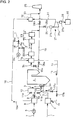
- Fig. 1 is a block diagram showing an embodiment of an apparatus for carrying out the invention in which coal 1 as fuel is pulverized in a mill 2 as fuel supply means into pulverized coal 3 which is supplied to a burner 5a in a wind box 5 on a combustion furnace (boiler) 4.
- Air 7 from a blower 6 is supplied to an air separation unit 8 for separation of the air into oxygen 9 and other nitrogen-prevailing gas 10a, the resultant oxygen 9 being passed through a controller 8a and separated into direct and mixed supply lines 12 and 13 through oxygen flow rate controllers 11a and 11b, respectively, part of the oxygen 9 being directly supplied to the burner 5a, using the direct supply line 12.
- the remainder of the oxygen 9 is mixed in the mixed supply line 13 with part of recirculation gas 15 preheated in and guided from an air preheater 16, which will be detailed later, via recirculating means 14, the gas mixture being supplied as secondary combustion gas to the wind box 5 and thus to a secondary combustion gas supply port of the burner 5a.
- the remainder of the recirculation gas 15 is supplied to the mill 2 for dryness of the coal and as primary combustion gas conveying the pulverized coal 3 to a primary combustion gas supply port of the burner 5a.
- the flow rate of the recirculation gas 15 mixed in the mixed supply line 13 and the flow rate of the recirculation gas 15 guided to the mill 2 are controlled by flow rate controllers 17a and 17b, respectively.
- the pulverized coal 3 and the oxygen 9 as oxidant are burned in the combustion furnace 4 where almost all of carbon content in the coal is converted into carbon dioxide, provided that the primary and secondary combustion gases are supplied with total air ratio of more than 1.
- the coal includes volatile portions such as hydrogen, nitrogen and sulfur, these volatile portions being oxidized by oxygen in the combustion gas to produce acid gases such as NO x and SO x .
- the combustion exhaust gas including the carbon dioxide, the acid gases such as NO x and SO x and powder dust is guided via a flue 19 to the air preheater 16 and then to a dust collector 20 as exhaust gas processing means 23 for removal of dust, a denitration device 21 for removal of NO x and a desulfurization device 22 for removal of SO x .
- the recirculating means 14 Connected to the flue 19 at an outlet of the dust collector 20 is the recirculating means 14 thorough which part of the combustion exhaust gas freed from dust in the dust collector 20 is taken out and supplied to the air preheater 16 via a blower 24, whereby part of the combustion exhaust gas at the outlet of the dust collector 20 is recirculated as recirculation gas 15 by the recirculating means 14 to the burner 5a through the mill 2 and the mixed supply line 13.
- the combustion exhaust gas due to the combustion in the combustion furnace 4 has the carbon dioxide with enhanced concentration whereas the carbon dioxide in the recirculation gas 15 undergoes reduction effect by the combustion in the combustion furnace 4, the concentration of carbon dioxide in the combustion exhaust gas taken out from the combustion furnace 4 being kept to constant higher level.
- the recirculating means 14 Connected to the recirculating means 14 at an inlet of the blower 24 is air intake pipe 18 for intake of air 7.
- the selectors 14a and 18a are changed over such that, by the recirculating means 14, the combustion furnace 4 is fed with the recirculation gas 15 during steady operation of the combustion furnace 4 and with the air 7 during start-up of the combustion furnace 4.
- the remainder of the combustion exhaust gas not recirculated to the recirculating means 14 is guided by the flue 19 to a stack 25.
- the flue 19 is branched by a branching duct 26 to a liquefying unit 27, so that the combustion exhaust gas is selectively guided to the stack 25 and the liquefying unit 27 by changeover of the selectors 28a and 28b.
- the combustion exhaust gas supplied to the liquefying unit 27 is cooled and compressed by a compressor 27a and at least a cooler 27b arranged upstream and/or downstream of the compressor 27a for separation of liquefied carbon dioxide 29, the taken-out liquefied carbon dioxide 29 being stored in a storage container 30.
- the combustion exhaust gas may be cooled and compressed into, for example, 0°C and 7 MPa for taking-out of the liquefied carbon dioxide 29. From the liquefying unit 27, carbon dioxide compressed and not liquefied may be also taken out.
- the other exhaust gas components 31 such as NO x and SO x not liquefied by compression in the liquefying unit 27 are taken out from the liquefying unit 27 to a gas mixer 32.
- the nitrogen-prevailing gas 10a remaining in the separation of the oxygen from the air in the air separation unit 8 has been supplied through a nitrogen gas pipe 10.
- the other exhaust gas components 31 are diluted in the gas mixer 32 with the nitrogen-prevailing gas 10a, diluted exhaust gas 33 in the mixer 32 being guided through the flue 19 to the stack 25.
- the air 7 is supplied as combustion gas to the burner 5a for ordinary air combustion by driving the blower 24.
- the controller 8a at the outlet of the air separation unit 8 being closed not to supply the oxygen 9 to the combustion furnace 4, the selectors 28a and 28b being closed and opened, respectively, so as to guide all of the combustion exhaust gas from the exhaust gas processing means 23 to the stack 25.
- the resultant combustion exhaust gas consists of about 70% of nitrogen, the remainders being carbon dioxide, SO x , steam and the like.
- the selector 18a When absorbed heat by the combustion furnace (boiler) 4 reaches a predetermined value, then the selector 18a is totally closed while the selector 14a is opened.
- part of the combustion exhaust gas treated by at least the dust collector 20 of the exhaust gas processing means 23 is recirculated as recirculation gas 15 via the recirculating means 14 to the mill 2 and mixed supply line 13 by the blower 24.
- the flow rate of the recirculation gas 15 mixed to the mixed supply line 13 and the flow rate of the recirculation gas 15 guided to the mill 2 are controlled by the flow rate controllers 17a and 17b, respectively.
- the oxygen 9 from the preliminarily actuated blower 6 and air separation unit 8 is mixed with the recirculation gas 15 by the mixed supply line 13 to supply the mixture to the wind box 5 and is directly supplied to the burner 5a by the direct supply line 12 for combustion.
- the flow rates of the oxygen 9 guided to the direct supply line 12 and to the mixed supply line 13 are controlled by the oxygen flow rate controllers 11a and 11b, respectively.
- the selectors 28b and 28a are closed and opened, respectively, to guide the combustion exhaust gas from the exhaust gas processing means 23 to the liquefying unit 27 through the branching duct 26.
- the steady operation is started.
- the combustion exhaust gas supplied to the liquefying unit 27 by the branching duct 26 is cooled and compressed into, for example, 0°C and 7 MPa by the cooler 27b and the compressor 27a, whereby the carbon dioxide is liquefied into liquefied carbon dioxide 29 and taken out to the storage container 30.
- the other exhaust gas components 31 such as NO x and SO x not liquefied by the compression by means of the liquefying unit 27 are taken out from the liquefying unit 27 to the gas mixer 32 where they are mixed with the nitrogen-prevailing gas 10a remaining in the separation of the oxygen from the air in the air separation unit 8.
- the other exhaust gas components 31 are guided as diluted exhaust gas 33 diluted with the nitrogen-prevailing gas 10a to the stack 25.
- the combustion exhaust gas with enhanced concentration of carbon dioxide due to the oxygen combustion is compressed in the liquefying unit 27 for separation of the liquefied carbon dioxide. Then, with the carbon dioxide substantially composing the combustion exhaust gas being separated, the other exhaust gas components 31 or NO x and SO x are condensed into enhanced concentration; however, the resultant large volume of nitrogen-prevailing gas 10a is, after the separation of about 21% of oxygen 9 in the air in the air separation unit 8, mixed and diluted with the other exhaust gas components 31, so that it can be discharged via the stack 25 to the atmosphere as diluted gas reliably meeting environmental emission standard.
- the liquefied carbon dioxide 29 taken out to the storage container 30 is directly transported to and isolated and disposed, for example, in an undersea or underground reservoir kept to lower temperature.
- the apparatus can be simplified in construction and the drive energy can be reduced in comparison with a system wherein all of combustion exhaust gas from the combustion furnace 4 is cooled and compressed for taking-out of liquefied carbon dioxide.
- Fig. 2 shows an apparatus wherein a flue 19 for guidance of combustion exhaust gas from a combustion furnace 4 to a stack 25 is connected with a bypass duct 34, exhaust gas processing means 23 and an air preheater 16 being arranged not in the flue 19 but in the bypass duct 34, selector means 35a and 35b being provided for causing the combustion exhaust gas from the combustion furnace 4 to selectively flow to the flue 19 and to the bypass duct 34.
- the operation similar to the steady operation in the above embodiment is conducted with the selector means 35b and 35a being opened and totally closed, respectively, so that all of the combustion exhaust gas from the combustion furnace 4 is caused to flow through the flue 19.
- part of the combustion gas is recirculated as recirculation gas 15 by the recirculating means 14 to the combustion furnace 4 via the air preheater 16, the remaining combustion exhaust gas not recirculated being supplied via the branching duct 26 to the liquefying unit 27 for separation of the liquefied carbon dioxide 29.
- the other exhaust gas components 31 such as NO x and SO x not liquefied by the compression by means of the liquefying unit 27 are guided to the gas mixer 32 where they are mixed with the nitrogen-prevailing gas 10a remaining in the separation of the oxygen from the air in the air separation unit 8, the resultant diluted exhaust gas 33 being guided to and discharged through the stack 25 to the atmosphere.
- the exhaust gas processing means 23 arranged in the bypass duct 34 is used only during the start-up of the combustion equipment, so that the construction of the exhaust gas processing means 23 can be simplified and can be of small-sized. Moreover, during the steady operation, the combustion exhaust gas from the combustion furnace 4 is guided, without being passed through the exhaust gas processing means 23, directly to the liquefying unit 27 to take out the liquefied carbon dioxide 29, and the other remaining exhaust gas components 31 freed from the liquefied carbon dioxide 29 in the liquefying unit 27 can be discharged via the stack 25 to the atmosphere after dilution in the gas mixer 32 with a sufficient volume of nitrogen-prevailing gas 10a. Since the combustion exhaust gas does not pass through the exhaust gas processing means 23, the task of reducing pressure loss can be attained and the exhaust gas processing means 23 can be prolonged in service life.
Landscapes
- Engineering & Computer Science (AREA)
- Chemical & Material Sciences (AREA)
- Mechanical Engineering (AREA)
- General Engineering & Computer Science (AREA)
- Combustion & Propulsion (AREA)
- Chemical Kinetics & Catalysis (AREA)
- Organic Chemistry (AREA)
- Physics & Mathematics (AREA)
- Thermal Sciences (AREA)
- Health & Medical Sciences (AREA)
- Biomedical Technology (AREA)
- Environmental & Geological Engineering (AREA)
- Analytical Chemistry (AREA)
- General Chemical & Material Sciences (AREA)
- Oil, Petroleum & Natural Gas (AREA)
- Inorganic Chemistry (AREA)
- Combustion Of Fluid Fuel (AREA)
- Treating Waste Gases (AREA)
- Air Supply (AREA)
- Chimneys And Flues (AREA)
- Separation By Low-Temperature Treatments (AREA)
Claims (7)
- Verfahren zum Entsorgen von Abgas in einer Verbrennungsanlage, wobei Luft (7) durch eine Lufttrenneinheit (8) in Sauerstoff (9) und in ein anderes vorwiegend Stickstoff enthaltendes Gas (10a) getrennt wird, wobei der Sauerstoff (9), der in der Lufttrenneinheit (8) erhalten wird, und Brennstoff durch einen Brenner (5a) eines Verbrennungsofens (4) verbrannt werden, wobei Verbrennungsabgas von dem Verbrennungsofen (4) wenigstens nach einer Staubentfernungsbehandlung teilweise als Rückführungsgas (15) zu einem Kesselkörper rückgeführt wird, wobei der nicht rückgeführte Rest des Verbrennungsabgases an die Atmosphäre abgegeben wird, wobei das Verfahren das Folgendes umfasst: Komprimieren des nicht rückgeführten Rests des Verbrennungsabgases, der stromabwärts von Abgasbehandlungsmitteln (20, 21, 22, 23) entnommen wird, um verflüssigtes Kohlenstoffdioxid (29) zu entnehmen, Mischen und Verdünnen anderer Abgaskomponenten (31), die ohne Verflüssigung durch Kompression, um eine erhöhte Konzentration zu erhalten, entnommen werden, mit dem anderen vorwiegend Stickstoff enthaltenden Gas (7a), das bei der Trennung des Sauerstoffs (9) von der Luft (7) in der Lufttrenneinheit (8) erzeugt wird, und Abgeben des vermischten und verdünnten Gases an die Atmosphäre.
- Verfahren zum Entsorgen von Abgas in einer Verbrennungsanlage nach Anspruch 1, wobei das verflüssigte Kohlenstoffdioxid (29) durch Kühlen und Komprimieren des nicht rückgeführten Rests des Verbrennungsabgases entnommen wird.
- Verfahren zum Entsorgen von Abgas in einer Verbrennungsanlage nach Anspruch 1, wobei während des Hochfahrens des Verbrennungsofens (4) dem Verbrennungsofen (4) Luft (7) für eine Luftverbrennung des Brennstoffs zugeführt wird, wobei das Verbrennungsabgas vom Verbrennungsofen (4) mit den Abgasbehandlungsmitteln (20, 21, 22, 23) behandelt wird, wobei das Verbrennungsabgas wenigstens nach einer Staubentfernungsbehandlung teilweise zu dem Brenner (5a) rückgeführt wird, wobei der nicht rückgeführte Rest des Verbrennungsabgases an die Atmosphäre abgegeben wird.
- Verfahren zum Entsorgen von Abgas in einer Verbrennungsanlage nach Anspruch 1, wobei das verflüssigte Kohlenstoffdioxid (29), das durch Kühlen und Komprimieren des Verbrennungsabgases entnommen wird, isoliert und entsorgt wird.
- Verfahren zum Entsorgen von Abgas in einer Verbrennungsanlage nach Anspruch 1, wobei der Brennstoff Kohle ist.
- Verfahren zum Entsorgen von Abgas in einer Verbrennungsanlage nach Anspruch 1, wobei die anderen Abgaskomponenten (31) nach der Entnahme des verflüssigten Kohlenstoffdioxids (29) aus dem Verbrennungsabgas NOx und SOx enthalten.
- Vorrichtung zum Entsorgen von Abgas, wobei die Vorrichtung eine Verbrennungsanlage mit Brennstoffzufuhrmitteln (2), einer Lufttrenneinheit (8) zum Trennen von Luft (7) in Sauerstoff und ein vorwiegend Stickstoff enthaltendes Gas (10a), Luftzufuhrmittel (18), einen Verbrennungsofen (4) zum Empfangen von Brennstoff von den Brennstoffzufuhrmitteln (2) und von Sauerstoff (9) von der Lufttrenneinheit (8) oder von Luft (7) von den Luftzufuhrmitteln (18) für eine Verbrennung mit einem Brenner (5a), einen Abzug (19) zum Führen des Verbrennungsabgases in dem Verbrennungsofen (4) zur äußeren Umgebung des Verbrennungsofens (4), Abgasbehandlungsmittel (20, 21, 22, 23) in dem Abzug (19), Rückführungsmittel (14) zum Rückführen eines Teils des Verbrennungsabgases zu dem Brenner (5a), um die Konzentration von Kohlenstoffdioxid in dem Verbrennungsabgas wenigstens nach einer Staubentfernungsbehandlung durch die Abgasbehandlungsmittel (20, 21, 22, 23) zu erhöhen, und einen Schornstein (25) zum Abgeben des nicht durch die Rückführungsmittel (14) rückgeführten Rests des Verbrennungsabgases an die Atmosphäre umfasst, wobei die Vorrichtung eine Verflüssigungseinheit (27), um den nicht rückgeführten Rest des Verbrennungsabgases stromabwärts der Abgasbehandlungsmittel (20, 21, 22, 23) zu empfangen, um ihn zu kühlen und zu komprimieren, um ihn aus dem verflüssigten Kohlenstoffdioxid (29) zu entnehmen, und einen Gasmischer (32) zum Mischen anderer Abgaskomponenten (31), die ohne Verflüssigung durch Kühlung und Kompression in der Verflüssigungseinheit (27) entnommen werden, um die Konzentration zu erhöhen, mit dem vorwiegend Stickstoff enthaltenden Gas (10a), das bei der Trennung des Sauerstoffs (9) von der Luft (7) in der Lufttrenneinheit (8) zurückbleibt, um es als verdünntes Abgas (33) zu dem Schornstein (25) zu führen, umfasst.
Priority Applications (1)
| Application Number | Priority Date | Filing Date | Title |
|---|---|---|---|
| PL06833457T PL1956293T3 (pl) | 2005-11-28 | 2006-11-28 | Urządzenie i sposób odprowadzania gazów spalinowych z układu spalania |
Applications Claiming Priority (2)
| Application Number | Priority Date | Filing Date | Title |
|---|---|---|---|
| JP2005342355A JP2007147161A (ja) | 2005-11-28 | 2005-11-28 | 燃焼装置の排ガス処分方法及び装置 |
| PCT/JP2006/323653 WO2007061107A1 (ja) | 2005-11-28 | 2006-11-28 | 燃焼装置の排ガス処分方法及び装置 |
Publications (3)
| Publication Number | Publication Date |
|---|---|
| EP1956293A1 EP1956293A1 (de) | 2008-08-13 |
| EP1956293A4 EP1956293A4 (de) | 2009-12-09 |
| EP1956293B1 true EP1956293B1 (de) | 2019-08-28 |
Family
ID=38067327
Family Applications (1)
| Application Number | Title | Priority Date | Filing Date |
|---|---|---|---|
| EP06833457.2A Active EP1956293B1 (de) | 2005-11-28 | 2006-11-28 | Verfahren und einrichtung zum entfernen von abgas aus einem verbrennungssystem |
Country Status (9)
| Country | Link |
|---|---|
| US (1) | US20090031933A1 (de) |
| EP (1) | EP1956293B1 (de) |
| JP (1) | JP2007147161A (de) |
| KR (1) | KR20080075848A (de) |
| CN (1) | CN101336353A (de) |
| AU (1) | AU2006316952B2 (de) |
| ES (1) | ES2758715T3 (de) |
| PL (1) | PL1956293T3 (de) |
| WO (1) | WO2007061107A1 (de) |
Families Citing this family (54)
| Publication number | Priority date | Publication date | Assignee | Title |
|---|---|---|---|---|
| DE102004061400B4 (de) * | 2004-12-21 | 2012-12-20 | Umicore Ag & Co. Kg | Verfahren zur Erzeugung eines Stromes heißer Verbrennungsabgase mit einstellbarer Temperatur, Apparatur zur Durchführung des Verfahrens und Verwendung der Verbrennungsabgase zur gezielten Alterung von Katalysatoren |
| US7708804B2 (en) * | 2007-07-11 | 2010-05-04 | L'air Liquide, Societe Anonyme Pour L'etude Et L'exploitation Des Procedes Georges Claude | Process and apparatus for the separation of a gaseous mixture |
| PL2209920T3 (pl) * | 2007-11-01 | 2017-01-31 | Self-Screen B V | Nowy sposób wykrywania hpv szyjki macicy |
| FR2924203B1 (fr) * | 2007-11-26 | 2010-04-02 | Air Liquide | Adaptation d'une centrale a oxycombustion a la disponibilite de l'energie et a la quantite de co2 a capturer |
| JP4909296B2 (ja) * | 2008-02-12 | 2012-04-04 | 三菱重工業株式会社 | 重質燃料焚ボイラシステム及びその運転方法 |
| JP5138028B2 (ja) * | 2008-03-06 | 2013-02-06 | 株式会社Ihi | 酸素燃焼ボイラの酸素供給制御方法及び装置 |
| CN102047040B (zh) * | 2008-03-06 | 2013-03-13 | 株式会社Ihi | 氧燃烧锅炉的一次再循环废气流量控制方法及装置 |
| JP5094959B2 (ja) * | 2008-03-06 | 2012-12-12 | 株式会社Ihi | 酸素燃焼ボイラの二酸化炭素供給方法及び二酸化炭素供給設備 |
| KR101249713B1 (ko) * | 2008-03-06 | 2013-04-05 | 일렉트릭 파워 디벨롭먼트 컴퍼니 리미티드 | 산소 연소 보일러의 연소 제어 방법 및 장치 |
| PL2251599T3 (pl) * | 2008-03-06 | 2015-05-29 | Ihi Corp | Sposób oraz urządzenie do regulowania gazów spalinowych w kotle opalanym mieszanką tlenowo-paliwową |
| PL2267368T3 (pl) * | 2008-03-06 | 2017-05-31 | Ihi Corporation | Kocioł do spalania tlenowego |
| ES2420558T3 (es) * | 2008-03-06 | 2013-08-23 | Ihi Corporation | Metodo y aparato de control del suministro de oxígeno en una caldera |
| JP4644725B2 (ja) * | 2008-05-07 | 2011-03-02 | 株式会社日立製作所 | 酸素燃焼ボイラシステム,微粉炭燃焼ボイラの改造方法,酸素燃焼ボイラシステムの制御装置及びその制御方法 |
| US20090320725A1 (en) * | 2008-06-25 | 2009-12-31 | Alstom Technology Ltd. | Furnace system with internal flue gas recirculation |
| JP5183372B2 (ja) * | 2008-08-29 | 2013-04-17 | 株式会社日立製作所 | 酸素燃焼ボイラシステム及び燃焼方法 |
| JP4920051B2 (ja) * | 2009-02-25 | 2012-04-18 | 株式会社日立製作所 | 酸素燃焼ボイラプラント及び酸素燃焼ボイラプラントの運転方法 |
| US20120085339A1 (en) * | 2009-03-26 | 2012-04-12 | Fadi Eldabbagh | System to Lower Emissions and Improve Energy Efficiency on Fossil Fuels and Bio-Fuels Combustion Systems |
| KR101129409B1 (ko) * | 2009-09-30 | 2012-03-27 | 한국전력공사 | 공기와 순산소 겸용 미분탄 연소 보일러 시스템 |
| JP5350996B2 (ja) | 2009-11-25 | 2013-11-27 | バブコック日立株式会社 | 酸素燃焼システムの排ガス処理装置 |
| US20110139046A1 (en) * | 2009-12-16 | 2011-06-16 | Foster Wheeler Energy Corporation | Emissionless Oxyfuel Combustion Process and a Combustion System Using Such a Process |
| FR2956592A1 (fr) * | 2010-02-23 | 2011-08-26 | Air Liquide | Procede de traitement des fumees issues d'une combustion |
| EP2551588B1 (de) | 2010-03-24 | 2019-01-30 | IHI Corporation | Brennervorrichtung |
| JP5050071B2 (ja) * | 2010-03-29 | 2012-10-17 | 株式会社日立製作所 | ボイラ装置 |
| CA2809655A1 (en) | 2010-05-18 | 2011-11-24 | Babcock-Hitachi Kabushiki Kaisha | Flue gas desulfurization device, combustion system, and combustion method |
| JP5535782B2 (ja) * | 2010-06-16 | 2014-07-02 | 三菱重工業株式会社 | 燃焼システム |
| JP5427741B2 (ja) * | 2010-09-21 | 2014-02-26 | 株式会社日立製作所 | 多目的火力発電システム |
| JP2012093002A (ja) * | 2010-10-25 | 2012-05-17 | Babcock Hitachi Kk | ボイラシステム及びボイラシステムの運用方法 |
| DE102011002612A1 (de) * | 2011-01-13 | 2012-07-19 | Siemens Aktiengesellschaft | Verfahren zur Behandlung eines kohlendioxidhaltigen Abgases |
| EP2487439B1 (de) * | 2011-02-14 | 2019-05-08 | General Electric Technology GmbH | Verfahren und System zum Mahlen eines Brennstoffes für einen Brenner zur Sauerstoff-Brennstoff-Verbrennung |
| US20120222591A1 (en) * | 2011-03-04 | 2012-09-06 | Foster Wheeler North America Corp. | Method of and Apparatus for Selective Catalytic NOx Reduction in a Power Boiler |
| US20130152595A1 (en) * | 2011-12-20 | 2013-06-20 | Alexander Alekseev | Process for the enhancement of power plant with co2 capture and system for realization of the process |
| US8753108B2 (en) * | 2012-03-30 | 2014-06-17 | Alstom Technology Ltd | Method and apparatus for treatment of unburnts |
| EP2706298B1 (de) * | 2012-09-05 | 2017-12-20 | L'air Liquide, Societe Anonyme Pour L'etude Et L'exploitation Des Procedes Georges Claude | Verfahren zur Bereitstellung von Brennstoff und Luft und/oder eines sauerstoffreichen Gases an mindestens zwei Einheiten, die sauerstoffreiches Gas verbrauchen |
| US9482127B2 (en) | 2012-09-11 | 2016-11-01 | General Electric Technology Gmbh | Booster air heater for high moisture fuels |
| CN105050688B (zh) * | 2012-12-31 | 2017-03-15 | 英温提斯热力技术有限公司 | 用于从燃烧气体中集成式分离二氧化碳气体的系统和方法 |
| CA2898519C (en) * | 2013-01-30 | 2018-10-16 | Bogdan Wojak | Sulphur-assisted carbon capture and storage (ccs) processes and systems |
| CN103196136B (zh) * | 2013-04-27 | 2015-09-09 | 东南大学 | 一种富氧燃烧热量梯级利用的方法及装置 |
| US9939153B2 (en) * | 2013-06-03 | 2018-04-10 | Washington University | Method and apparatus for capturing carbon dioxide during combustion of carbon containing fuel |
| PL2942494T3 (pl) * | 2014-05-08 | 2020-03-31 | General Electric Technology Gmbh | Instalacja opalana mieszanką tlenowo-węglową z integracją ciepła |
| TW201617126A (zh) * | 2014-08-22 | 2016-05-16 | 卡本克林解決方案有限公司 | 含有醇類及胺類之碳捕捉溶劑以及使用此溶劑之方法 |
| JP6471485B2 (ja) * | 2014-12-16 | 2019-02-20 | 株式会社Ihi | 酸素燃焼ボイラ設備の脱塵装置入口温度制御方法及び装置 |
| DE102015108014B3 (de) * | 2015-05-20 | 2016-11-24 | Chemisch Thermische Prozesstechnik Gmbh | Verfahren und Anlage zur Reinigung von mit Stickoxiden beladenen Abgasen |
| CN105066113A (zh) * | 2015-07-27 | 2015-11-18 | 四川川锅锅炉有限责任公司 | 煤粉炉富氧燃烧烟气近零排放发电系统 |
| CN105042575A (zh) * | 2015-07-27 | 2015-11-11 | 四川川锅锅炉有限责任公司 | 燃油、燃气锅炉富氧燃烧烟气近零排放发电系统 |
| US9919268B2 (en) * | 2015-10-21 | 2018-03-20 | 8 Rivers Capital, Llc | Systems and methods for removing combustion products from a power generation cycle |
| WO2017147681A1 (en) | 2016-03-04 | 2017-09-08 | Bogdan Wojak | Sulphur-assisted carbon capture and utilization (ccu) methods and systems |
| CN105840260A (zh) * | 2016-03-24 | 2016-08-10 | 华中科技大学 | 一种锅炉梯级用能系统及方法 |
| CN105889947A (zh) * | 2016-05-30 | 2016-08-24 | 广东上典环境保护工程有限公司 | 一种新型锅炉无硝燃烧系统 |
| CN105889969A (zh) * | 2016-05-30 | 2016-08-24 | 广东上典环境保护工程有限公司 | 一种可对二氧化碳进行回收的无硝燃烧系统 |
| KR102059191B1 (ko) * | 2018-01-30 | 2019-12-24 | 두산중공업 주식회사 | 습식배연 탈황장치 및 이를 포함하는 배연처리 시스템 |
| CN109838684A (zh) * | 2019-01-25 | 2019-06-04 | 集美大学 | 水下航器废气的使用和储存装置及其方法 |
| JP7242774B2 (ja) * | 2021-07-26 | 2023-03-20 | 株式会社タクマ | 排ガス処理設備、及び排ガス処理方法 |
| CN113797700A (zh) * | 2021-09-22 | 2021-12-17 | 乔治洛德方法研究和开发液化空气有限公司 | 分离空气以及产生富二氧化碳产品的集成单元及方法 |
| EP4639028A1 (de) * | 2022-12-20 | 2025-10-29 | SABIC Global Technologies B.V. | Systeme für oxyfuel-verbrennungsöfen mit wärmerückgewinnung und reduzierter rückführung von rauchgas |
Family Cites Families (21)
| Publication number | Priority date | Publication date | Assignee | Title |
|---|---|---|---|---|
| JPS5236610B2 (de) * | 1974-05-09 | 1977-09-17 | ||
| JPH04244504A (ja) * | 1991-01-30 | 1992-09-01 | Central Res Inst Of Electric Power Ind | 二酸化炭素回収型石炭火力発電システム |
| JP3068888B2 (ja) * | 1991-05-28 | 2000-07-24 | 株式会社日立製作所 | 燃焼装置及びその運転方法 |
| JP3053914B2 (ja) * | 1991-07-16 | 2000-06-19 | バブコック日立株式会社 | Co2回収型ボイラ |
| JPH0526428A (ja) * | 1991-07-23 | 1993-02-02 | Kubota Corp | 廃棄物燃焼排ガス中のco2 回収方法 |
| JPH06293888A (ja) * | 1993-04-09 | 1994-10-21 | Babcock Hitachi Kk | 石炭ガス化プラントの硫黄回収方法及び装置 |
| US5406786A (en) * | 1993-07-16 | 1995-04-18 | Air Products And Chemicals, Inc. | Integrated air separation - gas turbine electrical generation process |
| JP3338555B2 (ja) * | 1994-05-24 | 2002-10-28 | 電源開発株式会社 | 二酸化炭素回収型排ガス再循環ボイラ設備の燃焼バーナ |
| US5906806A (en) * | 1996-10-16 | 1999-05-25 | Clark; Steve L. | Reduced emission combustion process with resource conservation and recovery options "ZEROS" zero-emission energy recycling oxidation system |
| JP3700073B2 (ja) * | 1997-11-18 | 2005-09-28 | バブコック日立株式会社 | 硫化水素含有ガスの燃焼方法及び装置 |
| JP3309387B2 (ja) * | 1997-11-28 | 2002-07-29 | 日本鋼管株式会社 | 廃棄物焼却炉 |
| US6401633B2 (en) * | 1998-04-06 | 2002-06-11 | Minergy Corporation | Closed cycle waste combustion |
| US6029588A (en) * | 1998-04-06 | 2000-02-29 | Minergy Corp. | Closed cycle waste combustion |
| US6314896B1 (en) * | 1999-06-10 | 2001-11-13 | L'air Liquide, Societe Anonyme Pour L'etude Et L'exploitation Des Procedes Georges Claude | Method for operating a boiler using oxygen-enriched oxidants |
| US6574962B1 (en) * | 2001-11-23 | 2003-06-10 | Justin Chin-Chung Hsu | KOH flue gas recirculation power plant with waste heat and byproduct recovery |
| US6505567B1 (en) * | 2001-11-26 | 2003-01-14 | Alstom (Switzerland) Ltd | Oxygen fired circulating fluidized bed steam generator |
| US6935251B2 (en) * | 2002-02-15 | 2005-08-30 | American Air Liquide, Inc. | Steam-generating combustion system and method for emission control using oxygen enhancement |
| WO2004042276A2 (en) * | 2002-10-30 | 2004-05-21 | Krebs & Sisler Lp | A method and apparatus to conduct oxygen-enriched combustion |
| US6886944B2 (en) * | 2003-05-13 | 2005-05-03 | Hewlett-Packard Development Company, L.P. | Projector brightness enhancement using rectilinear apertures |
| US6843185B1 (en) * | 2003-06-27 | 2005-01-18 | Maxon Corporation | Burner with oxygen and fuel mixing apparatus |
| US20070144415A1 (en) * | 2005-11-29 | 2007-06-28 | Varagani Rajani K | Coal Upgrading Process Utilizing Nitrogen and/or Carbon Dioxide |
-
2005
- 2005-11-28 JP JP2005342355A patent/JP2007147161A/ja active Pending
-
2006
- 2006-11-28 PL PL06833457T patent/PL1956293T3/pl unknown
- 2006-11-28 US US12/094,789 patent/US20090031933A1/en not_active Abandoned
- 2006-11-28 WO PCT/JP2006/323653 patent/WO2007061107A1/ja not_active Ceased
- 2006-11-28 ES ES06833457T patent/ES2758715T3/es active Active
- 2006-11-28 KR KR1020087012667A patent/KR20080075848A/ko not_active Ceased
- 2006-11-28 AU AU2006316952A patent/AU2006316952B2/en active Active
- 2006-11-28 CN CNA2006800517238A patent/CN101336353A/zh active Pending
- 2006-11-28 EP EP06833457.2A patent/EP1956293B1/de active Active
Non-Patent Citations (1)
| Title |
|---|
| None * |
Also Published As
| Publication number | Publication date |
|---|---|
| ES2758715T3 (es) | 2020-05-06 |
| EP1956293A4 (de) | 2009-12-09 |
| AU2006316952B2 (en) | 2010-11-25 |
| US20090031933A1 (en) | 2009-02-05 |
| WO2007061107A1 (ja) | 2007-05-31 |
| PL1956293T3 (pl) | 2020-02-28 |
| CN101336353A (zh) | 2008-12-31 |
| KR20080075848A (ko) | 2008-08-19 |
| AU2006316952A1 (en) | 2007-05-31 |
| EP1956293A1 (de) | 2008-08-13 |
| JP2007147161A (ja) | 2007-06-14 |
Similar Documents
| Publication | Publication Date | Title |
|---|---|---|
| AU2006316952B2 (en) | Disposal method and equipment for exhaust gas from combustion system | |
| EP1959193B1 (de) | Verfahren und vorrichtung zur steuerung von verbrennung in mit sauerstoff befeuerten kesseln | |
| EP2182279B1 (de) | Oxyfuel-Kesselsystem und Steuerungsverfahren dafür | |
| JP6348416B2 (ja) | 低エミッションタービンシステムにおいて化学量論的燃焼を制御するシステム及び方法 | |
| EP2368022B1 (de) | Kraftwerk mit co2-abscheidung | |
| EP2261558B1 (de) | Verfahren zur steuerung von abgas in einem kessel zur verbrennung von sauerstoff und vorrichtung dafür | |
| JP4981771B2 (ja) | 石炭ガス化複合発電設備 | |
| JP3068888B2 (ja) | 燃焼装置及びその運転方法 | |
| EP2267367B1 (de) | Verfahren und vorrichtung zur steuerung der sauerstoffzufuhr in einem sauerstoff-brennstoff-verbrennungskessel | |
| EP2116765A2 (de) | Oxyfuel-Kessel und Verfahren zum Nachrüsten eines luftbefeuerten Kessels | |
| US20100180565A1 (en) | Methods for increasing carbon dioxide content in gas turbine exhaust and systems for achieving the same | |
| US7805923B2 (en) | Integrated coal gasification combined cycle plant | |
| WO2012035777A1 (ja) | 燃焼プラント | |
| JP2011141075A (ja) | 酸素燃焼発電プラントとその運転方法 | |
| US7810310B2 (en) | Integrated coal gasification combined cycle plant | |
| EP2629009A1 (de) | Kesselbrennsystem und betriebsverfahren dafür | |
| US20070281255A1 (en) | Process and device for feeding oxidizing agent into a combustion system | |
| EP2530278A1 (de) | Anordnung und Verfahren zur Abgasrückführung | |
| CN119178147B (zh) | 一种油田火驱采出气资源化处理系统 |
Legal Events
| Date | Code | Title | Description |
|---|---|---|---|
| PUAI | Public reference made under article 153(3) epc to a published international application that has entered the european phase |
Free format text: ORIGINAL CODE: 0009012 |
|
| 17P | Request for examination filed |
Effective date: 20080528 |
|
| AK | Designated contracting states |
Kind code of ref document: A1 Designated state(s): AT BE BG CH CY CZ DE DK EE ES FI FR GB GR HU IE IS IT LI LT LU LV MC NL PL PT RO SE SI SK TR |
|
| A4 | Supplementary search report drawn up and despatched |
Effective date: 20091111 |
|
| DAX | Request for extension of the european patent (deleted) | ||
| 17Q | First examination report despatched |
Effective date: 20150731 |
|
| GRAP | Despatch of communication of intention to grant a patent |
Free format text: ORIGINAL CODE: EPIDOSNIGR1 |
|
| STAA | Information on the status of an ep patent application or granted ep patent |
Free format text: STATUS: GRANT OF PATENT IS INTENDED |
|
| TPAC | Observations filed by third parties |
Free format text: ORIGINAL CODE: EPIDOSNTIPA |
|
| INTG | Intention to grant announced |
Effective date: 20190318 |
|
| GRAS | Grant fee paid |
Free format text: ORIGINAL CODE: EPIDOSNIGR3 |
|
| GRAA | (expected) grant |
Free format text: ORIGINAL CODE: 0009210 |
|
| STAA | Information on the status of an ep patent application or granted ep patent |
Free format text: STATUS: THE PATENT HAS BEEN GRANTED |
|
| AK | Designated contracting states |
Kind code of ref document: B1 Designated state(s): AT BE BG CH CY CZ DE DK EE ES FI FR GB GR HU IE IS IT LI LT LU LV MC NL PL PT RO SE SI SK TR |
|
| REG | Reference to a national code |
Ref country code: GB Ref legal event code: FG4D |
|
| REG | Reference to a national code |
Ref country code: CH Ref legal event code: EP |
|
| REG | Reference to a national code |
Ref country code: AT Ref legal event code: REF Ref document number: 1172866 Country of ref document: AT Kind code of ref document: T Effective date: 20190915 |
|
| REG | Reference to a national code |
Ref country code: IE Ref legal event code: FG4D |
|
| REG | Reference to a national code |
Ref country code: DE Ref legal event code: R096 Ref document number: 602006058526 Country of ref document: DE |
|
| REG | Reference to a national code |
Ref country code: NL Ref legal event code: MP Effective date: 20190828 |
|
| REG | Reference to a national code |
Ref country code: LT Ref legal event code: MG4D |
|
| PG25 | Lapsed in a contracting state [announced via postgrant information from national office to epo] |
Ref country code: NL Free format text: LAPSE BECAUSE OF FAILURE TO SUBMIT A TRANSLATION OF THE DESCRIPTION OR TO PAY THE FEE WITHIN THE PRESCRIBED TIME-LIMIT Effective date: 20190828 Ref country code: BG Free format text: LAPSE BECAUSE OF FAILURE TO SUBMIT A TRANSLATION OF THE DESCRIPTION OR TO PAY THE FEE WITHIN THE PRESCRIBED TIME-LIMIT Effective date: 20191128 Ref country code: SE Free format text: LAPSE BECAUSE OF FAILURE TO SUBMIT A TRANSLATION OF THE DESCRIPTION OR TO PAY THE FEE WITHIN THE PRESCRIBED TIME-LIMIT Effective date: 20190828 Ref country code: LT Free format text: LAPSE BECAUSE OF FAILURE TO SUBMIT A TRANSLATION OF THE DESCRIPTION OR TO PAY THE FEE WITHIN THE PRESCRIBED TIME-LIMIT Effective date: 20190828 Ref country code: PT Free format text: LAPSE BECAUSE OF FAILURE TO SUBMIT A TRANSLATION OF THE DESCRIPTION OR TO PAY THE FEE WITHIN THE PRESCRIBED TIME-LIMIT Effective date: 20191230 Ref country code: FI Free format text: LAPSE BECAUSE OF FAILURE TO SUBMIT A TRANSLATION OF THE DESCRIPTION OR TO PAY THE FEE WITHIN THE PRESCRIBED TIME-LIMIT Effective date: 20190828 |
|
| PG25 | Lapsed in a contracting state [announced via postgrant information from national office to epo] |
Ref country code: LV Free format text: LAPSE BECAUSE OF FAILURE TO SUBMIT A TRANSLATION OF THE DESCRIPTION OR TO PAY THE FEE WITHIN THE PRESCRIBED TIME-LIMIT Effective date: 20190828 Ref country code: IS Free format text: LAPSE BECAUSE OF FAILURE TO SUBMIT A TRANSLATION OF THE DESCRIPTION OR TO PAY THE FEE WITHIN THE PRESCRIBED TIME-LIMIT Effective date: 20191228 Ref country code: GR Free format text: LAPSE BECAUSE OF FAILURE TO SUBMIT A TRANSLATION OF THE DESCRIPTION OR TO PAY THE FEE WITHIN THE PRESCRIBED TIME-LIMIT Effective date: 20191129 |
|
| REG | Reference to a national code |
Ref country code: AT Ref legal event code: MK05 Ref document number: 1172866 Country of ref document: AT Kind code of ref document: T Effective date: 20190828 |
|
| PG25 | Lapsed in a contracting state [announced via postgrant information from national office to epo] |
Ref country code: TR Free format text: LAPSE BECAUSE OF FAILURE TO SUBMIT A TRANSLATION OF THE DESCRIPTION OR TO PAY THE FEE WITHIN THE PRESCRIBED TIME-LIMIT Effective date: 20190828 |
|
| PG25 | Lapsed in a contracting state [announced via postgrant information from national office to epo] |
Ref country code: AT Free format text: LAPSE BECAUSE OF FAILURE TO SUBMIT A TRANSLATION OF THE DESCRIPTION OR TO PAY THE FEE WITHIN THE PRESCRIBED TIME-LIMIT Effective date: 20190828 Ref country code: DK Free format text: LAPSE BECAUSE OF FAILURE TO SUBMIT A TRANSLATION OF THE DESCRIPTION OR TO PAY THE FEE WITHIN THE PRESCRIBED TIME-LIMIT Effective date: 20190828 Ref country code: EE Free format text: LAPSE BECAUSE OF FAILURE TO SUBMIT A TRANSLATION OF THE DESCRIPTION OR TO PAY THE FEE WITHIN THE PRESCRIBED TIME-LIMIT Effective date: 20190828 Ref country code: RO Free format text: LAPSE BECAUSE OF FAILURE TO SUBMIT A TRANSLATION OF THE DESCRIPTION OR TO PAY THE FEE WITHIN THE PRESCRIBED TIME-LIMIT Effective date: 20190828 |
|
| REG | Reference to a national code |
Ref country code: ES Ref legal event code: FG2A Ref document number: 2758715 Country of ref document: ES Kind code of ref document: T3 Effective date: 20200506 |
|
| PG25 | Lapsed in a contracting state [announced via postgrant information from national office to epo] |
Ref country code: IS Free format text: LAPSE BECAUSE OF FAILURE TO SUBMIT A TRANSLATION OF THE DESCRIPTION OR TO PAY THE FEE WITHIN THE PRESCRIBED TIME-LIMIT Effective date: 20200224 Ref country code: CZ Free format text: LAPSE BECAUSE OF FAILURE TO SUBMIT A TRANSLATION OF THE DESCRIPTION OR TO PAY THE FEE WITHIN THE PRESCRIBED TIME-LIMIT Effective date: 20190828 Ref country code: SK Free format text: LAPSE BECAUSE OF FAILURE TO SUBMIT A TRANSLATION OF THE DESCRIPTION OR TO PAY THE FEE WITHIN THE PRESCRIBED TIME-LIMIT Effective date: 20190828 |
|
| REG | Reference to a national code |
Ref country code: DE Ref legal event code: R097 Ref document number: 602006058526 Country of ref document: DE |
|
| REG | Reference to a national code |
Ref country code: CH Ref legal event code: PL |
|
| PLBE | No opposition filed within time limit |
Free format text: ORIGINAL CODE: 0009261 |
|
| STAA | Information on the status of an ep patent application or granted ep patent |
Free format text: STATUS: NO OPPOSITION FILED WITHIN TIME LIMIT |
|
| PG2D | Information on lapse in contracting state deleted |
Ref country code: IS |
|
| PG25 | Lapsed in a contracting state [announced via postgrant information from national office to epo] |
Ref country code: CH Free format text: LAPSE BECAUSE OF NON-PAYMENT OF DUE FEES Effective date: 20191130 Ref country code: LI Free format text: LAPSE BECAUSE OF NON-PAYMENT OF DUE FEES Effective date: 20191130 Ref country code: LU Free format text: LAPSE BECAUSE OF NON-PAYMENT OF DUE FEES Effective date: 20191128 Ref country code: MC Free format text: LAPSE BECAUSE OF FAILURE TO SUBMIT A TRANSLATION OF THE DESCRIPTION OR TO PAY THE FEE WITHIN THE PRESCRIBED TIME-LIMIT Effective date: 20190828 |
|
| 26N | No opposition filed |
Effective date: 20200603 |
|
| REG | Reference to a national code |
Ref country code: BE Ref legal event code: MM Effective date: 20191130 |
|
| PG25 | Lapsed in a contracting state [announced via postgrant information from national office to epo] |
Ref country code: SI Free format text: LAPSE BECAUSE OF FAILURE TO SUBMIT A TRANSLATION OF THE DESCRIPTION OR TO PAY THE FEE WITHIN THE PRESCRIBED TIME-LIMIT Effective date: 20190828 |
|
| PG25 | Lapsed in a contracting state [announced via postgrant information from national office to epo] |
Ref country code: IE Free format text: LAPSE BECAUSE OF NON-PAYMENT OF DUE FEES Effective date: 20191128 |
|
| PG25 | Lapsed in a contracting state [announced via postgrant information from national office to epo] |
Ref country code: BE Free format text: LAPSE BECAUSE OF NON-PAYMENT OF DUE FEES Effective date: 20191130 |
|
| PG25 | Lapsed in a contracting state [announced via postgrant information from national office to epo] |
Ref country code: CY Free format text: LAPSE BECAUSE OF FAILURE TO SUBMIT A TRANSLATION OF THE DESCRIPTION OR TO PAY THE FEE WITHIN THE PRESCRIBED TIME-LIMIT Effective date: 20190828 |
|
| PG25 | Lapsed in a contracting state [announced via postgrant information from national office to epo] |
Ref country code: HU Free format text: LAPSE BECAUSE OF FAILURE TO SUBMIT A TRANSLATION OF THE DESCRIPTION OR TO PAY THE FEE WITHIN THE PRESCRIBED TIME-LIMIT; INVALID AB INITIO Effective date: 20061128 |
|
| PGFP | Annual fee paid to national office [announced via postgrant information from national office to epo] |
Ref country code: FR Payment date: 20250930 Year of fee payment: 20 |
|
| PGFP | Annual fee paid to national office [announced via postgrant information from national office to epo] |
Ref country code: DE Payment date: 20250930 Year of fee payment: 20 |
|
| PGFP | Annual fee paid to national office [announced via postgrant information from national office to epo] |
Ref country code: GB Payment date: 20251001 Year of fee payment: 20 |
|
| PGFP | Annual fee paid to national office [announced via postgrant information from national office to epo] |
Ref country code: IT Payment date: 20251022 Year of fee payment: 20 |
|
| PGFP | Annual fee paid to national office [announced via postgrant information from national office to epo] |
Ref country code: PL Payment date: 20251013 Year of fee payment: 20 |
|
| PGFP | Annual fee paid to national office [announced via postgrant information from national office to epo] |
Ref country code: ES Payment date: 20251209 Year of fee payment: 20 |