EP1947711A2 - Dreidimensionale Batterie und ihre Elektrodenstruktur sowie Verfahren zur Herstellung von Elektrodenmaterial von dreidimensionalen Batterien - Google Patents
Dreidimensionale Batterie und ihre Elektrodenstruktur sowie Verfahren zur Herstellung von Elektrodenmaterial von dreidimensionalen Batterien Download PDFInfo
- Publication number
- EP1947711A2 EP1947711A2 EP08006222A EP08006222A EP1947711A2 EP 1947711 A2 EP1947711 A2 EP 1947711A2 EP 08006222 A EP08006222 A EP 08006222A EP 08006222 A EP08006222 A EP 08006222A EP 1947711 A2 EP1947711 A2 EP 1947711A2
- Authority
- EP
- European Patent Office
- Prior art keywords
- nickel
- current collector
- active material
- plated
- cathode
- Prior art date
- Legal status (The legal status is an assumption and is not a legal conclusion. Google has not performed a legal analysis and makes no representation as to the accuracy of the status listed.)
- Granted
Links
Images


Classifications
-
- H—ELECTRICITY
- H01—ELECTRIC ELEMENTS
- H01M—PROCESSES OR MEANS, e.g. BATTERIES, FOR THE DIRECT CONVERSION OF CHEMICAL ENERGY INTO ELECTRICAL ENERGY
- H01M10/00—Secondary cells; Manufacture thereof
- H01M10/24—Alkaline accumulators
- H01M10/30—Nickel accumulators
-
- H—ELECTRICITY
- H01—ELECTRIC ELEMENTS
- H01M—PROCESSES OR MEANS, e.g. BATTERIES, FOR THE DIRECT CONVERSION OF CHEMICAL ENERGY INTO ELECTRICAL ENERGY
- H01M10/00—Secondary cells; Manufacture thereof
- H01M10/24—Alkaline accumulators
- H01M10/28—Construction or manufacture
-
- H—ELECTRICITY
- H01—ELECTRIC ELEMENTS
- H01M—PROCESSES OR MEANS, e.g. BATTERIES, FOR THE DIRECT CONVERSION OF CHEMICAL ENERGY INTO ELECTRICAL ENERGY
- H01M10/00—Secondary cells; Manufacture thereof
- H01M10/04—Construction or manufacture in general
- H01M10/0413—Large-sized flat cells or batteries for motive or stationary systems with plate-like electrodes
-
- H—ELECTRICITY
- H01—ELECTRIC ELEMENTS
- H01M—PROCESSES OR MEANS, e.g. BATTERIES, FOR THE DIRECT CONVERSION OF CHEMICAL ENERGY INTO ELECTRICAL ENERGY
- H01M10/00—Secondary cells; Manufacture thereof
- H01M10/04—Construction or manufacture in general
- H01M10/0459—Cells or batteries with folded separator between plate-like electrodes
-
- H—ELECTRICITY
- H01—ELECTRIC ELEMENTS
- H01M—PROCESSES OR MEANS, e.g. BATTERIES, FOR THE DIRECT CONVERSION OF CHEMICAL ENERGY INTO ELECTRICAL ENERGY
- H01M10/00—Secondary cells; Manufacture thereof
- H01M10/24—Alkaline accumulators
- H01M10/26—Selection of materials as electrolytes
-
- H—ELECTRICITY
- H01—ELECTRIC ELEMENTS
- H01M—PROCESSES OR MEANS, e.g. BATTERIES, FOR THE DIRECT CONVERSION OF CHEMICAL ENERGY INTO ELECTRICAL ENERGY
- H01M4/00—Electrodes
- H01M4/02—Electrodes composed of, or comprising, active material
- H01M4/24—Electrodes for alkaline accumulators
-
- H—ELECTRICITY
- H01—ELECTRIC ELEMENTS
- H01M—PROCESSES OR MEANS, e.g. BATTERIES, FOR THE DIRECT CONVERSION OF CHEMICAL ENERGY INTO ELECTRICAL ENERGY
- H01M4/00—Electrodes
- H01M4/02—Electrodes composed of, or comprising, active material
- H01M4/24—Electrodes for alkaline accumulators
- H01M4/26—Processes of manufacture
-
- H—ELECTRICITY
- H01—ELECTRIC ELEMENTS
- H01M—PROCESSES OR MEANS, e.g. BATTERIES, FOR THE DIRECT CONVERSION OF CHEMICAL ENERGY INTO ELECTRICAL ENERGY
- H01M4/00—Electrodes
- H01M4/02—Electrodes composed of, or comprising, active material
- H01M4/24—Electrodes for alkaline accumulators
- H01M4/32—Nickel oxide or hydroxide electrodes
-
- H—ELECTRICITY
- H01—ELECTRIC ELEMENTS
- H01M—PROCESSES OR MEANS, e.g. BATTERIES, FOR THE DIRECT CONVERSION OF CHEMICAL ENERGY INTO ELECTRICAL ENERGY
- H01M4/00—Electrodes
- H01M4/02—Electrodes composed of, or comprising, active material
- H01M4/64—Carriers or collectors
- H01M4/66—Selection of materials
-
- H—ELECTRICITY
- H01—ELECTRIC ELEMENTS
- H01M—PROCESSES OR MEANS, e.g. BATTERIES, FOR THE DIRECT CONVERSION OF CHEMICAL ENERGY INTO ELECTRICAL ENERGY
- H01M4/00—Electrodes
- H01M4/02—Electrodes composed of, or comprising, active material
- H01M4/64—Carriers or collectors
- H01M4/70—Carriers or collectors characterised by shape or form
- H01M4/76—Containers for holding the active material, e.g. tubes, capsules
- H01M4/762—Porous or perforated metallic containers
-
- H—ELECTRICITY
- H01—ELECTRIC ELEMENTS
- H01M—PROCESSES OR MEANS, e.g. BATTERIES, FOR THE DIRECT CONVERSION OF CHEMICAL ENERGY INTO ELECTRICAL ENERGY
- H01M50/00—Constructional details or processes of manufacture of the non-active parts of electrochemical cells other than fuel cells, e.g. hybrid cells
- H01M50/40—Separators; Membranes; Diaphragms; Spacing elements inside cells
- H01M50/409—Separators, membranes or diaphragms characterised by the material
- H01M50/443—Particulate material
-
- H—ELECTRICITY
- H01—ELECTRIC ELEMENTS
- H01M—PROCESSES OR MEANS, e.g. BATTERIES, FOR THE DIRECT CONVERSION OF CHEMICAL ENERGY INTO ELECTRICAL ENERGY
- H01M50/00—Constructional details or processes of manufacture of the non-active parts of electrochemical cells other than fuel cells, e.g. hybrid cells
- H01M50/40—Separators; Membranes; Diaphragms; Spacing elements inside cells
- H01M50/46—Separators, membranes or diaphragms characterised by their combination with electrodes
-
- H—ELECTRICITY
- H01—ELECTRIC ELEMENTS
- H01M—PROCESSES OR MEANS, e.g. BATTERIES, FOR THE DIRECT CONVERSION OF CHEMICAL ENERGY INTO ELECTRICAL ENERGY
- H01M50/00—Constructional details or processes of manufacture of the non-active parts of electrochemical cells other than fuel cells, e.g. hybrid cells
- H01M50/40—Separators; Membranes; Diaphragms; Spacing elements inside cells
- H01M50/463—Separators, membranes or diaphragms characterised by their shape
-
- Y—GENERAL TAGGING OF NEW TECHNOLOGICAL DEVELOPMENTS; GENERAL TAGGING OF CROSS-SECTIONAL TECHNOLOGIES SPANNING OVER SEVERAL SECTIONS OF THE IPC; TECHNICAL SUBJECTS COVERED BY FORMER USPC CROSS-REFERENCE ART COLLECTIONS [XRACs] AND DIGESTS
- Y02—TECHNOLOGIES OR APPLICATIONS FOR MITIGATION OR ADAPTATION AGAINST CLIMATE CHANGE
- Y02E—REDUCTION OF GREENHOUSE GAS [GHG] EMISSIONS, RELATED TO ENERGY GENERATION, TRANSMISSION OR DISTRIBUTION
- Y02E60/00—Enabling technologies; Technologies with a potential or indirect contribution to GHG emissions mitigation
- Y02E60/10—Energy storage using batteries
-
- Y—GENERAL TAGGING OF NEW TECHNOLOGICAL DEVELOPMENTS; GENERAL TAGGING OF CROSS-SECTIONAL TECHNOLOGIES SPANNING OVER SEVERAL SECTIONS OF THE IPC; TECHNICAL SUBJECTS COVERED BY FORMER USPC CROSS-REFERENCE ART COLLECTIONS [XRACs] AND DIGESTS
- Y02—TECHNOLOGIES OR APPLICATIONS FOR MITIGATION OR ADAPTATION AGAINST CLIMATE CHANGE
- Y02P—CLIMATE CHANGE MITIGATION TECHNOLOGIES IN THE PRODUCTION OR PROCESSING OF GOODS
- Y02P70/00—Climate change mitigation technologies in the production process for final industrial or consumer products
- Y02P70/50—Manufacturing or production processes characterised by the final manufactured product
Definitions
- This invention relates to an electrode structure of a three-dimensional battery constructed by the filling of an active material in powder, particle, plate and the like form and to its producing method.
- the present invention further relates to a high power type three-dimensional battery which is based on a bellows-shaped unit and which is capable of increasing its size easily.
- the present invention relates to a three-dimensional battery.
- the problems to be solved by the present invention is classified into the following problems in view of prior arts.
- a first problem is to provide a three-dimensional battery which requires a less number of component parts than conventional and which reduces assembly time and assembly cost. Additionally, the first problem is to provide an electrode structure of the three-dimensional battery and a method for producing an electrode material of the three-dimensional battery. Furthermore, the first problem is to provide, at low cost, a three-dimensional battery which has a large current collecting area and which is capable of charging and, discharging at high rate.
- a second problem is to provide a high power type three-dimensional battery capable of increasing its size easily and generating high output power without undergoing a drop in performance due to the increase in size.
- Japanese Patent Publication No. 3051401 discloses a so-called three-dimensional battery comprising an active material in powder or particle form.
- International Publication WO 00/59062 discloses a layered three-dimensional battery.
- a three-dimensional battery in which a particulate active material is filled as a fixed layer is disclosed in Japanese Patent Provisional Publication No. 2002-141101 and Japanese Patent Provisional Publication No. 2002-141104 .
- a separator and a current collector have been preassembled in a given order to complete a cell and, then, the cell has been filled with an active material in powder, particle or the like form.
- the current collecting area of a three-dimensional battery that employs only a planar current collector is relatively narrow, therefore presenting the problem that there occurs a drop in battery performance when carrying out charging, and discharging at high rate (high current charging and discharging).
- the present invention has been devised. Accordingly, the first problem to be solved by the present invention is to provide a three-dimensional battery, an electrode structue of the three-dimensional battery, and a method for producing an electrode material of the three-dimensional battery. More specifically, by virtue of the present invention, the number of component parts required at the time of battery assembly, the assembly time, and the assembly costs are all reduced by simultaneous formation by combination of an active material with at least one of a separator, a dividing wall, and a current collector when producing the electrode of the three-dimensional battery.
- the first problem to be solved by the present invention is to provide an electrdoe structure of the three-dimensional battery and a method for producing an electrode material of the three-dimensional battery. More specifically, by virtue of the present invention, is achieved the increase in current collecting area by forming projected portions in needle, plate, wave, particle, or the like form on the constituent components of the three-dimensional battery such as a dividing wall and a current collector, thereby making it possible to carry out charging and discharging at high rate (high current charging and discharging).
- the first problem to be solved by the present invention is to provide an electrode structue of the three-dimensional battery and a method for producing an electrode material of the three-dimensional battery. More specifically, by virtue of the present invention, it becomes possible to provide an increased current collecting area by the use of an ion permeable current collector having therein voids, thereby making it possible to carry out charging and discharging at high rate (high current charging and discharging).
- Japanese Patent Publication No. 3052401 discloses a so-called three-dimensional battery comprising a powdered or particulate active material.
- International Publication WO 00/59062 discloses a layered three-dimensional battery.
- a three-dimensional battery in which a particulate active material is filled for formation of a fixed layer is disclosed in Japanese Patent Provisional Publication No. 2002-141101 and Japanese Patent Provisional Publication No. 2002-141104 .
- nickel hydroxide which serves as a cathode of the nickel-hydrogen secondary battery does not have electrical conductivity.
- the surface of the nickel hydroxide is coated with a cobalt compound which is electrically conductivity. This is filled into a foamed nickel sheet for the purpose of shape support and electrical conduction. Since it is impossible to achieve adhesive joining of the foamed nickel sheet and the nickel hydroxide in an alkali electrolytic solution, separation is prevented by application of physical pressure from the outside. Additionally, in order to reduce the degree of electrical resistance between the foamed nickel sheet and the nickel hydroxide, it is required that the foamed nickel sheet be reduced in thickness.
- a foamed nickel sheet having a thickness of about 1.1 mm, into which paste-like nickel hydroxide has been filled, is so compacted as to have a thickness of about 0.6 mm.
- the distance between the cathode and the anode should be as small as possible. Therefore, the thickness of battery structure comprising the cathode, the separator and the anode does not exceed 2 mm.
- a thinly-compacted planar active material sheet sandwiched in between separators, is rolled up into a cylindrical form.
- the rolled-up sheet is filled into a battery cell.
- a planar active material a sheet into which hydrogen-occuluding alloy as an anode has been filled, for the case of nickel-hydrogen battery
- a current collector the battery cell is shared with an anode current collector
- a sheet, into which a cathode active material (nickel hydroxide) has been filled is connected by welding to a fine conducting wire (a nickel plate or the like). Further, it is connected by welding to an external terminal.
- a fine conducting wire a nickel plate or the like
- the present invention has been devised. Accordingly, the second problem to be solved by the present invention is to provide a high power type three-dimensional battery capable of increasing its size easily and generating high output power without undergoing a drop in performance due to the increase in size, and reducing production cost and manufacturing time.
- the present invention provides a three-dimensional battery comprising a battery constitution unit having two vessels connected with a separator interposed therebetween that permits passage of ions but does not permit passage of electron, a forming product in powder, particle or plate shape of active material in an electrolytic solution filled in one of the vessels to discharge the electron, and a forming product in powder, particle or plate shape of active material in an electrolytic solution filled in the other vessel to absorb the electron,
- the three-dimensional battery having either a configuration which consists of a single battery unit in which an electrically conductive current collector in contact with the active material, which does not permit passage of ions, is provided in each of the two vessels, or a configuration which consists of plural battery units layered one upon the other through respective electrically conductive dividing walls which does not permit passage of ions, in which vessels situated on both ends are each provided with an electrically conductive current collector in contact with the active material, which does not permit passage of ions, wherein the three-dimensional battery has an electrode structure in which an active material cured by adding an electrically conductive fitter and a resin to a material capable of Causing a cell reaction, is so produced as to be formed integrally with at least any one of the separator, the dividing wall, and the current collector.
- the present invention provides an electrode structure for use in a three-dimensional battery comprising a battery constitution unit having two vessels connected with a separator interposed therebetween, a forming product in powder, particle or plate shape of active .material in an electrolytic solution filled in one of the vessels to discharge the electron, and a forming product in powder, particle or plate shape of active material in an electrolytic solution filled in the other vessel to absorb the electron, the three-dimensional battery having either a configuration which consists of a single battery unit in which a current collector in contact with the active material is provided in each of the two vessels, or a configuration which consists of plural battery units layered one upon the other through respective dividing walls, in which vessels situated on both ends are each provided with a current collector in contact with the active material, wherein the active material cured by adding an electrically conductive filler and a resin to a material capable of causing a celt reaction, is so produced as to be formed integrally with the separator.
- the separator can be made of a material which undergoes no deterioration such as corrosion in an alkali electrolytic solution, which has electrical insulation properties, and which permits passage of ions.
- a textile or nonwoven cloth made of any one selected from the group consisting of polytetrafluoroethylene, polyethylene, nylon, polypropylene and the like, or membrane filter may be used.
- the present invention provides an electrode structure for use in a three-dimensional battery comprising a battery unit having two vessels connected with a separator interposed therebetween, a forming product in powder, particle or plate shape of active material in an electrolytic solution filled in one of the vessels to discharge the electron, and a forming product in powder, particle or plate shape of active material in an electrolytic solution filled in the other vessel to absorb the electron, the three-dimehsional battery having a configuration which consists of plural battery units layered one upon the other through respective dividing walls, in which vessels situated on both ends are each provided with a current collector in contact with the active material, wherein the active material cured by adding an electrically conductive filler and a resin to a material capable of causing a cell reaction, is so produced as to be formed integrally with the dividing wall.
- the dividing wall can be made of a material which undergoes no deterioration such as corrosion in an alkali electrolytic solution, which does hot permit passage of ions, and which has electrical conductive properties.
- a material which undergoes no deterioration such as corrosion in an alkali electrolytic solution, which does hot permit passage of ions, and which has electrical conductive properties.
- the material of the dividing wall any one selected from the group consisting of a nickel metal plate, a nickel metal foil, carbon, nickel-plated iron, nickel-plated stainless steel, nickel-plated carbon and the like may be used.
- the dividing wall is planar, or the dividing wall has projected portions in needle, plate, wave, particle, or the like shape.
- the dividing wall provided with a cooling structure which has refrigerant flowing path inside may be used.
- the present invention provides an electrode structure for use in a three-dimensional battery comprising a battery unit having two vessels connected with a separator interposed therebetween, a forming product in powder, particle or plate shape of active material in an electrolytic solution filled in one of the vessels to discharge the electron, and a forming product in powder, particle or plate shape of active material in an electrolytic solution filled in the other vessel to absorb the electron, the three-dimensional battery having either a configuration which consists of a single battery unit in which a current collector in contact with the active material is provided in each of the two vessels, or a configuration which consists of plural battery units layered one upon the other through respective dividing walls, in which vessels situated on both ends are each provided with a current collector in contact with the active material, wherein the active material cured by adding an electrically conductive filler and a resin to a material capable of causing a cell reaction, is so produced as to be formed integrally with the current collector.
- the current collector can be made of a material which undergoes no deterioration such as corrosion in an alkali electrolytic solution, which does not permit passage of ions, and which has electrical conductive properties.
- a material which undergoes no deterioration such as corrosion in an alkali electrolytic solution, which does not permit passage of ions, and which has electrical conductive properties.
- the material of the current collector any one selected from the group consisting of a nickel metal plate, a nickel metal foil, carbon, nickel-plated iron, nickel-plated stainless steel, nicket-plated carbon and the like may be used.
- the current collector in contact with the active material is provided with an additional ion permeable current collector which has voids therein, which permits passage of ions, and which has electrical conductive properties.
- the ion permeable current collector can be made of at least any one selected from the group consisting of a nickel metal mesh, carbon fibers, a mesh-tike body made of nickel-plated iron, nickel-plated stainless steel and the like, foamed nickel metal, nickel-plated foamed resin, nickel-plated carbon fibers, nickel-plated inorganic fibers made of silica, alumina and the like, nickel-plated organic fibers, nickel-plated felt, and nickel-plated foil made of an inorganic substance such as mica.
- the current collector is planar or the current collector has projected portions in needle, plate, wave, particle, or the like shape.
- the current collector provided with a cooling structure which has refrigerant flowing path inside may be employed.
- the present invention provides an electrode structure for use in a three-dimensional battery which is characterized in that an active material cured by adding an electrically conductive filler and a resin to a material capable of causing a cell reaction, is so produced as to be formed integrally with at least any two of a separator, a dividing wall, and a current collector.
- an active material and at least any two of a separator, a dividing wall, and a current collector are combined together and formed integrally with one another in one piece.
- active material of all kinds may be used as an active material, regardless of the type of battery and regardless of cathode or anode.
- active material nickel hydroxide and hydrogen-occluding alloy which serve as a cathode active material and as an anode active material respectively in a nickel-hydrogen secondary battery may be used.
- battery active material known in the art such as cadmium hydroxide, lead, lead dioxide, lithium and the like, may be used.
- general solid substances such as wood, black lead, carbon, iron ore, iron carbide, iron sulfide, ion hydroxide, iron oxide, coal, charcoal, sand, gravel, silica, slag, chaff and the like may be used.
- an electrically conductive filler which is added to the active material can be made of either any one selected from the group consisting of carbon fibers, nickel-plated carbon fibers, nickel-plated inorganic fibers made of silica, alumina and the like, nickel-plated organic fibers, nickel-plated foil made of an inorganic substance such as mica, carbon particles, nickel-plated carbon particles, nickel in fiber shape, nickel particles, and nickel foil or any combination thereof.
- a resin which is added to the active material may be selected from the group consisting of a thermoplastic resin having the softening temperature of which is up to 120 °C, a resin having the curing temperature of which ranges from room temperature up to 120 °C, a resin dissolvable in a solvent having the evaporating temperature of which does not exceed 120 °C, a resin dissolvable in a water-soluble solvent, and a resin dissolvable in an alcohol-soluble solvent.
- a nickel hydroxide as active material is used, its activity is lost at temperatures above 130 °C, therefore requiring that various processes be carried out at temperatures below 130 °C.
- active materials are used in an alkali electrolyte solution, alkali resistance is needed for the active materials.
- thermoplastic resin having a softening temperature of up to 120 °C any one selected from the group consisting of polyethylene, polypropylene, and ethylene-vinyl acetate copolymer may be used.
- resin having a curing temperature ranging from room temperature up to 120 °C reaction-curing resin (e.g., epoxy resin, urethane resin, unsaturated polyester resin and the like), thermosetting resin (e.g., phenol resin and the like), or the like may be used.
- reaction-curing resin e.g., epoxy resin, urethane resin, unsaturated polyester resin and the like
- thermosetting resin e.g., phenol resin and the like
- any one of the foregoing thermoplastic resins may be used.
- the solvent-soluble resin is dissolved in a solvent, and added to an active material substance, and the solvent is removed by evaporation, extraction, or the like.
- a water-soluble and extractable solvent any one selected from the group consisting of polyether sulfone resin (PES), polystyrene, polysulfone, polyacrylonitrile, polyvinylidene fluoride, polyamide, polyimide and the like may be used.
- PES polyether sulfone resin
- PES polystyrene
- polysulfone polyacrylonitrile
- polyvinylidene fluoride polyamide
- polyimide polyimide
- any one of acetylcellulose, oxide phenylene ether (PFO), or the like may be used.
- the active material may be in any one of powder, particle, plate, scale, cylindrical rod, polygonal cylindrical rod, sphere, dice, cube, amorphous particle shape and the like shape. Additionally, the surface of the active material is coated either with a nickel-plated layer or with at least any one selected from the group consisting of carbon fibers, nickel-plated carbon fibers, nickel-plated organic fibers, nickel-plated inorganic fibers made of silica, alumina and the like, nickel-plated foil made of inorganic substance such as mica, carbon powder, nickel-plated carbon powder, nickel in fiber form, and nickel particle and nickel foil.
- the present invention provides a method of producing an electrode material of a three-dimensional battery which is characterized in that, when producing an electrode for use in a three-dimensional battery having the above-described constitution, an active material cured by adding an electrically conductive filler and a resin to a material capable of causing a cell reaction, and a separator are combined together and formed integrally with each other in one piece.
- the separator in such a method, can be made of a material which undergoes no deterioration such as corrosion in an alkali electrolytic solution, which has electrical insulation properties, and which permits passage of ions and wherein the separator material is a textile or nonwoven cloth made of any one selected from the group consisting of polytetrafluoroethylene, polyethylene, polypropylene, nylon and the like, or membrane filter.
- the present invention provides a method of producing an electrode material of a three-dimensional battery which is characterized in that, when producing an electrode for use in a three-dimensional battery having the above-described constitution, an active material cured by adding an electrically conductive filler and a resin to a material capable of causing a cell reaction, and a dividing wall are combined together and formed integrally with each other in one piece.
- the dividing wall can be made of a material which undergoes no deterioration such as corrosion in an alkali electrolytic solution, which does not permit passage of ions, and which has electrical conductive properties.
- the dividing wall material is selected from the group consisting of a nickel metal plate, a nickel metal foil, carbon, nickel-plated iron, nickel-plated stainless steel, nickel-plated carbon and the like. Additionally, preferably the dividing wall is provided with projected portions in needle, plate, wave, particle or the like shape in order to obtain a greater current collecting area.
- the present invention provides a method of producing an electrode material of a three-dimensional battery which is characterized in that, when producing an electrode for use in a three-dimensional battery having the above-described constitution, an active material cured by adding an electrically conductive filler and a resin to a material capable of causing a cell reaction, and a current collector are combined together and formed integrally with each other in one piece.
- the current collector can be made of a material which undergoes no deterioration such as corrosion in an alkali electrolytic solution, which does not permit passage of ions, and which has electrical conductive properties.
- the current collector material is selected from the group consisting of a nickel metal plate, a nickel metal foil, carbon, nickel-plated iron, nickel-plated stainless steel, nickel-plated carbon and the like.
- the current collector in contact with the active material is provided with an additional ion permeable current collector which has voids therein, which permits passage of ions, and which has electrical conductive properties, in order to obtain a greater current collecting area.
- the ion permeable current collector can be made of any one of a nickel metal mesh, carbon fibers, a mesh-like body made of nickel-plated iron, nickel-plated stainless steel and the like, foamed nickel metal, nickel-plated foamed resin, nickel-plated carbon fibers, nickel-plated inorganic fibers made of silica, alumina and the like, nickel-plated organic fibers, nickel-plated felt, and nickel-plated foil made of an inorganic substance such as mica. Additionally, preferably the current collector is provided with projected portions in needle, plate, wave, particle or the like shape in order to obtain a greater current collecting area.
- the present invention provides a method of producing an electrode material of a three-dimensional battery which is characterized in that, when producing an electrode for use in a three-dimensional battery having the above-described constitution, an active material cured by adding an electrically conductive filler and a resin to a material capable of causing a cell reaction, and at least Any two of a separator, a dividing wall, and a current collector are combined together and formed integrally with one another in one piece.
- pressurized forming and/or forming by a resin mixed with an electrically conductive filler may be carried out.
- the present invention provides a high power type three-dimensional battery wherein:
- a plurality of units each comprising at least one cathode active material and at least one anode active material which are filled alternately facing each other across a bellows-shaped separator, are mounted in parallel in a vessel defined between the cathode current collector and the anode current collector, for providing high output powers.
- a shape of the cathode active materials and anode active materials to be filled is any one of powders, a forming product in particle, plate, block or rod form, secondary formed particles in block or plate form, or pasty powders or particles.
- PVA polyvinyl alcohol
- a solvent for the dispersion of powders and the like may be used as a solvent for the dispersion of powders and the like.
- an ion permeable current collector is mounted in given parts (a surface portion and an inner portion) of each of the active materials which are so mounted as to face each other across the bellows-shaped separator.
- a given surface of each of the active materials which are so mounted as to face each other across the bellows-shaped separator is coated with an ion permeable current collector.
- one prepared by coating an active material surface with an ion permeable current collector so that they are formed integrally in one piece may be used.
- the ion permeable current collector can be made of a material which has voids therein, which permits passage of ions, and which has electrical conductive properties.
- the ion permeable current collector material is selected from the group consisting of foamed nickel metal, a nickel metal mesh, nickel-plated punching metal, metal such as expanded metal and the like, nickel-plated foamed resin such as urethane and the like, nickel-plated porous material made of polyethylene, polypropylene, nylon, cotton, carbon fibers and the like, nickel-plated inorganic fibers made of silica, alumina and the like, nickel-plated organic fibers, nickel-plated felt, and nickel-plated foil made of an inorganic substance such as mica.
- the separator can be made of a material which undergoes no deterioration such as corrosion in an alkali electrolytic solution, which has electrical insulation properties, and which permits passage of ions.
- a textile or nonwoven cloth made of any one selected from the group consisting of polytetrafluoroethylene, polyethylene, polypropylene, nylon and the like or membrane filter may be used.
- the cathode current collectors and anode current collectors are each made of a material which undergoes no deterioration such as corrosion in an alkali electrolytic solution, which does not permit passage of ions, and which has electrical conductive properties.
- a material of the cathode current collectors and anode current collectors any one selected from the group consisting of a nickel metal plate, a nickel metal foil, carbon, nickel-plated iron, nicket-ptated stainless steel, nickel-plated carbon and the like may be used.
- the dividing wall can be made of a material which undergoes no deterioration such as corrosion in an alkali electrolytic solution, which does not permit passage of ions, and which has electrical conductive properties.
- a nickel metal plate any one selected from the group consisting of a nickel metal plate, a nickel metal foil, carbon, nickel-plated iron, nickel-plated stainless steel, nickel-plated carbon and the like may be used.
- the active material one cured by addition of an electrically conductive filler and a resin to a material capable of causing a cell reaction may be used.
- active material active material of all kinds may be used, regardless of the type of battery and regardless of cathode or anode.
- active material nickel hydroxide and hydrogen-occluding alloy which serve as a cathode active material and as an anode active material respectively in a nickel-hydrogen secondary battery may be used.
- the electrically conductive filler either any one selected from the group consisting of carbon fibers, nickel-plated carbon fibers, carbon particles, nickel-plated carbon particles, nickel-plated organic fibers, nickel-plated inorganic fibers made of silica, alumina and the like, nickel-plated foil made of an inorganic substance such as mica, nickel in fiber form, nickel particles, and nickel foil or any combination thereof may be used.
- the resin which is added to the active material may be selected from the group consisting of a thermoplastic resin having the softening temperature of which is up to 120 °C, a resin having the curing temperature of which ranges from room temperature up to 120 °C, a resin dissolvable in a solvent having the evaporating temperature of which does not exceed 120 °C, a resin dissolvable in a water-soluble solvent, and a resin dissolvable in an alcohol-soluble solvent.
- a thermoplastic resin having the softening temperature of which is up to 120 °C a resin having the curing temperature of which ranges from room temperature up to 120 °C
- a resin dissolvable in a solvent having the evaporating temperature of which does not exceed 120 °C a resin dissolvable in a water-soluble solvent
- a resin dissolvable in an alcohol-soluble solvent for example, in the case where a nickel hydroxide as active material is used, its activity is lost at, temperatures above 130 °C, therefore requiring that various processes be carried
- thermoplastic resin having a softening temperature of up to 120 °C any one selected from the group consisting of polyethylene, polypropylene, and ethylene-vinyl acetate copolymer (EVA) may be used.
- resin having a curing temperature ranging from room temperature up to 120 °C reaction-curing resin (e.g., epoxy resin, urethane resin, unsaturated polyester resin and the like), thermosetting resin (e.g., phenol resin and the like), or the like may be used.
- reaction-curing resin e.g., epoxy resin, urethane resin, unsaturated polyester resin and the like
- thermosetting resin e.g., phenol resin and the like
- any one of the foregoing thermoplastic resins may be used.
- the solvent-soluble resin is dissolved in a solvent, and added to an active material substance, and the solvent is removed by evaporation, extraction, or other technique.
- a water-soluble and extractable solvent any one selected from the group consisting of polyether sulfone resin (PES), polystyrene, polysulfone, polyacrylonitrile, polyvinylidene fluoride, polyamide, polyimide and the like may be used.
- PES polyether sulfone resin
- PES polystyrene
- polysulfone polyacrylonitrile
- polyvinylidene fluoride polyamide
- polyimide polyimide
- the resin dissolvable in ah alcohol-soluble and extractable solvent acetylcellulose, oxide phenylene ether (PPO), or the like be used.
- the present invention provides the following advantages.
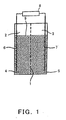
- FIG 1 shows an example of a battery having a cathode active material in the form of particles and an anode active material in the form of particles.
- an anode vessel 2 and a cathode vessel 3 are so defined as to face each other across an ion permeable fitter (separator) 1.
- An anode active material 4 in particle form is filled into the anode vessel 2, together with an electrolyte solution.
- a cathode active material 5 in particle form is filled into the cathode vessel 3, together with an electrolyte solution
- each active material particle is shown such that it has the same size as the other. In fact, these active material particles naturally differ in size from one another.
- the separator 1 is a fitter which has electrical insulation properties and which permits passage of ions therethrough, and is a membrane which does not permit passage of powdered and particulate material.
- As the material of the separator 1. for example, unglazed pottery, ion exchange resin membrane or high polymer fabric may be used.
- an anode current collector 6 which is an electrical conductor is disposed in the inside of the anode vessel 2
- a cathode current collector 7 which is an electrical conductor is disposed in the inside of the cathode vessel 3.
- the current collectors 6 and 7 are connected to a load means 8 (in the case of discharging) or to a power generating means 8 (in the case of charging).
- Reference numeral 9 denotes an electrolyte solution interface.
- Electrons are supplied from the anode current collector 6 by application of voltage to the battery.
- An electron released from the anode current collector 6 moves directly or through a powdered and particulate active material to the powdered and particulate active material of the anode and reacts.
- An ion generated by the reaction passes through the separator 1 and moves into the cathode vessel 3.
- the cathode vessel 3 the ion reacts with the powdered and particulate active material of the cathode and discharges an electron.
- the electron moves directly or through the powdered and particulate material to the cathode current collector 7, and is delivered to the power generating means 8.
- Electrons are supplied from the anode current collector 6 by application of load to the battery.
- An active material positive-ionized in the inside of the anode vessel 2 discharges electrons.
- An electron moves directly or through a powdered and particulate material to the anode current collector 6.
- An ion generated by the reaction passes through the separator 1 and moves into the cathode vessel 3.
- the cathoe vessel 3 the ion reacts with the powdered and particulate active material of the cathode and with an electron.
- An electron moves directly or through the powdered and particulate material to the cathode current collector 7, and is supplied to the load means 8.
- FIG. 2 is shown diagrammatically an example of a vessel structure of a three-dimensional battery of the layered type.
- Figure 2 shows a three-layered type three-dimensional battery.
- Cathode and anode vessels are formed through a separator 10 which undergoes no degeneration such as corrosion in an alkali electrolyte solution and which is capable of providing electrical insulation and of permitting passage of ions therethrough.
- a cathode active material 12 is loaded into the cathode vessel cell, together with an electrolyte (KOH, NaOH, LiOH and the like) solution, white an anode active material 14 is loaded into the anode vessel, together with an electrolyte (KOH, NaOH, LiOH and the like) solution.
- Each unit battery consisting of a cathode vessel and an anode vessel, is layered one upon the other in series through a respective dividing wall 16 made of a material which undergoes no degeneration such as corrosion in an alkali electrolyte solution, which does not permit passage of ions, and which has electrical conductive properties, and a cathode current collector 18 in contact with the cathode active material 12 is disposed in a vessel at one end while an anode current collector 20 in contact with the anode active material 14 is disposed in a vessel at the other end.
- the cathode current collector 18 and the anode current collector 20 are each made of a material which undergoes no degeneration such as corrosion in an alkali electrolyte solution, which does not permit passage of ions, and which has electrical conductive properties, and electricity is taken outside through these current collectors.
- a textile or nonwoven cloth made of any one of polytetrafluoroethylene, polyethylene, polypropylene, nylon and the like or membrane filter may be used.
- a nickel metal plate, a nickel metal foil, carbon, nickel-plated iron, nicket-plated stainless steel, nickel-plated carbon and the like may be used.
- the dividing wall 16, the cathode current collector 18, and the anode current collector 20 may be shaped like a flat plate. More preferably, these components are provided with projected portions in needle, plate, wave, particle, or the like form for the purpose of providing an increased current collecting area.
- Figure 5 shows an example cooling structure in which a bellows-shaped heat transfer tube 30, through which refrigerant flows, is disposed in the inside of a plate-like current collector (or a dividing wall) 28.
- Reference numeral 32 indicates a refrigerant inlet port.
- Reference numeral 34 indicates a refrigerant outlet port.
- an ion permeable current collector which has voids therein, which permits passage of ions therethrough, and which is electrically conductive, is added as a current collector for bypass, for providing an increased current collecting area by increasing the area of contact with the active material.
- a nickel metal mesh, a mesh-like body made of nickel-plated iron or nickel-plated stainless steel (for example, punching metal, expanded metal and the like), foamed nickel metal, niekel-plated foamed resin, nickel-plated carbon fibers, nickel-plated organic fibers, nickel-plated felt, nickel-plated inorganic fibers made of silica, alumina and the like, or nickel-plated foil made of inorganic substance such as mica may be used.
- an ion permeable current collector 22 is interposed between the separator 10 and the cathode active material 12 and the ion permeable current collector 22 is connected to the cathode current collector 18 to form a single current collector.
- Such an ion permeable current collector may be disposed on the separator side so that larger areas are brought into contact with the active material thereby increasing the current collecting area.
- active material substances of all kinds may be used as an active material which causes a cell reaction, regardless of the type of battery and regardless of cathode or anode.
- the cathode active material 12 comprises nickel hydroxide and the anode active material 14 comprises a hydrogen-occtuding alloy.
- the cathode active material 12 comprises nickel hydroxide and the anode active material 14 comprises cadmium.
- the active material may be in the form of powders.
- the active material may made of a particulate or plate-shaped material with an electrically conductive filler and a resin.
- the active material is combined with at least two of a separator, a dividing wall, and a current collector (including ion permeable current collector). And such a mixture is subjected to being formed integrally with one another in one piece, and the resultant formation is used as an electrode material. The way of producing such an electrode material will be described later.
- the electrically conductive filler comprises carbon fibers, nickel-plated carbon fibers, carbon particles, nickel-plated carbon particles, nickel-plated organic fibers, nickel-plated inorganic fibers made of silica, alumina and the like, nickel-plated foil made of inorganic substance such as mica, nickel in fiber form, nickel particles, nickel foil and the like.
- thermoplastic resins such as polyethylene, polypropylene, ethylene-vinyl acetate copolymer and the like may be used.
- a thermoplastic resin is melted by application of heat and is mixed with an active material to uniformly disperse the active material.
- a resin dissolved by a solvent is added.
- polyethylene, polypropylene, and ethylene-vinyl acetate copolymer are all soluble in solvents such as heated benzene, heated toluene, heated xylene and the like.
- a resin dissolved in such a solvent is mixed with an active material, and with an electrically conductive filler if necessary. Thereafter, the solvent is removed by evaporation, thereby making it possible to produce an active material forming product cured by the resin.
- reaction-curing resin epoxy resin, urethane resin, unsaturated polyester resin or the like may be used, and a thermosetting resin, e.g., phenol resin, may be used as a binder.
- a thermosetting resin e.g., phenol resin
- an active material forming product cured by the resin is prepared by extraction and removal of the solvent by the use of water.
- PES polyether sulfone
- DMSO dimethyl sulfoxide
- polystyrene is soluble in acetone.
- Polysulfone is soluble in dimethylformamide (DMF) and DMSO.
- Polyacrylonitrile is soluble in DMF, DMSO, and ethylene carbonate.
- Polyvinylidene fluoride is soluble in DMF, DMSO, and N-methyl-2-pyrrolidone (NMP).
- Polyamide is soluble in DMF and NMP.
- Polyimide is soluble in DMF and NMP.
- an active material forming product cured by the resin is prepared by extraction and removal of the solvent by the use of alcohol.
- acetyl cellulose is soluble in methylene chloride.
- Oxide phenylene ether (PPO) is soluble in methylene chloride.
- an active material shaped into particle, plate, or the like form may be coated with electrical conductive materials such as carbon fibers, nickel-plated carbon fibers, nickel-plated organic fibers, nickel-plated inorganic fibers made of silica, alumina and the like, nickel-plated foil made of inorganic substance such as mica, carbon powder, nickel-plated carbon powder, nickel in fiber form, nickel powders, nickel foil and the like.
- electrical conductive materials such as carbon fibers, nickel-plated carbon fibers, nickel-plated organic fibers, nickel-plated inorganic fibers made of silica, alumina and the like, nickel-plated foil made of inorganic substance such as mica, carbon powder, nickel-plated carbon powder, nickel in fiber form, nickel powders, nickel foil and the like.
- Such coating is carried out as follows. Before the active material formed substance is cured, a coating material such as any one of the above-described metal powders, metal fibers, metal-plated fibers and the like is added. By rolling, stirring or the like, the coating material is adhered to
- each of the forming products is placed in the uncured state by increasing the temperature of the forming product for softening by application of heat or by swelling and softening by addition of a solvent, and an impregnated metal is added to the forming product for impregnation.
- a surface of the active material in particle, plate, or the like form may be plated with nickel.
- a method of producing an electrode material of the three-dimensional battery in accordance with the present invention will be described.
- an active material of the above-described composition is combined with any one or at least two of a separator, a dividing wall, and a current collector (including an ion permeable current collector) so that they are formed integrally with one another in one piece.
- Such formation is carried out as follows. A mixture of a powdered active material with an electrically conducive filler and a resin is stirred. The mixture is integrally combined with a separator, a dividing wall and/or a current collector. Then, pressurized forming is tamed out while applying heat. In this case, the formation can be achieved by the use of a resin mixed with an electrically conductive filler without application of pressure.
- a resin thermoplastic resins such as polyethylene, polypropylene, ethylene-vinyl acetate copolymer and the like may be used.
- thermoplastic resin dissolved in a solvent such as heated toluene, heated xylene and the like is mixed with a powdered active material and an electrically conductive filler to uniformly disperse the active material and the filler. Then, the mixture is stirred and granulated to form granulated particles. These granulated particles are integrally combined with a separator, a dividing wall and/or a current collector. Then, pressurizede forming is carried out while applying heat. At this time, it is possible to cure the resin by evaporating the solvent contained in the forming product. Also in this case, the formation can be achieved by the use of a resin mixed with an electrically conductive filler without application of pressure.
- a solvent such as heated toluene, heated xylene and the like
- an active material shaped into particle, plate, or the like form is integrally formed in one piece with a separator, a dividing wall and/or a current collector, such formation can be carried out by re-dissolving the resin contained in the forming product without addition of a new resin.
- reaction-curing resin such as epoxy resin, urethane resin, unsaturated polyester resin and the like
- thermosetting resin such as phenol resin
- the aforesaid integral formation in one piece may be achieved by using, as a resin dissolved in a water-soluble solvent, a PES resin dissolved in DMSO, polystyrene dissolved in acetone, polysulfone dissolved in DMF or DMSO, polyacrylonitrile dissolved in DMF, DMSO, or ethylene carbonate, polyvinylidene fluoride dissolved in DMF, DMSO, or NMP, polyamide dissolved in DMF or NMP, or polyimide dissolved in DMF or NMP, in this case the solvent is extracted and removed from the forming product by the use of water.
- a resin dissolved in a water-soluble solvent a PES resin dissolved in DMSO, polystyrene dissolved in acetone, polysulfone dissolved in DMF or DMSO, polyacrylonitrile dissolved in DMF, DMSO, or ethylene carbonate, polyvinylidene fluoride dissolved in DMF, DMSO,
- the integral formation in one piece may be achieved by using, as a resin dissolved in an alcohol-soluble solvent, acetyl cellulose dissolved in methylene chloride, oxide phenylene ether (PPO) dissolved in methylene chloride or the like, in this case the solvent is extracted and removed from the forming product by the use of alcohol.
- a resin dissolved in an alcohol-soluble solvent acetyl cellulose dissolved in methylene chloride, oxide phenylene ether (PPO) dissolved in methylene chloride or the like, in this case the solvent is extracted and removed from the forming product by the use of alcohol.
- PPO oxide phenylene ether
- an active material is combined with at least two of a separator, a dividing wall, and a current collector, thereby reducing the number of component parts required at the time of three-dimensional battery assembly, the time required for assembly, and the costs of assembly.
- particulate graphite acetylene black
- the graphite particles were stirred at 1000 rpm for about three minutes to obtain thorough dispersion thereof.
- 1000 g of nickel hydroxide powders and 100 g of carbon fibers (trade name: DONA CARBO S-247) were added into the content of the mixer.
- the mixer was operated for performing mixing operation at 1000 rpm for about three minutes. This was followed by addition of 150 g of ethylene-vinyl acetate copolymer into the mixer. Then, mixing and stirring was carried out at a temperature of not less than the softening temperature nor more than 130 °C for ten minutes.
- the resultant substance i.e., a nickel hydroxide mixture
- a separator a nylon nonwoven cloth
- a pressure of 0.1 MPa was applied for achieving pressurized forming, and in such a state the temperature was reduced to cause the resin to cure.
- a forming product thus formed was removed from the mold frame. In this way, an electrode material comprising an integral formation in one piece of the active material with the separator was obtained.
- Nickel hydroxide powders, an electrically conductive filler, and a resin were mixed together with stirring in the same way as the first embodiment, to prepare a nickel hydroxide mixture.
- a separator (a nylon nonwoven cloth) was previously spread over the bottom of a mold frame having a cross section of 100 mm x 100 mm. Then, the nickel hydroxide mixture was poured, from above, onto the separator. The mixture was cooled as it was in the molding frame without application of pressure, thereby causing the resin to cure. A forming product thus formed was removed from the mold frame, in this way, an electrode material comprising an integral formation in one piece of the active material with the separator was obtained.
- Nickel hydroxide powders, an electrically conductive filler, and a resin were mixed together with stirring in the same way as the first embodiment, to prepare a nickel hydroxide mixture.
- a current collector (a nickel plate) was previously spread over the bottom of a mold frame having a cross section of 100 mm x 100 mm. Then, the nickel hydroxide mixture was poured, from above, onto the current collector. While applying heat from above, a pressure of 0.1 MPa was applied for achieving pressurized forming, and in such a state the temperature was reduced to cause the resin to cure. A forming product thus formed was removed from the mold frame. In this way, an electrode material comprising an integral formation in one piece of the active material with the current collector was obtained.
- Nickel hydroxide powders, an electrically conductive filler, and a resin were mixed together with stirring in the same way as the first embodiment, to prepare a nickel hydroxide mixture.
- a current collector (a nickel plate) was previously spread over the bottom of a mold frame having a cross section of 100 mm x 100 nm.
- the nickel hydroxide mixture was poured, from above, onto the current collector.
- the mixture was cooled as it was in the molding frame without application of pressure, thereby causing the resin to cure.
- a forming product thus formed was removed from the mold frame. In this way, an electrode material comprising an integral formation in one piece of the active material with the current collector was obtained.
- Nickel hydroxide powders, an electrically conductive filler, and a resin were mixed together with stirring in the same way as the first embodiment, to prepare a nickel hydroxide mixture.
- a separator a nylon nonwoven cloth
- the nickel hydroxide mixture was poured, from above, onto the separator.
- a current collector (a nickel plate) was placed on the filled nickel hydroxide mixture. While applying heat from above, a pressure of 0.1 MPa was applied for achieving pressurized forming, and in such a state the temperature was reduced to cause the resin to cure.
- a forming product thus formed was removed from the mold frame. In this way, an electrode material comprising an integral formation in one piece of the active material with the separator and the current collector was obtained.
- Nickel hydroxide powders, an electrically conductive filler, and a resin were mixed together with stirring in the same way as the first embodiment, to prepare a nickel hydroxide mixture.
- a separator a nylon nonwoven cloth
- the nickel hydroxide mixture was poured, from above, onto the separator.
- a current collector a nickel plate
- the mixture was cooled as it was in the molding frame without application of pressure, thereby causing the resin to cure.
- a forming product thus formed was removed from the mold frame. In this way, an electrode material comprising an integral formation in one piece of the active material with the separator and current collector was obtained.
- Nickel hydroxide powders, an electrically conductive filler, and a resin were mixed together with stirring in the same way as the first embodiment, to prepare a nickel hydroxide mixture.
- a separator (a nylon nonwoven cloth) was previously spread over the bottom of a mold frame having a cross section of 100 mm x 100 mm.
- an ion permeable current collector (a foamed nickel sheet) was placed on the separator.
- the nickel hydroxide mixture was poured from above. This was followed by placement of a current collector (a nickel plate) on the filled nickel hydroxide mixture. At this time, it was arranged such that the ion permeable current collector came into contact with the current collector.
- Nickel hydroxide powders, an electrically conductive fitter, and a resin were mixed together with stirring in the same way as the first embodiment, to prepare a nickel hydroxide mixture.
- a separator (a nylon nonwoven cloth) was previously spread over the bottom of a mold frame having a cross section of 100 mm x 100 mm.
- an ion permeable current collector (a foamed nickel sheet) was placed on the separator.
- the nickel hydroxide mixture was poured from above. This was followed by placement of a current collector (a nickel plate) on the filled nickel hydroxide mixture. At this time, it was arranged such that the ion permeable current collector came into contact with the current collector.
- particulate graphite acetylene black
- acetylene black particulate graphite
- the graphite particles were stirred at 1000 rpm for about three minutes to obtain thorough dispersion thereof.
- 1000 g of nickel hydroxide powders and 100 g of carbon fibers (trade name: DONACARBO S-247) were added to the content of the mixer.
- the mixer was operated for performing mixing operation at 1000 rpm for about three minutes.
- 150 g of ethylene-vinyl acetate copolymer was added to 1000 g of xylene heated to a temperature of 60 °C for dissolution therein.
- the resin dissolved in the heated xylene was added to a mixture of the nickel hydroxide powders and electrically conductive filler, heated to a temperature of 60 °C. While maintaining temperature at 60 °C by application of heat, the content of the Henschel mixer was stirred. Then, the Henschel mixer was cooled while still continuing stirring, and the mixed and kneaded substance was cooled and ground into powders. The powders were put into a high speed mixer and were entirely stirred by an agitator white at the same time controlling the size of granulated particles by means of a chopper. The internal volume of the high speed mixer used was 2 litters. The speed of rotation of the agitator used was 600 rpm.
- the speed of rotation of the chopper used was 1500 rpm. Under these conditions, the temperature of the powders was increased from room temperature up to 50°C with stirring. After generation of granulated particles, stirring was stopped while still continuing cooling. The particles contained therein xylene. Accordingly, the particles were placed in a reduced pressure dryer and heated to 50 °C for removal of the xylene therefrom. After being cooled, the particles were sieved with a sieve having a mesh size of 2.88 mm and with a sieve having a mesh size of 1 mm. As a result, granulated particles ranging in size between 1 mm and 2.88 mm were obtained.
- a current collector (a nickel plate) was previously spread over the bottom of a mold frame having a cross section of 100 mm x 100 mm. Then, the granulated particles were poured, from above, onto the current collector. While applying heat from above, a pressure of 0.1 MPa was applied for achieving pressurized forming, and in such a state the temperature was reduced to cause the resin to cure. A froming product thus formed was removed from the mold frame. In this way, an electrode material comprising an integral formation in one piece of the active material with the current collector was obtained.
- Nickel hydroxide powders, an electrically conductive filler, and a resin were mixed together with stirring for granulation in the same way as the ninth embodiment.
- a current collector (a nickel plate) was previously spread over the bottom of a mold frame having a cross section of 100 mm x 100 mm. Then, the granulated particles was poured, from above, onto the current collector. The granulated particles were cooled in the molding frame without application of pressure, thereby causing the resin to harden. A forming product thus formed was removed from the mold frame. In this way, an electrode material comprising an integral formation in one piece of the active material with the current collector was obtained.
- particulate graphite acetylene black
- acetylene black particulate graphite
- the graphite particles were stirred at 1000 rpm for about three minutes to obtain thorough dispersion thereof.
- 2500 g of hydrogeh-occluding alloy powders and 100 g of carbon fibers (trade name: DONACARBO S-247) were added to the content of the mixer.
- the mixer was operated for performing mixing operation at 1000 rpm for about three minutes.
- 150 g of ethylene-vinyl acetate copolymer was added to 1000 g of xylene heated to a temperature of 60 °C for dissolution therein.
- the resin dissolved in the heated xylene was added to a mixture of the hydrogen-occluding alloy powders and electrically conductive filler, heated to a temperature of 60 °C. While maintaining temperature at 60 °C by application of heat, the content of the Henschel mixer was stirred. Then, the Henschel mixer was cooled while still continuing stirring, and the mixed and kneaded substance was cooled and ground into powders. The powders were put if a high speed mixer and were entirely stirred by an agitator white, at the same time controlling the size of granulated particles by means of a chopper. The internal volume of the high speed mixer used was 2 litters. The speed of rotation of the agitator used was 600 rpm.
- the speed of rotation of the chopper used was 1500 rpm. Under these conditions, the temperature of the powders was increased from room temperature to 50 °C with stirring. After generation of granulated particles, stirring was stopped while still continuing cooling. The particles contained therein xylene. Accordingly, the particles were placed in a reduced pressure dryer and heated to 50 °C for removal of the xylene therefrom. After being cooled, the particles were sieved with a sieve having a mesh size of 2.88 mm and with a sieve having a mesh size of 1 mm. As a result, granulated particles ranging in size between 1 mm and 2.88 mm were obtained.
- a current collector (a nickel plate) was previously spread over the bottom of a mold frame having a cross section of 100 mm x 100 mm. Then, the granulated particles were poured, from above, onto the current collector. While applying heat from above, a pressure of 0.1 MPa was applied for achieving pressurized forming, and in such a state the temperature was reduced to cause the resin to cure. A forming product thus formed was removed from the mold frame. In this way, an electrode material comprising an integral formation in one piece of the active material with the current collector was obtained.
- particulate graphite acetylene black
- sand Toyoura standard sand
- carbon fibers trade name: DONACARBO S-247
- the resin dissolved in the heated xylene was added to a mixture of the sand and electrically conductive filler, heated to a temperature of 60 °C. While maintaining temperature at 60 degrees Centigrade by application of heat, the content of the Henschel mixer was stirred. Then, the Henschel mixer was cooled while still continuing stirring, and the mixed/kneaded substance was cooled and ground to powders. The powders were put into a high speed mixer and were entirely stirred by an agitator while at the same time controlling the size of granulated particles by means of a chopper. The internal volume of the high speed mixer used was 2 litters. The speed of rotation of the agitator used was 600 rpm.
- the speed of rotation of the chopper used was 1500 rpm. Under these conditions, the temperature of the powders was increased from room temperature to 50 °C with stirring. After generation of granulated particles, stirring was stopped while still continuing cooling. The particles contained therein xylene. Accordingly, the particles were placed in a reduced pressure dryer and heated to 50 °C for removal of the xylene therefrom. After being cooled, the particles were sieved with a sieve having a mesh size of 2.88 mm and with a sieve having a mesh size of 1 mm. As a result, granulated particles ranging in size between 1 mm and 2.88 mm were obtained.
- a current collector (a nickel plate) was previously spread over the bottom of a mold frame having a cross section of 100 mm x 100 mm. Then, the granulated particles were poured, from above, onto the current collector. While applying heat from above, a pressure of 0.1 MPa was applied for achieving pressurized forming, and in such a state the temperature was reduced to cause the resin to cure. A forming product thus formed was removed from the mold frame. In this way, an electrode material comprising an integral formation in one piece of the active material with the current collector was obtained.
- particulate graphite acetylene black
- acetylene black particulate graphite
- the graphite particles were stirred at 1000 rpm for about three minutes to obtain thorough dispersion thereof.
- 1000 g of particulate coal prowdered coal of Daido coal
- 100 g of carbon fibers trade name: DONACARBO S-247
- the mixer was operated for performing mixing operation at 1000 rpm for about three minutes.
- 150 g of ethylene-vinyl acetate copolymer was added to 1000 g of xylene heated to a temperature of 60 °C for dissolution therein.
- the resin dissolved in the heated xylene was added to a mixture of the coal and electrically conductive filler, heated to a temperature of 60 °C. While maintaining temperature at 60 degrees Centigrade by application of heat, the content of the Henschel mixer was stirred. Then, the Henschel mixer was cooled while still continuing stirring, and the mixed and kneaded substance was cooled and ground to powders.
- the powders were put in a high speed mixer and were entirety stirred by an agitator while at the same time controlling the size of granulated particles by means of a chopper.
- the internal volume of the high speed mixer used was 2 litters.
- the speed of rotation of the agitator used was 600 rpm.
- the speed of rotation of the chopper used was 1500 rpm.
- the temperature of the powders was increased from room temperature to 50 °C with stirring. After generation of granulated particles, stirring was stopped while still continuing cooling.
- a current collector (a nickel plate) was previously spread over the bottom of a mold frame having a cross section of 100 mm x 100 mm. Then, the granulated particles were poured, from above, onto the current collector. While applying heat from above, a pressure of 0.1 MPa was applied for achieving pressurized forming, and in such a state the temperature was reduced to cause the resin to cure. A forming product thus formed was removed from the mold frame. In this way, an electrode material comprising an integral formation in one piece of the active material with the current collector was obtained.
- particulate graphite acetylene black
- acetylene black particulate graphite
- the graphite particles were stirred at 1000 rpm for about three minutes to obtain thorough dispersion thereof.
- 500 g of charcoal prepared by calcining wood at 600 °C for two hours
- 100 g of carbon fibers (trade name: DONACARBO S-247) were added to the content of the mixer.
- the mixer was operated for performing mixing operation at 1000 rpm for about three minutes.
- 150 g of ethylene-vinyl acetate copolymer was added to 1000 g of xylene heated to a temperature of 60 °C for dissolution therein.
- the resin dissolved in the heated xylene was added to a mixture of the charcoal and electrically conductive filler, heated to a temperature of 60 °C. While maintaining temperature at 60 °C by application of heat, the content of the Henschel mixer was stirred. Then, the Henschel mixer was cooled while still continuing stirring, and the mixed and kneaded substance was cooled and ground to powders. The powders were put in a high speed mixer and were entirely stirred by an agitator while at the same time controlling the size of granulated particles by means of a chopper.
- the internal volume of the high speed mixer used was 2 litters.
- the speed of rotation of the agitator used was 600 rpm.
- the speed of rotation of the chopper used was 1500 rpm.
- the temperature of the powders was increased from room temperature to 50 °C with stirring. After generation of granulated particles, stirring was stopped while still continuing cooling.
- a current collector (a nickel plate) was previously spread over the bottom of a mold frame having a cross section of 100 mm x 100 mm. Then, the granulated particles were poured, from above, onto the current collector. While applying heat from above, a pressure of 0.1 MPa was applied for achieving pressurized forming, and in such a state the temperature was reduced to cause the resin to cure. A forming product thus formed was removed from the mold frame. In this way, an electrode material comprising an integral formation in one piece of the active material with the current collector was obtained.
- particulate graphite acetylene black
- Henschel mixer having an internal volume of 10 litters.
- the graphite particles were stirred at 1000 rpm for about three minutes to obtain thorough dispersion thereof.
- 500 g of silica obtained by calcining chaff at 600 °C for two hours
- 100 g of carbon fibers (trade name: DONACARBO S-247) were added to the content of the mixer.
- the mixer was operated for performing mixing operation at 1000 rpm for about three minutes.
- 150 g of ethytene-vinyl acetate copolymer was added to 1000 g of xylene heated to a temperature of 60 °C for dissolution therein.
- the resin dissolved in the heated xylene was added to a mixture of the silica and electrically conductive filler, heated to a temperature of 60 °C. While maintaining temperature at 60 °C by application of heat, the content of the Henschel mixer was stirred. Then, the Henschel mixer was cooled while still continuing stirring, and the mixed and kneaded substance was cooled and ground to powders.
- the powders were put in a high speed mixer and were entirety stirred by an agitator while at the same time controlling the size of granulated particles by means of a chopper.
- the internal volume of the high speed mixer used was 2 litters.
- the speed of rotation of the agitator used was 600 rpm.
- the speed of rotation of the chopper used was 1500 rpm.
- the temperature of the powders was increased from room temperature up to 50 °C with stirring. After generation of granulated particles, stirring was stopped white still continuing cooling.
- the particles were sieved with a sieve having a mesh size of 2.88 mm and with a sieve having a mesh size of 1 mm. As a result, granulated particles ranging in size between 1 mm and 2.88 mm were obtained.
- a current collector (a nickel plate) was previously spread over the bottom of a mold frame having a cross section of 100 mm x 100 mm. Then, the granulated particles were poured, from above, onto the current collector. While applying heat from above, a pressure of 0.1 MPa was applied for achieving pressurized forming, and in such a state the temperature was reduced to cause the resin to cure. A forming product thus formed was removed from the mold frame. In this way, an electrode material comprising an integral formation in one piece of the active material with the current collector was obtained.
- particulate graphite acetylene black
- slag prepared by melting refuse incineration ash at 1500 °C and then by cooling it
- carbon fibers trade name: DONACARBO S-247
- the resin dissolved in the heated xylene was added to a mixture of the slag and electrically conductive filler, heated to a temperature of 60 °C. While maintaining temperature at 60 °C by application of heat, the content of the Henschel mixer was stirred. Then, the Henschel mixer was cooled while still continuing stirring, and the mixed and kneaded substance was cooled and ground to powders.
- the powders were put in a high speed mixer and were entirety stirred by ah agitator while at the same time controlling the size of granulated particles by means of a chopper.
- the internal volume of the high speed mixer used was 2 lifters.
- the speed of rotation of the agitator used was 600 rpm.
- the speed of rotation of the chopper used was 1500 rpm. Under these conditions, the temperature of the powders was increased from room temperature to 50 °C with stirring. After generation of granulated particles, stirring was stopped while still continuing cooling. The particles contained therein xylene. Accordingly, the particles were placed in a reduced pressure dryer and were heated to 50 °C for removal of the xylene therefrom After being cooled, the particles were sieved with a sieve having a mesh size of 2.88 mm and with a sieve having a mesh size of 1 mm. As a result, granulated particles ranging in size between 1 mm and 2.88 mm were obtained.
- a current collector (a nickel plate) was previously spread over the bottom of a mold frame having a cross section of 100 mm x 100 mm. Then, the granulated particles were poured, from above, onto the current collector. While applying heat from above, a pressure of 0.1 MPa was applied for achieving pressurized forming, and in such a state the temperature was reduced to cause the resin to cure. A forming product thus formed was removed from the mold frame. In this way, an electrode material comprising an integral formation in one piece of the active material with the current collector was obtained.
- particulate graphite acetylene black
- Henschel mixer having an internal volume of 10 litters.
- the graphite particles were stirred at 1000 rpm for about three minutes to obtain thorough dispersion thereof.
- 500 g of carbon prepared by calcining carbon fibers at 1100 °C was added to the content of the mixer.
- the mixer was operated for performing mixing operation at 1000 rpm for about three minutes.
- 150 g of ethylene-vinyl acetate copolymer was added to 1000 g of xylene heated to a temperature of 60 °C for dissolution therein.
- the resin dissolved in the heated xylene was added to a mixture of the carbon and electrically conductive filler, heated to a temperature of 60 °C. While maintaining temperature at 60 °C by application of heat, the content of the Henschel mixer was stirred. Then, the Henschel mixer was cooled while still continuing stirring, and the mixed and kneaded substance was cooled and ground to powders. The powders were put in a high speed mixer and were entirely stirred by an agitator while at the same time controlling the size of granulated particles by means of a chopper.
- the internal volume of the high speed mixer used was 2 litters.
- the speed of rotation of the agitator used was 600 rpm.
- the speed of rotation of the chopper used was 1500 rpm.
- the temperature of the powders was increased from room temperature up to 50°C with stirring. After generation of granulated particles, stirring was stopped while still continuing cooling.
- a current collector (a nickel plate) was previously spread over the bottom of a mold frame having a cross section of 100 mm x 100 mm. Then, the granulated particles were poured, from above, onto the current collector. While applying heat from above, a pressure of 0.1 MRa was applied for achieving pressurized forming, and in such a state the temperature was reduced to cause the resin to cure. A forming product thus formed was removed from the mold frame. In this way, an electrode material comprising an integral formation in one piece of the active material with the current collector was obtained.
- Nickel hydroxide powders, an electrically conductive filler, and a resin were mixed together with stirring in the same way as the first embodiment, to prepare a nickel hydroxide mixture.
- a current collector provided with projected portions as shown in Figures 3 and 4 (a nickel current collector designed for a battery cell internal size of 100 mm x 100 mm x 10 mm: a current collector provided with 8 mm-long projected portions at pitches of 10 mm) was prepared. The current collector provided with such projected portions was previously spread over the bottom of a mold frame having a cross section of 100 mm by 100 mm. Then, the nickel hydroxide mixture was poured, from above, onto the current collector.
- Nickel hydroxide powders, an electrically conductive filler, and a resin were mixed together with stirring in the same way as the first embodiment, to prepare a nickel hydroxide mixture.
- a current collector having a cooling structure as shown in Figure 5 (a nickel current collector designed for a battery cell internal size of 100 mm x 100 mm x 10 mm: a current collector in which is disposed a heat transfer pipe through which a refrigerant such as water flows) was prepared.
- the current collector provided with such a cooling structure was previously spread over the bottom of a mold frame having a cross section of 100 mm x 100 mm. Then, the nickel hydroxide mixture was poured, from above, onto the current collector.
- the present embodiment is a battery that is constructed of a single basic unit alone.
- a resin and an electrically conductive filler are added to an active material substance which causes a cell reaction, and the mixture is formed and cured to prepare an active material forming product in particle, plate, block, rod, or the like form.
- an active material substance in the form of powders may be used as it is.
- a secondarily formed active material in the form of particles may be used.
- a powdered or particulate active material like paste by the use of PVA or the like may be used.
- Active material substances of all kinds may be used to form an active material capable of causing a cell reaction, regardless of the type of battery and regardless of cathode or anode.
- nickel-hydrogen secondary batteries for example, 2000 g of nickel hydroxide powders, 200 g of EVA resin, and 300 g of electrically conductive filler (carbon black and carbon fibers) are mixed together and, thereafter, the mixture is subjected to pressurized forming by application of a pressure of 0.1 MPa to form a plate-like cathode active material 40 (100 mm x 30 mm x 3 mm (thickness)).
- nickel-hydrogen secondary batteries for example, 6000 g of hydrogen-occluding alloy powders, 200 g of EVA resin, and 300 g of electrically conductive filler (carbon black and carbon fibers) are mixed together and, thereafter, the mixture is subjected to pressurized forming by application of a pressure of 0.1 MPa to form a plate-like anode active material 42 (100 mm x 30 mm x 2 mm (thickness)).
- the cathode and anode active materials 40, 42 are each coated with an ion permeable current collector 44.
- an ion permeable current collector 44 For example, for the ease of each plate-like active material, any surface(s) (from one to six surfaces) thereof may be coated with the ion permeable current collector 44.
- the active material may be coated with an ion permeable current collector for integral formation.
- the active material is filled in an ion permeable current collector in the form of a sack.
- the ion permeable current collector 44 (a foamed nickel sheet).
- the material of the ion permeable current collector that has voids therein, permits passage of ions and is electrically conductive a nickel metal mesh, a nickel-plated punching metal, a metal such as expanded metal, a nickel-plated foamed resin such as urethane, nickel-plated porous material such as polyethylene, polypropylene, nylon, cotton, carbon fibers and the like, nickel-plated inorganic fibers made of silica, alumina and the like, nickel-plated organic fibers, nickel-plated felt, or nickel-plated foil made of inorganic substance such as mica, may be used in addition to the foamed nickel metal.
- a bellows-shaped separator 46 consisting of a material which undergoes no degeneration such as corrosion in an alkali electrolyte solution and which is capable of both providing electrical insulation and permitting passage of ions therethrough, is disposed.
- Cathode active materials 40 and anode active materials 42 when loaded in the battery cell, are placed alternately on the contact side with a cathode current collector 48 and on the contact side with ah anode current collector 50, respectively, facing each other across the separator 46.
- a basic unit thus prepared is loaded, together with an electrolyte (KOH, NaOH, LiOH and the like) solution, between the cathode current collector 48 and the anode current collector 50 in the battery cell to complete a battery.
- a textile or nonwoven cloth made of any one of polytetrafluoroethylene, Polyethylene, polypropylene, nylon and the like, or membrane filter may be used.
- a nickel metal plate, a nickel metal foil, carbon, nickel-plated iron, nickel-plated stainless steel, nickel-plated carbon and the like may be used.
- the structure of the bellows-shaped unit which is a basic unit, is not limited to the one made up of a pair of cathode active materials and a pair of anode active materials, as shown in Fig.6 .
- the bellows-like unit may be produced by adequately selecting a structure.
- the bellows-shaped unit may be formed using a minimum structure as shown in Figure 7 or a structure made up of any number of pairs of cathode and anode active materials.
- a voltage is applied to the battery for the supply of electrons from a power generating means (not shown) to the anode current collector 50.
- the electrons move from the anode current collector 50 to the anode active material 42 and react. Ions generated by the reaction pass through the separator 46, react with the cathode active material, 40, and discharge electrons. These electrons move to the cathode current collector 48, and are delivered to the power generating means.
- Electrons are supplied from a load to the cathode current collector 48.
- the electrons move from the cathode current collector 48 to the cathode active material 40 and react.
- Ions generated by the reaction pass through the separator 46, react with the anode active material 42, and discharge electrons. These electrons move to the anode current collector 50, and are delivered to the load.
- the distance between the cathode active material 40 and the anode active material 42 is short, and the distance for which electrons move becomes short, thereby achieving high output powers.
- the length for which ions diffuse becomes short, thereby achieving excellent diffusion of ions.
- the gas flows to its opposite electrode and is likely to be consumed easily, and sealing is established easily.
- the cathode active material 40 and the anode active material 44 both of which are covered with the ion permeable current collector 44 made of porous nickel, are used, this shortens the distance between the active material and the current collector, thereby making the moving distance of electrons shorter, and the current collecting area is increased. As a result, high performance batteries of small electrical resistance are obtained.
- the filling amount of the cathode and anode active materials 40, 42 per unit volume is small, thereby making a possible to hold a plenty of electrolytic solution within the cell. Accordingly, the dry out phenomenon, in which a solid-liquid reaction (a cell reaction) will no longer occur due to electrolytic solution depletion, is unlikely to occur.
- FIG. 8 is shown an example of a second embodiment of the high power type three-dimensional battery in accordance with the present invention.
- a plurality of basic units (for example, four basic units in Fig. 8 ) are incorporated in parallel to constitute a battery.
- a basic unit 52 a bellows-shaped basic unit as described in the first embodiment is produced.
- Four basic units 52 are loaded in parallel between the cathode current collector 48 and the anode current collector 50 for constitution of a battery.
- a third embodiment of the high power type three-dimensidnal battery in accordance with the present invention.
- a plurality of basic units for example, four basic units in Fig. 9
- a plurality of such layers are placed one upon the other to constitute a battery.
- the basic unit 52 a bellows-shaped basic unit as described in the first embodiment is produced.
- Four basic units 52 are loaded in parallel into a battery cell in the form of layers.
- Four such layers are placed one upon the other through respective dividing walls 54 to constitute a battery. If tells are placed in series one upon the other, this provides a high voltage battery.
- As the material of the dividing wall 54 a nickel metal plate, a nickel metal foil, carbon, nickel-plated iron, nickel-plated stainless steel, nickel-plated carbon, or the like may be used.
- the arrangement that a plurality of bellows-shaped basic units are loaded in a battery cell makes it possible to easily achieve an increase in battery size and, in addition, since there are no welds causing the electrical resistance to increase, this prevents the drop in performance due to the increase in size. Additionally, it becomes possible to reduce production cost and production time.
- a battery is constituted of a single basic unit and, in comparison with the first embodiment, the present embodiment employs a thicker active material in order to provide a battery with a great volume energy density.
- a thicker active material for example, for the case of nickel-hydrogen secondary batteries, 2000 g of nickel hydroxide powders, 200 g of EVA resin, and 300 g of electrically conductive filler (carbon black and carbon fibers) are mixed together.
- the mixture is subjected to pressurized forming by application of a pressure of 0.1 MPa to form a plate-like cathode active material 40 (100 mm ⁇ 30 mm x 12 mm (thickness)).
- a pressure of 0.1 MPa for example, 6000 g of hydrogen-occluding alloy powder, 200 g of EVA resin, and 300 g of electrically conductive filler (carbon black and carbon fibers) are mixed together.
- the mixture is subjected to pressurized forming by application of a pressure of 0.1 MPa to form a plate-like anode active material 42 (100 mm x 30 mm x 8 mm (thickness)).
- any aurface(s) for example, four surfaces
- the ion permeable current collector 44 after which bellows-shaped cathode active materials 40 and anode active materials 42 are incorporated so that they face each other across the separator 46.
- the basic unit thus prepared is loaded, together with an electrolytic solution, between the cathode current collector 48 and the anode current collector 50 in the battery cell for constitution of a battery.
- the thickness of active material is increased, this relatively reduces the ratio of the separator 46 and the ion permeable current collector 44. As a result, despite the drop in output power per volume it becomes possible to obtain a battery having a high volume energy density.
- the thickness of active Material is reduced because high power battery performance is required in the aforesaid embodiments, this relatively increases the ratio of the separator 46 and the ion permeable type current collector 44. As a result, despite the drop in volume energy density it becomes possible to obtain a high power battery.
- any changes to the battery specification can be made just by increasing or decreasing the thickness of active material and the like, and desired battery specifications are obtained easily.
- a bellows-shaped unit (a basic unit) of the present embodiment comprising cathode and anode active materials which are so incorporated as to face each other across a separator
- the number of cathode active materials is greater than the number of anode active materials by one, or vice versa, and either the cathode active materials or the anode active materials, whichever are greater in number, are disposed at each end of the basic unit.
- anode active materials 42 are disposed on both sides of a cathode active material 40, with a bellow-shaped separator 46 sandwiched between the cathode active material 40 and each anode active material 42.
- Other structures and operations are the same as the first embodiment.
- the bellows-shaped basic unit of the present embodiment may be produced by adequately selecting a structure ranging from a minimum structure shown in Figure 11 to a structure provided with any arbitrary number of basic units.
- FIG. 13 shows examples of a sixth embodiment of the high power type three-dimensional battery in accordance with the present invention.
- an ion permeable current collector is disposed at a certain position in cathode active material and anode active material.
- Figure 13 shows an example in which three surfaces of a plate-like anode active material 42 are covered with an ion permeable current collector 44, indicating that any surface(s) of the cathode active material 40 and anode active material 42 can be coated with the ion permeable current collector 44.
- Figures 14-17 each show an example in which an ion permeable current collector 44 is disposed on a surface of the anode active material 42 and inside thereof, indicating that that the ion permeable current collectors 44 can be disposed at any place(s) of the cathode active material 40 and anode active material 42. Even in the case where an ion permeable current collector is disposed inside the cathode and anode active materials, the distance between the active material and the current collector is reduced and the moving distance of electrons is reduced. The current collector area increases and a high performance battery having a small electric resistance is obtained.
- the present invention since it is constructed in the way as describe above, makes it possible to reduce the number of component parts required at the time of assembling a battery. Therefore, the present invention provides a three-dimensional battery and its electrode structure requiring less assembly time and less assembly cost. The present invention further provides a three-dimensional battery capable of being increased easily in size and of producing high output powers without-undergoing a drop in performance due to the incerase in size.
Applications Claiming Priority (3)
| Application Number | Priority Date | Filing Date | Title |
|---|---|---|---|
| JP2001284491 | 2001-09-19 | ||
| JP2001284489 | 2001-09-19 | ||
| EP02799469A EP1435673B1 (de) | 2001-09-19 | 2002-09-13 | Dreidimensionale zelle, ihre elektrodenstruktur und verfahren zur herstellung eines elektrodenmaterials einer dreidimensionalen zelle |
Related Parent Applications (2)
| Application Number | Title | Priority Date | Filing Date |
|---|---|---|---|
| EP02799469A Division EP1435673B1 (de) | 2001-09-19 | 2002-09-13 | Dreidimensionale zelle, ihre elektrodenstruktur und verfahren zur herstellung eines elektrodenmaterials einer dreidimensionalen zelle |
| EP02799469.8 Division | 2002-09-13 |
Publications (3)
| Publication Number | Publication Date |
|---|---|
| EP1947711A2 true EP1947711A2 (de) | 2008-07-23 |
| EP1947711A3 EP1947711A3 (de) | 2008-09-03 |
| EP1947711B1 EP1947711B1 (de) | 2012-07-11 |
Family
ID=26622471
Family Applications (2)
| Application Number | Title | Priority Date | Filing Date |
|---|---|---|---|
| EP08006222A Expired - Lifetime EP1947711B1 (de) | 2001-09-19 | 2002-09-13 | Dreidimensionale Batterie und ihre Elektrodenstruktur sowie Verfahren zur Herstellung von Elektrodenmaterial von dreidimensionalen Batterien |
| EP02799469A Expired - Lifetime EP1435673B1 (de) | 2001-09-19 | 2002-09-13 | Dreidimensionale zelle, ihre elektrodenstruktur und verfahren zur herstellung eines elektrodenmaterials einer dreidimensionalen zelle |
Family Applications After (1)
| Application Number | Title | Priority Date | Filing Date |
|---|---|---|---|
| EP02799469A Expired - Lifetime EP1435673B1 (de) | 2001-09-19 | 2002-09-13 | Dreidimensionale zelle, ihre elektrodenstruktur und verfahren zur herstellung eines elektrodenmaterials einer dreidimensionalen zelle |
Country Status (8)
| Country | Link |
|---|---|
| US (1) | US20040241540A1 (de) |
| EP (2) | EP1947711B1 (de) |
| JP (2) | JPWO2003028142A1 (de) |
| KR (2) | KR100620637B1 (de) |
| CN (2) | CN100486027C (de) |
| AT (1) | ATE518272T1 (de) |
| ES (1) | ES2390375T3 (de) |
| WO (1) | WO2003028142A1 (de) |
Cited By (1)
| Publication number | Priority date | Publication date | Assignee | Title |
|---|---|---|---|---|
| CN109095473A (zh) * | 2018-08-22 | 2018-12-28 | 吉林唯圣能源科技开发有限公司 | 二氧化硅的低成本制备方法及硅碳负极材料的低成本制备方法 |
Families Citing this family (73)
| Publication number | Priority date | Publication date | Assignee | Title |
|---|---|---|---|---|
| CN1327545C (zh) * | 2004-12-09 | 2007-07-18 | 英赛尔科技(深圳)有限公司 | 用于制造软包装锂电池或聚合物锂电池的隔膜粘接胶 |
| JP4581888B2 (ja) * | 2005-07-25 | 2010-11-17 | Tdk株式会社 | 電気化学素子用電極の製造方法および電気化学素子の製造方法 |
| US20110171518A1 (en) * | 2005-08-12 | 2011-07-14 | The Government Of The United States Of America, As Represented By The Secretary Of The Navy | Three dimensional Battery Architectures and Methods of Making Same |
| US8883354B2 (en) | 2006-02-15 | 2014-11-11 | Optodot Corporation | Separators for electrochemical cells |
| JP4634322B2 (ja) * | 2006-03-02 | 2011-02-16 | 住友電気工業株式会社 | 電池用電極 |
| US7667432B2 (en) * | 2006-04-27 | 2010-02-23 | Tesla Motors, Inc. | Method for interconnection of battery packs and battery assembly containing interconnected battery packs |
| FR2906083B1 (fr) * | 2006-09-15 | 2010-10-29 | Accumulateurs Fixes | Electrode plastifiee pour accumulateur alcalin. |
| US8999558B2 (en) * | 2007-01-12 | 2015-04-07 | Enovix Corporation | Three-dimensional batteries and methods of manufacturing the same |
| US8691450B1 (en) | 2007-01-12 | 2014-04-08 | Enovix Corporation | Three-dimensional batteries and methods of manufacturing the same |
| US9166230B1 (en) * | 2007-01-12 | 2015-10-20 | Enovix Corporation | Three-dimensional battery having current-reducing devices corresponding to electrodes |
| CN102244222A (zh) * | 2007-02-14 | 2011-11-16 | 川崎重工业株式会社 | 电池及其传热结构 |
| EP2849265B1 (de) * | 2008-02-22 | 2021-05-12 | Colorado State University Research Foundation | Lithium-Ionen-Batterie |
| RU2465157C2 (ru) | 2008-02-29 | 2012-10-27 | Кавасаки Дзукогио Кабусики Кайся | Система электроснабжения электрической железной дороги |
| US8475957B2 (en) | 2008-04-17 | 2013-07-02 | Enovix Corporation | Negative electrode structure for non-aqueous lithium secondary battery |
| JP2009284690A (ja) * | 2008-05-23 | 2009-12-03 | Kawasaki Heavy Ind Ltd | 電池駆動車両 |
| DE102008059949B4 (de) * | 2008-12-02 | 2013-11-07 | Daimler Ag | Batterie, Verfahren zur Herstellung einer Batterie und Verwendung der Batterie |
| US8691340B2 (en) | 2008-12-31 | 2014-04-08 | Apinee, Inc. | Preservation of wood, compositions and methods thereof |
| JP5393181B2 (ja) * | 2009-01-30 | 2014-01-22 | 川崎重工業株式会社 | 密閉式角形電池および密閉式角形電池の組立方法 |
| CN101531409B (zh) * | 2009-04-17 | 2011-02-09 | 清远市灵捷制造化工有限公司 | 一种用于废水微电解处理的微电极 |
| CN102460772A (zh) | 2009-05-26 | 2012-05-16 | 奥普图多特公司 | 利用直接涂覆在纳米孔隔板上的电极的电池 |
| US20110027648A1 (en) * | 2009-07-30 | 2011-02-03 | The Government of the States of America, as represented by the Secretary of the Navy | Three-dimensional microbattery with tricontinuous components |
| WO2011030697A1 (en) * | 2009-09-11 | 2011-03-17 | Semiconductor Energy Laboratory Co., Ltd. | Power storage device and method for manufacturing the same |
| KR200453689Y1 (ko) * | 2009-10-13 | 2011-05-23 | 비전엑스아시아 주식회사 | 차량용 바형 엘이디 조명장치 |
| WO2011098795A1 (en) * | 2010-02-09 | 2011-08-18 | Bae Systems Plc | Component including a rechargeable battery |
| EP2534716B1 (de) * | 2010-02-09 | 2017-08-02 | BAE Systems PLC | Komponente enthaltend eine wiederaufladbare batterie |
| CN102214822A (zh) * | 2010-04-09 | 2011-10-12 | 国立清华大学 | 负极电极复合材料其制法及使用其的电化学装置 |
| CN102237199A (zh) * | 2010-04-21 | 2011-11-09 | 财团法人金属工业研究发展中心 | 电储存装置、电储存装置的电极组及其制造方法 |
| JP5917027B2 (ja) | 2010-06-30 | 2016-05-11 | 株式会社半導体エネルギー研究所 | 電極用材料の作製方法 |
| WO2012011944A2 (en) | 2010-07-19 | 2012-01-26 | Optodot Corporation | Separators for electrochemical cells |
| CN103098263B (zh) * | 2010-09-09 | 2016-01-20 | 加州理工学院 | 电化学能量存储系统和方法 |
| US9843027B1 (en) | 2010-09-14 | 2017-12-12 | Enovix Corporation | Battery cell having package anode plate in contact with a plurality of dies |
| EP2535970A1 (de) * | 2011-06-14 | 2012-12-19 | BAE Systems Plc | Komponente mit wiederaufladbarer Batterie |
| US9865880B2 (en) * | 2011-06-14 | 2018-01-09 | Bae Systems Plc | Component including a rechargeable battery |
| US9878464B1 (en) | 2011-06-30 | 2018-01-30 | Apinee, Inc. | Preservation of cellulosic materials, compositions and methods thereof |
| US9379368B2 (en) | 2011-07-11 | 2016-06-28 | California Institute Of Technology | Electrochemical systems with electronically conductive layers |
| CN103650204B (zh) | 2011-07-11 | 2016-11-16 | 加州理工学院 | 用于电化学系统的新颖分隔物 |
| CN104115325B (zh) | 2012-01-24 | 2017-02-22 | 艾诺维克斯公司 | 用于能量存储装置的离子透过结构 |
| US8841030B2 (en) | 2012-01-24 | 2014-09-23 | Enovix Corporation | Microstructured electrode structures |
| CN104081571B (zh) * | 2012-01-30 | 2016-11-09 | 日本特殊陶业株式会社 | 燃料电池 |
| GB201203997D0 (en) * | 2012-03-07 | 2012-04-18 | Bae Systems Plc | Electrical energy storage structures |
| KR102480368B1 (ko) | 2012-08-16 | 2022-12-23 | 에노빅스 코오퍼레이션 | 3차원 배터리들을 위한 전극 구조들 |
| JP6058987B2 (ja) * | 2012-11-29 | 2017-01-11 | 京セラ株式会社 | 二次電池 |
| CN103972447B (zh) * | 2013-01-28 | 2017-02-08 | 海洋王照明科技股份有限公司 | 电化学电源隔膜及其制备方法、电化学电池或电容器 |
| KR102659783B1 (ko) | 2013-03-15 | 2024-04-22 | 에노빅스 코오퍼레이션 | 3차원 배터리들을 위한 분리기들 |
| KR102236436B1 (ko) | 2013-04-29 | 2021-04-06 | 옵토도트 코포레이션 | 증가된 열 전도율을 갖는 나노기공성 복합체 분리기들 |
| US9666907B2 (en) | 2013-09-03 | 2017-05-30 | Ut-Battelle, Llc | Thermal management for high-capacity large format Li-ion batteries |
| US20150171398A1 (en) | 2013-11-18 | 2015-06-18 | California Institute Of Technology | Electrochemical separators with inserted conductive layers |
| US10714724B2 (en) | 2013-11-18 | 2020-07-14 | California Institute Of Technology | Membranes for electrochemical cells |
| DE102013114121B4 (de) * | 2013-12-16 | 2017-08-17 | Eisenhuth Gmbh & Co. Kg | Verfahren zur Herstellung einer Bipolarplatte |
| DE102014202337A1 (de) | 2014-02-10 | 2015-08-13 | Robert Bosch Gmbh | Gehäuse mit verbesserter Wärmeleitung |
| JP6317222B2 (ja) * | 2014-09-22 | 2018-04-25 | 日本特殊陶業株式会社 | 固体酸化物形燃料電池スタック |
| US10381623B2 (en) | 2015-07-09 | 2019-08-13 | Optodot Corporation | Nanoporous separators for batteries and related manufacturing methods |
| TWI715576B (zh) | 2015-05-14 | 2021-01-11 | 美商易諾維公司 | 用於能量儲存裝置之縱向約束 |
| KR102568787B1 (ko) | 2015-09-21 | 2023-08-21 | 삼성전자주식회사 | 3차원 리튬 이차전지용 양극 및 그 제조방법 |
| KR102514595B1 (ko) | 2015-10-12 | 2023-03-27 | 삼성전자주식회사 | 3차원 구조의 전극 구조체 및 이를 갖는 전지 |
| WO2017096258A1 (en) | 2015-12-02 | 2017-06-08 | California Institute Of Technology | Three-dimensional ion transport networks and current collectors for electrochemical cells |
| TWI739830B (zh) | 2016-05-13 | 2021-09-21 | 美商易諾維公司 | 用於三維電池之尺寸拘束件 |
| KR102645090B1 (ko) | 2016-07-07 | 2024-03-07 | 삼성전자주식회사 | 전지 구조체, 및 이의 제조방법 |
| KR102646788B1 (ko) | 2016-09-27 | 2024-03-13 | 삼성전자주식회사 | 곡률을 갖는 3차원 구조의 이차전지 및 그 제조방법 |
| EP3319156A1 (de) | 2016-11-07 | 2018-05-09 | Samsung Electronics Co., Ltd. | Elektrochemische vorrichtung und verfahren zur herstellung davon |
| KR20180050958A (ko) | 2016-11-07 | 2018-05-16 | 삼성전자주식회사 | 고용량 이차전지 |
| US11063299B2 (en) | 2016-11-16 | 2021-07-13 | Enovix Corporation | Three-dimensional batteries with compressible cathodes |
| KR102172518B1 (ko) * | 2017-05-08 | 2020-10-30 | 주식회사 엘지화학 | 배터리 셀, 배터리 모듈, 이를 포함하는 배터리 팩 및 자동차 |
| US11888112B2 (en) * | 2017-05-19 | 2024-01-30 | Apple Inc. | Rechargeable battery with anion conducting polymer |
| EP3413393A1 (de) * | 2017-06-07 | 2018-12-12 | Robert Bosch GmbH | Elektrodenanordnung für ein batteriemodul |
| EP3435476B1 (de) * | 2017-07-25 | 2023-01-25 | Airbus Defence and Space GmbH | Batterie mit einem flexiblen dünnen film und ein kühlvorrichtung, dünnes film und verfahren zur herstellung einer batterie |
| DE102017213377A1 (de) * | 2017-08-02 | 2019-02-07 | Robert Bosch Gmbh | Batteriezelle mit separatorseitig und/oder stirnseitig kontaktiertem Anodenschichtüberstand und/oder Kathodenschichtüberstand |
| US10256507B1 (en) | 2017-11-15 | 2019-04-09 | Enovix Corporation | Constrained electrode assembly |
| WO2019099642A2 (en) | 2017-11-15 | 2019-05-23 | Enovix Corporation | Electrode assembly, secondary battery, and method of manufacture |
| US11211639B2 (en) | 2018-08-06 | 2021-12-28 | Enovix Corporation | Electrode assembly manufacture and device |
| JP2023547993A (ja) | 2020-09-18 | 2023-11-15 | エノビクス・コーポレイション | 電池に使用する電極の製造のための装置、システム、及び方法 |
| KR20220069617A (ko) * | 2020-11-20 | 2022-05-27 | 삼성전자주식회사 | 이차전지 |
| KR20230122050A (ko) | 2020-12-09 | 2023-08-22 | 에노빅스 코오퍼레이션 | 2차 배터리용 전극 조립체의 제조를 위한 방법 및 장치 |
Citations (5)
| Publication number | Priority date | Publication date | Assignee | Title |
|---|---|---|---|---|
| JPH0351401B2 (de) | 1987-04-01 | 1991-08-06 | Tanaka Token Kogyo Kk | |
| JPH0352401B2 (de) | 1986-09-29 | 1991-08-09 | Shingijutsu Jigyodan | |
| WO2000059062A1 (fr) | 1999-03-29 | 2000-10-05 | Kawasaki Jukogyo Kabushiki Kaisha | Accumulateur et equipement ou dispositif integrant cet accumulateur dans sa structure, et procede de generation d'energie repartie localement et procede de generation d'energie utilise |
| JP2002141101A (ja) | 2000-10-31 | 2002-05-17 | Kawasaki Heavy Ind Ltd | 三次元電池 |
| JP2002141104A (ja) | 2000-10-31 | 2002-05-17 | Kawasaki Heavy Ind Ltd | 電 池 |
Family Cites Families (33)
| Publication number | Priority date | Publication date | Assignee | Title |
|---|---|---|---|---|
| US3023262A (en) * | 1952-08-13 | 1962-02-27 | Anson A Emmerling | Battery electrode |
| US3723181A (en) * | 1970-12-21 | 1973-03-27 | Esb Inc | Duplex electrode construction using continuous electrically nonconductive carrier strip |
| JPS49129139A (de) * | 1973-04-17 | 1974-12-11 | ||
| JPS50145836A (de) * | 1974-05-11 | 1975-11-22 | ||
| US4048397A (en) * | 1975-01-17 | 1977-09-13 | Maxs Ag | Method and apparatus for interconnecting stacked electrodes of batteries |
| US4177157A (en) * | 1978-04-05 | 1979-12-04 | General Motors Corporation | Precoagulated PTFE-bound electrodes |
| SE450312B (sv) * | 1981-06-03 | 1987-06-15 | Erik Tore Eriksson | Flercellig elektrisk ackumulator |
| DE3134309C1 (de) * | 1981-08-29 | 1983-01-27 | Rheinisch-Westfälisches Elektrizitätswerk AG, 4300 Essen | Verbundelektrode fuer alkalische Akkumulatoren |
| US4540642A (en) * | 1984-03-30 | 1985-09-10 | The United States Of America As Represented By The United States Department Of Energy | Cell design for lithium alloy/metal sulfide battery |
| JPS6280974A (ja) * | 1985-10-02 | 1987-04-14 | Japan Storage Battery Co Ltd | 密閉鉛蓄電池 |
| JPH01211857A (ja) * | 1988-02-18 | 1989-08-25 | Hitachi Chem Co Ltd | アルカリ蓄電池用ニッケル極 |
| JPH01241755A (ja) * | 1988-03-24 | 1989-09-26 | Toshiba Corp | 水素吸蔵合金電極の製造方法 |
| JPH03165469A (ja) * | 1989-11-24 | 1991-07-17 | Matsushita Electric Ind Co Ltd | ニッケル極を備えたアルカリ蓄電池の製造法 |
| US5536591A (en) * | 1990-04-26 | 1996-07-16 | Ovonic Battery Company, Inc. | Electrochemical hydrogen storage alloys for nickel metal hydride batteries |
| JPH0475256A (ja) * | 1990-07-16 | 1992-03-10 | Matsushita Electric Ind Co Ltd | 非焼結式水素吸蔵電極とそれを用いたニッケル・水素蓄電池 |
| JP3167767B2 (ja) * | 1991-12-27 | 2001-05-21 | シャープ株式会社 | リチウム二次電池用負極及びその製造方法 |
| US5426004A (en) * | 1993-12-03 | 1995-06-20 | Westinghouse Electric Corporation | Separator systems for silver-iron batteries |
| JPH07335208A (ja) * | 1994-06-10 | 1995-12-22 | Matsushita Electric Ind Co Ltd | 電池用塗着式電極およびその製造方法 |
| JP2835282B2 (ja) * | 1994-07-11 | 1998-12-14 | 古河電気工業株式会社 | ニッケル極用水酸化ニッケル、その製造方法、ニッケル極、それを組込んだアルカリ二次電池 |
| JPH0963568A (ja) * | 1995-08-24 | 1997-03-07 | Fujikura Ltd | 水素貯蔵樹脂体 |
| JPH0973897A (ja) * | 1995-09-06 | 1997-03-18 | Hitachi Chem Co Ltd | 密閉型二次電池 |
| KR100360489B1 (ko) * | 1995-10-26 | 2003-07-07 | 삼성전자 주식회사 | 니켈전극및그제조방법 |
| EP0814530A1 (de) * | 1996-06-18 | 1997-12-29 | Alcatel | Elektrochemischer Stromgenerator |
| KR19980023034A (ko) * | 1996-09-25 | 1998-07-06 | 손욱 | 전지의 음극 제조방법 |
| TW393797B (en) * | 1996-09-26 | 2000-06-11 | Toray Industries | An electrode for a battery and a battery using it |
| JP3670800B2 (ja) * | 1997-06-06 | 2005-07-13 | 三洋電機株式会社 | 水素吸蔵合金電極の製造方法 |
| US6143052A (en) * | 1997-07-03 | 2000-11-07 | Kiyokawa Plating Industries, Co., Ltd. | Hydrogen storage material |
| JP3535955B2 (ja) * | 1997-08-01 | 2004-06-07 | 清川メッキ工業株式会社 | 水素吸蔵材およびその製造方法 |
| US6969567B1 (en) * | 1998-08-23 | 2005-11-29 | Texaco Ovonic Battery Systems, Llc | Multi-cell battery |
| US6255015B1 (en) * | 1998-08-23 | 2001-07-03 | Ovonic Battery Company, Inc. | Monoblock battery assembly |
| JP3051401B1 (ja) * | 1999-03-29 | 2000-06-12 | 川崎重工業株式会社 | 電 池 |
| JP2001176553A (ja) * | 1999-12-16 | 2001-06-29 | Nitto Denko Corp | 電気化学素子の製造方法 |
| JP2001236956A (ja) * | 2000-02-25 | 2001-08-31 | Kawasaki Heavy Ind Ltd | 電池の正極活物質及び負極活物質 |
-
2002
- 2002-09-13 JP JP2003531551A patent/JPWO2003028142A1/ja active Pending
- 2002-09-13 CN CNB028182995A patent/CN100486027C/zh not_active Expired - Fee Related
- 2002-09-13 EP EP08006222A patent/EP1947711B1/de not_active Expired - Lifetime
- 2002-09-13 US US10/489,756 patent/US20040241540A1/en not_active Abandoned
- 2002-09-13 KR KR1020047003847A patent/KR100620637B1/ko not_active IP Right Cessation
- 2002-09-13 KR KR1020067003245A patent/KR100658255B1/ko not_active IP Right Cessation
- 2002-09-13 ES ES08006222T patent/ES2390375T3/es not_active Expired - Lifetime
- 2002-09-13 EP EP02799469A patent/EP1435673B1/de not_active Expired - Lifetime
- 2002-09-13 AT AT02799469T patent/ATE518272T1/de not_active IP Right Cessation
- 2002-09-13 CN CNB2006100841248A patent/CN100461523C/zh not_active Expired - Fee Related
- 2002-09-13 WO PCT/JP2002/009409 patent/WO2003028142A1/ja active Application Filing
-
2009
- 2009-01-16 JP JP2009008038A patent/JP2009105063A/ja active Pending
Patent Citations (5)
| Publication number | Priority date | Publication date | Assignee | Title |
|---|---|---|---|---|
| JPH0352401B2 (de) | 1986-09-29 | 1991-08-09 | Shingijutsu Jigyodan | |
| JPH0351401B2 (de) | 1987-04-01 | 1991-08-06 | Tanaka Token Kogyo Kk | |
| WO2000059062A1 (fr) | 1999-03-29 | 2000-10-05 | Kawasaki Jukogyo Kabushiki Kaisha | Accumulateur et equipement ou dispositif integrant cet accumulateur dans sa structure, et procede de generation d'energie repartie localement et procede de generation d'energie utilise |
| JP2002141101A (ja) | 2000-10-31 | 2002-05-17 | Kawasaki Heavy Ind Ltd | 三次元電池 |
| JP2002141104A (ja) | 2000-10-31 | 2002-05-17 | Kawasaki Heavy Ind Ltd | 電 池 |
Cited By (1)
| Publication number | Priority date | Publication date | Assignee | Title |
|---|---|---|---|---|
| CN109095473A (zh) * | 2018-08-22 | 2018-12-28 | 吉林唯圣能源科技开发有限公司 | 二氧化硅的低成本制备方法及硅碳负极材料的低成本制备方法 |
Also Published As
| Publication number | Publication date |
|---|---|
| ES2390375T3 (es) | 2012-11-12 |
| KR20040035795A (ko) | 2004-04-29 |
| JP2009105063A (ja) | 2009-05-14 |
| CN1555588A (zh) | 2004-12-15 |
| EP1947711A3 (de) | 2008-09-03 |
| KR100620637B1 (ko) | 2006-09-13 |
| EP1435673B1 (de) | 2011-07-27 |
| EP1435673A4 (de) | 2006-04-05 |
| CN100461523C (zh) | 2009-02-11 |
| JPWO2003028142A1 (ja) | 2005-01-13 |
| US20040241540A1 (en) | 2004-12-02 |
| WO2003028142A1 (fr) | 2003-04-03 |
| KR20060026485A (ko) | 2006-03-23 |
| ATE518272T1 (de) | 2011-08-15 |
| EP1947711B1 (de) | 2012-07-11 |
| EP1435673A1 (de) | 2004-07-07 |
| CN100486027C (zh) | 2009-05-06 |
| CN1893161A (zh) | 2007-01-10 |
| KR100658255B1 (ko) | 2006-12-14 |
Similar Documents
| Publication | Publication Date | Title |
|---|---|---|
| EP1947711B1 (de) | Dreidimensionale Batterie und ihre Elektrodenstruktur sowie Verfahren zur Herstellung von Elektrodenmaterial von dreidimensionalen Batterien | |
| EP3086387B1 (de) | Elektrode für lithium-ionen-zelle, lithium-ionen-zelle und verfahren zur herstellung der elektrode für lithium-ionen-zelle | |
| US20070212604A1 (en) | Bipolar battery | |
| US20070212611A1 (en) | Lithium secondary battery | |
| CN108242530B (zh) | 一种锂浆料电池及其负极片 | |
| EP2474060A1 (de) | Verfahren zur herstellung von geschäumten elektrodenstrukturen | |
| KR101586536B1 (ko) | 전고상 리튬이차전지용 탄소섬유 시트 집전체의 제조방법 및 탄소섬유 시트 집전체를 포함하는 전고상 리튬이차전지 | |
| US20040248006A1 (en) | Active material for cell and its manufacturing method | |
| KR100609445B1 (ko) | 복합 전지 | |
| JP3672880B2 (ja) | プリーツ状セパレータを用いた電池並びに電池用プリーツ状セパレータ及びその製造方法 | |
| JP2004022332A (ja) | 繊維状水素吸蔵合金を用いた電極並びに繊維状水素吸蔵合金を用いた電池及び電気二重層キャパシタ | |
| CN115621412A (zh) | 锂离子电池正极片、制备方法及锂离子电池 | |
| JP3710755B2 (ja) | 袋状セパレータを用いた電池 | |
| CN112701258A (zh) | 具有镍梯度的多层阴极 | |
| JP2001006688A (ja) | ニッケル・水素二次電池 | |
| US20210143399A1 (en) | Use of Perforated Electrodes In Silicon-Dominant Anode Cells | |
| CN116454199A (zh) | 一种双极性极片及其制备方法、电池 | |
| KR100658254B1 (ko) | 전지 | |
| CN117976824A (zh) | 干法电池正极片制备方法、装置、正极片和二次电池 | |
| JPH0513075A (ja) | 水素吸蔵合金電極およびその製造法 | |
| KR20180033804A (ko) | 레독스 흐름 전지용 양극 집전체, 및 그 제조 방법 |
Legal Events
| Date | Code | Title | Description |
|---|---|---|---|
| PUAI | Public reference made under article 153(3) epc to a published international application that has entered the european phase |
Free format text: ORIGINAL CODE: 0009012 |
|
| AC | Divisional application: reference to earlier application |
Ref document number: 1435673 Country of ref document: EP Kind code of ref document: P |
|
| AK | Designated contracting states |
Kind code of ref document: A2 Designated state(s): AT BE BG CH CY CZ DE DK EE ES FI FR GB GR IE IT LI LU MC NL PT SE SK TR |
|
| PUAL | Search report despatched |
Free format text: ORIGINAL CODE: 0009013 |
|
| AK | Designated contracting states |
Kind code of ref document: A3 Designated state(s): AT BE BG CH CY CZ DE DK EE ES FI FR GB GR IE IT LI LU MC NL PT SE SK TR |
|
| RIC1 | Information provided on ipc code assigned before grant |
Ipc: H01M 2/18 20060101ALI20080731BHEP Ipc: H01M 10/26 20060101ALI20080731BHEP Ipc: H01M 4/76 20060101ALI20080731BHEP Ipc: H01M 2/16 20060101AFI20080612BHEP Ipc: H01M 10/28 20060101ALI20080731BHEP Ipc: H01M 4/70 20060101ALI20080731BHEP Ipc: H01M 4/26 20060101ALI20080731BHEP Ipc: H01M 4/24 20060101ALI20080731BHEP Ipc: H01M 4/66 20060101ALI20080731BHEP Ipc: H01M 10/30 20060101ALI20080731BHEP |
|
| RIN1 | Information on inventor provided before grant (corrected) |
Inventor name: NISHIMURA, KAZUYA Inventor name: TSUTSUMI, KAZUO Inventor name: MITSUDA, SUSUMU Inventor name: TANIGAWA, TAKAHITO |
|
| 17P | Request for examination filed |
Effective date: 20090303 |
|
| AKX | Designation fees paid |
Designated state(s): AT BE BG CH CY CZ DE DK EE ES FI FR GB GR IE IT LI LU MC NL PT SE SK TR |
|
| 17Q | First examination report despatched |
Effective date: 20091217 |
|
| GRAP | Despatch of communication of intention to grant a patent |
Free format text: ORIGINAL CODE: EPIDOSNIGR1 |
|
| RIN1 | Information on inventor provided before grant (corrected) |
Inventor name: TANIGAWA, TAKAHITO Inventor name: MITSUDA, SUSUMU Inventor name: TSUTSUMI, KAZUO Inventor name: NISHIMURA, KAZUYA |
|
| GRAS | Grant fee paid |
Free format text: ORIGINAL CODE: EPIDOSNIGR3 |
|
| GRAA | (expected) grant |
Free format text: ORIGINAL CODE: 0009210 |
|
| AC | Divisional application: reference to earlier application |
Ref document number: 1435673 Country of ref document: EP Kind code of ref document: P |
|
| AK | Designated contracting states |
Kind code of ref document: B1 Designated state(s): AT BE BG CH CY CZ DE DK EE ES FI FR GB GR IE IT LI LU MC NL PT SE SK TR |
|
| REG | Reference to a national code |
Ref country code: GB Ref legal event code: FG4D |
|
| REG | Reference to a national code |
Ref country code: CH Ref legal event code: EP |
|
| REG | Reference to a national code |
Ref country code: AT Ref legal event code: REF Ref document number: 566519 Country of ref document: AT Kind code of ref document: T Effective date: 20120715 |
|
| REG | Reference to a national code |
Ref country code: IE Ref legal event code: FG4D |
|
| REG | Reference to a national code |
Ref country code: DE Ref legal event code: R096 Ref document number: 60243320 Country of ref document: DE Effective date: 20120906 |
|
| REG | Reference to a national code |
Ref country code: ES Ref legal event code: FG2A Ref document number: 2390375 Country of ref document: ES Kind code of ref document: T3 Effective date: 20121112 |
|
| REG | Reference to a national code |
Ref country code: NL Ref legal event code: VDEP Effective date: 20120711 |
|
| REG | Reference to a national code |
Ref country code: AT Ref legal event code: MK05 Ref document number: 566519 Country of ref document: AT Kind code of ref document: T Effective date: 20120711 |
|
| PG25 | Lapsed in a contracting state [announced via postgrant information from national office to epo] |
Ref country code: CY Free format text: LAPSE BECAUSE OF FAILURE TO SUBMIT A TRANSLATION OF THE DESCRIPTION OR TO PAY THE FEE WITHIN THE PRESCRIBED TIME-LIMIT Effective date: 20120711 Ref country code: AT Free format text: LAPSE BECAUSE OF FAILURE TO SUBMIT A TRANSLATION OF THE DESCRIPTION OR TO PAY THE FEE WITHIN THE PRESCRIBED TIME-LIMIT Effective date: 20120711 Ref country code: BE Free format text: LAPSE BECAUSE OF FAILURE TO SUBMIT A TRANSLATION OF THE DESCRIPTION OR TO PAY THE FEE WITHIN THE PRESCRIBED TIME-LIMIT Effective date: 20120711 Ref country code: FI Free format text: LAPSE BECAUSE OF FAILURE TO SUBMIT A TRANSLATION OF THE DESCRIPTION OR TO PAY THE FEE WITHIN THE PRESCRIBED TIME-LIMIT Effective date: 20120711 |
|
| PG25 | Lapsed in a contracting state [announced via postgrant information from national office to epo] |
Ref country code: SE Free format text: LAPSE BECAUSE OF FAILURE TO SUBMIT A TRANSLATION OF THE DESCRIPTION OR TO PAY THE FEE WITHIN THE PRESCRIBED TIME-LIMIT Effective date: 20120711 Ref country code: GR Free format text: LAPSE BECAUSE OF FAILURE TO SUBMIT A TRANSLATION OF THE DESCRIPTION OR TO PAY THE FEE WITHIN THE PRESCRIBED TIME-LIMIT Effective date: 20121012 Ref country code: PT Free format text: LAPSE BECAUSE OF FAILURE TO SUBMIT A TRANSLATION OF THE DESCRIPTION OR TO PAY THE FEE WITHIN THE PRESCRIBED TIME-LIMIT Effective date: 20121112 |
|
| PG25 | Lapsed in a contracting state [announced via postgrant information from national office to epo] |
Ref country code: NL Free format text: LAPSE BECAUSE OF FAILURE TO SUBMIT A TRANSLATION OF THE DESCRIPTION OR TO PAY THE FEE WITHIN THE PRESCRIBED TIME-LIMIT Effective date: 20120711 |
|
| PG25 | Lapsed in a contracting state [announced via postgrant information from national office to epo] |
Ref country code: MC Free format text: LAPSE BECAUSE OF NON-PAYMENT OF DUE FEES Effective date: 20120930 Ref country code: DK Free format text: LAPSE BECAUSE OF FAILURE TO SUBMIT A TRANSLATION OF THE DESCRIPTION OR TO PAY THE FEE WITHIN THE PRESCRIBED TIME-LIMIT Effective date: 20120711 Ref country code: EE Free format text: LAPSE BECAUSE OF FAILURE TO SUBMIT A TRANSLATION OF THE DESCRIPTION OR TO PAY THE FEE WITHIN THE PRESCRIBED TIME-LIMIT Effective date: 20120711 Ref country code: CZ Free format text: LAPSE BECAUSE OF FAILURE TO SUBMIT A TRANSLATION OF THE DESCRIPTION OR TO PAY THE FEE WITHIN THE PRESCRIBED TIME-LIMIT Effective date: 20120711 |
|
| REG | Reference to a national code |
Ref country code: CH Ref legal event code: PL |
|
| PLBE | No opposition filed within time limit |
Free format text: ORIGINAL CODE: 0009261 |
|
| STAA | Information on the status of an ep patent application or granted ep patent |
Free format text: STATUS: NO OPPOSITION FILED WITHIN TIME LIMIT |
|
| PG25 | Lapsed in a contracting state [announced via postgrant information from national office to epo] |
Ref country code: IT Free format text: LAPSE BECAUSE OF FAILURE TO SUBMIT A TRANSLATION OF THE DESCRIPTION OR TO PAY THE FEE WITHIN THE PRESCRIBED TIME-LIMIT Effective date: 20120711 Ref country code: SK Free format text: LAPSE BECAUSE OF FAILURE TO SUBMIT A TRANSLATION OF THE DESCRIPTION OR TO PAY THE FEE WITHIN THE PRESCRIBED TIME-LIMIT Effective date: 20120711 |
|
| 26N | No opposition filed |
Effective date: 20130412 |
|
| REG | Reference to a national code |
Ref country code: IE Ref legal event code: MM4A |
|
| PG25 | Lapsed in a contracting state [announced via postgrant information from national office to epo] |
Ref country code: LI Free format text: LAPSE BECAUSE OF NON-PAYMENT OF DUE FEES Effective date: 20120930 Ref country code: IE Free format text: LAPSE BECAUSE OF NON-PAYMENT OF DUE FEES Effective date: 20120913 Ref country code: CH Free format text: LAPSE BECAUSE OF NON-PAYMENT OF DUE FEES Effective date: 20120930 Ref country code: BG Free format text: LAPSE BECAUSE OF FAILURE TO SUBMIT A TRANSLATION OF THE DESCRIPTION OR TO PAY THE FEE WITHIN THE PRESCRIBED TIME-LIMIT Effective date: 20121011 |
|
| REG | Reference to a national code |
Ref country code: DE Ref legal event code: R097 Ref document number: 60243320 Country of ref document: DE Effective date: 20130412 |
|
| PG25 | Lapsed in a contracting state [announced via postgrant information from national office to epo] |
Ref country code: TR Free format text: LAPSE BECAUSE OF FAILURE TO SUBMIT A TRANSLATION OF THE DESCRIPTION OR TO PAY THE FEE WITHIN THE PRESCRIBED TIME-LIMIT Effective date: 20120711 |
|
| PG25 | Lapsed in a contracting state [announced via postgrant information from national office to epo] |
Ref country code: LU Free format text: LAPSE BECAUSE OF NON-PAYMENT OF DUE FEES Effective date: 20120913 |
|
| REG | Reference to a national code |
Ref country code: FR Ref legal event code: PLFP Year of fee payment: 14 |
|
| PGFP | Annual fee paid to national office [announced via postgrant information from national office to epo] |
Ref country code: GB Payment date: 20150909 Year of fee payment: 14 Ref country code: DE Payment date: 20150908 Year of fee payment: 14 Ref country code: ES Payment date: 20150810 Year of fee payment: 14 |
|
| PGFP | Annual fee paid to national office [announced via postgrant information from national office to epo] |
Ref country code: FR Payment date: 20150811 Year of fee payment: 14 |
|
| REG | Reference to a national code |
Ref country code: DE Ref legal event code: R119 Ref document number: 60243320 Country of ref document: DE |
|
| GBPC | Gb: european patent ceased through non-payment of renewal fee |
Effective date: 20160913 |
|
| REG | Reference to a national code |
Ref country code: FR Ref legal event code: ST Effective date: 20170531 |
|
| PG25 | Lapsed in a contracting state [announced via postgrant information from national office to epo] |
Ref country code: FR Free format text: LAPSE BECAUSE OF NON-PAYMENT OF DUE FEES Effective date: 20160930 Ref country code: DE Free format text: LAPSE BECAUSE OF NON-PAYMENT OF DUE FEES Effective date: 20170401 Ref country code: GB Free format text: LAPSE BECAUSE OF NON-PAYMENT OF DUE FEES Effective date: 20160913 |
|
| PG25 | Lapsed in a contracting state [announced via postgrant information from national office to epo] |
Ref country code: ES Free format text: LAPSE BECAUSE OF NON-PAYMENT OF DUE FEES Effective date: 20160914 |
|
| REG | Reference to a national code |
Ref country code: ES Ref legal event code: FD2A Effective date: 20181126 |