EP1926633B1 - Compartiment de rangement pour un vehicule automobile - Google Patents
Compartiment de rangement pour un vehicule automobile Download PDFInfo
- Publication number
- EP1926633B1 EP1926633B1 EP06764053A EP06764053A EP1926633B1 EP 1926633 B1 EP1926633 B1 EP 1926633B1 EP 06764053 A EP06764053 A EP 06764053A EP 06764053 A EP06764053 A EP 06764053A EP 1926633 B1 EP1926633 B1 EP 1926633B1
- Authority
- EP
- European Patent Office
- Prior art keywords
- storage compartment
- motor vehicle
- container
- container lid
- locking element
- Prior art date
- Legal status (The legal status is an assumption and is not a legal conclusion. Google has not performed a legal analysis and makes no representation as to the accuracy of the status listed.)
- Not-in-force
Links
Images


Classifications
-
- E—FIXED CONSTRUCTIONS
- E05—LOCKS; KEYS; WINDOW OR DOOR FITTINGS; SAFES
- E05B—LOCKS; ACCESSORIES THEREFOR; HANDCUFFS
- E05B77/00—Vehicle locks characterised by special functions or purposes
- E05B77/02—Vehicle locks characterised by special functions or purposes for accident situations
- E05B77/04—Preventing unwanted lock actuation, e.g. unlatching, at the moment of collision
- E05B77/06—Preventing unwanted lock actuation, e.g. unlatching, at the moment of collision by means of inertial forces
-
- B—PERFORMING OPERATIONS; TRANSPORTING
- B60—VEHICLES IN GENERAL
- B60R—VEHICLES, VEHICLE FITTINGS, OR VEHICLE PARTS, NOT OTHERWISE PROVIDED FOR
- B60R7/00—Stowing or holding appliances inside vehicle primarily intended for personal property smaller than suit-cases, e.g. travelling articles, or maps
- B60R7/04—Stowing or holding appliances inside vehicle primarily intended for personal property smaller than suit-cases, e.g. travelling articles, or maps in driver or passenger space, e.g. using racks
-
- E—FIXED CONSTRUCTIONS
- E05—LOCKS; KEYS; WINDOW OR DOOR FITTINGS; SAFES
- E05B—LOCKS; ACCESSORIES THEREFOR; HANDCUFFS
- E05B83/00—Vehicle locks specially adapted for particular types of wing or vehicle
- E05B83/28—Locks for glove compartments, console boxes, fuel inlet covers or the like
- E05B83/32—Locks for glove compartments, console boxes, fuel inlet covers or the like for console boxes, e.g. between passenger seats
Definitions
- the invention relates to a storage compartment for a motor vehicle and a motor vehicle interior trim part, such as a door trim panel, a center console and a trunk interior trim, and a motor vehicle door with a storage compartment.
- a storage compartment for the interior of a motor vehicle must ensure not only the ease of use and high reliability. In the event of an accident or crash, it must not happen that the storage compartment opens automatically. Otherwise, objects stored in the storage compartment could be thrown out of the storage compartment with considerable acceleration, as a result of which a risk and possibly injury to persons inside the motor vehicle may result.
- US 4,552,399 A shows a storage compartment according to the preamble of claim 1.
- U1 is a closure unit for the cover of an opening in the interior of vehicles known.
- the locking unit has a closing element which is clawed from two sides. By engaging in a locking latch locking lug a rocker locking latch of the locking unit are securely locked in a final closing position. Without actuating an opening handle thereby an automatic opening is excluded.
- the crash barrier is designed to prevent the drawer of the center console is thrown backwards out of the center console due to their inertia in a crash of the motor vehicle.
- the triggering of the crash barrier is based solely on the inertial forces of the components. The triggering of the crash lock begins only when the drawer begins to move out.
- the lock has a drive for a locking member, which is controlled by an acceleration sensor of an airbag control unit.
- the invention is based on the object to provide an improved storage compartment for a motor vehicle, and a motor vehicle interior trim part, such as a door trim panel, a center console and a trunk interior trim, and a motor vehicle door with such a storage compartment.
- the invention provides a storage compartment for a motor vehicle, which has a container with a container lid pivotally mounted on the container. On the container lid a pivot lever is arranged.
- An elastic element i. a dead center spring is connected at its first end to the container and at its second end to the pivot lever.
- the dead center exerts thereby a closing force or a closing moment on the container lid, as long as an open position of the container lid does not exceed a dead center.
- a dead center spring and an elastic band or the like can be used to keep the container lid closed during normal operation.
- the closing force or the closing moment can be exerted directly on the container lid or indirectly on a locking mechanism of the container lid, so that it keeps the container lid closed.
- the invention is particularly advantageous because the locking element is pivotally mounted about the first end of the resilient member, ie the dead center spring, with the first end connected to the container. This allows a construction which is at the same time particularly compact and also functionally safe under high acceleration forces.
- the storage compartment has a locking element which is pivotally mounted, so that it is brought due to its inertia in a collision of the motor vehicle in a Verrieglungsposition for locking the pivot lever.
- the present invention allows a structurally compact design of a storage compartment with a crash lock. This is made possible by the fact that the locking element locked in its Verrieglungsposition the normally required in normal operation pivot lever.
- the Verrieglungselement is pivotally mounted about the first end of the dead center. This allows a particularly compact structural design.
- the locking element is formed latch-shaped.
- the locking element at its end facing away from the pivot axis has a hook-shaped configuration in order to be able to engage in the locking position in a corresponding hook-shaped design of the pivot lever.
- the locking position of the locking element is defined by the hook-shaped design of the pivot lever and / or by one or more stops for the Verrieglungselement.
- a bearing pin for the Verrieglungselement is arranged on the container.
- This journal forms the pivot axis for the Verrieglungselement.
- the journal has a recess for receiving the first end of the dead center spring, which extends along the pivot axis into the journal.
- the container lid is to be opened upwards.
- the container is integrated in a door inner panel, so that a storage compartment is created, for example in the driver's door or passenger door.
- the locking element is connected to an elastic element.
- the elastic element is used to keep the locking element during normal operation of the motor vehicle outside the locking position, so that during normal operation of the motor vehicle, the container lid can be opened to place objects in the storage compartment or to remove therefrom.
- the locking element is moved due to its inertia against the spring force exerted by the elastic element in the locking position.
- the elastic member also serves as a rattle guard to hold the locking member in its normal position when the motor vehicle is traveling on a rough road or through potholes.
- the elastic element acts on a leg of the locking element.
- a torque is exerted on the locking element.
- an acceleration acting on the locking element acceleration is required, which is so large that this torque is overcome.
- the elastic element is a compression spring.
- the mass-spring system formed from the dead center spring and the container lid is designed so that the container lid remains closed until a first acceleration.
- the second mass-spring system formed from the locking element and the elastic element is designed so that the locking element remains in its normal position until a second acceleration, wherein the second acceleration is smaller than the first acceleration.
- the locking element When a large acceleration of e.g. 40 g, for example, when the motor vehicle strikes in a rollover with the roof down on the road, this ensures that the locking element has already reached its locking position before the container lid can open. In other words, therefore, the mass-spring system formed from the locking element and the elastic element precedes the mass-spring system formed from the dead center spring and the container lid. Depending on the choice of geometries and / or the masses and the spring stiffnesses, this can lead to a small opening of the container lid, in which, however, no objects can fall out of the container.
- the locking position is fixed by appropriate stops. Alternatively, it is also possible that the locking position results from the positions of the locking element and the lever of the container lid when both meet.
- the first acceleration is between three and five times the gravitational acceleration (g), in particular about 4.3 g, while the second acceleration is between 1 g and 3 g, preferably about 2.3 g.
- the difference between the first and second accelerations is at least 1 g, preferably about 2.3 g.
- the present invention relates to a motor vehicle interior trim part with an integrated storage space, such as a storage compartment, which has a crash lock according to the invention.
- the motor vehicle interior trim part may be, for example, a door trim panel, a center console or a trunk interior trim.
- the invention relates to a motor vehicle door with an integrated storage compartment, which has a crash lock according to the invention.
- FIG. 1 shows a motor vehicle door 100 with a window 102 and arranged below a door railing 104 storage compartment 106.
- the storage compartment 106 is part of the door inner lining of the motor vehicle door 100.
- the storage compartment 106 is in Direction of travel through a switch panel 108 completed in the FIG. 1 indicated by dashed lines.
- the switch panel 108 serves to accommodate various operating elements, such as for actuating the window regulator for the window 102.
- the storage compartment 106 has a container 110 which has a container opening accessible from above.
- the container opening of the container 110 is closed by a container lid 112.
- the container lid 112 is pivotally mounted on the container 110 and can be pivoted by a user in the direction of arrow 114 to put through the then accessible container opening an object in the storage space formed by the container 110 or to remove this.
- the container lid 112 has a pivot lever 116 which is fixedly connected to the container lid 112.
- the container lid 112 and the pivot lever 116 may be a single component, such as a plastic molded part.
- a dead center spring 120 On the pivot lever 116 engages an end 118 of a dead center spring 120 which is connected at its other end 122 to the container 110.
- the dead center spring 120 By the dead center spring 120 is in the in the FIG. 1 shown position of the container lid 112 exerted a closing force or a closing moment on the container lid 112, which can be overcome by operating the container lid 112 in the direction of arrow 114 by a user to open the container lid 112.
- the dead center spring 120 applies an opening force or opening moment to the container lid 112 to assist the opening movement and then to keep the container lid 112 open.
- This Tornungsmoment can be overcome by the user by pressing the container lid opposite to the arrow 114 to close the container lid 112 again.
- the container 110 has a journal 124 having a longitudinal recess which receives the end 122 of the dead center spring 120.
- a pawl 126 is pivotally mounted on the bearing pin 124. The pawl 126 is in their in the FIG. 1 shown normal position held by a compression spring 128.
- the pawl 126 has at its end facing away from the bearing pin 124 a hook 130 which is adapted to engage in a corresponding formed at the end of the pivot lever 116 hook 132 in a locking position.
- FIG. 2 shows a side view of the storage compartment 106 of FIG. 1 with closed container lid 112 and in the normal position of the pawl 126, that is, during normal operation of the motor vehicle.
- the FIG. 2 shows a hinge 134 with the container lid 112 is pivotally mounted on the container 110.
- the end 118 of the dead center spring is angled, so that the end 118 can not slip out of the through hole 136.
- FIG. 2 also shows the location of the centroid 138 of the pawl 126.
- FIG. 3 shows the storage compartment 106 in a front view.
- the compression spring 128 is arranged in the embodiment shown here so that its force application point 139 is located on the leg 140 of the pawl 126 approximately on the line 142 which extends in the vertical direction through the center of gravity 138.
- a spring force 144 is exerted on the force application point 139, so that the pawl 126 is pressed against a stop 146 which is formed on the container 110.
- the dead center spring 120 whose end 122 is inserted into the recess of the bearing journal 124, is under a bias, so that the dead center spring 120 exerts a closing force or a closing moment on the container lid 112.
- the magnitude of this closing moment results from the distance 150 between the line 152 connecting the pivot axis of the pawl 126 and the through hole 136 to the line 154 extending parallel to the line 152 through the pivot axis of the container lid 112.
- the dead center spring 120 applies an opening moment to the container lid 112 instead of a closing moment to assist the opening movement of the container lid 112 to keep it open.
- FIG. 4 shows the storage compartment 106 in a locking position of the pawl 126, which has taken this due to an impact.
- the dead center spring 120 and the compression spring 128 in the FIG. 4 not shown.
- an acceleration force 156 acts on the center of gravity 138 of the pawl 126, which is directed against the spring force 144.
- a corresponding acceleration force 158 also acts on the container lid 112.
- the spring force 144 and the mass of the pawl 126 are chosen so that the holding force caused by the spring force 144, which holds the pawl 126 in its normal position, is already overcome at a lower acceleration than that of the dead center spring 120 on the container lid 112 exercised Closing torque is the case. Thereby rushes through the pawl 126 and the compression spring 128 (in the FIG. 4 the sake of clarity, not shown) mass-spring system formed by the dead center 120 and the container lid 112 formed mass-spring system, whereby the pawl 126 their in the FIG. 4 shown locked position, as long as the container lid 112 has not or only slightly opened.
- the hooks 130 and 132 engage each other so that the container lid 112 is locked by the pawl 126.
- the pivoting movement of the pawl 126 into its locking position is limited either by the interlocking hooks 130 and 132 and / or by a stop 160 formed on the wall of the container 110 and / or by a stop 162, the surrounding part of the motor vehicle door lining with a nose 164 of the pawl 126 may form.
- the container lid 112 Due to the lead of the spring-mass system, which is formed from the pawl 126 and the compression spring 138, the container lid 112, as soon as it starts to move, locked, and thereby practically not or only slightly opened, so that no or at least no larger objects can fall out of the container when the vehicle hits the roof down on the road.
- the container lid 112 is opened by at most 10 °, for example by about 7 °, 3.75 ° or 1.5 °, depending on the selected spring forces and mass ratios and the geometry of the hooks 130, 132 and optionally the stops 160, 162 If the compression spring 128 has a small spring constant and the spring force 144 is correspondingly low, a configuration of the storage compartment 106 is possible in which the container lid 112 in the locked position is not or almost not open.
- the container lid 112 After the degradation of the acceleration forces 156 and 158, that is, after the completed impact, the container lid 112 is completely closed again due to the closing torque exerted by the dead center spring 120. Preferably move the hooks 130, 132 apart, so that the pawl 126 pivots back to its normal position. This makes it possible to open the container lid 112 nondestructively even after such an impact.
- the spring-mass system formed by the pawl 126 and the compression spring 128 is dimensioned so that when accelerated in the direction of the acceleration force 156 of 1 g to 3 g, the holding torque caused by the compression spring 128 is overcome.
- the mass spring system formed by the dead spring 120 and the container lid 112 is dimensioned so that the closing moment caused by the dead center spring 120 is overcome only at a higher acceleration of, for example, between 3 g and 5 g.
- the difference between these accelerations is at least 1 g, preferably about 2.3 g.
- the container lid 112 has a mass of about 360 g and the dead center 120 a closing moment of 580th Nmm on the container lid 112 exerts.
- a dimensioning results in that, with an acceleration of 2.3 g, the holding moment caused by the compression spring 128 is overcome and, with an acceleration of 4.3 g, the closing moment caused by the dead center spring 120 is overcome.
- FIG. 5 shows a detailed view of the pawl 126 and the pivot lever 116 of the embodiments of Figure 1 to 4 , In the normal position of the pivot lever 116th In the in the FIG. 5 shown position, the container lid 112 is closed.
- FIG. 6 shows the pawl 126 in its locking position.
- the locking position of the pawl 126 is determined by the stops 160 and / or 162.
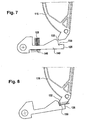
- FIG. 7 shows an alternative embodiment of the pawl 126 and the pivot lever 116 in the normal position of the pawl 126 with the container lid 112 closed.
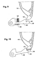
- the locking position of the pawl 126 is determined by the stop formed between the hooks 130 and 132, as shown in FIG FIG. 8 shown.
- An additional stop on the container 110 or an environmental part is not formed by the pawl 126 in this embodiment.
- FIG. 9 shows an alternative embodiment of the hooks 130 and 132 of the embodiments of FIGS. 7 and 8 ,
- the hooks 130 and 132 are here designed so that a smaller opening angle of the container lid 112 in the in the FIG. 10 shown locking position results.
Claims (18)
- Compartiment de rangement pour un véhicule automobile, avec- un récipient (110) et un couvercle de récipient (112) disposé de manière pivotante sur le récipient,- un levier de pivotement (116) disposé sur le couvercle de récipient,- un premier élément élastique (120), dont une première extrémité (122) est reliée au récipient et dont la seconde extrémité (118) est reliée au couvercle pivotant, de telle manière que le premier élément élastique exerce une force de fermeture et/ou un couple de fermeture sur le couvercle de récipient,- un élément de verrouillage (126), qui est monté de manière pivotante, de telle manière qu'il soit amené dans une position de verrouillage pour bloquer le couvercle pivotant en raison de son inertie en cas de collision du véhicule automobile,caractérisé en ce que
l'élément de verrouillage est monté de manière pivotante autour de la première extrémité du premier élément élastique, et en ce que le premier élément élastique est un ressort de point mort, dans lequel le ressort de point mort est conçu de façon à exercer la force de fermeture et/ou le couple de fermeture aussi longtemps qu'une position d'ouverture du couvercle de récipient ne dépasse pas un point mort (155). - Compartiment de rangement selon la revendication 1, dans lequel l'élément de verrouillage est réalisé en forme de cliquet.
- Compartiment de rangement selon la revendication 1 ou 2, dans lequel un tourillon (124) pour l'élément de verrouillage est disposé sur le récipient et le tourillon présente un évidement destiné à recevoir la première extrémité.
- Compartiment de rangement selon l'une quelconque des revendications précédentes, dans lequel la position de verrouillage est définie par une butée (160, 162) pour l'élément de verrouillage.
- Compartiment de rangement selon la revendication 4, dans lequel la butée est disposée sur une paroi du récipient et/ou sur une pièce voisine.
- Compartiment de rangement selon l'une quelconque des revendications précédentes, dans lequel le couvercle de récipient peut pivoter vers le haut, de telle manière qu'une ouverture supérieure du récipient soit accessible.
- Compartiment de rangement selon l'une quelconque des revendications précédentes, avec un deuxième élément élastique (128), qui est relié à l'élément de verrouillage, afin de maintenir l'élément de verrouillage hors de la position de verrouillage pendant le fonctionnement normal du véhicule automobile.
- Compartiment de rangement selon la revendication 7, dans lequel le deuxième élément élastique est relié à une branche (140) de l'élément de verrouillage.
- Compartiment de rangement selon la revendication 7 ou 8, dans lequel le deuxième élément élastique est un ressort de pression (128).
- Compartiment de rangement selon la revendication 7, 8 ou 9, dans lequel le premier système masse-ressort formé par le premier élément élastique et le couvercle de récipient est réalisé de telle manière que le couvercle de récipient reste fermé jusqu'à une première accélération, et dans lequel le deuxième système masse-ressort formé par l'élément de verrouillage et le deuxième élément élastique est réalisé de telle manière que l'élément de verrouillage reste dans sa position normale jusqu'à une deuxième accélération, la deuxième accélération étant inférieure à la première accélération.
- Compartiment de rangement selon la revendication 10, dans lequel la première accélération vaut entre 3 g et 5 g, de préférence environ 4, 3 g, et la deuxième accélération vaut entre 1 g et 3 g, de préférence environ 2,3 g.
- Compartiment de rangement selon la revendication 10 ou 11, dans lequel la différence entre la première et la deuxième accélération vaut au moins 1 g.
- Compartiment de rangement selon la revendication 12, dans lequel la différence entre la première et la deuxième accélération vaut au moins environ 2,3 g.
- Pièce d'habillage intérieur de véhicule automobile avec un compartiment de rangement selon l'une quelconque des revendications précédentes 1 à 13.
- Pièce d'habillage intérieur de véhicule automobile selon la revendication 14, dans laquelle cette pièce est un habillage intérieur de porte.
- Pièce d'habillage intérieur de véhicule automobile selon la revendication 14, dans laquelle la pièce est une console centrale.
- Pièce d'habillage intérieur de véhicule automobile selon la revendication 14, dans laquelle la pièce est un habillage intérieur de coffre à bagages.
- Porte de véhicule automobile avec un compartiment de rangement selon l'une quelconque des revendications précédentes 1 à 13.
Applications Claiming Priority (2)
| Application Number | Priority Date | Filing Date | Title |
|---|---|---|---|
| DE102005043593A DE102005043593B4 (de) | 2005-09-12 | 2005-09-12 | Staufach für ein Kraftfahrzeug |
| PCT/EP2006/063855 WO2007031351A1 (fr) | 2005-09-12 | 2006-07-04 | Compartiment de rangement pour un vehicule automobile |
Publications (2)
| Publication Number | Publication Date |
|---|---|
| EP1926633A1 EP1926633A1 (fr) | 2008-06-04 |
| EP1926633B1 true EP1926633B1 (fr) | 2009-09-16 |
Family
ID=36951554
Family Applications (1)
| Application Number | Title | Priority Date | Filing Date |
|---|---|---|---|
| EP06764053A Not-in-force EP1926633B1 (fr) | 2005-09-12 | 2006-07-04 | Compartiment de rangement pour un vehicule automobile |
Country Status (5)
| Country | Link |
|---|---|
| US (1) | US7845701B2 (fr) |
| EP (1) | EP1926633B1 (fr) |
| AT (1) | ATE442978T1 (fr) |
| DE (2) | DE102005043593B4 (fr) |
| WO (1) | WO2007031351A1 (fr) |
Cited By (2)
| Publication number | Priority date | Publication date | Assignee | Title |
|---|---|---|---|---|
| US11466479B2 (en) | 2020-03-23 | 2022-10-11 | Shanghai Yanfeng Jinqiao Automotive Trim Systems Co. Ltd. | Vehicle interior component |
| US11578515B2 (en) | 2018-05-04 | 2023-02-14 | Shanghai Yanfeng Jinqiao Automotive Trim Systems Co. Ltd. | Vehicle interior component |
Families Citing this family (31)
| Publication number | Priority date | Publication date | Assignee | Title |
|---|---|---|---|---|
| DE102008000802B4 (de) * | 2008-03-20 | 2012-05-10 | Faurecia Innenraum Systeme Gmbh | Vollautomatisches Staufach |
| KR100893442B1 (ko) * | 2008-05-07 | 2009-04-17 | 기아자동차주식회사 | 오픈 방지 구조를 갖는 차량용 트레이 |
| US20090284023A1 (en) * | 2008-05-16 | 2009-11-19 | Nifco Korea Inc. | Apparatus for preventing opening of a tray cover for an automobile |
| US8215688B2 (en) | 2008-10-15 | 2012-07-10 | Johnson Controls Technology Company | Vehicle floor console |
| DE102009012710A1 (de) * | 2009-03-11 | 2010-09-16 | Dr. Ing. H.C. F. Porsche Aktiengesellschaft | Kraftfahrzeug mit einem Ablagefach |
| DE202009004057U1 (de) | 2009-03-26 | 2010-08-19 | Peguform Gmbh | Klappfach für ein Kraftfahrzeug |
| DE102009058988A1 (de) | 2009-12-18 | 2011-06-22 | Dr. Ing. h.c. F. Porsche Aktiengesellschaft, 70435 | Kraftfahrzeug |
| DE102010021050B4 (de) | 2010-05-19 | 2015-06-11 | Audi Ag | Crashsicherung für ein Kfz-Bauteil |
| US8191953B2 (en) * | 2010-07-02 | 2012-06-05 | Ford Global Technologies, Llc | Integrated inertial lock and latch for console lid |
| US8388040B2 (en) * | 2011-03-30 | 2013-03-05 | GM Global Technology Operations LLC | Lock-out device for vehicle compartment with lid |
| DE102011051802B4 (de) * | 2011-07-13 | 2023-04-27 | Dr. Ing. H.C. F. Porsche Aktiengesellschaft | Staufachanordnung |
| US8961062B2 (en) | 2012-06-28 | 2015-02-24 | Ford Global Technologies, Llc | Inertial lockout mechanism |
| FR3004153B1 (fr) * | 2013-04-09 | 2017-01-13 | Faurecia Interieur Ind | Dispositif de ralentissement et de blocage d'un element par rapport a un autre element de vehicule |
| US9010830B2 (en) * | 2013-06-04 | 2015-04-21 | Charles L. Hanley | Shelving systems |
| US8979160B1 (en) | 2013-08-23 | 2015-03-17 | Ford Global Technologies, Llc | System and apparatus for providing a secure storage compartment |
| DE102014103792A1 (de) | 2014-03-20 | 2015-09-24 | Dr. Ing. H.C. F. Porsche Aktiengesellschaft | Verriegelung für eine schwenkbare Abdeckung in einem Fahrzeug |
| FR3021917A1 (fr) * | 2014-06-05 | 2015-12-11 | Peugeot Citroen Automobiles Sa | Coussin d'assise de siege de vehicule automobile adapte a la prehension du siege pour son installation dans l'habitacle. |
| DE102015110594A1 (de) * | 2015-07-01 | 2017-01-05 | Lisa Dräxlmaier GmbH | Armauflage für ein Fahrzeuginnenausstattungsteil |
| DE102015009585A1 (de) * | 2015-07-23 | 2017-01-26 | Audi Ag | Schwenkteil eines Fahrzeugs mit einem Öffnungs- und Schließmechanismus |
| FR3047211B1 (fr) * | 2016-01-28 | 2018-03-02 | Faurecia Interieur Industrie | Dispositif ouvrant comprenant un dispositif de blocage de securite |
| EP3458306B1 (fr) | 2016-05-18 | 2020-12-16 | Shanghai Yanfeng Jinqiao Automotive Trim Systems Co., Ltd. | Ensemble console pour intérieur de véhicule |
| DE102016006087A1 (de) * | 2016-05-20 | 2017-11-23 | Grammer Ag | Armlehne |
| DE102016214520A1 (de) * | 2016-08-05 | 2018-02-08 | Volkswagen Aktiengesellschaft | Armauflagenvorrichtung für ein Kraftfahrzeug |
| JP6577541B2 (ja) * | 2017-08-28 | 2019-09-18 | 豊田合成株式会社 | 両開き収納装置 |
| US11885171B2 (en) | 2018-12-04 | 2024-01-30 | Shanghai Yanfeng Jinqiao Automotive Trim Systems Co. Ltd. | Vehicle interior component |
| CN111497753B (zh) * | 2019-01-31 | 2021-06-22 | 长城汽车股份有限公司 | 车辆扶手箱和车辆 |
| US11572723B2 (en) | 2019-02-27 | 2023-02-07 | Shanghai Yanfeng Jinqiao Automotive Triim Systems Co. Ltd. | Vehicle interior component |
| US11318892B2 (en) * | 2019-04-19 | 2022-05-03 | Shanghai Yanfeng Jinqiao Automotive Trim Systems Co. Ltd. | Vehicle interior component |
| US11891018B2 (en) * | 2021-04-07 | 2024-02-06 | Toyoda Gosei Co., Ltd. | Storage compartments having inertia force closure mechanisms, console assemblies, and vehicles incorporating the same |
| US11873668B2 (en) * | 2021-04-23 | 2024-01-16 | Faurecia Interior Systems, Inc. | Vehicle interior panel with fall away door |
| DE102021212849A1 (de) | 2021-11-16 | 2023-05-17 | Volkswagen Aktiengesellschaft | Transporteinrichtung zur Anordnung in einem Transportmittel |
Family Cites Families (10)
| Publication number | Priority date | Publication date | Assignee | Title |
|---|---|---|---|---|
| US2621952A (en) * | 1950-03-31 | 1952-12-16 | Arnold F Gander | Flush type toggle latch |
| JPS606650U (ja) * | 1983-06-22 | 1985-01-18 | 本田技研工業株式会社 | 車両のインストルメントパネルに設けられる小物収納ボツクス |
| DE4130847C2 (de) * | 1991-09-17 | 1995-04-13 | Daimler Benz Ag | Verschlußkappe zum Verschließen eines Ablagefaches im Innenraum eines Kraftfahrzeuges |
| US6278676B1 (en) * | 1998-12-28 | 2001-08-21 | Prince Technology Corporation | Media player system for a vehicle |
| DE10027020B4 (de) * | 2000-05-31 | 2005-03-24 | Daimlerchrysler Ag | Mittelkonsole für Fahrzeuge |
| DE10200102B4 (de) * | 2002-01-03 | 2012-01-26 | Volkswagen Ag | Crashaktive Verriegelung von kinematischen Komponenten in einem Fahrzeuginnenraum |
| DE20311467U1 (de) * | 2003-07-25 | 2003-09-18 | Sarnatech Paulmann & Crone | Einbauteil als Innenausstattung von Kraftfahrzeugen |
| US7328825B2 (en) * | 2004-02-05 | 2008-02-12 | Dolores Kaiser | Secured dynamic storage compartment for vehicle door |
| DE202004003227U1 (de) | 2004-02-27 | 2004-06-24 | Ktsn Kunststofftechnik Sachsen Gmbh & Co. Kg | Verschlusseinheit für die Abdeckung einer Öffnung im Innenraum von Fahrzeugen |
| US7118151B2 (en) * | 2004-05-07 | 2006-10-10 | Ford Global Technologies, Llc | Automotive wet trunk with drain |
-
2005
- 2005-09-12 DE DE102005043593A patent/DE102005043593B4/de not_active Expired - Fee Related
-
2006
- 2006-07-04 DE DE502006004889T patent/DE502006004889D1/de active Active
- 2006-07-04 US US12/063,870 patent/US7845701B2/en not_active Expired - Fee Related
- 2006-07-04 EP EP06764053A patent/EP1926633B1/fr not_active Not-in-force
- 2006-07-04 WO PCT/EP2006/063855 patent/WO2007031351A1/fr active Application Filing
- 2006-07-04 AT AT06764053T patent/ATE442978T1/de active
Cited By (2)
| Publication number | Priority date | Publication date | Assignee | Title |
|---|---|---|---|---|
| US11578515B2 (en) | 2018-05-04 | 2023-02-14 | Shanghai Yanfeng Jinqiao Automotive Trim Systems Co. Ltd. | Vehicle interior component |
| US11466479B2 (en) | 2020-03-23 | 2022-10-11 | Shanghai Yanfeng Jinqiao Automotive Trim Systems Co. Ltd. | Vehicle interior component |
Also Published As
| Publication number | Publication date |
|---|---|
| ATE442978T1 (de) | 2009-10-15 |
| DE102005043593A1 (de) | 2007-03-29 |
| WO2007031351A1 (fr) | 2007-03-22 |
| DE502006004889D1 (de) | 2009-10-29 |
| EP1926633A1 (fr) | 2008-06-04 |
| US7845701B2 (en) | 2010-12-07 |
| DE102005043593B4 (de) | 2010-12-02 |
| US20090218842A1 (en) | 2009-09-03 |
Similar Documents
| Publication | Publication Date | Title |
|---|---|---|
| EP1926633B1 (fr) | Compartiment de rangement pour un vehicule automobile | |
| DE4130847C2 (de) | Verschlußkappe zum Verschließen eines Ablagefaches im Innenraum eines Kraftfahrzeuges | |
| DE19835364C2 (de) | Vorrichtung zum Einbau in einem Kraftwagen mit einem Ausziehteil | |
| DE102009045843A1 (de) | Griffvorrichtung | |
| DE102012016884A1 (de) | Verstellvorrichtung für ein schwenkbares Komfortelement, insbesondere für eine Armlehne eines Fahrzeugs | |
| DE102015114788A1 (de) | Behältnis mit einer Sicherheitsverriegelungsmechanik für ein Fahrzeug | |
| DE102011053395A1 (de) | Mittelkonsolenanordnung | |
| EP2636827A2 (fr) | Serrure de véhicule automobile | |
| DE102017216920A1 (de) | Türgriffeinrichtung für eine Tür eines Kraftfahrzeugs, Tür, Kraftfahrzeug | |
| DE10009291B4 (de) | Armlehne mit Staufach und verriegelbarem Deckel | |
| DE102009056538A1 (de) | Handhabe für eine Schließeinrichtung eines Kraftfahrzeugs | |
| WO2005028792A1 (fr) | Dispositif de verrouillage de securite destine a un contenant dans un vehicule | |
| DE102017103472A1 (de) | Kraftfahrzeugtürschloss | |
| EP1509663B1 (fr) | Dispositif de blocage securise pour recipient dans un vehicule | |
| EP1718828B1 (fr) | Unite de fermeture servant a recouvrir une ouverture menagee dans l'habitacle d'un vehicule | |
| DE102017127386A1 (de) | Kraftfahrzeugschloss | |
| EP2072717A1 (fr) | Unité de poignée à palette, en particulier pour un compartiment de dépôt/coffre de rangement d'un véhicule automobile | |
| DE102011115403A1 (de) | Sicherheitseinrichtung eines Fahrzeugs | |
| DE102011051328A1 (de) | Handhabe mit einer Massensperre, die bei einem Unfall verriegelbar ist | |
| DE4107219A1 (de) | Schloss mit hilfsmotor, insbesondere tuerschloss fuer ein kraftfahrzeug | |
| DE102020106126A1 (de) | Kraftfahrzeugschloss | |
| DE102008014767A1 (de) | Schutzeinrichtung an der Frontklappe eines Kraftfahrzeugs | |
| EP3990727B1 (fr) | Dispositif de verrouillage destiné à un récipient ou un couvercle, en particulier de véhicules automobiles, et pouvant être actionné entre une position fermée et une position ouverte | |
| DE102004063119B4 (de) | Sicherheitsverriegelung | |
| WO2017036452A1 (fr) | Serrure de porte de véhicule automobile |
Legal Events
| Date | Code | Title | Description |
|---|---|---|---|
| PUAI | Public reference made under article 153(3) epc to a published international application that has entered the european phase |
Free format text: ORIGINAL CODE: 0009012 |
|
| 17P | Request for examination filed |
Effective date: 20080414 |
|
| AK | Designated contracting states |
Kind code of ref document: A1 Designated state(s): AT BE BG CH CY CZ DE DK EE ES FI FR GB GR HU IE IS IT LI LT LU LV MC NL PL PT RO SE SI SK TR |
|
| GRAP | Despatch of communication of intention to grant a patent |
Free format text: ORIGINAL CODE: EPIDOSNIGR1 |
|
| GRAS | Grant fee paid |
Free format text: ORIGINAL CODE: EPIDOSNIGR3 |
|
| GRAA | (expected) grant |
Free format text: ORIGINAL CODE: 0009210 |
|
| AK | Designated contracting states |
Kind code of ref document: B1 Designated state(s): AT BE BG CH CY CZ DE DK EE ES FI FR GB GR HU IE IS IT LI LT LU LV MC NL PL PT RO SE SI SK TR |
|
| REG | Reference to a national code |
Ref country code: GB Ref legal event code: FG4D Free format text: NOT ENGLISH |
|
| REG | Reference to a national code |
Ref country code: CH Ref legal event code: EP |
|
| REG | Reference to a national code |
Ref country code: IE Ref legal event code: FG4D |
|
| REF | Corresponds to: |
Ref document number: 502006004889 Country of ref document: DE Date of ref document: 20091029 Kind code of ref document: P |
|
| PG25 | Lapsed in a contracting state [announced via postgrant information from national office to epo] |
Ref country code: SE Free format text: LAPSE BECAUSE OF FAILURE TO SUBMIT A TRANSLATION OF THE DESCRIPTION OR TO PAY THE FEE WITHIN THE PRESCRIBED TIME-LIMIT Effective date: 20090916 Ref country code: FI Free format text: LAPSE BECAUSE OF FAILURE TO SUBMIT A TRANSLATION OF THE DESCRIPTION OR TO PAY THE FEE WITHIN THE PRESCRIBED TIME-LIMIT Effective date: 20090916 Ref country code: LT Free format text: LAPSE BECAUSE OF FAILURE TO SUBMIT A TRANSLATION OF THE DESCRIPTION OR TO PAY THE FEE WITHIN THE PRESCRIBED TIME-LIMIT Effective date: 20090916 |
|
| LTIE | Lt: invalidation of european patent or patent extension |
Effective date: 20090916 |
|
| PG25 | Lapsed in a contracting state [announced via postgrant information from national office to epo] |
Ref country code: NL Free format text: LAPSE BECAUSE OF FAILURE TO SUBMIT A TRANSLATION OF THE DESCRIPTION OR TO PAY THE FEE WITHIN THE PRESCRIBED TIME-LIMIT Effective date: 20090916 Ref country code: LV Free format text: LAPSE BECAUSE OF FAILURE TO SUBMIT A TRANSLATION OF THE DESCRIPTION OR TO PAY THE FEE WITHIN THE PRESCRIBED TIME-LIMIT Effective date: 20090916 Ref country code: PL Free format text: LAPSE BECAUSE OF FAILURE TO SUBMIT A TRANSLATION OF THE DESCRIPTION OR TO PAY THE FEE WITHIN THE PRESCRIBED TIME-LIMIT Effective date: 20090916 Ref country code: SI Free format text: LAPSE BECAUSE OF FAILURE TO SUBMIT A TRANSLATION OF THE DESCRIPTION OR TO PAY THE FEE WITHIN THE PRESCRIBED TIME-LIMIT Effective date: 20090916 |
|
| NLV1 | Nl: lapsed or annulled due to failure to fulfill the requirements of art. 29p and 29m of the patents act | ||
| PG25 | Lapsed in a contracting state [announced via postgrant information from national office to epo] |
Ref country code: CY Free format text: LAPSE BECAUSE OF FAILURE TO SUBMIT A TRANSLATION OF THE DESCRIPTION OR TO PAY THE FEE WITHIN THE PRESCRIBED TIME-LIMIT Effective date: 20090916 |
|
| REG | Reference to a national code |
Ref country code: IE Ref legal event code: FD4D |
|
| PG25 | Lapsed in a contracting state [announced via postgrant information from national office to epo] |
Ref country code: RO Free format text: LAPSE BECAUSE OF FAILURE TO SUBMIT A TRANSLATION OF THE DESCRIPTION OR TO PAY THE FEE WITHIN THE PRESCRIBED TIME-LIMIT Effective date: 20090916 Ref country code: CZ Free format text: LAPSE BECAUSE OF FAILURE TO SUBMIT A TRANSLATION OF THE DESCRIPTION OR TO PAY THE FEE WITHIN THE PRESCRIBED TIME-LIMIT Effective date: 20090916 Ref country code: ES Free format text: LAPSE BECAUSE OF FAILURE TO SUBMIT A TRANSLATION OF THE DESCRIPTION OR TO PAY THE FEE WITHIN THE PRESCRIBED TIME-LIMIT Effective date: 20091227 Ref country code: EE Free format text: LAPSE BECAUSE OF FAILURE TO SUBMIT A TRANSLATION OF THE DESCRIPTION OR TO PAY THE FEE WITHIN THE PRESCRIBED TIME-LIMIT Effective date: 20090916 Ref country code: IS Free format text: LAPSE BECAUSE OF FAILURE TO SUBMIT A TRANSLATION OF THE DESCRIPTION OR TO PAY THE FEE WITHIN THE PRESCRIBED TIME-LIMIT Effective date: 20100116 Ref country code: PT Free format text: LAPSE BECAUSE OF FAILURE TO SUBMIT A TRANSLATION OF THE DESCRIPTION OR TO PAY THE FEE WITHIN THE PRESCRIBED TIME-LIMIT Effective date: 20100118 Ref country code: IE Free format text: LAPSE BECAUSE OF FAILURE TO SUBMIT A TRANSLATION OF THE DESCRIPTION OR TO PAY THE FEE WITHIN THE PRESCRIBED TIME-LIMIT Effective date: 20090916 |
|
| PG25 | Lapsed in a contracting state [announced via postgrant information from national office to epo] |
Ref country code: SK Free format text: LAPSE BECAUSE OF FAILURE TO SUBMIT A TRANSLATION OF THE DESCRIPTION OR TO PAY THE FEE WITHIN THE PRESCRIBED TIME-LIMIT Effective date: 20090916 |
|
| PLBE | No opposition filed within time limit |
Free format text: ORIGINAL CODE: 0009261 |
|
| STAA | Information on the status of an ep patent application or granted ep patent |
Free format text: STATUS: NO OPPOSITION FILED WITHIN TIME LIMIT |
|
| PG25 | Lapsed in a contracting state [announced via postgrant information from national office to epo] |
Ref country code: DK Free format text: LAPSE BECAUSE OF FAILURE TO SUBMIT A TRANSLATION OF THE DESCRIPTION OR TO PAY THE FEE WITHIN THE PRESCRIBED TIME-LIMIT Effective date: 20090916 |
|
| 26N | No opposition filed |
Effective date: 20100617 |
|
| PG25 | Lapsed in a contracting state [announced via postgrant information from national office to epo] |
Ref country code: GR Free format text: LAPSE BECAUSE OF FAILURE TO SUBMIT A TRANSLATION OF THE DESCRIPTION OR TO PAY THE FEE WITHIN THE PRESCRIBED TIME-LIMIT Effective date: 20091217 |
|
| BERE | Be: lapsed |
Owner name: FAURECIA INNENRAUM SYSTEME G.M.B.H. Effective date: 20100731 |
|
| PG25 | Lapsed in a contracting state [announced via postgrant information from national office to epo] |
Ref country code: MC Free format text: LAPSE BECAUSE OF NON-PAYMENT OF DUE FEES Effective date: 20100731 |
|
| REG | Reference to a national code |
Ref country code: CH Ref legal event code: PL |
|
| GBPC | Gb: european patent ceased through non-payment of renewal fee |
Effective date: 20100704 |
|
| PG25 | Lapsed in a contracting state [announced via postgrant information from national office to epo] |
Ref country code: IT Free format text: LAPSE BECAUSE OF FAILURE TO SUBMIT A TRANSLATION OF THE DESCRIPTION OR TO PAY THE FEE WITHIN THE PRESCRIBED TIME-LIMIT Effective date: 20090916 |
|
| PG25 | Lapsed in a contracting state [announced via postgrant information from national office to epo] |
Ref country code: CH Free format text: LAPSE BECAUSE OF NON-PAYMENT OF DUE FEES Effective date: 20100731 Ref country code: LI Free format text: LAPSE BECAUSE OF NON-PAYMENT OF DUE FEES Effective date: 20100731 |
|
| PG25 | Lapsed in a contracting state [announced via postgrant information from national office to epo] |
Ref country code: BE Free format text: LAPSE BECAUSE OF NON-PAYMENT OF DUE FEES Effective date: 20100731 |
|
| PG25 | Lapsed in a contracting state [announced via postgrant information from national office to epo] |
Ref country code: GB Free format text: LAPSE BECAUSE OF NON-PAYMENT OF DUE FEES Effective date: 20100704 |
|
| PG25 | Lapsed in a contracting state [announced via postgrant information from national office to epo] |
Ref country code: HU Free format text: LAPSE BECAUSE OF FAILURE TO SUBMIT A TRANSLATION OF THE DESCRIPTION OR TO PAY THE FEE WITHIN THE PRESCRIBED TIME-LIMIT Effective date: 20100317 Ref country code: LU Free format text: LAPSE BECAUSE OF NON-PAYMENT OF DUE FEES Effective date: 20100704 Ref country code: BG Free format text: LAPSE BECAUSE OF FAILURE TO SUBMIT A TRANSLATION OF THE DESCRIPTION OR TO PAY THE FEE WITHIN THE PRESCRIBED TIME-LIMIT Effective date: 20090916 |
|
| PG25 | Lapsed in a contracting state [announced via postgrant information from national office to epo] |
Ref country code: TR Free format text: LAPSE BECAUSE OF FAILURE TO SUBMIT A TRANSLATION OF THE DESCRIPTION OR TO PAY THE FEE WITHIN THE PRESCRIBED TIME-LIMIT Effective date: 20090916 |
|
| REG | Reference to a national code |
Ref country code: AT Ref legal event code: MM01 Ref document number: 442978 Country of ref document: AT Kind code of ref document: T Effective date: 20110704 |
|
| PG25 | Lapsed in a contracting state [announced via postgrant information from national office to epo] |
Ref country code: AT Free format text: LAPSE BECAUSE OF NON-PAYMENT OF DUE FEES Effective date: 20110704 |
|
| REG | Reference to a national code |
Ref country code: FR Ref legal event code: PLFP Year of fee payment: 11 |
|
| PGFP | Annual fee paid to national office [announced via postgrant information from national office to epo] |
Ref country code: DE Payment date: 20160622 Year of fee payment: 11 |
|
| REG | Reference to a national code |
Ref country code: FR Ref legal event code: PLFP Year of fee payment: 12 |
|
| REG | Reference to a national code |
Ref country code: DE Ref legal event code: R119 Ref document number: 502006004889 Country of ref document: DE |
|
| PG25 | Lapsed in a contracting state [announced via postgrant information from national office to epo] |
Ref country code: DE Free format text: LAPSE BECAUSE OF NON-PAYMENT OF DUE FEES Effective date: 20180201 |
|
| REG | Reference to a national code |
Ref country code: FR Ref legal event code: PLFP Year of fee payment: 13 |
|
| PGFP | Annual fee paid to national office [announced via postgrant information from national office to epo] |
Ref country code: FR Payment date: 20190621 Year of fee payment: 14 |
|
| PG25 | Lapsed in a contracting state [announced via postgrant information from national office to epo] |
Ref country code: FR Free format text: LAPSE BECAUSE OF NON-PAYMENT OF DUE FEES Effective date: 20200731 |