EP1926633B1 - Storage compartment for a motor vehicle - Google Patents
Storage compartment for a motor vehicle Download PDFInfo
- Publication number
- EP1926633B1 EP1926633B1 EP06764053A EP06764053A EP1926633B1 EP 1926633 B1 EP1926633 B1 EP 1926633B1 EP 06764053 A EP06764053 A EP 06764053A EP 06764053 A EP06764053 A EP 06764053A EP 1926633 B1 EP1926633 B1 EP 1926633B1
- Authority
- EP
- European Patent Office
- Prior art keywords
- storage compartment
- motor vehicle
- container
- container lid
- locking element
- Prior art date
- Legal status (The legal status is an assumption and is not a legal conclusion. Google has not performed a legal analysis and makes no representation as to the accuracy of the status listed.)
- Not-in-force
Links
Images


Classifications
-
- E—FIXED CONSTRUCTIONS
- E05—LOCKS; KEYS; WINDOW OR DOOR FITTINGS; SAFES
- E05B—LOCKS; ACCESSORIES THEREFOR; HANDCUFFS
- E05B77/00—Vehicle locks characterised by special functions or purposes
- E05B77/02—Vehicle locks characterised by special functions or purposes for accident situations
- E05B77/04—Preventing unwanted lock actuation, e.g. unlatching, at the moment of collision
- E05B77/06—Preventing unwanted lock actuation, e.g. unlatching, at the moment of collision by means of inertial forces
-
- B—PERFORMING OPERATIONS; TRANSPORTING
- B60—VEHICLES IN GENERAL
- B60R—VEHICLES, VEHICLE FITTINGS, OR VEHICLE PARTS, NOT OTHERWISE PROVIDED FOR
- B60R7/00—Stowing or holding appliances inside vehicle primarily intended for personal property smaller than suit-cases, e.g. travelling articles, or maps
- B60R7/04—Stowing or holding appliances inside vehicle primarily intended for personal property smaller than suit-cases, e.g. travelling articles, or maps in driver or passenger space, e.g. using racks
-
- E—FIXED CONSTRUCTIONS
- E05—LOCKS; KEYS; WINDOW OR DOOR FITTINGS; SAFES
- E05B—LOCKS; ACCESSORIES THEREFOR; HANDCUFFS
- E05B83/00—Vehicle locks specially adapted for particular types of wing or vehicle
- E05B83/28—Locks for glove compartments, console boxes, fuel inlet covers or the like
- E05B83/32—Locks for glove compartments, console boxes, fuel inlet covers or the like for console boxes, e.g. between passenger seats
Definitions
- the invention relates to a storage compartment for a motor vehicle and a motor vehicle interior trim part, such as a door trim panel, a center console and a trunk interior trim, and a motor vehicle door with a storage compartment.
- a storage compartment for the interior of a motor vehicle must ensure not only the ease of use and high reliability. In the event of an accident or crash, it must not happen that the storage compartment opens automatically. Otherwise, objects stored in the storage compartment could be thrown out of the storage compartment with considerable acceleration, as a result of which a risk and possibly injury to persons inside the motor vehicle may result.
- US 4,552,399 A shows a storage compartment according to the preamble of claim 1.
- U1 is a closure unit for the cover of an opening in the interior of vehicles known.
- the locking unit has a closing element which is clawed from two sides. By engaging in a locking latch locking lug a rocker locking latch of the locking unit are securely locked in a final closing position. Without actuating an opening handle thereby an automatic opening is excluded.
- the crash barrier is designed to prevent the drawer of the center console is thrown backwards out of the center console due to their inertia in a crash of the motor vehicle.
- the triggering of the crash barrier is based solely on the inertial forces of the components. The triggering of the crash lock begins only when the drawer begins to move out.
- the lock has a drive for a locking member, which is controlled by an acceleration sensor of an airbag control unit.
- the invention is based on the object to provide an improved storage compartment for a motor vehicle, and a motor vehicle interior trim part, such as a door trim panel, a center console and a trunk interior trim, and a motor vehicle door with such a storage compartment.
- the invention provides a storage compartment for a motor vehicle, which has a container with a container lid pivotally mounted on the container. On the container lid a pivot lever is arranged.
- An elastic element i. a dead center spring is connected at its first end to the container and at its second end to the pivot lever.
- the dead center exerts thereby a closing force or a closing moment on the container lid, as long as an open position of the container lid does not exceed a dead center.
- a dead center spring and an elastic band or the like can be used to keep the container lid closed during normal operation.
- the closing force or the closing moment can be exerted directly on the container lid or indirectly on a locking mechanism of the container lid, so that it keeps the container lid closed.
- the invention is particularly advantageous because the locking element is pivotally mounted about the first end of the resilient member, ie the dead center spring, with the first end connected to the container. This allows a construction which is at the same time particularly compact and also functionally safe under high acceleration forces.
- the storage compartment has a locking element which is pivotally mounted, so that it is brought due to its inertia in a collision of the motor vehicle in a Verrieglungsposition for locking the pivot lever.
- the present invention allows a structurally compact design of a storage compartment with a crash lock. This is made possible by the fact that the locking element locked in its Verrieglungsposition the normally required in normal operation pivot lever.
- the Verrieglungselement is pivotally mounted about the first end of the dead center. This allows a particularly compact structural design.
- the locking element is formed latch-shaped.
- the locking element at its end facing away from the pivot axis has a hook-shaped configuration in order to be able to engage in the locking position in a corresponding hook-shaped design of the pivot lever.
- the locking position of the locking element is defined by the hook-shaped design of the pivot lever and / or by one or more stops for the Verrieglungselement.
- a bearing pin for the Verrieglungselement is arranged on the container.
- This journal forms the pivot axis for the Verrieglungselement.
- the journal has a recess for receiving the first end of the dead center spring, which extends along the pivot axis into the journal.
- the container lid is to be opened upwards.
- the container is integrated in a door inner panel, so that a storage compartment is created, for example in the driver's door or passenger door.
- the locking element is connected to an elastic element.
- the elastic element is used to keep the locking element during normal operation of the motor vehicle outside the locking position, so that during normal operation of the motor vehicle, the container lid can be opened to place objects in the storage compartment or to remove therefrom.
- the locking element is moved due to its inertia against the spring force exerted by the elastic element in the locking position.
- the elastic member also serves as a rattle guard to hold the locking member in its normal position when the motor vehicle is traveling on a rough road or through potholes.
- the elastic element acts on a leg of the locking element.
- a torque is exerted on the locking element.
- an acceleration acting on the locking element acceleration is required, which is so large that this torque is overcome.
- the elastic element is a compression spring.
- the mass-spring system formed from the dead center spring and the container lid is designed so that the container lid remains closed until a first acceleration.
- the second mass-spring system formed from the locking element and the elastic element is designed so that the locking element remains in its normal position until a second acceleration, wherein the second acceleration is smaller than the first acceleration.
- the locking element When a large acceleration of e.g. 40 g, for example, when the motor vehicle strikes in a rollover with the roof down on the road, this ensures that the locking element has already reached its locking position before the container lid can open. In other words, therefore, the mass-spring system formed from the locking element and the elastic element precedes the mass-spring system formed from the dead center spring and the container lid. Depending on the choice of geometries and / or the masses and the spring stiffnesses, this can lead to a small opening of the container lid, in which, however, no objects can fall out of the container.
- the locking position is fixed by appropriate stops. Alternatively, it is also possible that the locking position results from the positions of the locking element and the lever of the container lid when both meet.
- the first acceleration is between three and five times the gravitational acceleration (g), in particular about 4.3 g, while the second acceleration is between 1 g and 3 g, preferably about 2.3 g.
- the difference between the first and second accelerations is at least 1 g, preferably about 2.3 g.
- the present invention relates to a motor vehicle interior trim part with an integrated storage space, such as a storage compartment, which has a crash lock according to the invention.
- the motor vehicle interior trim part may be, for example, a door trim panel, a center console or a trunk interior trim.
- the invention relates to a motor vehicle door with an integrated storage compartment, which has a crash lock according to the invention.
- FIG. 1 shows a motor vehicle door 100 with a window 102 and arranged below a door railing 104 storage compartment 106.
- the storage compartment 106 is part of the door inner lining of the motor vehicle door 100.
- the storage compartment 106 is in Direction of travel through a switch panel 108 completed in the FIG. 1 indicated by dashed lines.
- the switch panel 108 serves to accommodate various operating elements, such as for actuating the window regulator for the window 102.
- the storage compartment 106 has a container 110 which has a container opening accessible from above.
- the container opening of the container 110 is closed by a container lid 112.
- the container lid 112 is pivotally mounted on the container 110 and can be pivoted by a user in the direction of arrow 114 to put through the then accessible container opening an object in the storage space formed by the container 110 or to remove this.
- the container lid 112 has a pivot lever 116 which is fixedly connected to the container lid 112.
- the container lid 112 and the pivot lever 116 may be a single component, such as a plastic molded part.
- a dead center spring 120 On the pivot lever 116 engages an end 118 of a dead center spring 120 which is connected at its other end 122 to the container 110.
- the dead center spring 120 By the dead center spring 120 is in the in the FIG. 1 shown position of the container lid 112 exerted a closing force or a closing moment on the container lid 112, which can be overcome by operating the container lid 112 in the direction of arrow 114 by a user to open the container lid 112.
- the dead center spring 120 applies an opening force or opening moment to the container lid 112 to assist the opening movement and then to keep the container lid 112 open.
- This Tornungsmoment can be overcome by the user by pressing the container lid opposite to the arrow 114 to close the container lid 112 again.
- the container 110 has a journal 124 having a longitudinal recess which receives the end 122 of the dead center spring 120.
- a pawl 126 is pivotally mounted on the bearing pin 124. The pawl 126 is in their in the FIG. 1 shown normal position held by a compression spring 128.
- the pawl 126 has at its end facing away from the bearing pin 124 a hook 130 which is adapted to engage in a corresponding formed at the end of the pivot lever 116 hook 132 in a locking position.
- FIG. 2 shows a side view of the storage compartment 106 of FIG. 1 with closed container lid 112 and in the normal position of the pawl 126, that is, during normal operation of the motor vehicle.
- the FIG. 2 shows a hinge 134 with the container lid 112 is pivotally mounted on the container 110.
- the end 118 of the dead center spring is angled, so that the end 118 can not slip out of the through hole 136.
- FIG. 2 also shows the location of the centroid 138 of the pawl 126.
- FIG. 3 shows the storage compartment 106 in a front view.
- the compression spring 128 is arranged in the embodiment shown here so that its force application point 139 is located on the leg 140 of the pawl 126 approximately on the line 142 which extends in the vertical direction through the center of gravity 138.
- a spring force 144 is exerted on the force application point 139, so that the pawl 126 is pressed against a stop 146 which is formed on the container 110.
- the dead center spring 120 whose end 122 is inserted into the recess of the bearing journal 124, is under a bias, so that the dead center spring 120 exerts a closing force or a closing moment on the container lid 112.
- the magnitude of this closing moment results from the distance 150 between the line 152 connecting the pivot axis of the pawl 126 and the through hole 136 to the line 154 extending parallel to the line 152 through the pivot axis of the container lid 112.
- the dead center spring 120 applies an opening moment to the container lid 112 instead of a closing moment to assist the opening movement of the container lid 112 to keep it open.
- FIG. 4 shows the storage compartment 106 in a locking position of the pawl 126, which has taken this due to an impact.
- the dead center spring 120 and the compression spring 128 in the FIG. 4 not shown.
- an acceleration force 156 acts on the center of gravity 138 of the pawl 126, which is directed against the spring force 144.
- a corresponding acceleration force 158 also acts on the container lid 112.
- the spring force 144 and the mass of the pawl 126 are chosen so that the holding force caused by the spring force 144, which holds the pawl 126 in its normal position, is already overcome at a lower acceleration than that of the dead center spring 120 on the container lid 112 exercised Closing torque is the case. Thereby rushes through the pawl 126 and the compression spring 128 (in the FIG. 4 the sake of clarity, not shown) mass-spring system formed by the dead center 120 and the container lid 112 formed mass-spring system, whereby the pawl 126 their in the FIG. 4 shown locked position, as long as the container lid 112 has not or only slightly opened.
- the hooks 130 and 132 engage each other so that the container lid 112 is locked by the pawl 126.
- the pivoting movement of the pawl 126 into its locking position is limited either by the interlocking hooks 130 and 132 and / or by a stop 160 formed on the wall of the container 110 and / or by a stop 162, the surrounding part of the motor vehicle door lining with a nose 164 of the pawl 126 may form.
- the container lid 112 Due to the lead of the spring-mass system, which is formed from the pawl 126 and the compression spring 138, the container lid 112, as soon as it starts to move, locked, and thereby practically not or only slightly opened, so that no or at least no larger objects can fall out of the container when the vehicle hits the roof down on the road.
- the container lid 112 is opened by at most 10 °, for example by about 7 °, 3.75 ° or 1.5 °, depending on the selected spring forces and mass ratios and the geometry of the hooks 130, 132 and optionally the stops 160, 162 If the compression spring 128 has a small spring constant and the spring force 144 is correspondingly low, a configuration of the storage compartment 106 is possible in which the container lid 112 in the locked position is not or almost not open.
- the container lid 112 After the degradation of the acceleration forces 156 and 158, that is, after the completed impact, the container lid 112 is completely closed again due to the closing torque exerted by the dead center spring 120. Preferably move the hooks 130, 132 apart, so that the pawl 126 pivots back to its normal position. This makes it possible to open the container lid 112 nondestructively even after such an impact.
- the spring-mass system formed by the pawl 126 and the compression spring 128 is dimensioned so that when accelerated in the direction of the acceleration force 156 of 1 g to 3 g, the holding torque caused by the compression spring 128 is overcome.
- the mass spring system formed by the dead spring 120 and the container lid 112 is dimensioned so that the closing moment caused by the dead center spring 120 is overcome only at a higher acceleration of, for example, between 3 g and 5 g.
- the difference between these accelerations is at least 1 g, preferably about 2.3 g.
- the container lid 112 has a mass of about 360 g and the dead center 120 a closing moment of 580th Nmm on the container lid 112 exerts.
- a dimensioning results in that, with an acceleration of 2.3 g, the holding moment caused by the compression spring 128 is overcome and, with an acceleration of 4.3 g, the closing moment caused by the dead center spring 120 is overcome.
- FIG. 5 shows a detailed view of the pawl 126 and the pivot lever 116 of the embodiments of Figure 1 to 4 , In the normal position of the pivot lever 116th In the in the FIG. 5 shown position, the container lid 112 is closed.
- FIG. 6 shows the pawl 126 in its locking position.
- the locking position of the pawl 126 is determined by the stops 160 and / or 162.
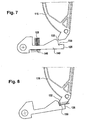
- FIG. 7 shows an alternative embodiment of the pawl 126 and the pivot lever 116 in the normal position of the pawl 126 with the container lid 112 closed.
- the locking position of the pawl 126 is determined by the stop formed between the hooks 130 and 132, as shown in FIG FIG. 8 shown.
- An additional stop on the container 110 or an environmental part is not formed by the pawl 126 in this embodiment.
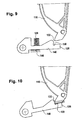
- FIG. 9 shows an alternative embodiment of the hooks 130 and 132 of the embodiments of FIGS. 7 and 8 ,
- the hooks 130 and 132 are here designed so that a smaller opening angle of the container lid 112 in the in the FIG. 10 shown locking position results.
Abstract
Description
Die Erfindung betrifft ein Staufach für ein Kraftfahrzeug sowie ein Kraftfahrzeug-Innenverkleidungsteil, wie zum Beispiel eine Tür-Innenverkleidung, eine Mittelkonsole und eine Kofferraum-Innenverkleidung, und eine Kraftfahrzeugtür mit einem Staufach.The invention relates to a storage compartment for a motor vehicle and a motor vehicle interior trim part, such as a door trim panel, a center console and a trunk interior trim, and a motor vehicle door with a storage compartment.
Ein Staufach für den Innenraum eines Kraftfahrzeugs muss neben dem Bedienkomfort auch eine hohe Funktionssicherheit gewährleisten. Bei einem Unfall oder Crash darf es nicht dazu kommen, dass sich das Staufach selbsttätig öffnet. In dem Staufach abgelegte Gegenstände könnten sonst mit erheblicher Beschleunigung aus dem Staufach geschleudert werden, wodurch es zu einer Gefährdung und gegebenenfalls Verletzung von im Innenraum des Kraftfahrzeugs befindlichen Personen kommen kann.A storage compartment for the interior of a motor vehicle must ensure not only the ease of use and high reliability. In the event of an accident or crash, it must not happen that the storage compartment opens automatically. Otherwise, objects stored in the storage compartment could be thrown out of the storage compartment with considerable acceleration, as a result of which a risk and possibly injury to persons inside the motor vehicle may result.
Aus der
Aus der
Aus der
Aus der
Aus der
Der Erfindung liegt dem gegenüber die Aufgabe zu Grunde ein verbessertes Staufach für ein Kraftfahrzeug zu schaffen, sowie ein Kraftfahrzeug-Innenverkleidungsteil, wie zum Beispiel eine Tür-Innenverkleidung, eine Mittelkonsole und eine Kofferraum-Innenverkleidung, und eine Kraftfahrzeugtür mit einem solchen Staufach.The invention is based on the object to provide an improved storage compartment for a motor vehicle, and a motor vehicle interior trim part, such as a door trim panel, a center console and a trunk interior trim, and a motor vehicle door with such a storage compartment.
Die der Erfindung zu Grunde liegenden Aufgaben werden jeweils mit den Merkmalen der unabhängigen Patentansprüche gelöst. Bevorzugte Ausführungsformen der Erfindung sind in den abhängigen Ansprüchen angegeben.The objects underlying the invention are each achieved with the features of the independent claims. Preferred embodiments of the invention are indicated in the dependent claims.
Durch die Erfindung wird ein Staufach für ein Kraftfahrzeug geschaffen, das einen Behälter mit einem an dem Behälter schwenkbar angeordneten Behälterdeckel aufweist. An dem Behälterdeckel ist ein Schwenkhebel angeordnet. Ein elastisches Element, d.h. eine Totpunktfeder, ist mit dessen ersten Ende mit dem Behälter und mit dessen zweiten Ende mit dem Schwenkhebel verbunden. Die Totpunktfeder übt dadurch eine Schließkraft bzw. ein Schließmoment auf den Behälterdeckel aus, solange eine Öffnungsstellung des Behälterdeckels einen Totpunkt nicht überschreitet. Statt einer Totpunktfeder kann auch ein elastisches Band oder dergleichen verwendet werden, um den Behälterdeckel im Normalbetrieb geschlossen zu halten. Die Schließkraft bzw. das Schließmoment kann dabei unmittelbar auf den Behälterdeckel oder mittelbar auf einen Verriegelungsmechanismus des Behälterdeckels ausgeübt werden, so dass dieser den Behälterdeckel geschlossen hält.The invention provides a storage compartment for a motor vehicle, which has a container with a container lid pivotally mounted on the container. On the container lid a pivot lever is arranged. An elastic element, i. a dead center spring is connected at its first end to the container and at its second end to the pivot lever. The dead center exerts thereby a closing force or a closing moment on the container lid, as long as an open position of the container lid does not exceed a dead center. Instead of a dead center spring and an elastic band or the like can be used to keep the container lid closed during normal operation. The closing force or the closing moment can be exerted directly on the container lid or indirectly on a locking mechanism of the container lid, so that it keeps the container lid closed.
Die Erfindung ist besonders vorteilhaft, da das Verriegelungselement um das erste Ende des elastischen Elements, d.h. der Totpunktfeder, schwenkbar gelagert ist, wobei das erste Ende mit dem Behälter verbunden ist. Dies ermöglicht eine zugleich besonders kompakte und auch bei hohen Beschleunigungskräften sicher funktionsfähige Konstruktion.The invention is particularly advantageous because the locking element is pivotally mounted about the first end of the resilient member, ie the dead center spring, with the first end connected to the container. This allows a construction which is at the same time particularly compact and also functionally safe under high acceleration forces.
Das Staufach hat ein Verriegelungselement, welches schwenkbar gelagert ist, so dass es aufgrund seiner Massenträgheit bei einem Aufprall des Kraftfahrzeugs in eine Verrieglungsposition zur Arretierung des Schwenkhebels gebracht wird.The storage compartment has a locking element which is pivotally mounted, so that it is brought due to its inertia in a collision of the motor vehicle in a Verrieglungsposition for locking the pivot lever.
Die vorliegende Erfindung ermöglicht also eine konstruktiv kompakte Ausgestaltung eines Staufachs mit einer Crash-Verrieglung. Dies wird dadurch ermöglicht, dass das Verriegelungselement in seiner Verrieglungsposition den im Normalbetrieb ohnehin benötigten Schwenkhebel arretiert.Thus, the present invention allows a structurally compact design of a storage compartment with a crash lock. This is made possible by the fact that the locking element locked in its Verrieglungsposition the normally required in normal operation pivot lever.
Nach einer Ausführungsform der Erfindung ist das Verrieglungselement um das erste Ende der Totpunktfeder schwenkbar gelagert. Dies ermöglicht eine besonders kompakte konstruktive Ausgestaltung.According to one embodiment of the invention, the Verrieglungselement is pivotally mounted about the first end of the dead center. This allows a particularly compact structural design.
Nach einer Ausführungsform der Erfindung ist das Verriegelungselement klinkenförmig ausgebildet. Beispielsweise hat das Verrieglungselement an seinem der Schwenkachse abgewandten Ende eine hakenförmige Ausbildung, um in der Verrieglungsposition in eine entsprechende hakenförmige Ausbildung des Schwenkhebels eingreifen zu können. Die Verriegelungsposition des Verriegelungselements wird dabei durch die hakenförmige Ausbildung des Schwenkhebels und / oder durch ein oder mehrere Anschläge für das Verrieglungselement definiert.According to one embodiment of the invention, the locking element is formed latch-shaped. For example, the locking element at its end facing away from the pivot axis has a hook-shaped configuration in order to be able to engage in the locking position in a corresponding hook-shaped design of the pivot lever. The locking position of the locking element is defined by the hook-shaped design of the pivot lever and / or by one or more stops for the Verrieglungselement.
Nach einer Ausführungsform der Erfindung ist an dem Behälter ein Lagerzapfen für das Verrieglungselement angeordnet. Dieser Lagerzapfen bildet die Schwenkachse für das Verrieglungselement. Der Lagerzapfen hat eine Ausnehmung zur Aufnahme des ersten Endes der Totpunktfeder, welches entlang der Schwenkachse in den Lagerzapfen hinein verläuft.According to one embodiment of the invention, a bearing pin for the Verrieglungselement is arranged on the container. This journal forms the pivot axis for the Verrieglungselement. The journal has a recess for receiving the first end of the dead center spring, which extends along the pivot axis into the journal.
Nach einer weiteren Ausführungsform der Erfindung ist der Behälterdeckel nach oben zu öffnen. Beispielsweise ist der Behälter in eine Tür-Innenverkleidung integriert, so dass ein Staufach beispielsweise in der Fahrertür oder Beifahrertür geschaffen wird.According to a further embodiment of the invention, the container lid is to be opened upwards. For example, the container is integrated in a door inner panel, so that a storage compartment is created, for example in the driver's door or passenger door.
Nach einer Ausführungsform der Erfindung ist das Verriegelungselement mit einem elastischen Element verbunden. Das elastische Element dient dazu, das Verriegelungselement bei Normalbetrieb des Kraftfahrzeugs außerhalb der Verriegelungsposition zu halten, so dass beim Normalbetrieb des Kraftfahrzeugs der Behälterdeckel geöffnet werden kann, um Gegenstände in das Staufach zu legen oder aus diesem zu entnehmen. Bei einer Beschleunigung, die beim Normalbetrieb des Kraftfahrzeugs üblicherweise nicht vorkommt, wird das Verriegelungselement aufgrund dessen Massenträgheit entgegen der von dem elastischen Element ausgeübten Federkraft in die Verriegelungsposition bewegt.According to one embodiment of the invention, the locking element is connected to an elastic element. The elastic element is used to keep the locking element during normal operation of the motor vehicle outside the locking position, so that during normal operation of the motor vehicle, the container lid can be opened to place objects in the storage compartment or to remove therefrom. In an acceleration that usually does not occur during normal operation of the motor vehicle, the locking element is moved due to its inertia against the spring force exerted by the elastic element in the locking position.
Das elastische Element dient ferner als Klapperschutz, um das Verriegelungselement in seiner Normalposition zu halten, wenn das Kraftfahrzeug auf einer unebenen Straße oder durch Schlaglöcher fährt.The elastic member also serves as a rattle guard to hold the locking member in its normal position when the motor vehicle is traveling on a rough road or through potholes.
Nach einer Ausführungsform der Erfindung wirkt das elastische Element auf einen Schenkel des Verriegelungselements. Dadurch wird auf das Verriegelungselement ein Drehmoment ausgeübt. Um das Verriegelungselement in Bewegung zu setzen, ist eine auf das Verriegelungselement wirkende Beschleunigung erforderlich, die so groß ist, dass dieses Drehmoment überwunden wird.According to one embodiment of the invention, the elastic element acts on a leg of the locking element. As a result, a torque is exerted on the locking element. In order to set the locking element in motion, an acceleration acting on the locking element acceleration is required, which is so large that this torque is overcome.
Bei einer Ausführungsform der Erfindung handelt es sich bei dem elastischen Element um eine Druckfeder.In one embodiment of the invention, the elastic element is a compression spring.
Nach einer weiteren Ausführungsform der Erfindung ist das aus der Totpunktfeder und dem Behälterdeckel gebildete Masse-Feder-System so ausgebildet, dass der Behälterdeckel bis zu einer ersten Beschleunigung geschlossen bleibt. Das aus dem Verriegelungselement und dem elastischen Element gebildete zweite Masse-Feder-System ist dagegen so ausgebildet, dass das Verriegelungselement bis zu einer zweiten Beschleunigung in seiner Normalposition bleibt, wobei die zweite Beschleunigung kleiner als die erste Beschleunigung ist.According to a further embodiment of the invention, the mass-spring system formed from the dead center spring and the container lid is designed so that the container lid remains closed until a first acceleration. The second mass-spring system formed from the locking element and the elastic element, however, is designed so that the locking element remains in its normal position until a second acceleration, wherein the second acceleration is smaller than the first acceleration.
Beim Auftreten einer großen Beschleunigung von z.B. 40 g, beispielsweise wenn das Kraftfahrzeug bei einem Überschlag mit dem Dach nach unten auf die Straße aufschlägt, ist dadurch sichergestellt, dass das Verriegelungselement bereits seine Verriegelungsposition erreicht hat, bevor sich der Behälterdeckel öffnen kann. Mit anderen Worten eilt also das aus dem Verriegelungselement und dem elastischen Element gebildete Masse-Feder-System dem aus der Totpunktfeder und dem Behälterdeckel gebildeten Masse-Feder-System vor. Dabei kann es je nach der Wahl der Geometrien und/oder der Massen und der Federsteifigkeiten zu einer geringen Öffnung des Behälterdeckels kommen, bei der aber noch keine Gegenstände aus dem Behälter herausfallen können. Beispielsweise ist die Verriegelungsposition durch entsprechende Anschläge fest vorgegeben. Alternativ ist es auch möglich, dass sich die Verriegelungsposition aus den Stellungen des Verriegelungselements und des Hebels des Behälterdeckels ergibt, wenn beide aufeinander treffen.When a large acceleration of e.g. 40 g, for example, when the motor vehicle strikes in a rollover with the roof down on the road, this ensures that the locking element has already reached its locking position before the container lid can open. In other words, therefore, the mass-spring system formed from the locking element and the elastic element precedes the mass-spring system formed from the dead center spring and the container lid. Depending on the choice of geometries and / or the masses and the spring stiffnesses, this can lead to a small opening of the container lid, in which, however, no objects can fall out of the container. For example, the locking position is fixed by appropriate stops. Alternatively, it is also possible that the locking position results from the positions of the locking element and the lever of the container lid when both meet.
Nach einer Ausführungsform der Erfindung beträgt die erste Beschleunigung zwischen dem Drei- und Fünffachen der Erdbeschleunigung (g), insbesondere ca. 4,3 g, während die zweite Beschleunigung zwischen 1 g und 3 g, vorzugsweise ca. 2,3 g beträgt.According to one embodiment of the invention, the first acceleration is between three and five times the gravitational acceleration (g), in particular about 4.3 g, while the second acceleration is between 1 g and 3 g, preferably about 2.3 g.
Nach einer Ausführungsform der Erfindung beträgt die Differenz zwischen den ersten und zweiten Beschleunigungen mindestens 1 g, vorzugsweise ca. 2,3 g.According to one embodiment of the invention, the difference between the first and second accelerations is at least 1 g, preferably about 2.3 g.
In einem weiteren Aspekt betrifft die vorliegende Erfindung ein Kraftfahrzeug-Innenverkleidungsteil mit einem integrierten Stauraum, wie zum Beispiel einem Ablagefach, welches eine erfindungsgemäße Crash-Verriegelung aufweist. Bei dem Kraftfahrzeug-Innenverkleidungsteil kann es sich beispielsweise um eine Tür-Innenverkleidung, eine Mittelkonsole oder eine Kofferraum-Innenverkleidung handeln.In a further aspect, the present invention relates to a motor vehicle interior trim part with an integrated storage space, such as a storage compartment, which has a crash lock according to the invention. The motor vehicle interior trim part may be, for example, a door trim panel, a center console or a trunk interior trim.
In einem weiteren Aspekt betrifft die Erfindung eine Kraftfahrzeug-Tür mit einem integrierten Staufach, welches eine erfindungsgemäße Crash-Verriegelung aufweist.In a further aspect, the invention relates to a motor vehicle door with an integrated storage compartment, which has a crash lock according to the invention.
Im weiteren werden bevorzugte Ausführungsformen der Erfindung mit Bezugnahme auf die Zeichnungen näher erläutert. Es zeigen:
- Figur 1
- eine perspektivische Darstellung einer Ausführungsform eines erfindungsgemäßen Staufachs, welches als Ablagefach in der Tür-Innenverkleidung der Fahrertür eines Kraftfahrzeugs ausgebildet ist,
- Figur 2
- eine seitliche Ansicht eines vorderen Abschnitts des Ablagefachs,
- Figur 3
- eine Frontalansicht des Ablagefachs der
Figur 1 , - Figur 4
- die Ansicht des Ablagefachs der
Figur 3 , wobei sich das Verriegelungselement in seiner Verriegelungsposition befindet, - Figur 5
- eine Detailansicht des Verriegelungselements und des Schwenkhebels der Ausführungsformen gemäß
Figur 1 bis 4 in Normalposition, - Figur 6
- die Ansicht gemäß
Figur 5 in Verriegelungsposition, - Figur 7
- eine alternative Ausführungsform des Verriegelungselements und des Schwenkhakens in Normalposition,
- Figur 8
- die Ansicht der
Figur 7 in Verriegelungsposition, - Figur 9
- eine weitere Ausführungsform des Verriegelungselements und des Schwenkhakens in Normalposition,
- Figur 10
- die Ansicht der
Figur 9 in Verriegelungsposition.
- FIG. 1
- a perspective view of an embodiment of a storage compartment according to the invention, which is designed as a storage compartment in the door inner lining of the driver's door of a motor vehicle,
- FIG. 2
- a side view of a front portion of the storage compartment,
- FIG. 3
- a frontal view of the storage compartment of the
FIG. 1 . - FIG. 4
- the view of the storage compartment of the
FIG. 3 with the locking element in its locking position, - FIG. 5
- a detailed view of the locking element and the pivot lever of the embodiments according to
Figure 1 to 4 in normal position, - FIG. 6
- the view according to
FIG. 5 in locking position, - FIG. 7
- an alternative embodiment of the locking element and the pivot hook in normal position,
- FIG. 8
- the view of
FIG. 7 in locking position, - FIG. 9
- a further embodiment of the locking element and the pivoting hook in the normal position,
- FIG. 10
- the view of
FIG. 9 in locking position.
Die
Das Ablagefach 106 hat einen Behälter 110, der eine von oben zugängliche Behälteröffnung hat. Die Behälteröffnung des Behälters 110 wird durch einen Behälterdeckel 112 geschlossen. Der Behälterdeckel 112 ist schwenkbar an dem Behälter 110 gelagert und kann durch einen Benutzer in Pfeilrichtung 114 aufgeschwenkt werden, um durch die dann zugängliche Behälteröffnung einen Gegenstand in den durch den Behälter 110 gebildeten Stauraum zu legen oder diesem zu entnehmen.The
Der Behälterdeckel 112 hat einen Schwenkhebel 116, der mit dem Behälterdeckel 112 fest verbunden ist. Bei dem Behälterdeckel 112 und dem Schwenkhebel 116 kann es sich um ein einziges Bauteil handeln, wie zum Beispiel ein Formteil aus einem Kunststoff.The
An dem Schwenkhebel 116 greift ein Ende 118 einer Totpunktfeder 120 an, die mit ihrem anderen Ende 122 mit dem Behälter 110 verbunden ist. Durch die Totpunktfeder 120 wird in der in der
Nachdem aufgrund der Bewegung des Behälterdeckels 112 ein Totpunkt überschritten worden ist, bewirkt die Totpunktfeder 120 eine Öffnungskraft bzw. ein Offnungsmoment auf den Behälterdeckel 112, um die Öffnungsbewegung zu unterstützen und dann den Behälterdeckel 112 offen zu halten. Dieses Offnungsmoment kann durch den Benutzer durch Betätigung des Behälterdeckels entgegen der Pfeilrichtung 114 überwunden werden, um den Behälterdeckel 112 wieder zu schließen.After a dead center has been exceeded due to movement of the
Der Behälter 110 hat einen Lagerzapfen 124, der eine in Längsrichtung verlaufende Ausnehmung aufweist, welche das Ende 122 der Totpunktfeder 120 aufnimmt. An dem Lagerzapfen 124 ist eine Sperrklinke 126 schwenkbar gelagert. Die Sperrklinke 126 wird in ihrer in der
Die Sperrklinke 126 hat an ihrem dem Lagerzapfen 124 abgewandten Ende einen Haken 130, der zum Eingriff in einen entsprechenden am Ende des Schwenkhebels 116 ausgebildeten Haken 132 in einer Verriegelungsposition ausgebildet ist.The
Die
Die
Die
Durch die Druckfeder 128 wird eine Federkraft 144 auf den Kraftangriffspunkt 139 ausgeübt, so dass die Sperrklinke 126 gegen einen Anschlag 146 gedrückt wird, der an dem Behälter 110 ausgebildet ist.By the
Da die Linie 142 von der durch den Lagerzapfen 124 definierten Schwenkachse der Sperrklinke 126 um einen Abstand 148 beabstandet ist, wirkt also auf den Schenkel 140 ein entsprechendes Drehmoment, welches die Sperrklinke 126 in der in der Figur 3 gezeigten Normalposition hält.Since the
Die Totpunktfeder 120, deren Ende 122 in die Ausnehmung des Lagerzapfens 124 gesteckt ist, steht unter einer Vorspannung, so dass die Totpunktfeder 120 eine Schließkraft bzw. ein Schließmoment auf den Behälterdeckel 112 ausübt. Die Größe dieses Schließmoments ergibt sich aus dem Abstand 150 zwischen der die Schwenkachse der Sperrklinke 126 und dem Durchgangsloch 136 verbindenden Linie 152 zu der parallel zu der Linie 152 durch die Schwenkachse des Behälterdeckels 112 verlaufenden Linie 154.The
Wenn der Behälterdeckel 112 in die Pfeilrichtung 114 über die gestrichelte Winkelposition 155, das heißt den sogenannten Totpunkt, hinaus bewegt wird, übt die Totpunktfeder 120 statt eines Schließmoments ein Öffnungsmoment auf den Behälterdeckel 112, um die Öffnungsbewegung zu unterstützen bzw. den Behälterdeckel 112 in seiner geöffneten Position zu halten.When the
Die
Wenn es beispielsweise bei einem Unfall zu einem Überschlag des Kraftfahrzeugs kommt und das Kraftfahrzeug mit seinem Dach nach unten auf die Straße aufschlägt, so wirkt eine Beschleunigungskraft 156 auf den Schwerpunkt 138 der Sperrklinke 126, die der Federkraft 144 entgegen gerichtet ist. Eine entsprechende Beschleunigungskraft 158 wirkt auch auf den Behälterdeckel 112.If, for example, in an accident leads to a rollover of the motor vehicle and the motor vehicle strikes with its roof down on the road, an
Die Federkraft 144 und die Masse der Sperrklinke 126 sind dabei so gewählt, dass das durch die Federkraft 144 bewirkte Haltemoment, welches die Sperrklinke 126 in ihrer Normalposition hält, bereits bei einer geringeren Beschleunigung überwunden wird als dies für das von der Totpunktfeder 120 auf den Behälterdeckel 112 ausgeübte Schließmoment der Fall ist. Dadurch eilt das durch die Sperrklinke 126 und die Druckfeder 128 (in der
In der Verriegelungsposition greifen die Haken 130 und 132 ineinander ein, so dass der Behälterdeckel 112 durch die Sperrklinke 126 arretiert wird.In the locking position, the
Die Schwenkbewegung der Sperrklinke 126 in ihre Verriegelungsposition wird dabei entweder durch die ineinander greifenden Haken 130 und 132 begrenzt und / oder durch einen an der Wandung des Behälters 110 gebildeten Anschlag 160 und / oder durch einen Anschlag 162, den ein Umgebungsteil der Kraftfahrzeugtür-Innenverkleidung mit einer Nase 164 der Sperrklinke 126 bilden kann.The pivoting movement of the
Aufgrund der Voreilung des Feder-Masse-Systems, welches aus der Sperrklinke 126 und der Druckfeder 138 gebildet wird, wird der Behälterdeckel 112, sobald er sich in Bewegung setzt, arretiert, und dabei praktisch nicht oder nur wenig geöffnet, so dass keine oder jedenfalls keine größere Gegenstände aus dem Behälter herausfallen können, wenn das Fahrzeug mit dem Dach nach unten auf der Straße aufschlägt. Beispielsweise wird der Behälterdeckel 112 um höchstens 10° geöffnet, beispielsweise um ca. 7°, 3,75° oder 1,5°, je nach den gewählten Federkräften und Masseverhältnissen sowie der Geometrie der Haken 130, 132 sowie gegebenenfalls der Anschläge 160, 162. Wenn die Druckfeder 128 eine kleine Federkonstante hat und die Federkraft 144 entsprechend gering ist, ist eine Ausbildung des Ablagefachs 106 so möglich, bei der der Behälterdeckel 112 in der Verriegelungsposition nicht oder fast nicht geöffnet ist.Due to the lead of the spring-mass system, which is formed from the
Nach dem Abbau der Beschleunigungskräfte 156 und 158, das heißt nach dem beendeten Aufprallvorgang, wird aufgrund des von der Totpunktfeder 120 ausgeübten Schließmoments der Behälterdeckel 112 wieder vollständig geschlossen. Vorzugsweise fahren dabei die Haken 130, 132 auseinander, so dass die Sperrklinke 126 in ihre Normposition zurück schwenkt. Dadurch ist es möglich, den Behälterdeckel 112 auch nach einem solchen Aufprall zerstörungsfrei zu öffnen.After the degradation of the
Beispielsweise ist das durch die Sperrklinke 126 und die Druckfeder 128 gebildete Feder-Masse-System so dimensioniert, dass bei einer Beschleunigung in Richtung der Beschleunigungskraft 156 von 1 g bis 3 g das von der Druckfeder 128 bewirkte Haltemoment überwunden wird. Dagegen ist das von der Totfeder 120 und dem Behälterdeckel 112 gebildete Masse-Feder-System so dimensioniert, dass das von der Totpunktfeder 120 bewirkte Schließmoment erst bei einer höheren Beschleunigung von zum Beispiel zwischen 3 g und 5 g überwunden wird. Vorzugsweise beträgt die Differenz zwischen diesen Beschleunigungen zumindest 1 g, vorzugsweise ca. 2,3 g.For example, the spring-mass system formed by the
Dies kann beispielsweise erreicht werden bei einer Masse der Sperrklinke 126 von ca. 15 g und einer Federkraft 144 der Druckfeder 128 von 0,3 N, wobei der Behälterdeckel 112 beispielsweise eine Masse von ca. 360 g hat und die Totpunktfeder 120 ein Schließmoment von 580 Nmm auf dem Behälterdeckel 112 ausübt. Eine solche Dimensionierung führt dazu, dass bei einer Beschleunigung von 2,3 g das von der Druckfeder 128 verursachte Haltemoment überwunden wird und bei einer Beschleunigung von 4,3 g das von der Totpunktfeder 120 verursachte Schließmoment überwunden wird.This can be achieved, for example, with a mass of the
Die
Die
Die
Die
- 100100
- KraftfahrzeugtürMotor vehicle door
- 102102
- Fensterwindow
- 104104
- Türbrüstungwindowsill
- 106106
- Ablagefachshelf
- 108108
- Schalterblendecontrol panel
- 110110
- Behältercontainer
- 112112
- Behälterdeckelcontainer lid
- 114114
- Pfeilrichtungarrow
- 116116
- Schwenkhebelpivoting lever
- 118118
- EndeThe End
- 120120
- TotpunktfederDead center
- 122122
- EndeThe End
- 124124
- Lagerzapfenpivot
- 126126
- Sperrklinkepawl
- 128128
- Druckfedercompression spring
- 130130
- Hakenhook
- 132132
- Hakenhook
- 134134
- Scharnierhinge
- 136136
- DurchgangslochThrough Hole
- 138138
- Schwerpunktmain emphasis
- 139139
- KraftangriffspunktForce application point
- 140140
- Schenkelleg
- 142142
- Linieline
- 144144
- Federkraftspring force
- 146146
- Anschlagattack
- 148148
- Abstanddistance
- 150150
- Abstanddistance
- 152152
- Linieline
- 154154
- Linieline
- 155155
- Winkelpositionangular position
- 156156
- Beschleunigungskraftaccelerating force
- 158158
- Beschleunigungskraftaccelerating force
- 160160
- Anschlagattack
- 162162
- Anschlagattack
- 164164
- Nasenose
Claims (18)
- Storage compartment for a motor vehicle, having- a container (110) and a container lid (112) which is pivotably arranged on the container,- a pivot lever (116) which is arranged on the container lid,- a first elastic element (120) whose first end (122) is connected to the container and whose second end (118) is connected to the pivot lever, such that the first elastic element exerts a closing force and/or a closing torque on the container lid,- a locking element (126) which is pivotably mounted such that in the event of a collision of the motor vehicle, said locking element (126), on account of its mass inertia, is placed into a locking position for arresting the pivot lever,characterized in that
the locking element is mounted so as to be pivotable about the first end of the first elastic element, and in that the first elastic element is a dead-centre spring, with the dead-centre spring being designed so as to exert the closing force and/or the closing torque for as long as an open position of the container lid does not exceed a dead centre (155). - Storage compartment according to Claim 1, with the locking element being formed in the manner of a pawl.
- Storage compartment according to Claim 1 or 2, with a bearing journal (124) for the locking element being arranged on the container and with the bearing journal having a recess for holding the first end.
- Storage compartment according to one of the preceding claims, with the locking position being defined by a stop (160, 162) for the locking element.
- Storage compartment according to Claim 4, with the stop being arranged on a wall of the container and/or on a surrounding part.
- Storage compartment according to one of the preceding claims, with the container lid being pivotable upwards such that an upper opening of the container is made accessible.
- Storage compartment according to one of the preceding claims, having a second elastic element (128) which is connected to the locking element in order to hold the locking element outside the locking position during normal operation of the motor vehicle.
- Storage compartment according to Claim 7, with the second elastic element being connected to a limb (140) of the locking element.
- Storage compartment according to Claim 7 or 8, with the second elastic element being a pressure spring (128).
- Storage compartment according to Claim 7, 8 or 9, with the first mass-spring system which is formed by the first elastic element and the container lid being designed such that the container lid remains closed up to a first acceleration, and with the second mass-spring system which is formed by the locking element and the second elastic element being designed such that the locking element remains in its normal position up to a second acceleration, with the second acceleration being lower than the first acceleration.
- Storage compartment according to Claim 10, with the first acceleration being between 3 g and 5 g, preferably approximately 4.3 g, and the second acceleration being between 1 g and 3 g, preferably approximately 2.3 g.
- Storage compartment according to Claim 10 or 11, with the difference between the first and second accelerations being at least 1 g.
- Storage compartment according to Claim 12, with the difference between the first and second accelerations being at least approximately 2.3 g.
- Motor vehicle interior trim part having a storage compartment according to one of the preceding Claims 1 to 13.
- Motor vehicle interior trim part according to Claim 14, with said motor vehicle interior trim part being a door interior trim panel.
- Motor vehicle interior trim part according to Claim 14, with said motor vehicle interior trim part being a central console.
- Motor vehicle interior trim part according to Claim 14, with said motor vehicle interior trim part being a luggage compartment interior trim panel.
- Motor vehicle door having a storage compartment according to one of the preceding Claims 1 to 13.
Applications Claiming Priority (2)
| Application Number | Priority Date | Filing Date | Title |
|---|---|---|---|
| DE102005043593A DE102005043593B4 (en) | 2005-09-12 | 2005-09-12 | Storage compartment for a motor vehicle |
| PCT/EP2006/063855 WO2007031351A1 (en) | 2005-09-12 | 2006-07-04 | Storage compartment for a motor vehicle |
Publications (2)
| Publication Number | Publication Date |
|---|---|
| EP1926633A1 EP1926633A1 (en) | 2008-06-04 |
| EP1926633B1 true EP1926633B1 (en) | 2009-09-16 |
Family
ID=36951554
Family Applications (1)
| Application Number | Title | Priority Date | Filing Date |
|---|---|---|---|
| EP06764053A Not-in-force EP1926633B1 (en) | 2005-09-12 | 2006-07-04 | Storage compartment for a motor vehicle |
Country Status (5)
| Country | Link |
|---|---|
| US (1) | US7845701B2 (en) |
| EP (1) | EP1926633B1 (en) |
| AT (1) | ATE442978T1 (en) |
| DE (2) | DE102005043593B4 (en) |
| WO (1) | WO2007031351A1 (en) |
Cited By (2)
| Publication number | Priority date | Publication date | Assignee | Title |
|---|---|---|---|---|
| US11466479B2 (en) | 2020-03-23 | 2022-10-11 | Shanghai Yanfeng Jinqiao Automotive Trim Systems Co. Ltd. | Vehicle interior component |
| US11578515B2 (en) | 2018-05-04 | 2023-02-14 | Shanghai Yanfeng Jinqiao Automotive Trim Systems Co. Ltd. | Vehicle interior component |
Families Citing this family (31)
| Publication number | Priority date | Publication date | Assignee | Title |
|---|---|---|---|---|
| DE102008000802B4 (en) * | 2008-03-20 | 2012-05-10 | Faurecia Innenraum Systeme Gmbh | Fully automatic storage compartment |
| KR100893442B1 (en) * | 2008-05-07 | 2009-04-17 | 기아자동차주식회사 | Vehicle tray having an open-prevention mechanism |
| US20090284023A1 (en) * | 2008-05-16 | 2009-11-19 | Nifco Korea Inc. | Apparatus for preventing opening of a tray cover for an automobile |
| US8215688B2 (en) | 2008-10-15 | 2012-07-10 | Johnson Controls Technology Company | Vehicle floor console |
| DE102009012710A1 (en) * | 2009-03-11 | 2010-09-16 | Dr. Ing. H.C. F. Porsche Aktiengesellschaft | Motor vehicle, has locking mechanism cooperating with slider of closing position holding mechanism, which is movable for opening cover and locked by locking mechanism during increased acceleration |
| DE202009004057U1 (en) | 2009-03-26 | 2010-08-19 | Peguform Gmbh | Flap compartment for a motor vehicle |
| DE102009058988A1 (en) | 2009-12-18 | 2011-06-22 | Dr. Ing. h.c. F. Porsche Aktiengesellschaft, 70435 | motor vehicle |
| DE102010021050B4 (en) | 2010-05-19 | 2015-06-11 | Audi Ag | Crash protection for a vehicle component |
| US8191953B2 (en) * | 2010-07-02 | 2012-06-05 | Ford Global Technologies, Llc | Integrated inertial lock and latch for console lid |
| US8388040B2 (en) | 2011-03-30 | 2013-03-05 | GM Global Technology Operations LLC | Lock-out device for vehicle compartment with lid |
| DE102011051802B4 (en) * | 2011-07-13 | 2023-04-27 | Dr. Ing. H.C. F. Porsche Aktiengesellschaft | storage compartment arrangement |
| US8961062B2 (en) | 2012-06-28 | 2015-02-24 | Ford Global Technologies, Llc | Inertial lockout mechanism |
| FR3004153B1 (en) | 2013-04-09 | 2017-01-13 | Faurecia Interieur Ind | DEVICE FOR SLOWING AND LOCKING AN ELEMENT WITH RESPECT TO ANOTHER VEHICLE ELEMENT |
| US9010830B2 (en) * | 2013-06-04 | 2015-04-21 | Charles L. Hanley | Shelving systems |
| US8979160B1 (en) | 2013-08-23 | 2015-03-17 | Ford Global Technologies, Llc | System and apparatus for providing a secure storage compartment |
| DE102014103792A1 (en) | 2014-03-20 | 2015-09-24 | Dr. Ing. H.C. F. Porsche Aktiengesellschaft | Lock for a pivotable cover in a vehicle |
| FR3021917A1 (en) * | 2014-06-05 | 2015-12-11 | Peugeot Citroen Automobiles Sa | MOTOR VEHICLE SEAT SEAT CUSHION SUITABLE FOR PREVENTING THE SEAT FOR ITS INSTALLATION IN THE CAR. |
| DE102015110594A1 (en) * | 2015-07-01 | 2017-01-05 | Lisa Dräxlmaier GmbH | Armrest for a vehicle interior part |
| DE102015009585A1 (en) * | 2015-07-23 | 2017-01-26 | Audi Ag | Pivoting part of a vehicle with an opening and closing mechanism |
| FR3047211B1 (en) * | 2016-01-28 | 2018-03-02 | Faurecia Interieur Industrie | OPENING DEVICE COMPRISING A SECURITY BLOCKING DEVICE |
| EP3458306B1 (en) * | 2016-05-18 | 2020-12-16 | Shanghai Yanfeng Jinqiao Automotive Trim Systems Co., Ltd. | Console assembly for vehicle interior |
| DE102016006087A1 (en) * | 2016-05-20 | 2017-11-23 | Grammer Ag | armrest |
| DE102016214520A1 (en) * | 2016-08-05 | 2018-02-08 | Volkswagen Aktiengesellschaft | Armrest device for a motor vehicle |
| JP6577541B2 (en) * | 2017-08-28 | 2019-09-18 | 豊田合成株式会社 | Double door storage device |
| US11885171B2 (en) | 2018-12-04 | 2024-01-30 | Shanghai Yanfeng Jinqiao Automotive Trim Systems Co. Ltd. | Vehicle interior component |
| CN111497753B (en) * | 2019-01-31 | 2021-06-22 | 长城汽车股份有限公司 | Vehicle armrest box and vehicle |
| US11572723B2 (en) | 2019-02-27 | 2023-02-07 | Shanghai Yanfeng Jinqiao Automotive Triim Systems Co. Ltd. | Vehicle interior component |
| US11318892B2 (en) * | 2019-04-19 | 2022-05-03 | Shanghai Yanfeng Jinqiao Automotive Trim Systems Co. Ltd. | Vehicle interior component |
| US11891018B2 (en) * | 2021-04-07 | 2024-02-06 | Toyoda Gosei Co., Ltd. | Storage compartments having inertia force closure mechanisms, console assemblies, and vehicles incorporating the same |
| US11873668B2 (en) * | 2021-04-23 | 2024-01-16 | Faurecia Interior Systems, Inc. | Vehicle interior panel with fall away door |
| DE102021212849A1 (en) | 2021-11-16 | 2023-05-17 | Volkswagen Aktiengesellschaft | Transport device for arrangement in a means of transport |
Family Cites Families (10)
| Publication number | Priority date | Publication date | Assignee | Title |
|---|---|---|---|---|
| US2621952A (en) * | 1950-03-31 | 1952-12-16 | Arnold F Gander | Flush type toggle latch |
| JPS606650U (en) * | 1983-06-22 | 1985-01-18 | 本田技研工業株式会社 | Small item storage box installed on the vehicle instrument panel |
| DE4130847C2 (en) * | 1991-09-17 | 1995-04-13 | Daimler Benz Ag | Closure cap for closing a storage compartment in the interior of a motor vehicle |
| US6278676B1 (en) * | 1998-12-28 | 2001-08-21 | Prince Technology Corporation | Media player system for a vehicle |
| DE10027020B4 (en) * | 2000-05-31 | 2005-03-24 | Daimlerchrysler Ag | Center console for vehicles |
| DE10200102B4 (en) * | 2002-01-03 | 2012-01-26 | Volkswagen Ag | Crash-active locking of kinematic components in a vehicle interior |
| DE20311467U1 (en) * | 2003-07-25 | 2003-09-18 | Sarnatech Paulmann & Crone | Installation component has crash locking device with pivoting locking catch held in released position against force of return spring, and pivoting stop component which in released position lies upon stop indent on locking catch |
| US7328825B2 (en) * | 2004-02-05 | 2008-02-12 | Dolores Kaiser | Secured dynamic storage compartment for vehicle door |
| DE202004003227U1 (en) | 2004-02-27 | 2004-06-24 | Ktsn Kunststofftechnik Sachsen Gmbh & Co. Kg | Closure unit for covering an opening in the interior of vehicles |
| US7118151B2 (en) * | 2004-05-07 | 2006-10-10 | Ford Global Technologies, Llc | Automotive wet trunk with drain |
-
2005
- 2005-09-12 DE DE102005043593A patent/DE102005043593B4/en not_active Expired - Fee Related
-
2006
- 2006-07-04 US US12/063,870 patent/US7845701B2/en not_active Expired - Fee Related
- 2006-07-04 EP EP06764053A patent/EP1926633B1/en not_active Not-in-force
- 2006-07-04 DE DE502006004889T patent/DE502006004889D1/en active Active
- 2006-07-04 WO PCT/EP2006/063855 patent/WO2007031351A1/en active Application Filing
- 2006-07-04 AT AT06764053T patent/ATE442978T1/en active
Cited By (2)
| Publication number | Priority date | Publication date | Assignee | Title |
|---|---|---|---|---|
| US11578515B2 (en) | 2018-05-04 | 2023-02-14 | Shanghai Yanfeng Jinqiao Automotive Trim Systems Co. Ltd. | Vehicle interior component |
| US11466479B2 (en) | 2020-03-23 | 2022-10-11 | Shanghai Yanfeng Jinqiao Automotive Trim Systems Co. Ltd. | Vehicle interior component |
Also Published As
| Publication number | Publication date |
|---|---|
| US7845701B2 (en) | 2010-12-07 |
| WO2007031351A1 (en) | 2007-03-22 |
| DE102005043593A1 (en) | 2007-03-29 |
| DE102005043593B4 (en) | 2010-12-02 |
| ATE442978T1 (en) | 2009-10-15 |
| US20090218842A1 (en) | 2009-09-03 |
| DE502006004889D1 (en) | 2009-10-29 |
| EP1926633A1 (en) | 2008-06-04 |
Similar Documents
| Publication | Publication Date | Title |
|---|---|---|
| EP1926633B1 (en) | Storage compartment for a motor vehicle | |
| DE4130847C2 (en) | Closure cap for closing a storage compartment in the interior of a motor vehicle | |
| DE19835364C2 (en) | Device for installation in a motor vehicle with a pull-out part | |
| DE102009045843A1 (en) | handle device | |
| DE102006027912A1 (en) | Exterior handle for doors of automobiles | |
| DE102012016884A1 (en) | Adjustment device for a pivotable comfort element, in particular for an armrest of a vehicle | |
| DE102017216920A1 (en) | Door handle device for a door of a motor vehicle, door, motor vehicle | |
| DE102015114788A1 (en) | Container with a safety locking mechanism for a vehicle | |
| DE102011053395A1 (en) | Central console assembly for use in motor vehicle, has open-top storage compartment closed by pivotally mounted lid at rear end of storage compartment, and crash-lock device for preventing unintentional opening of lid in event of crash | |
| EP2636827A2 (en) | Motor vehicle lock | |
| DE10009291B4 (en) | Armrest with storage compartment and lockable lid | |
| DE102009056538A1 (en) | Handle for locking device of motor vehicle, has handle piece that is arranged at door metal sheet of motor vehicle and mass balancing unit that stand in wok connection with handle piece | |
| WO2005028792A1 (en) | Safety locking device for a container in a vehicle | |
| DE102017103472A1 (en) | Motor vehicle door lock | |
| EP1509663B1 (en) | Safety locking device for a container in a vehicle | |
| EP1718828B1 (en) | Locking unit for the cover of an opening in the interior of vehicles | |
| DE102017127386A1 (en) | MOTOR VEHICLE LOCK | |
| EP2072717A1 (en) | Paddle-type handle unit, in particular for a depositing/storage compartment of a motor vehicle | |
| DE102011115403A1 (en) | Safety device for vehicle i.e. passenger car, has cable whose end is automatically connected with vehicle body or with front flap before or during starting of transferring of front flap from closed position to lifted position | |
| DE102011051328A1 (en) | Handle for closing device of motor vehicle, has movably mounted intermediate element, which locks mass latch in locking position | |
| EP3266964B1 (en) | Arrangement for preventing the spontaneous opening of a vehicle door or flap and vehicle having such an arrangement | |
| DE4107219A1 (en) | Car door lock with auxiliary motor - which after sensor activation, moves bolt from main to temporary closing position | |
| EP3990727B1 (en) | Locking device for a container or lid, in particular of motor vehicles, which can be actuated between a closed and open position | |
| DE102004063119B4 (en) | safety lock | |
| WO2017036452A1 (en) | Motor vehicle door lock |
Legal Events
| Date | Code | Title | Description |
|---|---|---|---|
| PUAI | Public reference made under article 153(3) epc to a published international application that has entered the european phase |
Free format text: ORIGINAL CODE: 0009012 |
|
| 17P | Request for examination filed |
Effective date: 20080414 |
|
| AK | Designated contracting states |
Kind code of ref document: A1 Designated state(s): AT BE BG CH CY CZ DE DK EE ES FI FR GB GR HU IE IS IT LI LT LU LV MC NL PL PT RO SE SI SK TR |
|
| GRAP | Despatch of communication of intention to grant a patent |
Free format text: ORIGINAL CODE: EPIDOSNIGR1 |
|
| GRAS | Grant fee paid |
Free format text: ORIGINAL CODE: EPIDOSNIGR3 |
|
| GRAA | (expected) grant |
Free format text: ORIGINAL CODE: 0009210 |
|
| AK | Designated contracting states |
Kind code of ref document: B1 Designated state(s): AT BE BG CH CY CZ DE DK EE ES FI FR GB GR HU IE IS IT LI LT LU LV MC NL PL PT RO SE SI SK TR |
|
| REG | Reference to a national code |
Ref country code: GB Ref legal event code: FG4D Free format text: NOT ENGLISH |
|
| REG | Reference to a national code |
Ref country code: CH Ref legal event code: EP |
|
| REG | Reference to a national code |
Ref country code: IE Ref legal event code: FG4D |
|
| REF | Corresponds to: |
Ref document number: 502006004889 Country of ref document: DE Date of ref document: 20091029 Kind code of ref document: P |
|
| PG25 | Lapsed in a contracting state [announced via postgrant information from national office to epo] |
Ref country code: SE Free format text: LAPSE BECAUSE OF FAILURE TO SUBMIT A TRANSLATION OF THE DESCRIPTION OR TO PAY THE FEE WITHIN THE PRESCRIBED TIME-LIMIT Effective date: 20090916 Ref country code: FI Free format text: LAPSE BECAUSE OF FAILURE TO SUBMIT A TRANSLATION OF THE DESCRIPTION OR TO PAY THE FEE WITHIN THE PRESCRIBED TIME-LIMIT Effective date: 20090916 Ref country code: LT Free format text: LAPSE BECAUSE OF FAILURE TO SUBMIT A TRANSLATION OF THE DESCRIPTION OR TO PAY THE FEE WITHIN THE PRESCRIBED TIME-LIMIT Effective date: 20090916 |
|
| LTIE | Lt: invalidation of european patent or patent extension |
Effective date: 20090916 |
|
| PG25 | Lapsed in a contracting state [announced via postgrant information from national office to epo] |
Ref country code: NL Free format text: LAPSE BECAUSE OF FAILURE TO SUBMIT A TRANSLATION OF THE DESCRIPTION OR TO PAY THE FEE WITHIN THE PRESCRIBED TIME-LIMIT Effective date: 20090916 Ref country code: LV Free format text: LAPSE BECAUSE OF FAILURE TO SUBMIT A TRANSLATION OF THE DESCRIPTION OR TO PAY THE FEE WITHIN THE PRESCRIBED TIME-LIMIT Effective date: 20090916 Ref country code: PL Free format text: LAPSE BECAUSE OF FAILURE TO SUBMIT A TRANSLATION OF THE DESCRIPTION OR TO PAY THE FEE WITHIN THE PRESCRIBED TIME-LIMIT Effective date: 20090916 Ref country code: SI Free format text: LAPSE BECAUSE OF FAILURE TO SUBMIT A TRANSLATION OF THE DESCRIPTION OR TO PAY THE FEE WITHIN THE PRESCRIBED TIME-LIMIT Effective date: 20090916 |
|
| NLV1 | Nl: lapsed or annulled due to failure to fulfill the requirements of art. 29p and 29m of the patents act | ||
| PG25 | Lapsed in a contracting state [announced via postgrant information from national office to epo] |
Ref country code: CY Free format text: LAPSE BECAUSE OF FAILURE TO SUBMIT A TRANSLATION OF THE DESCRIPTION OR TO PAY THE FEE WITHIN THE PRESCRIBED TIME-LIMIT Effective date: 20090916 |
|
| REG | Reference to a national code |
Ref country code: IE Ref legal event code: FD4D |
|
| PG25 | Lapsed in a contracting state [announced via postgrant information from national office to epo] |
Ref country code: RO Free format text: LAPSE BECAUSE OF FAILURE TO SUBMIT A TRANSLATION OF THE DESCRIPTION OR TO PAY THE FEE WITHIN THE PRESCRIBED TIME-LIMIT Effective date: 20090916 Ref country code: CZ Free format text: LAPSE BECAUSE OF FAILURE TO SUBMIT A TRANSLATION OF THE DESCRIPTION OR TO PAY THE FEE WITHIN THE PRESCRIBED TIME-LIMIT Effective date: 20090916 Ref country code: ES Free format text: LAPSE BECAUSE OF FAILURE TO SUBMIT A TRANSLATION OF THE DESCRIPTION OR TO PAY THE FEE WITHIN THE PRESCRIBED TIME-LIMIT Effective date: 20091227 Ref country code: EE Free format text: LAPSE BECAUSE OF FAILURE TO SUBMIT A TRANSLATION OF THE DESCRIPTION OR TO PAY THE FEE WITHIN THE PRESCRIBED TIME-LIMIT Effective date: 20090916 Ref country code: IS Free format text: LAPSE BECAUSE OF FAILURE TO SUBMIT A TRANSLATION OF THE DESCRIPTION OR TO PAY THE FEE WITHIN THE PRESCRIBED TIME-LIMIT Effective date: 20100116 Ref country code: PT Free format text: LAPSE BECAUSE OF FAILURE TO SUBMIT A TRANSLATION OF THE DESCRIPTION OR TO PAY THE FEE WITHIN THE PRESCRIBED TIME-LIMIT Effective date: 20100118 Ref country code: IE Free format text: LAPSE BECAUSE OF FAILURE TO SUBMIT A TRANSLATION OF THE DESCRIPTION OR TO PAY THE FEE WITHIN THE PRESCRIBED TIME-LIMIT Effective date: 20090916 |
|
| PG25 | Lapsed in a contracting state [announced via postgrant information from national office to epo] |
Ref country code: SK Free format text: LAPSE BECAUSE OF FAILURE TO SUBMIT A TRANSLATION OF THE DESCRIPTION OR TO PAY THE FEE WITHIN THE PRESCRIBED TIME-LIMIT Effective date: 20090916 |
|
| PLBE | No opposition filed within time limit |
Free format text: ORIGINAL CODE: 0009261 |
|
| STAA | Information on the status of an ep patent application or granted ep patent |
Free format text: STATUS: NO OPPOSITION FILED WITHIN TIME LIMIT |
|
| PG25 | Lapsed in a contracting state [announced via postgrant information from national office to epo] |
Ref country code: DK Free format text: LAPSE BECAUSE OF FAILURE TO SUBMIT A TRANSLATION OF THE DESCRIPTION OR TO PAY THE FEE WITHIN THE PRESCRIBED TIME-LIMIT Effective date: 20090916 |
|
| 26N | No opposition filed |
Effective date: 20100617 |
|
| PG25 | Lapsed in a contracting state [announced via postgrant information from national office to epo] |
Ref country code: GR Free format text: LAPSE BECAUSE OF FAILURE TO SUBMIT A TRANSLATION OF THE DESCRIPTION OR TO PAY THE FEE WITHIN THE PRESCRIBED TIME-LIMIT Effective date: 20091217 |
|
| BERE | Be: lapsed |
Owner name: FAURECIA INNENRAUM SYSTEME G.M.B.H. Effective date: 20100731 |
|
| PG25 | Lapsed in a contracting state [announced via postgrant information from national office to epo] |
Ref country code: MC Free format text: LAPSE BECAUSE OF NON-PAYMENT OF DUE FEES Effective date: 20100731 |
|
| REG | Reference to a national code |
Ref country code: CH Ref legal event code: PL |
|
| GBPC | Gb: european patent ceased through non-payment of renewal fee |
Effective date: 20100704 |
|
| PG25 | Lapsed in a contracting state [announced via postgrant information from national office to epo] |
Ref country code: IT Free format text: LAPSE BECAUSE OF FAILURE TO SUBMIT A TRANSLATION OF THE DESCRIPTION OR TO PAY THE FEE WITHIN THE PRESCRIBED TIME-LIMIT Effective date: 20090916 |
|
| PG25 | Lapsed in a contracting state [announced via postgrant information from national office to epo] |
Ref country code: CH Free format text: LAPSE BECAUSE OF NON-PAYMENT OF DUE FEES Effective date: 20100731 Ref country code: LI Free format text: LAPSE BECAUSE OF NON-PAYMENT OF DUE FEES Effective date: 20100731 |
|
| PG25 | Lapsed in a contracting state [announced via postgrant information from national office to epo] |
Ref country code: BE Free format text: LAPSE BECAUSE OF NON-PAYMENT OF DUE FEES Effective date: 20100731 |
|
| PG25 | Lapsed in a contracting state [announced via postgrant information from national office to epo] |
Ref country code: GB Free format text: LAPSE BECAUSE OF NON-PAYMENT OF DUE FEES Effective date: 20100704 |
|
| PG25 | Lapsed in a contracting state [announced via postgrant information from national office to epo] |
Ref country code: HU Free format text: LAPSE BECAUSE OF FAILURE TO SUBMIT A TRANSLATION OF THE DESCRIPTION OR TO PAY THE FEE WITHIN THE PRESCRIBED TIME-LIMIT Effective date: 20100317 Ref country code: LU Free format text: LAPSE BECAUSE OF NON-PAYMENT OF DUE FEES Effective date: 20100704 Ref country code: BG Free format text: LAPSE BECAUSE OF FAILURE TO SUBMIT A TRANSLATION OF THE DESCRIPTION OR TO PAY THE FEE WITHIN THE PRESCRIBED TIME-LIMIT Effective date: 20090916 |
|
| PG25 | Lapsed in a contracting state [announced via postgrant information from national office to epo] |
Ref country code: TR Free format text: LAPSE BECAUSE OF FAILURE TO SUBMIT A TRANSLATION OF THE DESCRIPTION OR TO PAY THE FEE WITHIN THE PRESCRIBED TIME-LIMIT Effective date: 20090916 |
|
| REG | Reference to a national code |
Ref country code: AT Ref legal event code: MM01 Ref document number: 442978 Country of ref document: AT Kind code of ref document: T Effective date: 20110704 |
|
| PG25 | Lapsed in a contracting state [announced via postgrant information from national office to epo] |
Ref country code: AT Free format text: LAPSE BECAUSE OF NON-PAYMENT OF DUE FEES Effective date: 20110704 |
|
| REG | Reference to a national code |
Ref country code: FR Ref legal event code: PLFP Year of fee payment: 11 |
|
| PGFP | Annual fee paid to national office [announced via postgrant information from national office to epo] |
Ref country code: DE Payment date: 20160622 Year of fee payment: 11 |
|
| REG | Reference to a national code |
Ref country code: FR Ref legal event code: PLFP Year of fee payment: 12 |
|
| REG | Reference to a national code |
Ref country code: DE Ref legal event code: R119 Ref document number: 502006004889 Country of ref document: DE |
|
| PG25 | Lapsed in a contracting state [announced via postgrant information from national office to epo] |
Ref country code: DE Free format text: LAPSE BECAUSE OF NON-PAYMENT OF DUE FEES Effective date: 20180201 |
|
| REG | Reference to a national code |
Ref country code: FR Ref legal event code: PLFP Year of fee payment: 13 |
|
| PGFP | Annual fee paid to national office [announced via postgrant information from national office to epo] |
Ref country code: FR Payment date: 20190621 Year of fee payment: 14 |
|
| PG25 | Lapsed in a contracting state [announced via postgrant information from national office to epo] |
Ref country code: FR Free format text: LAPSE BECAUSE OF NON-PAYMENT OF DUE FEES Effective date: 20200731 |