EP1925153B1 - Appareil d'imagerie, procede d'extraction de donnees et programme d'extraction de donnees - Google Patents
Appareil d'imagerie, procede d'extraction de donnees et programme d'extraction de donnees Download PDFInfo
- Publication number
- EP1925153B1 EP1925153B1 EP06810356A EP06810356A EP1925153B1 EP 1925153 B1 EP1925153 B1 EP 1925153B1 EP 06810356 A EP06810356 A EP 06810356A EP 06810356 A EP06810356 A EP 06810356A EP 1925153 B1 EP1925153 B1 EP 1925153B1
- Authority
- EP
- European Patent Office
- Prior art keywords
- shake correction
- unit
- imaging
- ccd
- shake
- Prior art date
- Legal status (The legal status is an assumption and is not a legal conclusion. Google has not performed a legal analysis and makes no representation as to the accuracy of the status listed.)
- Not-in-force
Links
- 238000003384 imaging method Methods 0.000 title claims abstract description 129
- 238000000034 method Methods 0.000 title claims description 135
- 238000013075 data extraction Methods 0.000 title claims description 3
- 238000012937 correction Methods 0.000 claims abstract description 231
- 238000001514 detection method Methods 0.000 claims abstract description 45
- 230000003287 optical effect Effects 0.000 claims abstract description 32
- 230000008569 process Effects 0.000 claims description 120
- 238000012545 processing Methods 0.000 claims description 7
- 230000004044 response Effects 0.000 abstract description 2
- 230000006870 function Effects 0.000 description 49
- 238000010586 diagram Methods 0.000 description 14
- 230000000875 corresponding effect Effects 0.000 description 13
- 239000004973 liquid crystal related substance Substances 0.000 description 12
- 230000005236 sound signal Effects 0.000 description 7
- 238000007906 compression Methods 0.000 description 5
- 230000006835 compression Effects 0.000 description 5
- 230000001276 controlling effect Effects 0.000 description 5
- 230000008859 change Effects 0.000 description 4
- 238000006243 chemical reaction Methods 0.000 description 4
- 230000005540 biological transmission Effects 0.000 description 2
- 238000004364 calculation method Methods 0.000 description 2
- 230000002596 correlated effect Effects 0.000 description 2
- 238000013144 data compression Methods 0.000 description 2
- 238000005070 sampling Methods 0.000 description 2
- 208000003028 Stuttering Diseases 0.000 description 1
- 230000001133 acceleration Effects 0.000 description 1
- 230000003044 adaptive effect Effects 0.000 description 1
- 238000012790 confirmation Methods 0.000 description 1
- 230000007423 decrease Effects 0.000 description 1
- 238000013461 design Methods 0.000 description 1
- 238000000605 extraction Methods 0.000 description 1
- 238000012986 modification Methods 0.000 description 1
- 230000004048 modification Effects 0.000 description 1
- 230000035945 sensitivity Effects 0.000 description 1
- 238000012546 transfer Methods 0.000 description 1
- 238000009966 trimming Methods 0.000 description 1
Images







Classifications
-
- H—ELECTRICITY
- H04—ELECTRIC COMMUNICATION TECHNIQUE
- H04N—PICTORIAL COMMUNICATION, e.g. TELEVISION
- H04N23/00—Cameras or camera modules comprising electronic image sensors; Control thereof
- H04N23/60—Control of cameras or camera modules
- H04N23/68—Control of cameras or camera modules for stable pick-up of the scene, e.g. compensating for camera body vibrations
-
- H—ELECTRICITY
- H04—ELECTRIC COMMUNICATION TECHNIQUE
- H04N—PICTORIAL COMMUNICATION, e.g. TELEVISION
- H04N23/00—Cameras or camera modules comprising electronic image sensors; Control thereof
- H04N23/60—Control of cameras or camera modules
- H04N23/68—Control of cameras or camera modules for stable pick-up of the scene, e.g. compensating for camera body vibrations
- H04N23/681—Motion detection
- H04N23/6812—Motion detection based on additional sensors, e.g. acceleration sensors
-
- H—ELECTRICITY
- H04—ELECTRIC COMMUNICATION TECHNIQUE
- H04N—PICTORIAL COMMUNICATION, e.g. TELEVISION
- H04N23/00—Cameras or camera modules comprising electronic image sensors; Control thereof
- H04N23/60—Control of cameras or camera modules
- H04N23/68—Control of cameras or camera modules for stable pick-up of the scene, e.g. compensating for camera body vibrations
- H04N23/682—Vibration or motion blur correction
- H04N23/685—Vibration or motion blur correction performed by mechanical compensation
- H04N23/687—Vibration or motion blur correction performed by mechanical compensation by shifting the lens or sensor position
Definitions
- FIGS: 14A and 14B are explanatory diagrams showing relationships between an image circle and a CCD in camera shake correction by conventional CCD sensor shifting.
- the reference numeral 101 indicates an image circle
- the reference numeral 102 indicates a movable range of a CCD
- the reference numeral 105 indicates the CCD.
- FIG. 14A shows a case that the CCD 105 is positioned at the center of the image circle 101, i.e., no camera shake correction is performed.
- FIG. 14B shows a case that the CCD 105 is moved to the lower right of the image circle 101 for camera shake correction.
- the movable range 102 of the CCD 105 is limited within the range of the image circle 101.
- FIGS. 1A and 1B are diagrams showing the principle of camera shake correction by a digital camera as an imaging apparatus according to the present invention.
- the reference numeral 101 indicates an image circle
- the reference numeral 32 indicates a CCD
- the reference numeral 102 indicates a CCD movable range
- the reference numeral 104 indicates the range of area to be used within the CCD 32 at the time of camera shake correction (hereinafter this range will be referred to as use range 104):
- FIG. 1A shows a case that the CCD 32 is positioned at the center of the image circle 101, i.e., no camera shake correction is performed (camera shake correction function is turned off).
- FIG. 1B shows a case that the CCD 32 is moved to the lower right of the image circle 101 when the camera shake correction function is turned on.
- the entire area of the CCD 32 is used as shown in FIG. 1A .
- the area of the CCD 32 that is to be used in a case where camera shake correction is not performed will be referred to as second specific area.
- a specific area that is, the use range 104 of the CCD .. 32 is used as shown in FIG. 1B .
- the specific area of the CCD 32 to be used in a case where camera shake correction is to be performed will be referred to as first specific area.
- the area within the CCD 32 that is to be used is controlled in accordance with whether camera shake correction is require or not. This makes it possible to provide a digital camera that uses a CCD having a size matching the size of the lens of the digital camera.
- the area of the CCD 32 will particularly be presented as an area in which pixels are formed in the CCD 32.
- FIGS. 1A and 1B show a case that the first specific area of the CCD 32 has its center position coincide with that of the second specific area of the CCD 32, this is not the only case.
- the digital camera 1 comprises a strobe light emitting unit 1 and imaging lenses (lens group) 2 on its front surface. Further, the digital camera 1 comprises a mode dial 3, a liquid crystal monitor screen 4, a cursor key 5, a SET key 6, a zoom key 7 (W button 7-1, T button 7-2), a key 10, etc. on its back surface as shown in FIG. 2B . A shutter key 8 and a power button 9 are provided on the top surface. Furthermore, a USB terminal connection portion (unillustrated) to be used when the apparatus is connected to an external apparatus such as a personal computer (hereinafter referred to as PC), a modem, etc. using a USB cable, is provided on the side surface.
- PC personal computer
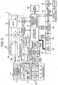
- the position detection sensors 12 and 13 and the drivers 21 to 24 in the motor driver block 20 operate in accordance with a control signal from a lens control block 58. These sensors and drivers send information such as sensor output, motor rotation rate, etc. to a control unit (CPU/ (Application Specific Integrated Circuit)) 50 via the lens control block 58.
- CPU/ Application Specific Integrated Circuit
- the CCD base 31 moves (shifts) in the vertical and horizontal directions perpendicular to the optical axis of the lenses within the CCD movable range, under the control of the control unit 50.
- An imagine signal after being output from the CCD 32, has its gain adjusted if needed, for the respective color components of RGB.
- the CDS/ADC block 33 denoises this analog output signal by correlated double sampling, converts it into a digital signal, and outputs it to a color process circuit 41.
- the CCD 32 is one type of imaging element, and other types of elements, such as CMOS may also be used.
- An audio block (audio CODEC) 35 comprises an audio input system and an audio output system.
- the audio input system comprises a microphone (MIC) 36 for receiving an audio and converting it into an analog audio signal, an A/D converter (ADC) 37 for converting an analog audio signal into a digital audio signal and sending it to the control unit 50 via a filter 38, etc.
- the audio output system comprises a D/A converter (DAC) 39 for converting a digital audio signal received from the control unit 50 via the filter 38 into an analog audio signal, a speaker (Speaker) 40 for converting an analog audio signal to restore an audio, amplifying it, and outputting it to the outside, etc.
- DAC D/A converter
- An audio signal sent to the control unit 50 via the microphone 36 and the A/D converter 37 is taken into a work memory 60.
- the signal taken into the work memory 60 is subjected to audio compression, and recorded together with a compressed moving image file, on an recording medium (such as an SD card) detachably attached on an image recording unit 80, as a moving image file (moving image data + audio data).
- the control unit 50 controls the lens control block 58 to generate a drive signal to be sent to the drivers 21 to 24 in the motor driver block 20 mentioned above, based on lens operation programs of various types and operation signals from a key circuit 95, etc.
- This signal controls the position of the zoom lens and focus lens, the opening degree of the iris, and the opening and closing operation of the mechanical shutter.
- information about the positions of the zoom lens and focus lens is sequentially input to the control unit 50 via the lens control block 58.
- the information about the positions of these lenses are detected by the position detection sensors 12 and 13 for detecting the zoom position and focus position.
- the pose sensor 65 detects a camera shake of the digital camera 1.
- an acceleration sensor may be used as the pose sensor 65.
- a pose detection result of the pose sensor 65 is output to the control unit 50 as a camera shake detection signal.
- the image display unit 70 comprises a video encoder, a VRAM controller, a VRAM, a liquid crystal display monitor, and a drive circuit for the monitor.
- the image display unit 70 generates a video signal based on a digital signal sent thereto, by the video encoder. Then, the image display unit 70 displays a display image based on the video signal, i.e., a through image of the photo object imaged by the CCD 32, menu data, etc. on the liquid crystal monitor screen 4.
- the image display unit 70 functions as a monitor display unit (electronic finder).
- the image display unit 70 performs a displaying operation based on a video signal from the video encoder, thereby displaying, in real time, an image based on image information acquired from the VRAM controller at that time.
- a trigger signal is generated when the shutter key 8 is operated while a through image is displayed.
- the control unit 50 continues the through image imaging process and the through image display process, while in accordance with this trigger signal, the control unit 50 controls the JPEG/MPEG unit 45 to MPEG-compress luminance and color difference signals for one frame acquired from the CCD 32 and sequentially stored in the work memory 60, and records the compressed data on the SD card in the image recording unit 80.
- the control unit 50 stops the compressing process and the recording process and returns to the state of displaying the through image.
- the cursor key 5 is a key to be operated for moving a cursor to point at (designating) a menu, an icon, etc. displayed on the liquid crystal monitor screen 4" upon mode setting, menu selection, etc.
- the cursor can be moved up or down, left or right, by operations on the cursor key 5.
- the SET key 6 is a confirmation key to be pressed when an item designated by the cursor is selected or confirmed.
- FIG. 5 is a flowchart showing one embodiment of the camera shake correction process at the time of through image display according to the present embodiment, and shows a detailed flowchart of step S2 of FIG. 4 .
- the following explanation will be given based on FIGS. 1 to 5 .
- the control unit 50 exposes the CCD 32 according to the shooting conditions such as the shutter speed, etc. obtained at step S8-1-1, while fixing the CCD base 31 (i.e., the CCD 32) at the center position (step S8-1-4). Further, the control unit 50 outputs an imaging signal of an image having a predetermined size (for example, 3200x2400 pixels) obtained with the use of the full area of the CCD 32, to the color process circuit 41 via the CDS/ADC block 33, and goes to step S8-1-6 (step S8-1-5).
- a predetermined size for example, 3200x2400 pixels
- the color process circuit 41 applies a color process for perforiming pixel interpolation to the imaging signal input thereto, and performs a YUV conversion process to generate a luminance signal (Y) and color difference signals (Cb, Cr) having digital values.
- the control unit 50 enlarges or reduces this processed data in accordance with the image size defined at step S8-1-3 or step S8-1-5, and goes to step S9 of FIG. 4 (step S8-1-6):
- the control unit 50 In a case where camera shake correction is determined to be necessary at step S2-2-3, the control unit 50 generates a drive signal to be sent to the CCD shift driver 55 in accordance with a shake detection value received from the pose sensor 65.
- CCD shift driver 55 moves, the position of the CCD base 31 (i.e., the CCD 32) in the X direction and the Y direction perpendicular to the optical axis of the lenses within the CCD movable range 102. Then, the flow goes to step S2-2-5 (step S2-2-4).
- control, unit 50 outputs an imaging signal of an image having a predetermined size (for example, 2560 ⁇ 1920 pixels) obtained with the use of the inner area of the use range of the CCD 32, to the color process circuit 41 via the CDS/ADC block 33, and goes to step S8-2-7 (step S8-2-4).
- a predetermined size for example, 2560 ⁇ 1920 pixels
- the above-described embodiment 2 it is automatically determined whether or not camera shake correction is necessary in accordance with the shooting conditions such as zooming magnification, shutter speed, etc., and which part of the CCD area is to be used.
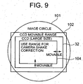
- the amount of camera shake increases as the camera zooms from the widest angle to a telescopic angle, it is possible to estimate the maximum value of the amount of camera shake based on the zoom position. Accordingly, it is possible to determine the use range (range of extraction) for camera shake correction at the center of the CCD area in accordance with the zoom position. That is, as shown in FIG. 9 , the size of the use range 104 within the CCD 32 at the time of camera shake correction can be changed in accordance with the zoom position (the use range 104 increases or decreases in accordance with the zoom position).
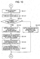
- the control unit 50 exposes the CCD 32 while the CCD 31 (i.e., the CCD 32) is fixed at the center position, sets the use range such that the entire area of the CCD 32 will be used, and goes to step S3 of FIG. 4 . Also in this case, since pixel merging or pixel decimation is performed at the time of through image display, the image size is set to a smaller size (for example, 640x480 pixels) than that at the time of still image shooting (step S2-3-8).
- the image signal output: at step S2-3-7 or at step S2-3-8 is displayed as a through image at step S2-3-2. In a case where the zooming magnification is changed at step S3, the zooming magnification after the change is obtained at step S2-3-1.
- the control unit 50 obtains the shooting conditions such as zoom position, shutter speed, etc. at that time (step S8-3-1). The control unit 50 determines whether or not camera shake correction is necessary based on the obtained shutter speed and zooming magnification. In a case where camera shake correction is necessary, the flow goes to step S8-3-3, and otherwise the flow goes to step S8-3-7. Whether camera shake correction is necessary or not can be determined in the same manner as that at step S2-2-3 of FIG. 7 (step S8-3-2).
- the maximum estimation value of the amount of camera shake at the obtained zoom position is calculated at step S8-3.-3 based on the zoom position information obtained at step S8-3-1, and the use range for camera shake correction at the center of the CCD area is determined at step S8-3-4 based on the maximum estimation value of the amount of camera shake.
- step S8-3-3 may be omitted so that the use range for camera shake correction at the center of the CCD area may be determined based directly on the zoom position information obtained at step S8-3-1.
- the digital camera 1 can use a CCD having a size corresponding to its lens size. It is possible to obtain an image which is not affected by over exposure, while using the pixels within as large an effective area as possible for camera shake correction. Further, it is possible to obtain an image having a high resolution, by using the entire area of the CCD 32 in a case where the camera shake correction process is not performed. Further, necessity and unnecessity for camera shake correction can be switched by automatic determination: Therefore, the user's workload can be reduced, and an image having a higher resolution can be obtained even when camera shake correction is performed.
- step S2-3-1 of FIG. 10 may be designed such that "the control unit 50 checks a signal from the key circuit 95, and turns on the camera shake correction function in a case where the key 10 is pressed”
- step S2-3-3 of FIG. 10 may be designed such that "in a case where the camera shake correction function is turned on, the flow goes to step S2-3-4, and otherwise, the flow goes to step S2-3-8”
- step S8-3-2 of FIG. 11 may be designed such that "in a case where the camera shake correction function is turned on, the flow goes to step S8-3-3, and otherwise, the flow goes to step S8-3-7".
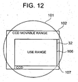
- FIG. 12 is an explanatory diagram of the use range within the CCD 32 for camera shake correction that is used in conjunction with the trajectory of camera shake correction, and shows one example of a use range 106 in a case where the CCD 32 is moved to the lower right within the CCD movable range 102. As shown in FIG. 12 , such a point 107 on the image circle 101 is obtained, that will make the use range 106 the largest when the CCD 32 goes beyond the image circle 101. Based on this, the use range 106 can be determined.
- FIG. 13 is a flowchart showing one embodiment of a camera shake correction process at the time of still image shooting according to the embodiment 4, and shows a detailed flowchart of step S8 of FIG. 4 .
- the following explanation will be given based on FIGS. 1 to 4 , FIG. 12 , and FIG. 13 .
- the control unit 50 obtains the shooting conditions such as zoom position, shutter speed at that time (step S8-4-1). The control unit 50 determines whether or not camera shake correction is necessary based on the obtained shutter speed and zooming magnification. In a case where camera shake correction is necessary, the flow goes to step S8-4-3, and otherwise, the flow goes to step S8-4-7. Whether camera shake correction is necessary or not can be determined in the same manner as that at step S2-2-3 of FIG. 7 (step S8-4-2).
- the control unit 50 exposes the CCD 32 in accordance with the shooting conditions such as shutter speed, etc. obtained at step S8-4-1, while the CCD base 31 (i.e., the CCD 32) is fixed at the center position (step S8-4-7). Further, the control unit 50 outputs an imaging signal of an image, having a predetermined size (for example, 3200x2400 pixels) that is obtained with the use of the entire area of the CCD 32 to the color process circuit 41 via the CDS/ADC block 33, and goes to step S8-4-9 (step S8-4-8).
- a predetermined size for example, 3200x2400 pixels
- the digital camera 1 can use a CCD having a size corresponding to its lens size. It is possible to obtain an image which is not affected by over exposure, while using the pixels within as large an effective area as possible for camera shake correction. Further, it is possible to obtain an image having a high resolution, by using the entire area of the CCD 32 in a case where the camera shake correction process is not performed. Furthermore, camera shake correction can be switched on/off by automatic determination. Accordingly, the user's workload can be reduced, and an image having the highest resolution possible can be obtained even when camera shake correction is performed.
- step S8-4-2 of FIG. 13 may be designed such that "in a case where the camera shake correction function is turned on, the flow goes to step S8-4-3, and otherwise, the flow goes to step S8-4-7".
- the present invention is applied to performing camera shake correction by moving the CCD 32.
- the present invention is not limited to this case.
- the present invention can also be applied to performing camera shake correction by moving the imaging lenses 2 as the optical system. That is, the present invention can be applied to performing camera shake correction by changing the relative positions of the imaging element and the optical system.
Landscapes
- Engineering & Computer Science (AREA)
- Multimedia (AREA)
- Signal Processing (AREA)
- Studio Devices (AREA)
- Exposure Control For Cameras (AREA)
- Adjustment Of Camera Lenses (AREA)
Abstract
Claims (14)
- Appareil d'imagerie comprenant :un élément d'imagerie (32) qui convertit opto-électriquement une image formée par un système optique (11) et sort un signal d'imagerie ;une unité de détection de secousse (65) qui détecte une secousse de l'appareil et sort un signal de détection de secousse, etune unité de correction de secousse (18, 55) qui effectue une correction de secousse en changeant les positions relatives de l'élément d'imagerie et du système optique sur la base du signal de détection de secousse provenant de l'unité de détection de secousse (64) ;caractérisé par
une unité de détermination de nécessité de correction de secousse (50) qui détermine si une correction de secousse doit être ou non effectuée par l'unité de correction de secousse (18, 55) ; et
une unité de commande (50) qui traite un signal d'imagerie lu depuis une première zone spécifique prédéfinie de l'élément d'imagerie (32) dans le cas où l'unité de détermination de nécessité de correction de secousse (50) détermine qu'une correction de secousse doit être effectuée, et traite un signal d'imagerie lu depuis une seconde zone spécifique de l'élément d'imagerie (32) qui est plus grande que la première zone spécifique et comprend la première zone spécifique dans le cas où l'unité de détermination de nécessité de correction de secousse (50) détermine qu'une correction de secousse ne doit pas être effectuée. - Appareil d'imagerie selon la revendication 1, comprenant :une unité de traitement de signal d'imagerie (30) qui traite un signal d'imagerie lu depuis l'élément d'imagerie (32),dans lequel l'unité de commande (50) comprend une unité qui commande l'unité de traitement de signal d'imagerie (50) pour traiter un signal d'imagerie lu depuis la première zone spécifique prédéfinie de l'élément d'imagerie (32) dans le cas où l'unité de détermination de nécessité de correction de secousse (50) détermine qu'une correction de secousse doit être effectuée, et commande l'unité de traitement de signal d'imagerie pour traiter un signal d'imagerie lu depuis la seconde zone spécifique de l'élément d'imagerie (32) plus grande que la première zone spécifique et comprenant la première zone spécifique dans le cas où l'unité de détermination de nécessité de correction de secousse (50) détermine qu'une correction de secousse ne doit pas être effectuée.
- Appareil d'imagerie selon la revendication 2, dans lequel l'unité de traitement de signal d'imagerie (50) comprend une unité de traitement d'affichage de signal d'imagerie (50) qui effectue un traitement pour afficher un signal d'imagerie lu depuis l'élément d'imagerie (32), ou une unité de traitement d'enregistrement de signal d'imagerie (50) qui effectue un traitement pour enregistrer un signal d'imagerie lu depuis l'élément d'imagerie (32).
- Appareil d'imagerie selon l'une quelconque des revendications 1 à 3, comprenant :une unité de commutation de plage de lecture (50) qui commute des plages de lecture à partir desquelles un signal d'imagerie est lu depuis l'élément d'imagerie (32),dans lequel l'unité de commande (50) comprend une unité qui commande l'unité de commutation de plage de lecture (50) de sorte qu'un signal d'imagerie soit lu depuis la première zone spécifique prédéfinie de l'élément d'imagerie (32) dans le cas où l'unité de détermination de nécessité de correction de secousse (50) détermine qu'une correction de secousse doit être effectuée, et commande l'unité de commutation de plage de lecture (50) de sorte qu'un signal d'imagerie soit lu depuis la seconde zone spécifique de l'élément d'imagerie (32) plus grande que la première zone spécifique et comprenant la première zone spécifique dans le cas où l'unité de détermination de nécessité de correction de secousse (50) détermine qu'une correction de secousse ne doit pas être effectuée.
- Appareil d'imagerie selon l'une quelconque des revendications 1 à 4, dans lequel la position centrale de la première zone spécifique coïncide avec celle d'une zone globale de l'élément d'imagerie (32), et la seconde zone spécifique est la zone globale de l'élément d'imagerie (32).
- Appareil d'imagerie selon l'une quelconque des revendications 1 à 5, comprenant :une unité d'obtention de condition de prise de vue (50) qui obtient une condition de prise de vue prédéterminée,dans lequel l'unité de détermination de nécessité de correction de secousse (50) détermine s'il est ou non nécessaire d'effectuer une correction de secousse sur la base de la condition de prise de vue obtenue par l'unité d'obtention de condition de prise de vue (50).
- Appareil d'imagerie selon l'une quelconque des revendications 1 à 5, comprenant :une unité d'obtention de condition de prise de vue (50) qui obtient une condition de prise de vue prédéterminée,dans lequel l'unité de commande (50) comprend une unité qui change la première zone spécifique de l'élément d'imagerie (32) sur la base de la condition de prise de vue obtenue par l'unité d'obtention de condition de prise de vue (50), dans le cas où l'unité de détermination de nécessité de correction de secousse (50) détermine qu'une correction de secousse doit être effectuée.
- Appareil d'imagerie selon la revendication 6 ou 7, dans lequel la condition de prise de vue prédéterminée comprend un agrandissement du zoom ou une vitesse d'obturation.
- Appareil d'imagerie selon l'une quelconque des revendications 1 à 8, dans lequel l'unité de correction de secousse (18, 55) effectue une correction de secousse en déplaçant l'élément d'imagerie (32) sur la base d'un signal de détection de secousse provenant de l'unité de détection de secousse (65).
- Appareil d'imagerie selon la revendication 9, comprenant :une unité d'obtention de position de déplacement (50) qui obtient une position de l'élément d'imagerie (32) déplacée par une correction de secousse (18, 55) sur la base du signal de détection de secousse provenant de l'unité de détection de secousse (65),dans lequel l'unité de commande (50) comprend une unité qui change la première zone spécifique de l'élément d'imagerie (32) sur la base de la position de l'élément d'imagerie (32) obtenue par l'unité d'obtention de position de déplacement (50), dans le cas où l'unité de détermination de nécessité de correction de secousse (50) détermine qu'une correction de secousse doit être effectuée.
- Appareil d'imagerie selon l'une quelconque des revendications 1 à 8, dans lequel l'unité de correction de secousse (18, 55) effectue une correction de secousse en déplaçant le système optique (11) sur la base du signal de détection de secousse provenant de l'unité de détection de secousse (65).
- Appareil d'imagerie selon la revendication 11, comprenant :une unité d'obtention de position de déplacement (50) qui obtient une position du système optique (11) déplacée par une correction de secousse sur la base du signal de détection de secousse provenant de l'unité de détection de secousse (65),dans lequel l'unité de commande (50) comprend une unité qui change la première zone spécifique de l'élément d'imagerie (32) sur la base de la position du système optique (11) obtenue par l'unité d'obtention de position de déplacement (50), dans le cas où l'unité de détermination de nécessité de correction de secousse (50) détermine qu'une correction de secousse doit être effectuée.
- Procédé d'extraction de données impliquant l'utilisation d'un appareil d'imagerie comprenant : un élément d'imagerie (32) qui convertit opto-électriquement une image formée par un système optique (11) et sort un signal d'imagerie ; une unité de détection de secousse (65) qui détecte une secousse de l'appareil et sort un signal de détection de secousse ; et une unité de correction de secousse (18, 55) qui effectue une correction de secousse en changeant les positions relatives de l'élément d'imagerie (32) et du système optique (11) sur la base du signal de détection de secousse provenant de l'unité de détection de secousse (65), le procédé comprenant : une étape de détermination de nécessité de correction de secousse consistant à déterminer si une correction de secousse doit être ou non effectuée par l'unité de correction de secousse (18, 55) ; et une étape de commande consistant à traiter un signal d'imagerie lu depuis une première zone spécifique prédéfinie de l'élément d'imagerie (32) dans le cas où il est déterminé lors de l'étape de détermination de nécessité de correction de secousse qu'une correction de secousse doit être effectuée, et à traiter un signal d'imagerie lu depuis une seconde zone spécifique de l'élément d'imagerie (32) qui est plus grande que la première zone spécifique et comprend la première zone spécifique dans le cas où il est déterminé qu'une correction de secousse ne doit pas être effectuée.
- Programme d'extraction de données pour un ordinateur d'un appareil d'imagerie comprenant : un élément d'imagerie (32) qui convertit opto-électriquement une image formée par un système optique (11) et sort un signal d'imagerie ; une unité de détection de secousse (65) qui détecte une secousse de l'appareil et sort un signal de détection de secousse ; et une unité de correction de secousse (18, 55) qui effectue une correction de secousse en changeant les positions relatives de l'élément d'imagerie (32) et du système optique (11) sur la base du signal de détection de secousse provenant de l'unité de détection de secousse (65), le programme commandant l'ordinateur pour effectuer : une fonction consistant à déterminer si une correction de secousse doit être ou non effectuée par l'unité de correction de secousse (18, 55) ; et une fonction de commande consistant à traiter un signal d'imagerie lu depuis une première zone spécifique prédéfinie de l'élément d'imagerie (32) dans le cas où il est déterminé par la fonction de détermination qu'une correction de secousse doit être effectuée, et à traiter un signal d'imagerie lu depuis une seconde zone spécifique de l'élément d'imagerie (32) qui est plus grande que la première zone spécifique et comprend la première zone spécifique dans le cas où il est déterminé qu'une correction de secousse ne doit pas être effectuée.
Applications Claiming Priority (2)
| Application Number | Priority Date | Filing Date | Title |
|---|---|---|---|
| JP2005266266A JP4305434B2 (ja) | 2005-09-14 | 2005-09-14 | 電子カメラ及びプログラム |
| PCT/JP2006/318676 WO2007032558A1 (fr) | 2005-09-14 | 2006-09-14 | Appareil d'imagerie, procede d'extraction de donnees et programme d'extraction de donnees |
Publications (2)
| Publication Number | Publication Date |
|---|---|
| EP1925153A1 EP1925153A1 (fr) | 2008-05-28 |
| EP1925153B1 true EP1925153B1 (fr) | 2009-05-13 |
Family
ID=37402644
Family Applications (1)
| Application Number | Title | Priority Date | Filing Date |
|---|---|---|---|
| EP06810356A Not-in-force EP1925153B1 (fr) | 2005-09-14 | 2006-09-14 | Appareil d'imagerie, procede d'extraction de donnees et programme d'extraction de donnees |
Country Status (8)
| Country | Link |
|---|---|
| US (1) | US7689108B2 (fr) |
| EP (1) | EP1925153B1 (fr) |
| JP (1) | JP4305434B2 (fr) |
| KR (1) | KR100906522B1 (fr) |
| CN (2) | CN101263707A (fr) |
| DE (1) | DE602006006848D1 (fr) |
| TW (1) | TWI326553B (fr) |
| WO (1) | WO2007032558A1 (fr) |
Families Citing this family (22)
| Publication number | Priority date | Publication date | Assignee | Title |
|---|---|---|---|---|
| JP5013078B2 (ja) * | 2007-04-24 | 2012-08-29 | コニカミノルタアドバンストレイヤー株式会社 | レンズ鏡胴及び撮像装置 |
| KR20090015251A (ko) * | 2007-08-08 | 2009-02-12 | 삼성전자주식회사 | 이미지 센서를 구비한 카메라 모듈 |
| KR101431541B1 (ko) * | 2008-01-18 | 2014-08-19 | 삼성전자주식회사 | 디지털 카메라에서 유효한 영상을 분류하는 방법 |
| JP4957617B2 (ja) * | 2008-03-28 | 2012-06-20 | カシオ計算機株式会社 | 撮像装置及びそのプログラム |
| JP5293947B2 (ja) * | 2008-11-13 | 2013-09-18 | 株式会社ニコン | 撮像装置 |
| JP5419647B2 (ja) * | 2009-11-16 | 2014-02-19 | キヤノン株式会社 | 像振れ補正装置およびそれを備えた撮像装置、像振れ補正装置の制御方法 |
| JP5493942B2 (ja) * | 2009-12-15 | 2014-05-14 | ソニー株式会社 | 撮像装置と撮像方法 |
| US8643734B2 (en) | 2010-11-10 | 2014-02-04 | Apple Inc. | Automatic engagement of image stabilization |
| US20120113515A1 (en) * | 2010-11-10 | 2012-05-10 | Karn Keith S | Imaging system with automatically engaging image stabilization |
| KR101862432B1 (ko) | 2010-12-17 | 2018-05-29 | 유니버시티 오브 플로리다 리서치 파운데이션, 인코포레이티드 | 탄소 필름상에서의 수소 산화 및 발생 |
| CN102572252A (zh) * | 2010-12-28 | 2012-07-11 | 华晶科技股份有限公司 | 电子装置、影像拍摄装置及其控制方法 |
| US9053993B2 (en) | 2011-10-07 | 2015-06-09 | Semiconductor Components Industries, Llc | Imaging systems with selectable column power control |
| JP5536010B2 (ja) * | 2011-11-02 | 2014-07-02 | カシオ計算機株式会社 | 電子カメラ、撮像制御プログラム及び撮像制御方法 |
| US20140253785A1 (en) * | 2013-03-07 | 2014-09-11 | Mediatek Inc. | Auto Focus Based on Analysis of State or State Change of Image Content |
| KR102238775B1 (ko) * | 2014-02-10 | 2021-04-09 | 삼성전자주식회사 | 전자 장치에서 증강 현실을 이용한 장비 관리 장치 및 방법 |
| KR102041647B1 (ko) | 2014-06-30 | 2019-11-07 | 삼성전기주식회사 | 카메라의 보정 시스템 및 그 보정방법 |
| CN106156676B (zh) * | 2015-04-15 | 2019-04-19 | 广州诚迈伟讯物联网技术有限公司 | 一种影像式ccd条码快速识别方法及装置 |
| US9912868B2 (en) * | 2015-09-15 | 2018-03-06 | Canon Kabushiki Kaisha | Image-blur correction apparatus, tilt correction apparatus, method of controlling image-blur correction apparatus, and method of controlling tilt correction apparatus |
| JP6470478B2 (ja) * | 2016-09-14 | 2019-02-13 | 富士フイルム株式会社 | 撮像装置及び撮像制御方法 |
| JP2019117977A (ja) * | 2017-12-26 | 2019-07-18 | キヤノン株式会社 | 防振制御装置、撮像装置、撮像システム、制御方法及びプログラム |
| JP6967673B2 (ja) * | 2018-01-09 | 2021-11-17 | イマーヴィジョン インコーポレイテッドImmervision Inc. | 解像度が一定な連続的ハイブリッドズームシステム |
| JP2020096301A (ja) * | 2018-12-13 | 2020-06-18 | オリンパス株式会社 | 撮像装置 |
Family Cites Families (19)
| Publication number | Priority date | Publication date | Assignee | Title |
|---|---|---|---|---|
| JPH0474070A (ja) | 1990-07-14 | 1992-03-09 | Sony Corp | 手振れ補正装置 |
| US5990942A (en) * | 1991-05-01 | 1999-11-23 | Canon Kabushiki Kaisha | Photographing apparatus using image information for blurring correction |
| US6172707B1 (en) * | 1992-06-22 | 2001-01-09 | Canon Kabushiki Kaisha | Image pickup device |
| JPH07203279A (ja) | 1993-12-28 | 1995-08-04 | Hitachi Ltd | 撮像装置 |
| JPH0829825A (ja) * | 1994-07-18 | 1996-02-02 | Nikon Corp | 防振装置 |
| JP2000224470A (ja) * | 1999-02-02 | 2000-08-11 | Minolta Co Ltd | カメラシステム |
| JP3939889B2 (ja) * | 2000-02-01 | 2007-07-04 | ペンタックス株式会社 | 像振れ防止デジタルカメラ |
| US6803953B2 (en) * | 2000-02-28 | 2004-10-12 | Canon Kabushiki Kaisha | Image sensing apparatus and method having noise reduction function |
| JP2002218312A (ja) * | 2001-01-17 | 2002-08-02 | Ricoh Co Ltd | ソフトフォーカス撮影可能なカメラ |
| JP2004258250A (ja) | 2003-02-25 | 2004-09-16 | Kyocera Corp | ブレ補正装置及びそれを用いた撮像装置 |
| JP2004264418A (ja) * | 2003-02-28 | 2004-09-24 | Casio Comput Co Ltd | カメラ装置、及びカメラ装置の起動方法、プログラム |
| JP3867680B2 (ja) * | 2003-04-01 | 2007-01-10 | ソニー株式会社 | 撮像装置および手振れ補正方法 |
| JP3917104B2 (ja) * | 2003-04-25 | 2007-05-23 | コニカミノルタフォトイメージング株式会社 | 撮像装置 |
| JP4391783B2 (ja) | 2003-09-11 | 2009-12-24 | Hoya株式会社 | 光学機器 |
| JP4478422B2 (ja) * | 2003-09-18 | 2010-06-09 | キヤノン株式会社 | 像振れ補正装置、交換レンズおよび撮影装置 |
| JP4717382B2 (ja) * | 2004-06-15 | 2011-07-06 | キヤノン株式会社 | 光学機器 |
| TWI375112B (en) * | 2004-06-24 | 2012-10-21 | Pentax Ricoh Imaging Co Ltd | Digital camera |
| JP4796755B2 (ja) * | 2004-07-01 | 2011-10-19 | Hoya株式会社 | 像ブレ補正装置 |
| JP4022595B2 (ja) * | 2004-10-26 | 2007-12-19 | コニカミノルタオプト株式会社 | 撮影装置 |
-
2005
- 2005-09-14 JP JP2005266266A patent/JP4305434B2/ja not_active Expired - Fee Related
-
2006
- 2006-09-13 US US11/520,552 patent/US7689108B2/en not_active Expired - Fee Related
- 2006-09-13 TW TW095133875A patent/TWI326553B/zh not_active IP Right Cessation
- 2006-09-14 DE DE602006006848T patent/DE602006006848D1/de active Active
- 2006-09-14 KR KR1020077022764A patent/KR100906522B1/ko not_active Expired - Fee Related
- 2006-09-14 CN CNA2006800336209A patent/CN101263707A/zh active Pending
- 2006-09-14 WO PCT/JP2006/318676 patent/WO2007032558A1/fr not_active Ceased
- 2006-09-14 EP EP06810356A patent/EP1925153B1/fr not_active Not-in-force
- 2006-09-14 CN CN2011102598139A patent/CN102307279A/zh active Pending
Also Published As
| Publication number | Publication date |
|---|---|
| KR100906522B1 (ko) | 2009-07-07 |
| JP2007081770A (ja) | 2007-03-29 |
| DE602006006848D1 (de) | 2009-06-25 |
| CN101263707A (zh) | 2008-09-10 |
| KR20070117644A (ko) | 2007-12-12 |
| US20070058957A1 (en) | 2007-03-15 |
| EP1925153A1 (fr) | 2008-05-28 |
| TWI326553B (en) | 2010-06-21 |
| JP4305434B2 (ja) | 2009-07-29 |
| US7689108B2 (en) | 2010-03-30 |
| WO2007032558A1 (fr) | 2007-03-22 |
| TW200715836A (en) | 2007-04-16 |
| CN102307279A (zh) | 2012-01-04 |
| WO2007032558A9 (fr) | 2007-08-02 |
Similar Documents
| Publication | Publication Date | Title |
|---|---|---|
| US7689108B2 (en) | Imaging apparatus, data extraction method, and data extraction program | |
| EP2131572B1 (fr) | Caméra, programme de commande de caméra et procédé de commande de caméra | |
| JP4929630B2 (ja) | 撮像装置、制御方法、およびプログラム | |
| US20100079623A1 (en) | Image capturing apparatus, image capturing method and storage medium | |
| JPH10240436A (ja) | 情報処理装置および記録媒体 | |
| JP2008009263A (ja) | 撮像装置及びそのプログラム | |
| US20060077263A1 (en) | Method of capturing still image during capture of moving image and image capture apparatus | |
| WO2008010559A1 (fr) | Appareil d'imagerie | |
| KR101433121B1 (ko) | 소정의 종횡비의 합성 화상을 생성하는 화상 처리 장치 | |
| JP2009225027A (ja) | 撮像装置、撮像制御方法、及びプログラム | |
| JP5061418B2 (ja) | デジタルカメラ、及びその動作方法 | |
| KR20090045117A (ko) | 휴대용 장치 및 촬상 장치 | |
| JP5742237B2 (ja) | 撮像装置および撮像方法 | |
| JP4788172B2 (ja) | 撮像装置及びプログラム | |
| JP4609315B2 (ja) | 撮像装置、ズーム時の画角枠表示方法、およびプログラム | |
| JP2007166011A (ja) | 撮像装置及びそのプログラム | |
| JP2007104038A (ja) | 撮像装置、高速起動撮影方法、及びプログラム | |
| JP5105298B2 (ja) | 撮像装置及びそのプログラム | |
| JP4807218B2 (ja) | 撮像装置及びプログラム | |
| HK1122934A (en) | Imaging apparatus, data extraction method, and data extraction program | |
| JP2007171669A (ja) | 撮像装置 | |
| JP2007221375A (ja) | カメラシステム制御装置、そのプログラムおよびコンピュータ読取可能な記録媒体、カメラシステム、ならびにカメラシステムの制御方法 | |
| JP2007166447A (ja) | 撮像装置、ズーム表示方法、およびプログラム | |
| JP2010081099A (ja) | 撮像装置及びそのプログラム | |
| JP2011166496A (ja) | 撮像装置 |
Legal Events
| Date | Code | Title | Description |
|---|---|---|---|
| PUAI | Public reference made under article 153(3) epc to a published international application that has entered the european phase |
Free format text: ORIGINAL CODE: 0009012 |
|
| 17P | Request for examination filed |
Effective date: 20070913 |
|
| AK | Designated contracting states |
Kind code of ref document: A1 Designated state(s): DE FR GB |
|
| 17Q | First examination report despatched |
Effective date: 20080811 |
|
| RBV | Designated contracting states (corrected) |
Designated state(s): DE FR GB |
|
| GRAP | Despatch of communication of intention to grant a patent |
Free format text: ORIGINAL CODE: EPIDOSNIGR1 |
|
| DAX | Request for extension of the european patent (deleted) | ||
| GRAS | Grant fee paid |
Free format text: ORIGINAL CODE: EPIDOSNIGR3 |
|
| GRAA | (expected) grant |
Free format text: ORIGINAL CODE: 0009210 |
|
| AK | Designated contracting states |
Kind code of ref document: B1 Designated state(s): DE FR GB |
|
| REG | Reference to a national code |
Ref country code: GB Ref legal event code: FG4D |
|
| REF | Corresponds to: |
Ref document number: 602006006848 Country of ref document: DE Date of ref document: 20090625 Kind code of ref document: P |
|
| PLBE | No opposition filed within time limit |
Free format text: ORIGINAL CODE: 0009261 |
|
| STAA | Information on the status of an ep patent application or granted ep patent |
Free format text: STATUS: NO OPPOSITION FILED WITHIN TIME LIMIT |
|
| 26N | No opposition filed |
Effective date: 20100216 |
|
| REG | Reference to a national code |
Ref country code: FR Ref legal event code: PLFP Year of fee payment: 10 |
|
| PGFP | Annual fee paid to national office [announced via postgrant information from national office to epo] |
Ref country code: FR Payment date: 20150626 Year of fee payment: 10 |
|
| PGFP | Annual fee paid to national office [announced via postgrant information from national office to epo] |
Ref country code: GB Payment date: 20150917 Year of fee payment: 10 Ref country code: DE Payment date: 20150922 Year of fee payment: 10 |
|
| REG | Reference to a national code |
Ref country code: DE Ref legal event code: R119 Ref document number: 602006006848 Country of ref document: DE |
|
| GBPC | Gb: european patent ceased through non-payment of renewal fee |
Effective date: 20160914 |
|
| REG | Reference to a national code |
Ref country code: FR Ref legal event code: ST Effective date: 20170531 |
|
| PG25 | Lapsed in a contracting state [announced via postgrant information from national office to epo] |
Ref country code: DE Free format text: LAPSE BECAUSE OF NON-PAYMENT OF DUE FEES Effective date: 20170401 Ref country code: FR Free format text: LAPSE BECAUSE OF NON-PAYMENT OF DUE FEES Effective date: 20160930 Ref country code: GB Free format text: LAPSE BECAUSE OF NON-PAYMENT OF DUE FEES Effective date: 20160914 |