EP1923748A2 - Bilderzeugungsvorrichtung mit einer Fixier- und Steuervorrichtung - Google Patents
Bilderzeugungsvorrichtung mit einer Fixier- und Steuervorrichtung Download PDFInfo
- Publication number
- EP1923748A2 EP1923748A2 EP07119234A EP07119234A EP1923748A2 EP 1923748 A2 EP1923748 A2 EP 1923748A2 EP 07119234 A EP07119234 A EP 07119234A EP 07119234 A EP07119234 A EP 07119234A EP 1923748 A2 EP1923748 A2 EP 1923748A2
- Authority
- EP
- European Patent Office
- Prior art keywords
- fusing
- temperature
- fusing roller
- roller
- trigger signals
- Prior art date
- Legal status (The legal status is an assumption and is not a legal conclusion. Google has not performed a legal analysis and makes no representation as to the accuracy of the status listed.)
- Withdrawn
Links
- 238000001514 detection method Methods 0.000 claims abstract description 11
- 238000000034 method Methods 0.000 claims description 54
- 230000008569 process Effects 0.000 claims description 45
- 238000001816 cooling Methods 0.000 claims description 19
- 238000010438 heat treatment Methods 0.000 claims description 15
- 230000002093 peripheral effect Effects 0.000 description 26
- 238000007639 printing Methods 0.000 description 20
- 230000006870 function Effects 0.000 description 9
- 230000000452 restraining effect Effects 0.000 description 5
- 230000007246 mechanism Effects 0.000 description 4
- 238000013021 overheating Methods 0.000 description 4
- 230000009467 reduction Effects 0.000 description 4
- 238000010586 diagram Methods 0.000 description 3
- 238000004891 communication Methods 0.000 description 2
- 238000011161 development Methods 0.000 description 2
- 230000004048 modification Effects 0.000 description 2
- 238000012986 modification Methods 0.000 description 2
- 238000012545 processing Methods 0.000 description 2
- 230000005540 biological transmission Effects 0.000 description 1
- 238000005516 engineering process Methods 0.000 description 1
- 230000006872 improvement Effects 0.000 description 1
- 239000004973 liquid crystal related substance Substances 0.000 description 1
- 238000012423 maintenance Methods 0.000 description 1
- 239000002184 metal Substances 0.000 description 1
- 238000002360 preparation method Methods 0.000 description 1
- 230000004044 response Effects 0.000 description 1
Images
Classifications
-
- G—PHYSICS
- G03—PHOTOGRAPHY; CINEMATOGRAPHY; ANALOGOUS TECHNIQUES USING WAVES OTHER THAN OPTICAL WAVES; ELECTROGRAPHY; HOLOGRAPHY
- G03G—ELECTROGRAPHY; ELECTROPHOTOGRAPHY; MAGNETOGRAPHY
- G03G15/00—Apparatus for electrographic processes using a charge pattern
- G03G15/50—Machine control of apparatus for electrographic processes using a charge pattern, e.g. regulating differents parts of the machine, multimode copiers, microprocessor control
- G03G15/5004—Power supply control, e.g. power-saving mode, automatic power turn-off
-
- G—PHYSICS
- G03—PHOTOGRAPHY; CINEMATOGRAPHY; ANALOGOUS TECHNIQUES USING WAVES OTHER THAN OPTICAL WAVES; ELECTROGRAPHY; HOLOGRAPHY
- G03G—ELECTROGRAPHY; ELECTROPHOTOGRAPHY; MAGNETOGRAPHY
- G03G15/00—Apparatus for electrographic processes using a charge pattern
- G03G15/20—Apparatus for electrographic processes using a charge pattern for fixing, e.g. by using heat
- G03G15/2003—Apparatus for electrographic processes using a charge pattern for fixing, e.g. by using heat using heat
- G03G15/2014—Apparatus for electrographic processes using a charge pattern for fixing, e.g. by using heat using heat using contact heat
- G03G15/2039—Apparatus for electrographic processes using a charge pattern for fixing, e.g. by using heat using heat using contact heat with means for controlling the fixing temperature
Definitions
- the present invention relates to an image forming apparatus including a fusing roller that heats a developed image transferred to a recording medium and fuses the same on the recording medium.
- the fusing roller In order to restrain the temperature fluctuations and the temperature difference from the periphery of the fusing roller, it is preferable to heat the fusing roller while being rotated. However, the rotation of the fusing roller more than necessary may increase the noise and the power consumption.
- a fusing roller for heating and fusing a developed image transferred to a recording medium; a heater for heating the fusing roller; a temperature detection sensor for detecting the temperature of the fusing roller or of the periphery thereof; a drive mechanism for rotating the fusing roller; and a control unit for controlling the heater and the drive mechanism on the basis of the detected temperature from the temperature detection sensor, and the control unit controls the heater to maintain the detected temperature at a reference fusing temperature until a predetermined time period is elapsed from an entry of trigger signals for starting preheating provided prior to an entry of a print command and stops the heater when the predetermined time period has elapsed, and operates the drive mechanism until the detected temperature reaches the reference fusing temperature in a case in which the temperature detected when the trigger signals are entered is lower than the reference fusing temperature, and stops the drive mechanism when the detected temperature reaches the reference fusing temperature.
- the control unit when the trigger signals are entered by a plurality of times during a time period from one fusing process to a next fusing process carried out by the fusing roller, the control unit does not carry out control to preheat the fusing roller for entries of the trigger signals from the second time onward.
- a cooling fan controlled by the control unit for cooling the fusing roller and the periphery thereof is provided.
- the control unit causes preheating to be carried out without operating the cooling fan when the trigger signals are entered for the first time and causes preheating to be carried out with the cooling fan operated when the trigger signals are entered from the second time onward during a period from one fusing process to a next fusing process carried out by the fusing roller.
- the image forming apparatus includes a copying function, and the trigger signal is provided in association with opening of a platen cover of a flat bed scanner, set-up of a document on an auto document feeder unit, or selection of Copy mode.
- the time required from reception of the print command until the start of the actual printing process may be shortened.
- the fusing roller If the detected temperature of the fusing roller or the periphery thereof is lower than the reference fusing temperature when the trigger signals for starting preheating are entered, the fusing roller is heated while being rotated until the detected temperature reaches the reference fusing temperature.
- the fusing roller By rotating the fusing roller during the preheating of the fusing roller, the fusing roller can be preheated while restraining temperature fluctuations of the fusing roller or the temperature difference from peripheral components (for example, a nip roller).
- the fusing roller When the detected temperature reaches the reference fusing temperature even once after having entered the trigger signals, the fusing roller is preheated in a state in which the rotation of the fusing roller is stopped. When the predetermined time period is elapsed from the entry of the trigger signals, the heating process is stopped. Therefore, the fusing roller can be preheated while restraining noise and power consumption.
- the preheating operation is not carried out for the entries of the trigger signals from the second time onward. Therefore, overheating of the interior of the image forming apparatus or increase in power consumption due to the repeated preheating operation may be avoided.
- the preheating is carried out without operating the cooling fan.
- the fusing roller is preheated with the cooling fan operated. Therefore, the fusing roller can be preheated while considering noise and power consumption caused by the operation of the cooling fan, and overheating of the interior of the image forming apparatus caused by preheating.
- preheating of the fusing roller is started in association with opening of the platen cover of the flat bed scanner, set-up of the document on the auto document feeder unit, or selection of Copy mode.
- the copying process (printing process) can be carried out immediately when a start button for carrying out the copying process is actually operated.
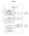
- Fig. 1 is a block diagram illustrating a configuration of a facsimile multifunction peripheral according to an embodiment of the invention.
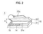
- Fig. 2 is a perspective sketch illustrating an appearance of an upper portion of the facsimile multifunction peripheral.
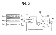
- Fig. 3 is a block diagram illustrating a principal portion of the configuration in Fig. 1 in detail.
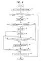
- Fig. 4 is a flowchart of a process of preheating a fusing roller.
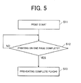
- Fig. 5 is a flowchart of a process when a preheating complete flag is initialized.
- Fig. 1 is a block diagram showing the configuration of a facsimile multifunction peripheral according to an embodiment of the invention.
- Fig. 2 is a perspective sketch showing the appearance of an upper portion of the facsimile multifunction peripheral in Fig. 1.
- a facsimile multifunction peripheral 1 includes a control unit 11, a scanner 12, a printer 13, a display unit 14, an operation unit 15, a memory unit 16, a modulator and demodulator (MODEM) 18, a network control unit (NCU) 17 and a network communication unit 19 as shown in Fig 1 and Fig. 2.
- Functions of the facsimile multifunction peripheral 1 include facsimile function, copying function scanning function and printer function.
- the control unit 11 serves to supervise control of the facsimile multifunction peripheral 1, and includes a central processing unit (CPU).
- CPU central processing unit
- the scanner 12 serves to scan a document, and is used for reading the document when transmitting facsimile, and reading the document when using the scanner function.
- the scanner 12 includes a scanning unit 21 as a flat bed scanner that scans the document, and an auto document feeder (ADF) unit 22 that feeds the document to the scanning unit 21.
- ADF unit 22 can be opened and closed as shown by an arrow A in Fig. 2, and also serves as a cover for covering a platen surface 21a of the scanning unit 21.
- the scanner 12 is provided with a detection switch 12a (see Fig. 3) for detecting the fact that the ADF unit 22 is opened and a detection switch 12b (see Fig. 3) for detecting the fact that the document is placed on a platen 22a of the ADF unit 22.
- the printer 13 includes a developing unit 31 and a fusing unit 32, and prints document data on a recording paper P (see Fig. 3) as a recording medium.
- the developing unit 31 includes a development roller, not illustrated, so that a toner image (developed image) formed on the basis of the document data using the development roller is transferred to the recording paper P.
- the fusing unit 32 includes a fusing roller 41 for heating and fusing the toner image transferred to the recording paper P, a heater 42 for heating the fusing roller 41, a temperature sensor (for example, a thermistor) 43 for detecting the temperature ⁇ of the fusing roller 41, a nip roller 44 for nipping the recording paper P in cooperation with the fusing roller 41 in a pressurized state, a motor 45 for rotating the fusing roller 41 and a cooling fan 46 for cooling the fusing unit 32 and the peripheral components as shown in Fig. 3.
- the temperature of the fusing roller 41 is detected by the temperature sensor 43.
- the fusing roller 41 is rotated by the motor 45.
- the temperature control of the fusing roller 41 by the heater 42 is carried out by the control unit 11 on the basis of the detection result from the temperature sensor 43.
- the control unit 11 also controls the motor 45 and the cooling fan 46.
- the fusing roller 41 is heated to a predetermined fusing temperature ⁇ f (for example, 175°C) by the heater 42 when carrying out fusing. Then, when printing, the fusing roller 41 and the nip roller 44 are rotated by the motor 45 in a state in which the fusing roller 41 is heated to the fusing temperature ⁇ f, and the recording paper P having a toner image transferred thereto is fed into the nip of the rollers 41 and 44. When the recording paper P is fed, the toner image transferred to the recording paper P is heated by the fusing roller 41, and is fused on the recording paper P. When fusing, the cooling fan 46 rotates to cool the fusing unit 32. When the heater 42 after having finished the printing process is turned off, the temperatures of the fusing roller 41 and the periphery thereof are lowered to the room temperature with time.
- a predetermined fusing temperature ⁇ f for example, 175°C
- the fusing roller 41 is preheated on the basis of trigger signals for starting preheating provided prior to a print command. This point will be described in detail later.
- the display unit 14 is composed of a liquid crystal display, and is used for displaying information for operating the facsimile multifunction peripheral 1.
- the operation unit 15 includes a plurality of operating buttons or a touch screen, and is used for operating the facsimile multifunction peripheral 1.
- the operation unit 15 is provided with a mode selection button (for example, copy mode button 15a (see Fig. 3)) for switching an operation mode of the facsimile multifunction peripheral 1 among copy, facsimile and scanner.
- the memory unit 16 includes a storage device such as a solid-state memory. Document data which is read using the scanner function and data relating the set-up parameters or maintenance management of the facsimile multifunction peripheral 1 are stored in the memory unit 16.
- the MODEM 18 includes a facsimile modem which can carry out facsimile transmission.
- the MODEM 18 is directly connected to the NCU 17.
- the NCU 17 is hardware for connecting and releasing a line with respect to an analogue public switched telephone network (PSTN) 51, and connects the MODEM 18 with the PSTN 51 as needed. It is also possible to provide an Integrated Services Digital Network (ISDN) interface and connect to the ISDN.
- PSTN public switched telephone network
- ISDN Integrated Services Digital Network
- the network communication unit 19 functions as an interface for connecting the facsimile multifunction peripheral 1 to a network 52 including LAN and Internet, and sends and receives data via the LAN or the Internet.
- the control unit 11 is adapted to carry out control to start heating of the fusing roller 41 in association with an entry of the print command as well as control to preheat the fusing roller 41 in response to the trigger signals for starting preheating provided prior to actual provision of the print command.
- control to start heating of the fusing roller 41 in association with an entry of the print command as well as control to preheat the fusing roller 41 in response to the trigger signals for starting preheating provided prior to actual provision of the print command.
- the print command here is to be emitted, for example, when the copy mode button in the operation unit 15 is pressed, when printing a received facsimile message, and when the print job is received via the network 52.
- the trigger signals for starting preheating employed here are, for example, signals which are emitted before starting a copying process and are effective as a trigger for starting a preparation of the printing process. More specifically, in this embodiment, a signal ts1 for opening the ADF unit 22 (cover) by the detection switch 12a in a state in which the operation mode of the facsimile multifunction peripheral 1 is Copy mode, a signal ts2 that detects the document on the platen 22a by the detection switch 12b in the state in which the operation mode of the facsimile multifunction peripheral 1 is also Copy mode, and a signal ts3 in association with the operation of the copy mode button 15a are used as the trigger signals for starting preheating.
- Step S1 opening of the ADF unit 22 (cover), setting of a document on the platen 22a, or operation of the copy mode button 15a are carried out in Copy mode, and when the trigger signals for starting preheating are entered, the procedure goes to Step S2.
- Step S2 the control unit 11 determines whether or not a preheating complete flag is set (whether or not a flag value is set to 1) .
- the preheating complete flag is adapted to be set in Step S10 described later when preheating to be carried out for one entry of the trigger signals is completed.
- Step S2 When it is determined that the preheating complete flag is set in Step S2, the control unit 11 terminates the process without carrying out the control for preheating in order to avoid heating in the facsimile multifunction peripheral 1 due to repeated preheating or increase of power consumption. In contrast, when the control unit 11 determines that the preheating complete flag is not set (when the flag value is reset to 0), the procedure goes to Step S3, where the process of preheating is carried out.
- Step S3 the control unit 11 activates a timer T to start counting, and the procedure goes to Step S4.
- Step S4 the control unit 11 determines whether or not the temperature ⁇ detected by the temperature sensor 43 is equal to or higher than the fusing temperature ⁇ f.
- the control unit 11 proceeds to the process in Step S8 for turning off the motor 45 and the heater 42 (or for maintaining the OFF state of the motor 45 and the heater 42).
- Step S5 when the detected temperature ⁇ is lower than the fusing temperature ⁇ f, the motor 45 is turned on in Step S5 to start rotations of the fusing roller 41 and the nip roller 44 and, in subsequent Step S6 the heater 42 is turned on to start heating the fusing roller 41, and then the procedure goes to Step S7.
- the preheating is carried out in a state in which the cooling fan 46 is stopped.
- Step S7 the control unit 11 determines whether or not the temperature ⁇ detected by the temperature sensor 43 is equal to or higher than the fusing temperature ⁇ f.
- the motor 45 and the heater 42 are turned off in Step S8 to stop the rotations of the fusing roller 41 and the nip roller 44 and stop heating the fusing roller 41, and then the procedure goes to Step S9.
- the procedure goes back to Step S6, where the ON state of the heater 42 (or the ON states of the heater 42 and the motor 45) is maintained.
- Step S9 the control unit 11 determines whether or not the count of the timer T started in Step S3 has passed over a predetermined time period (20 seconds, for example). If the predetermined time has elapsed, the procedure goes to Step S10, where the preheating complete flag is set-up (the flag value is set to 1), and the preheating corresponding to one entry of the trigger signals is terminated.
- Step S7 when the predetermined time period has not elapsed from the moment when the count is started (from the moment when the trigger signal is entered), the control unit 11 returns to the process in Step S7, where the processes in Steps S6 to S9 are repeated until the predetermined time period elapsed to turn the heater 42 on and off to maintain the temperature ⁇ detected by the temperature sensor 43 at the fusing temperature ⁇ f.
- Step S1 to S10 when the temperature ⁇ detected by the temperature sensor 43 is lower than the fusing temperature ⁇ f when the trigger signal for starting preheating is entered, the fusing roller 41 is heated while rotating the fusing roller 41 and the nip roller 44 until the detected temperature ⁇ reaches the fusing temperature ⁇ f.
- the temperature detected after having entered the trigger signal reaches the fusing temperature ⁇ f once, the motor 45 is turned off, and from then onward, preheating is carried out by controlling the temperature of the heater 42 with the fusing roller 41 and the nip roller 44 stopped until the count which corresponds to the predetermined time period by the timer T is completed.
- the control unit 11 is adapted to initialize the preheating complete flag (reset the flag value to 0) in association with the printing process being carried out.
- the procedure goes to Step S12, where whether or not the printing process for one page is completed is determined.
- Step S13 where the preheating complete flag is initialized (the flag value is set to 0).
- preheating of the fusing roller 41 is started correspondingly. Therefore, the printing process can be carried out immediately when the print command is actually provided.
- preheating of the fusing roller 41 is immediately started in association with opening of the ADF unit 22 (cover), set-up of the document on the ADF unit 22, and selection of Copy mode, the copying process (printing process) can be carried out immediately when the copy start button for actually carrying out the copying process.
- the fusing roller 41 When the detected temperature of the fusing roller 41 is lower than the fusing temperature ⁇ f when the trigger signals for staring the preheating are entered, the fusing roller 41 is heated while rotating the fusing roller 41 and the nip roller 44 until the detected temperature ⁇ reaches the fusing temperature ⁇ f.
- the fusing roller 41 can be preheated while restraining the temperature fluctuations and the temperature difference from the peripheral components (for example, the nip roller 44) of the fusing roller 41 by rotating the fusing roller 41 and the nip roller 44.
- the motor 45 is stopped and preheating is carried out with the rotations of the fusing roller 41 and the nip roller 44 stopped.
- the heater 42 is turned off. Therefore, the fusing roller 41 can be preheated while restraining noise and power consumption.
- preheating is not carried out for the entries of the trigger signals from the second time onward entered during the period from one printing process to a next printing process.
- a following configuration may be employed as a modification regarding this point.
- preheating the processes from Steps S3 to S9 is carried out without operating the cooling fan 46, and when the trigger signals from the second time onward are entered, preheating (processing from Steps S3 to S9) is carried out with the cooling fan 46 operated.
- preheating of the fusing roller 41 can be carried out while considering noise and power consumption due to the operation of the cooling fan 46 and overheating in the facsimile multifunction peripheral 1.
Landscapes
- Physics & Mathematics (AREA)
- General Physics & Mathematics (AREA)
- Engineering & Computer Science (AREA)
- Microelectronics & Electronic Packaging (AREA)
- Fixing For Electrophotography (AREA)
- Control Or Security For Electrophotography (AREA)
- Control Of Resistance Heating (AREA)
- Photographic Developing Apparatuses (AREA)
- Electronic Switches (AREA)
Applications Claiming Priority (1)
| Application Number | Priority Date | Filing Date | Title |
|---|---|---|---|
| JP2006310368A JP4320671B2 (ja) | 2006-11-16 | 2006-11-16 | 画像形成装置 |
Publications (2)
| Publication Number | Publication Date |
|---|---|
| EP1923748A2 true EP1923748A2 (de) | 2008-05-21 |
| EP1923748A3 EP1923748A3 (de) | 2013-05-22 |
Family
ID=39086135
Family Applications (1)
| Application Number | Title | Priority Date | Filing Date |
|---|---|---|---|
| EP07119234.8A Withdrawn EP1923748A3 (de) | 2006-11-16 | 2007-10-24 | Bilderzeugungsvorrichtung mit einer Fixier- und Steuervorrichtung |
Country Status (4)
| Country | Link |
|---|---|
| US (1) | US7664418B2 (de) |
| EP (1) | EP1923748A3 (de) |
| JP (1) | JP4320671B2 (de) |
| CN (1) | CN101183234B (de) |
Families Citing this family (5)
| Publication number | Priority date | Publication date | Assignee | Title |
|---|---|---|---|---|
| JP5406609B2 (ja) * | 2009-06-30 | 2014-02-05 | キヤノン株式会社 | 画像形成装置、その制御方法及びプログラム |
| JP5315176B2 (ja) * | 2009-09-01 | 2013-10-16 | 京セラドキュメントソリューションズ株式会社 | 画像形成装置 |
| JP5453504B1 (ja) * | 2012-10-16 | 2014-03-26 | 株式会社東芝 | 画像形成装置 |
| JP2014106460A (ja) * | 2012-11-29 | 2014-06-09 | Oki Data Corp | 定着制御装置、定着制御方法及び画像形成装置 |
| JP2015191146A (ja) * | 2014-03-28 | 2015-11-02 | ブラザー工業株式会社 | 画像形成装置、温度上昇抑制方法、及び、温度上昇抑制プログラム |
Citations (2)
| Publication number | Priority date | Publication date | Assignee | Title |
|---|---|---|---|---|
| JPH05341691A (ja) | 1992-06-10 | 1993-12-24 | Canon Inc | 電子写真記録装置 |
| US6172762B1 (en) | 1993-03-10 | 2001-01-09 | Minolta Co., Ltd. | Printer system with power-up controller |
Family Cites Families (10)
| Publication number | Priority date | Publication date | Assignee | Title |
|---|---|---|---|---|
| JPS5151332U (de) | 1974-10-18 | 1976-04-19 | ||
| JPS584167A (ja) | 1981-06-30 | 1983-01-11 | Sharp Corp | 熱定着ロ−ラ |
| JPH0766222B2 (ja) * | 1988-05-17 | 1995-07-19 | 富士通株式会社 | トナー定着器の制御方法 |
| JP3325800B2 (ja) * | 1997-05-19 | 2002-09-17 | 松下電送システム株式会社 | 画像処理装置 |
| JPH11102140A (ja) | 1997-09-25 | 1999-04-13 | Minolta Co Ltd | 定着装置 |
| US6359642B1 (en) * | 1999-01-27 | 2002-03-19 | Hewlett-Packard Company | Printer control system |
| US7142122B2 (en) * | 2001-11-14 | 2006-11-28 | Hewlett-Packard Development Company, L.P. | Device initialization in response to a remote event |
| JP2005156624A (ja) * | 2003-11-20 | 2005-06-16 | Canon Inc | 複合機、複合機の制御方法、プログラムおよび記憶媒体 |
| KR100787240B1 (ko) * | 2004-02-17 | 2007-12-21 | 삼성전자주식회사 | 사용자 행동 프로파일에 기반한 화상형성장치의 사전예열시스템 및 그 방법 |
| CN100387433C (zh) * | 2004-02-26 | 2008-05-14 | 松下电器产业株式会社 | 多功能装置 |
-
2006
- 2006-11-16 JP JP2006310368A patent/JP4320671B2/ja not_active Expired - Fee Related
-
2007
- 2007-10-24 EP EP07119234.8A patent/EP1923748A3/de not_active Withdrawn
- 2007-11-13 US US11/939,463 patent/US7664418B2/en not_active Expired - Fee Related
- 2007-11-14 CN CN2007101659834A patent/CN101183234B/zh not_active Expired - Fee Related
Patent Citations (2)
| Publication number | Priority date | Publication date | Assignee | Title |
|---|---|---|---|---|
| JPH05341691A (ja) | 1992-06-10 | 1993-12-24 | Canon Inc | 電子写真記録装置 |
| US6172762B1 (en) | 1993-03-10 | 2001-01-09 | Minolta Co., Ltd. | Printer system with power-up controller |
Also Published As
| Publication number | Publication date |
|---|---|
| CN101183234B (zh) | 2011-04-13 |
| CN101183234A (zh) | 2008-05-21 |
| EP1923748A3 (de) | 2013-05-22 |
| JP2008129065A (ja) | 2008-06-05 |
| JP4320671B2 (ja) | 2009-08-26 |
| US7664418B2 (en) | 2010-02-16 |
| US20080118261A1 (en) | 2008-05-22 |
Similar Documents
| Publication | Publication Date | Title |
|---|---|---|
| EP1923748A2 (de) | Bilderzeugungsvorrichtung mit einer Fixier- und Steuervorrichtung | |
| US9229385B2 (en) | Image forming apparatus and control method thereof | |
| JP3609911B2 (ja) | 画像形成システム | |
| JPH0916016A (ja) | 定着装置 | |
| US8749806B2 (en) | Power management for image processing apparatus | |
| US8682196B2 (en) | Image processing apparatus | |
| US20060227375A1 (en) | Apparatus and method for generating additional copy without rescanning | |
| JP2003036006A (ja) | 定着装置及び、該定着装置を備えた画像形成装置 | |
| US6453131B1 (en) | Image forming apparatus and warm-up method | |
| US6308022B1 (en) | Image forming apparatus and warming up method | |
| HK1115647A (en) | Image forming device | |
| JP3463237B2 (ja) | 記録装置 | |
| US12197154B2 (en) | Image forming apparatus and image forming method including preview and pre-heating features | |
| JP5207204B2 (ja) | 画像形成装置 | |
| US7957041B2 (en) | Image forming apparatus and method for performing job interrupt | |
| JP4595678B2 (ja) | 画像形成装置 | |
| JP2004354406A (ja) | 定着装置,画像形成装置,加熱器温度制御プログラム | |
| US7437091B2 (en) | Method for controlling temperature of heat roller and image forming apparatus based on the same | |
| JP5558377B2 (ja) | 画像形成装置及び画像形成方法 | |
| JP2024116750A (ja) | 画像形成装置 | |
| JPH09269713A (ja) | 画像形成装置 | |
| JPH06324531A (ja) | 情報記録装置 | |
| JP2007065597A (ja) | 画像形成装置 | |
| JP2008310073A (ja) | 画像形成装置 | |
| JPH09212035A (ja) | 加熱定着装置 |
Legal Events
| Date | Code | Title | Description |
|---|---|---|---|
| PUAI | Public reference made under article 153(3) epc to a published international application that has entered the european phase |
Free format text: ORIGINAL CODE: 0009012 |
|
| AK | Designated contracting states |
Kind code of ref document: A2 Designated state(s): AT BE BG CH CY CZ DE DK EE ES FI FR GB GR HU IE IS IT LI LT LU LV MC MT NL PL PT RO SE SI SK TR |
|
| AX | Request for extension of the european patent |
Extension state: AL BA HR MK RS |
|
| PUAL | Search report despatched |
Free format text: ORIGINAL CODE: 0009013 |
|
| AK | Designated contracting states |
Kind code of ref document: A3 Designated state(s): AT BE BG CH CY CZ DE DK EE ES FI FR GB GR HU IE IS IT LI LT LU LV MC MT NL PL PT RO SE SI SK TR |
|
| AX | Request for extension of the european patent |
Extension state: AL BA HR MK RS |
|
| RIC1 | Information provided on ipc code assigned before grant |
Ipc: G03G 15/00 20060101AFI20130415BHEP Ipc: G03G 15/20 20060101ALI20130415BHEP |
|
| 17P | Request for examination filed |
Effective date: 20131014 |
|
| RBV | Designated contracting states (corrected) |
Designated state(s): AT BE BG CH CY CZ DE DK EE ES FI FR GB GR HU IE IS IT LI LT LU LV MC MT NL PL PT RO SE SI SK TR |
|
| AKX | Designation fees paid |
Designated state(s): DE GB |
|
| STAA | Information on the status of an ep patent application or granted ep patent |
Free format text: STATUS: THE APPLICATION HAS BEEN WITHDRAWN |
|
| 18W | Application withdrawn |
Effective date: 20150828 |