EP1921241B1 - Öffnungs-/schliessvorrichtung für eine fahrzeugtür - Google Patents
Öffnungs-/schliessvorrichtung für eine fahrzeugtür Download PDFInfo
- Publication number
- EP1921241B1 EP1921241B1 EP06796316A EP06796316A EP1921241B1 EP 1921241 B1 EP1921241 B1 EP 1921241B1 EP 06796316 A EP06796316 A EP 06796316A EP 06796316 A EP06796316 A EP 06796316A EP 1921241 B1 EP1921241 B1 EP 1921241B1
- Authority
- EP
- European Patent Office
- Prior art keywords
- door
- opening
- housing
- rotor
- damper
- Prior art date
- Legal status (The legal status is an assumption and is not a legal conclusion. Google has not performed a legal analysis and makes no representation as to the accuracy of the status listed.)
- Ceased
Links
- 239000012530 fluid Substances 0.000 claims description 19
- 230000003247 decreasing effect Effects 0.000 claims description 2
- 206010016173 Fall Diseases 0.000 description 1
- 230000001419 dependent effect Effects 0.000 description 1
- 230000006866 deterioration Effects 0.000 description 1
- 238000003780 insertion Methods 0.000 description 1
- 230000037431 insertion Effects 0.000 description 1
- 238000000034 method Methods 0.000 description 1
Images






Classifications
-
- B—PERFORMING OPERATIONS; TRANSPORTING
- B60—VEHICLES IN GENERAL
- B60J—WINDOWS, WINDSCREENS, NON-FIXED ROOFS, DOORS, OR SIMILAR DEVICES FOR VEHICLES; REMOVABLE EXTERNAL PROTECTIVE COVERINGS SPECIALLY ADAPTED FOR VEHICLES
- B60J5/00—Doors
- B60J5/10—Doors arranged at the vehicle rear
- B60J5/101—Doors arranged at the vehicle rear for non-load transporting vehicles, i.e. family cars including vans
- B60J5/102—Doors arranged at the vehicle rear for non-load transporting vehicles, i.e. family cars including vans comprising door or part of door being pivotable downwards about horizontal axis to open position
- B60J5/103—Doors arranged at the vehicle rear for non-load transporting vehicles, i.e. family cars including vans comprising door or part of door being pivotable downwards about horizontal axis to open position where lower door part moves independently from other door structures, e.g. by being hinged on the vehicle body
-
- E—FIXED CONSTRUCTIONS
- E05—LOCKS; KEYS; WINDOW OR DOOR FITTINGS; SAFES
- E05D—HINGES OR SUSPENSION DEVICES FOR DOORS, WINDOWS OR WINGS
- E05D11/00—Additional features or accessories of hinges
- E05D11/08—Friction devices between relatively-movable hinge parts
- E05D11/082—Friction devices between relatively-movable hinge parts with substantially radial friction, e.g. cylindrical friction surfaces
- E05D11/084—Friction devices between relatively-movable hinge parts with substantially radial friction, e.g. cylindrical friction surfaces the friction depending on direction of rotation or opening angle of the hinge
-
- E—FIXED CONSTRUCTIONS
- E05—LOCKS; KEYS; WINDOW OR DOOR FITTINGS; SAFES
- E05F—DEVICES FOR MOVING WINGS INTO OPEN OR CLOSED POSITION; CHECKS FOR WINGS; WING FITTINGS NOT OTHERWISE PROVIDED FOR, CONCERNED WITH THE FUNCTIONING OF THE WING
- E05F3/00—Closers or openers with braking devices, e.g. checks; Construction of pneumatic or liquid braking devices
- E05F3/14—Closers or openers with braking devices, e.g. checks; Construction of pneumatic or liquid braking devices with fluid brakes of the rotary type
-
- E—FIXED CONSTRUCTIONS
- E05—LOCKS; KEYS; WINDOW OR DOOR FITTINGS; SAFES
- E05F—DEVICES FOR MOVING WINGS INTO OPEN OR CLOSED POSITION; CHECKS FOR WINGS; WING FITTINGS NOT OTHERWISE PROVIDED FOR, CONCERNED WITH THE FUNCTIONING OF THE WING
- E05F3/00—Closers or openers with braking devices, e.g. checks; Construction of pneumatic or liquid braking devices
- E05F3/20—Closers or openers with braking devices, e.g. checks; Construction of pneumatic or liquid braking devices in hinges
-
- E—FIXED CONSTRUCTIONS
- E05—LOCKS; KEYS; WINDOW OR DOOR FITTINGS; SAFES
- E05F—DEVICES FOR MOVING WINGS INTO OPEN OR CLOSED POSITION; CHECKS FOR WINGS; WING FITTINGS NOT OTHERWISE PROVIDED FOR, CONCERNED WITH THE FUNCTIONING OF THE WING
- E05F5/00—Braking devices, e.g. checks; Stops; Buffers
-
- E—FIXED CONSTRUCTIONS
- E05—LOCKS; KEYS; WINDOW OR DOOR FITTINGS; SAFES
- E05Y—INDEXING SCHEME ASSOCIATED WITH SUBCLASSES E05D AND E05F, RELATING TO CONSTRUCTION ELEMENTS, ELECTRIC CONTROL, POWER SUPPLY, POWER SIGNAL OR TRANSMISSION, USER INTERFACES, MOUNTING OR COUPLING, DETAILS, ACCESSORIES, AUXILIARY OPERATIONS NOT OTHERWISE PROVIDED FOR, APPLICATION THEREOF
- E05Y2201/00—Constructional elements; Accessories therefor
- E05Y2201/20—Brakes; Disengaging means; Holders; Stops; Valves; Accessories therefor
- E05Y2201/21—Brakes
-
- E—FIXED CONSTRUCTIONS
- E05—LOCKS; KEYS; WINDOW OR DOOR FITTINGS; SAFES
- E05Y—INDEXING SCHEME ASSOCIATED WITH SUBCLASSES E05D AND E05F, RELATING TO CONSTRUCTION ELEMENTS, ELECTRIC CONTROL, POWER SUPPLY, POWER SIGNAL OR TRANSMISSION, USER INTERFACES, MOUNTING OR COUPLING, DETAILS, ACCESSORIES, AUXILIARY OPERATIONS NOT OTHERWISE PROVIDED FOR, APPLICATION THEREOF
- E05Y2201/00—Constructional elements; Accessories therefor
- E05Y2201/20—Brakes; Disengaging means; Holders; Stops; Valves; Accessories therefor
- E05Y2201/25—Mechanical means for force or torque adjustment therefor
-
- E—FIXED CONSTRUCTIONS
- E05—LOCKS; KEYS; WINDOW OR DOOR FITTINGS; SAFES
- E05Y—INDEXING SCHEME ASSOCIATED WITH SUBCLASSES E05D AND E05F, RELATING TO CONSTRUCTION ELEMENTS, ELECTRIC CONTROL, POWER SUPPLY, POWER SIGNAL OR TRANSMISSION, USER INTERFACES, MOUNTING OR COUPLING, DETAILS, ACCESSORIES, AUXILIARY OPERATIONS NOT OTHERWISE PROVIDED FOR, APPLICATION THEREOF
- E05Y2201/00—Constructional elements; Accessories therefor
- E05Y2201/20—Brakes; Disengaging means; Holders; Stops; Valves; Accessories therefor
- E05Y2201/252—Type of friction
- E05Y2201/254—Fluid or viscous friction
- E05Y2201/256—Fluid or viscous friction with pistons or vanes
-
- E—FIXED CONSTRUCTIONS
- E05—LOCKS; KEYS; WINDOW OR DOOR FITTINGS; SAFES
- E05Y—INDEXING SCHEME ASSOCIATED WITH SUBCLASSES E05D AND E05F, RELATING TO CONSTRUCTION ELEMENTS, ELECTRIC CONTROL, POWER SUPPLY, POWER SIGNAL OR TRANSMISSION, USER INTERFACES, MOUNTING OR COUPLING, DETAILS, ACCESSORIES, AUXILIARY OPERATIONS NOT OTHERWISE PROVIDED FOR, APPLICATION THEREOF
- E05Y2201/00—Constructional elements; Accessories therefor
- E05Y2201/20—Brakes; Disengaging means; Holders; Stops; Valves; Accessories therefor
- E05Y2201/262—Type of motion, e.g. braking
- E05Y2201/266—Type of motion, e.g. braking rotary
-
- E—FIXED CONSTRUCTIONS
- E05—LOCKS; KEYS; WINDOW OR DOOR FITTINGS; SAFES
- E05Y—INDEXING SCHEME ASSOCIATED WITH SUBCLASSES E05D AND E05F, RELATING TO CONSTRUCTION ELEMENTS, ELECTRIC CONTROL, POWER SUPPLY, POWER SIGNAL OR TRANSMISSION, USER INTERFACES, MOUNTING OR COUPLING, DETAILS, ACCESSORIES, AUXILIARY OPERATIONS NOT OTHERWISE PROVIDED FOR, APPLICATION THEREOF
- E05Y2201/00—Constructional elements; Accessories therefor
- E05Y2201/40—Motors; Magnets; Springs; Weights; Accessories therefor
- E05Y2201/404—Function thereof
- E05Y2201/422—Function thereof for opening
- E05Y2201/424—Function thereof for opening for the final opening movement
-
- E—FIXED CONSTRUCTIONS
- E05—LOCKS; KEYS; WINDOW OR DOOR FITTINGS; SAFES
- E05Y—INDEXING SCHEME ASSOCIATED WITH SUBCLASSES E05D AND E05F, RELATING TO CONSTRUCTION ELEMENTS, ELECTRIC CONTROL, POWER SUPPLY, POWER SIGNAL OR TRANSMISSION, USER INTERFACES, MOUNTING OR COUPLING, DETAILS, ACCESSORIES, AUXILIARY OPERATIONS NOT OTHERWISE PROVIDED FOR, APPLICATION THEREOF
- E05Y2800/00—Details, accessories and auxiliary operations not otherwise provided for
- E05Y2800/20—Combinations of elements
- E05Y2800/205—Combinations of elements forming a unit
-
- E—FIXED CONSTRUCTIONS
- E05—LOCKS; KEYS; WINDOW OR DOOR FITTINGS; SAFES
- E05Y—INDEXING SCHEME ASSOCIATED WITH SUBCLASSES E05D AND E05F, RELATING TO CONSTRUCTION ELEMENTS, ELECTRIC CONTROL, POWER SUPPLY, POWER SIGNAL OR TRANSMISSION, USER INTERFACES, MOUNTING OR COUPLING, DETAILS, ACCESSORIES, AUXILIARY OPERATIONS NOT OTHERWISE PROVIDED FOR, APPLICATION THEREOF
- E05Y2900/00—Application of doors, windows, wings or fittings thereof
- E05Y2900/50—Application of doors, windows, wings or fittings thereof for vehicles
- E05Y2900/516—Application of doors, windows, wings or fittings thereof for vehicles for trucks or trailers
-
- E—FIXED CONSTRUCTIONS
- E05—LOCKS; KEYS; WINDOW OR DOOR FITTINGS; SAFES
- E05Y—INDEXING SCHEME ASSOCIATED WITH SUBCLASSES E05D AND E05F, RELATING TO CONSTRUCTION ELEMENTS, ELECTRIC CONTROL, POWER SUPPLY, POWER SIGNAL OR TRANSMISSION, USER INTERFACES, MOUNTING OR COUPLING, DETAILS, ACCESSORIES, AUXILIARY OPERATIONS NOT OTHERWISE PROVIDED FOR, APPLICATION THEREOF
- E05Y2900/00—Application of doors, windows, wings or fittings thereof
- E05Y2900/50—Application of doors, windows, wings or fittings thereof for vehicles
- E05Y2900/53—Type of wing
- E05Y2900/531—Doors
-
- E—FIXED CONSTRUCTIONS
- E05—LOCKS; KEYS; WINDOW OR DOOR FITTINGS; SAFES
- E05Y—INDEXING SCHEME ASSOCIATED WITH SUBCLASSES E05D AND E05F, RELATING TO CONSTRUCTION ELEMENTS, ELECTRIC CONTROL, POWER SUPPLY, POWER SIGNAL OR TRANSMISSION, USER INTERFACES, MOUNTING OR COUPLING, DETAILS, ACCESSORIES, AUXILIARY OPERATIONS NOT OTHERWISE PROVIDED FOR, APPLICATION THEREOF
- E05Y2900/00—Application of doors, windows, wings or fittings thereof
- E05Y2900/50—Application of doors, windows, wings or fittings thereof for vehicles
- E05Y2900/53—Type of wing
- E05Y2900/544—Tailboards, tailgates or sideboards opening downwards
-
- E—FIXED CONSTRUCTIONS
- E05—LOCKS; KEYS; WINDOW OR DOOR FITTINGS; SAFES
- E05Y—INDEXING SCHEME ASSOCIATED WITH SUBCLASSES E05D AND E05F, RELATING TO CONSTRUCTION ELEMENTS, ELECTRIC CONTROL, POWER SUPPLY, POWER SIGNAL OR TRANSMISSION, USER INTERFACES, MOUNTING OR COUPLING, DETAILS, ACCESSORIES, AUXILIARY OPERATIONS NOT OTHERWISE PROVIDED FOR, APPLICATION THEREOF
- E05Y2900/00—Application of doors, windows, wings or fittings thereof
- E05Y2900/50—Application of doors, windows, wings or fittings thereof for vehicles
- E05Y2900/53—Type of wing
- E05Y2900/546—Tailboards, tailgates or sideboards opening upwards
Definitions
- each damper 9427 is in the shape of a telescopic rod including a cylinder and a piston rod, the ends of which are connected to a side edge of the opening and a side end of the lower door 941 respectively.
- each damper 9427 is stretched between the side end of the lower door 941 and the side edge of the opening, resulting in interference with the work of taking in and out baggage and deterioration of the appearance.
- JP-2005-035365 A discloses a generic vehicle door opening/closing device including a hinge member for pivotally connecting a door for opening and closing an opening of the vehicle body to the vehicle body, and a damper for imparting a breaking force to the door, when the door is turned relative to the vehicle body, wherein the hinge member includes: A first hinge arm to be attached to one of an edge of the opening and an end of the door facing to each other; a pin shaft fixed to the first hinge arm to be placed along the edge of the opening and the end of the door; and a second hinge arm pivotally mounted on the pin shaft and to be attached to the other one of the edge of the opening and the end of the door.
- the damper includes a rotor connected to the pin shaft; a housing rotatably mounted on the rotor and to be attached to one of the vehicle body and the door; a breaking means contained in the housing and arranged to impart a breaking force to the housing when the housing is rotated relative to the rotor, and the hinge member is arranged to connect a lower end of the door to the vehicle body in such a way that the door can be turned upward and downward,
- the damper will not interfere with the work of taking in and out baggage and can provide a good appearance.
- Fig. 1 is a perspective rear view of a vehicle, showing an open state of a back door
- Fig. 2 is a sectional view taken along a line II-II in Fig. 1
- Fig. 3 is a sectional view of the same with a lower door closed.
- a rear opening 31 of a vehicle body 30 can be opened and closed by a back door 40.
- the back door 40 includes an upper door 45 for opening and closing the upper part of the rear opening 31 and a lower door 41 for opening and closing the lower part of the rear opening 31.
- the upper door 45 and the lower door 41 are pivotally connected to the vehicle body 30 respectively so as to be opened and closed by a predetermined operation with opening/closing devices.
- a vehicle door opening/closing device 1 according to the present invention is applied to an opening/closing device for the lower door 41.
- the opening/closing device 1 for the lower door 41 is comprised of a hinge member 10 for pivotally supporting the lower door 41 so that the lower door 41 can be turned upward and downward relative to the vehicle body 30 and a damper 20 arranged to impart a braking force to the lower door 41 when the lower door 41 is opened in order to prevent the lower door 41 from being burst open by its own weight.
- the right and left side ends of the lower door 41 are connected to the side edges of the rear opening 31 by wires (not shown). The wires can be tensioned when the lower door 41 is opened to a substantially horizontal open position, thereby holding the lower door 41 in that position.
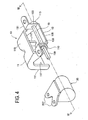
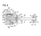
- the hinge member 10 includes a first hinge arm 11 fixed to a floor part 60 defining the lower edge of the rear opening 31, a pin shaft 15 held against rotation by the first hinge arm 11, and a second hinge arm 13 rotatably mounted on the pin shaft 15 and secured to the lower end of the lower door 41, as shown in Figs. 2 to 4 and Fig. 6 .
- Each flange 117 of the horizontal part 115 further extends in the direction opposite the vertical wall 61 and formed at a predetermined position with a hole 1131 (see Fig. 6 ) through which the pin shaft 15 is inserted, thus forming a semicircular shaft-fixing part 113 centered on the hole 1131.
- the hole 1131 on the left side in a vehicle traveling direction has a rectangular shape and the other hole 1131 on the right side has a round shape.
- the rectangular-section portion 155 is formed to have a square section which is coaxial with the pin portion 153 and has four sides each being slightly larger than the diameter of the pin portion 153.
- the rectangular-section portion 155 is engaged in the rectangular hole 1131 formed in one of the shaft fixing parts 113 to inhibit rotation of the pin shaft 15 relative to the first hinge arm 11.
- the flange 157 is larger in diameter than the rectangular-section portion 155 and serves to fix the pin shaft 15 to the first hinge arm 11 in cooperation with the head 151.
- the projecting portion 159 is formed extending by a predetermined length from the flange 157 in a direction opposite the pin portion 153 and having a rectangular section. Specifically, this projecting portion 159 extends outward of the hinge arms 11 and 13 in such a manner as to engage with the damper 20 mentioned later.
- a seal groove 2111 is formed and receives a seal member in slidable contact with the inner periphery of the cap 25.
- the rectangular hole 2131 opens at the outer surface of the disc part 211 and has a depth short of reaching an after-mentioned recess 2133 formed in the shaft 213.
- the circular recess 2133 is formed in the shaft 213 in such a manner as to be opposite the rectangular hole 2131 with respect to the bottom thereof and coaxial with the rectangular hole 2131.
- the housing 23 has a bottomed shape including a cylindrical wall 231, a bottom wall 233 forming the bottom of the cylindrical wall 231, and a fixed vane 235 radially inwardly protruding from the cylindrical wall 231, one end of the fixed vane 235 being continuous to the bottom wall 233 and the other end facing to the opening of the housing 23, and the vane 235 having a height so as to contact with the periphery of the shaft 213 of the rotor 21.
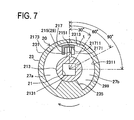
- the inner wall surface 2311 of the cylindrical wall 231 is formed with an eccentric groove 231 having a depth gradually increasing outward from the inner wall surface 2311, the groove 231 being in nearly a diametrically opposite position, as shown in sectional views of Figs. 7 to 9 .
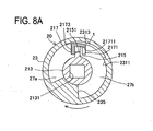
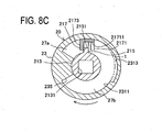
- This eccentric groove 2313 is designed under the following conditions. While the lower door 41 is turned from the almost vertical, full closed position to a full open position at 90° thereto, the sectional area of a clearance "t" between the eccentric groove 2313 and the outer surface of the valve element 217 is maximum as shown in Fig. 7 when the lower door 41 is in a full closed position, the sectional area of the clearance "t” is decreased as the lower door 41 is gradually turned in the opening direction as shown in Figs. 8A to 8C , and the valve element 217 comes to face a portion not provided with the eccentric groove 2313 when the lower door 41 in the full open position ( Fig. 8C ).
- the inner diameter of the inner wall surface 2311 of the cylindrical wall 231 is determined to be almost equal to the outer diameter provided by the outer surface of the valve element 217 when the valve element 217 is mounted to cover the vane 215 of the rotor 21.
- the inner wall surface 2311 is formed, around an opening, with a screw threaded portion which engages with the cap 25 mentioned later.
- the bottom wall 23 is centrally formed with a protrusion 2331 protruding toward the opening at a predetermined height so as to enter in the recess 2133 of the rotor 21.
- the cap 25 is formed in an annular shape having an L-shape in section.
- the disc part 211 of the rotor 21 is hermetically fitted with the seal member inserted in the seal groove 2111.
- the outer surface around the aperture is formed with a male screw threaded portion which engages with the screw threaded portion of the opening area of the inner wall surface 2311 of the housing 23 and a flange portion held in contact with the end face around the opening of the housing 23.
- stays 237 for attachment of the housing 23 to the lower end of the door 41 are formed protruding in Y-shape in parallel to the central axis.
- the damper 20 is attached to be flush with the lower end of the lower door 41 to which the second hinge arm 13 of the hinge member 10 is attached. Accordingly, the distance from the center of the shaft 213 of the rotor 21 to the outer surfaces of the stays 237 is determined to be equal to the distance from the center of the pin shaft 15 of the second hinge arm 13 to the mounting surfaces of the lugs 131.
- each hinge arm 11 is attached to the floor part 60 and each second hinge arm 13 is attached to the lower end of the lower door 41.
- the damper 20 is mounted on the lower end of the lower door 41 by use of the stays 237 of the damper 20, adjacently to the hinge member 10, when the projecting portion 159 extending from the pin shaft 15 of the hinge member 10, which is placed on the right side in the vehicle traveling direction, toward the center of the vehicle is inserted in the rectangular hole 2131 provided in the center of the rotor 21 of the damper 20.
- those hinge member 10 and damper 20 constitute the vehicle door opening/closing device 1.
- the lower door 41 is provided, as with a conventional structure, with a torsion spring (the same as that in Fig. 10 ) serving as a support means for assisting the power to lift the lower door 41 in order to close the lower door 41 from the full open position, a board 70 disposed to automatically close a gap between the floor part 60 and the lower door 41 when the lower door 41 is fully closed, and others.
- a torsion spring (the same as that in Fig. 10 ) serving as a support means for assisting the power to lift the lower door 41 in order to close the lower door 41 from the full open position
- a board 70 disposed to automatically close a gap between the floor part 60 and the lower door 41 when the lower door 41 is fully closed, and others.
- the housing 23 is in a position where the clearance "t" is large between the eccentric groove 2313 and the valve element 217.
- the oil chambers 27a and 27b partitioned by the rotor 21 and the valve element 217 are communicated to each other through the passage defined by the cutouts 21711 and 2151.
- the viscous fluid 299 is therefore allowed to easily move.
- the housing 23 is in a position where the clearance "t" between the eccentric groove 2313 and the valve element 217 is smaller. Accordingly, the viscous fluid 299 existing in the oil chamber 27b is allowed to flow in the oil chamber 27a through only the clearance "t". Thus, resistance in opening the lower door 41 is still small.
- the vehicle door opening/closing device of the present embodiment is arranged such that the hinge member 10 includes the first hinge arm 11 fixed to the floor 60, the pin shaft 15 fixed to the first hinge arm 11 and protruding outward of the first hinge arm 11, and the second hinge arm 13 pivotally mounted on the pin shaft 15 and fixed to the lower end of the lower door 41; and the damper 20 includes the rotor 21 connected to the projecting portion 159 of the pin shaft 15, the housing 23 rotatably mounted on the rotor 21 and fixed to the lower door 41, and the braking means 29 contained in the housing 23 and arranged to impart the braking force to the housing 23 when rotated relative to the rotor 21. Since such a hinge member including the pin shaft provided with the projecting portion is used, a simple configuration that the rotor of the damper is connected to the projecting portion can improve an opening and closing feeling of the lower door.
- the present invention is not limited to the above embodiment and may be embodied in other specific forms without departing from the essential characteristics thereof.
- the above embodiment shows the case where the damper is connected to one of the hinge members.
- the damper may be provided for each of the hinge members or only the left one.
- the housing of the damper may be fixed to the floor so that the rotor is rotated in synchronization with the door.
- the eccentric groove of the damper is provided in the housing.
- the shaft of the rotor may be provided with an eccentric groove to control the flow of viscous fluid.
- the present invention is a vehicle door opening/closing device including a hinge member for pivotally connecting a door for opening/closing an opening of a vehicle body to the vehicle body, and a damper for imparting a braking force to the door when the door is turned relative to the vehicle body.
- the hinge member includes a first hinge arm to be attached to one of an edge of the opening and an end of the door facing to each other, a pin shaft fixed to the first hinge arm to be placed along the edge of the opening and the end of the door, and a second hinge arm pivotally mounted on the pin shaft and to be attached to the other of the edge of the opening and the end of the door.
- the damper includes a rotor connected to the pin shaft, a housing rotatably mounted on the rotor and to be attached to the one of the vehicle body and the door, and a braking means contained in the housing and arranged to impart a braking force to the housing when the housing is rotated relative to the rotor. Accordingly, the damper is disposed on the axis of the pin shaft of the hinge member between the edge of the opening and the edge of the door.
Landscapes
- Engineering & Computer Science (AREA)
- Mechanical Engineering (AREA)
- Fluid-Damping Devices (AREA)
- Closing And Opening Devices For Wings, And Checks For Wings (AREA)
Claims (2)
- Fahrzeugtüröffnungs/schließvorrichtung (1) einschließlich eines Scharnierelements (10), um eine Tür (41) zum Öffnen und Schließen einer Öffnung (31) einer Fahrzeugkarosserie (30) schwenkbar mit der Fahrzeugkarosserie zu verbinden, und eines Dämpfers (20) zum Aufbringen einer Bremskraft auf die Tür, wenn die Tür relativ zu der Fahrzeugkarosserie gedreht wird,
wobei das Scharnierelement (10) Folgendes aufweist:einen ersten Scharnierarm (11), der entweder an einer Kante der Öffnung (31) oder an einem Ende der Tür (41) anzubringen ist, die einander zugewandt sind;eine Stiftwelle (15), die an dem ersten Scharnierarm so befestigt ist, dass sie entlang der Kante der Öffnung und des Endes der Tür platziert ist; undeinen zweiten Scharnierarm (13), der an der Stiftwelle (15) schwenkbar angebracht und an dem anderen von der Kante der Öffnung und dem Ende der Tür anzubringen ist, undwobei der Dämpfer (20) Folgendes aufweist:einen Rotor (21), der mit der Stiftwelle verbunden ist; ein Gehäuse (23), das drehbar an dem Rotor angebracht und an dem anderen von der Fahrzeugkarosserie und der Tür anzubringen ist;eine Bremseinrichtung (29), die in dem Gehäuse enthalten ist und dazu eingerichtet ist, eine Bremskraft auf das Gehäuse aufzubringen, wenn das Gehäuse relativ zu dem Rotor gedreht wird, undwobei das Scharnierelement (10) dazu eingerichtet ist, ein unteres Ende der Tür (41) mit der Fahrzeugkarosserie (30) derart zu verbinden, dass die Tür (41) nach oben und nach unten gedreht werden kann,dadurch gekennzeichnet, dass
der Dämpfer (20) dazu eingerichtet ist, die Bremskraft zu erhöhen, wenn die Tür (41) in eine Öffnungsrichtung gedreht wird,
wobei der Dämpfer (20) einen Ausschnitt (2151), der in einem Flügel (215) des Rotors (21) ausgebildet ist, und ein Ventilelement (217) mit einer Türform im Schnitt aufweist, wobei das Ventilelement den Flügel abdeckt und eine Seitenfläche hat, die mit einem Ausschnitt (21711) an einer Position ausgebildet ist, die dem Ausschnitt des Flügels zugewandt ist,
wobei das Gehäuse (23) im Inneren einen festen Flügel (235) aufweist,
ein viskoses Fluid (299) in dem Gehäuse gefüllt ist, das Ventilelement (217) einen Bodenabschnitt (2175) aufweist, der eine gekrümmte Außenfläche hat, und das Gehäuse (23) mit einer exzentrischen Nut (2313) an einer Position ausgebildet ist, die der Außenfläche des Bodenabschnitts des Gehäuses zugewandt ist,
die exzentrische Nut (2313) für die folgenden Bedingungen ausgelegt ist: Während die Tür (41) von der nahezu vertikalen, vollständig geschlossenen Position zu einer vollständig geöffneten Position um 90° dazu gedreht wird, ist der Querschnittsflächeninhalt eines Zwischenraums (t) zwischen der exzentrischen Nut (2313) und der Außenfläche des Ventilelements (217) maximal, wenn die Tür (41) an einer vollständig geschlossenen Position ist, wobei sich der Querschnittsflächeninhalt des Zwischenraums (t) verkleinert, wenn die Tür (41) allmählich in der Öffnungsrichtung gedreht wird, und das Ventilelement (217) ist dann einem Abschnitt zugewandt, der nicht mit der exzentrischen Nut (2313) versehen ist, wenn die Tür (41) in der vollständig geöffneten Position ist. - Fahrzeugstüröffnungs/schließvorrichtung gemäß Anspruch 1, wobei ein Ende der Stiftwelle (15) einen
Vorsprungsabschnitt (159) bildet, der sich von beiden Scharnierarmen (11, 13) nach Außen erstreckt und mit dem Rotor (21) verbunden ist.
Applications Claiming Priority (2)
| Application Number | Priority Date | Filing Date | Title |
|---|---|---|---|
| JP2005253042A JP4151687B2 (ja) | 2005-09-01 | 2005-09-01 | 車両用ドア開閉装置 |
| PCT/JP2006/315637 WO2007029441A1 (ja) | 2005-09-01 | 2006-08-08 | 車両用ドア開閉装置 |
Publications (3)
| Publication Number | Publication Date |
|---|---|
| EP1921241A1 EP1921241A1 (de) | 2008-05-14 |
| EP1921241A4 EP1921241A4 (de) | 2008-08-20 |
| EP1921241B1 true EP1921241B1 (de) | 2013-03-20 |
Family
ID=37835566
Family Applications (1)
| Application Number | Title | Priority Date | Filing Date |
|---|---|---|---|
| EP06796316A Ceased EP1921241B1 (de) | 2005-09-01 | 2006-08-08 | Öffnungs-/schliessvorrichtung für eine fahrzeugtür |
Country Status (5)
| Country | Link |
|---|---|
| US (1) | US7866001B2 (de) |
| EP (1) | EP1921241B1 (de) |
| JP (1) | JP4151687B2 (de) |
| CN (1) | CN101253301B (de) |
| WO (1) | WO2007029441A1 (de) |
Families Citing this family (29)
| Publication number | Priority date | Publication date | Assignee | Title |
|---|---|---|---|---|
| US8117716B2 (en) * | 2006-06-05 | 2012-02-21 | Shiroki Kogyo Co., Ltd. | One-way valve and door check apparatus |
| US7673929B2 (en) * | 2007-10-10 | 2010-03-09 | Ventra Group, Inc. | Hinge with a viscous rotary damper |
| JP5662111B2 (ja) * | 2010-11-10 | 2015-01-28 | スガツネ工業株式会社 | ダンパ付きヒンジ装置 |
| KR20130115369A (ko) * | 2011-01-20 | 2013-10-21 | 존슨 컨트롤즈 인테리얼즈 게엠베하 앤 컴퍼니 케이지 | 자동차 내부 트림 부품용 이동 장치, 및 내부 트림 부품 |
| CN102619074A (zh) * | 2011-01-28 | 2012-08-01 | 鸿富锦精密工业(深圳)有限公司 | 铰链结构 |
| MX347798B (es) * | 2011-04-12 | 2017-04-27 | Kk Somic Ishikawa | Amortiguador giratorio. |
| US9027979B2 (en) | 2011-04-12 | 2015-05-12 | Kabushiki Kaisha Somic Ishikawa | Rotary damper and opening and closing mechanism for a vehicle door |
| JP2015004387A (ja) * | 2013-06-19 | 2015-01-08 | 株式会社ソミック石川 | ロータリダンパーおよび車両用扉の開閉機構 |
| JP5760812B2 (ja) | 2011-07-28 | 2015-08-12 | オイレス工業株式会社 | トラックのテールゲート用の回転減速装置 |
| US8544930B2 (en) * | 2012-01-27 | 2013-10-01 | Toyota Motor Engineering & Manufacturing North America, Inc. | Tailgate damping systems |
| RU2541562C2 (ru) * | 2013-06-04 | 2015-02-20 | Открытое акционерное общество "Завод им. В.А. Дегтярева" | Распашной борт специального транспортного средства |
| CN103883190B (zh) * | 2014-02-13 | 2016-03-23 | 江苏皓日汽车零部件有限公司 | 后门铰链总成 |
| JP6403592B2 (ja) * | 2014-05-02 | 2018-10-10 | 立川ブラインド工業株式会社 | 遮蔽装置 |
| JP6355447B2 (ja) * | 2014-06-20 | 2018-07-11 | プラス株式会社 | 回転機構、及びそれを用いたケース体 |
| WO2016009881A1 (ja) * | 2014-07-14 | 2016-01-21 | 立川ブラインド工業株式会社 | 遮蔽装置 |
| CN106687658B (zh) | 2014-07-14 | 2020-05-15 | 立川窗饰工业株式会社 | 遮蔽装置 |
| WO2016009880A1 (ja) * | 2014-07-14 | 2016-01-21 | 立川ブラインド工業株式会社 | 遮蔽装置 |
| US9725940B2 (en) * | 2014-07-24 | 2017-08-08 | Michael Lambright | Door hinge closing mechanism |
| TWI576497B (zh) * | 2015-12-04 | 2017-04-01 | Metal Ind Res And Dev Centre | Multi - stage door resistance device |
| US10253556B2 (en) * | 2016-06-29 | 2019-04-09 | Hunter Douglas Inc. | Damper for a covering for an architectural opening |
| FR3053748B1 (fr) * | 2016-07-06 | 2018-07-13 | A Raymond Et Cie | Ensemble de charniere a barre de torsion renforce |
| US10145164B2 (en) | 2016-10-27 | 2018-12-04 | Ford Global Technologies, Llc | Vehicle tailgate assembly |
| CN108556933A (zh) * | 2017-05-03 | 2018-09-21 | 湖北江山专用汽车有限公司 | 一种货运车可拓展车厢 |
| RU184970U1 (ru) * | 2018-07-12 | 2018-11-15 | Евгений Станиславович Фокин | Устройство фокина для облегчения погрузки-разгрузки из каркаса кузова и прицепа грузового автомобиля |
| JP2020180429A (ja) * | 2019-04-23 | 2020-11-05 | 株式会社ハイレックスコーポレーション | 開閉体駆動機構 |
| US11498626B2 (en) * | 2020-11-11 | 2022-11-15 | Rivian Ip Holdings, Llc | Vehicle tailgate assembly |
| US20240123930A1 (en) * | 2022-10-14 | 2024-04-18 | Rivian Ip Holdings, Llc | Vehicle grille guard and tire carrier |
| CN116641611B (zh) * | 2023-06-20 | 2025-11-25 | 重庆长安汽车股份有限公司 | 一种后备箱盖支撑装置、后备箱盖总成以及车辆 |
| CN119686600B (zh) * | 2024-10-12 | 2025-11-04 | 浙江中劦科技有限公司 | 一种汽车门减震用折叠式缓冲块 |
Family Cites Families (17)
| Publication number | Priority date | Publication date | Assignee | Title |
|---|---|---|---|---|
| US1970369A (en) * | 1930-06-10 | 1934-08-14 | Nevin S Focht | Hydraulic shock absorber |
| AU624027B2 (en) * | 1989-10-11 | 1992-05-28 | Sugatsune Industrial Co., Ltd | Door hinge |
| JP2581655B2 (ja) * | 1991-03-08 | 1997-02-12 | トックベアリング株式会社 | 高トルク用ダンパ |
| US5326093A (en) | 1993-05-24 | 1994-07-05 | Xerox Corporation | Universal interface module interconnecting various copiers and printers with various sheet output processors |
| JP2502042Y2 (ja) | 1993-07-14 | 1996-06-19 | トックベアリング株式会社 | ダンピングヒンジ |
| JP3008305U (ja) * | 1994-08-27 | 1995-03-14 | 加藤電機株式会社 | 洋式便器の便蓋や便座等の開閉装置 |
| JPH08303514A (ja) | 1995-04-28 | 1996-11-19 | Sankyo Seiki Mfg Co Ltd | 回転ダンパー装置 |
| US5996132A (en) * | 1997-01-24 | 1999-12-07 | Katoh Electrical Machinery Co., Ltd. | Compound torque hinge |
| JP4573190B2 (ja) * | 2001-06-04 | 2010-11-04 | トックベアリング株式会社 | 回転ダンパ |
| JP3738419B2 (ja) | 2001-10-18 | 2006-01-25 | 株式会社大井製作所 | 車両用開閉体のヒンジ装置、及びこのヒンジ装置を備える開閉装置 |
| CN1240952C (zh) * | 2002-01-23 | 2006-02-08 | 株式会社三协精机制作所 | 使用粘性流体的阻尼器装置及其制造方法 |
| JP3752202B2 (ja) | 2002-07-19 | 2006-03-08 | 株式会社ストロベリーコーポレーション | ヒンジ装置並びにヒンジ装置を用いた電子機器 |
| JP3990611B2 (ja) | 2002-08-22 | 2007-10-17 | 本田技研工業株式会社 | 車両の後部ドア構造 |
| DE20215983U1 (de) * | 2002-10-17 | 2003-02-27 | Lin, Wu-Shiong, Taichung | Türschließer |
| JP2005035365A (ja) | 2003-07-18 | 2005-02-10 | Daihatsu Motor Co Ltd | あおりを有する自動車のあおり用ヒンジ構造 |
| JP4509585B2 (ja) * | 2004-01-26 | 2010-07-21 | 株式会社ニフコ | ダンパ及びこのダンパを備えたドアハンドル |
| DE202006006067U1 (de) * | 2006-04-13 | 2006-06-14 | Edscha Ag | Vorrichtung zum Dämpfen einer Schwenkbewegung |
-
2005
- 2005-09-01 JP JP2005253042A patent/JP4151687B2/ja not_active Expired - Fee Related
-
2006
- 2006-08-08 EP EP06796316A patent/EP1921241B1/de not_active Ceased
- 2006-08-08 WO PCT/JP2006/315637 patent/WO2007029441A1/ja not_active Ceased
- 2006-08-08 CN CN200680031854XA patent/CN101253301B/zh not_active Expired - Fee Related
- 2006-08-08 US US11/990,021 patent/US7866001B2/en not_active Expired - Fee Related
Also Published As
| Publication number | Publication date |
|---|---|
| US20090139057A1 (en) | 2009-06-04 |
| EP1921241A1 (de) | 2008-05-14 |
| JP2007063884A (ja) | 2007-03-15 |
| CN101253301B (zh) | 2013-06-19 |
| US7866001B2 (en) | 2011-01-11 |
| EP1921241A4 (de) | 2008-08-20 |
| WO2007029441A1 (ja) | 2007-03-15 |
| JP4151687B2 (ja) | 2008-09-17 |
| CN101253301A (zh) | 2008-08-27 |
Similar Documents
| Publication | Publication Date | Title |
|---|---|---|
| EP1921241B1 (de) | Öffnungs-/schliessvorrichtung für eine fahrzeugtür | |
| US5724683A (en) | Hinge mechanism for supporting the seat or the seat lid of a toilet bowl | |
| CA1326251C (en) | Automotive door structure | |
| CA2278840C (en) | Fluid-damped automotive door latch actuator | |
| US8689403B2 (en) | Door hinge for motor vehicles | |
| KR19980072349A (ko) | 자동도어 클로우저 유니트 | |
| US20050044661A1 (en) | Door-closing device using a cam | |
| JP4308254B2 (ja) | ダンパー付きヒンジ | |
| JPH11247522A (ja) | ロータリダンパ | |
| KR101333385B1 (ko) | 실린더 장치 | |
| KR100483362B1 (ko) | 현관도어용 유압경첩 | |
| JP4470649B2 (ja) | ダンパ及びそれを用いた自動車ドア用ダンパ付きヒンジ機構 | |
| JP3999678B2 (ja) | ヒンジカートリッジ及びドアヒンジ | |
| JP2906316B2 (ja) | リフトヒンジ等の回転ダンパー | |
| KR100770425B1 (ko) | 가구 힌지용 댐핑 장치 | |
| KR200156791Y1 (ko) | 화장실 도어용 힌지 | |
| JP2971607B2 (ja) | ガススプリング | |
| JPH03129078A (ja) | ダンパ付きドアヒンジ | |
| JP2980616B2 (ja) | シートダンパー | |
| KR200209589Y1 (ko) | 수직형 도어 클로져 | |
| KR100326373B1 (ko) | 차량 후방문의 후방창문 힌지구조 | |
| JP3341244B2 (ja) | リザーバータンク付油圧緩衝器 | |
| KR20030037078A (ko) | 도어 힌지 유니트 | |
| JPH0426276Y2 (de) | ||
| KR840000825B1 (ko) | 문짝정지 기구를 가진 폐문장치의 오프셋 피벗힌지 |
Legal Events
| Date | Code | Title | Description |
|---|---|---|---|
| PUAI | Public reference made under article 153(3) epc to a published international application that has entered the european phase |
Free format text: ORIGINAL CODE: 0009012 |
|
| 17P | Request for examination filed |
Effective date: 20080206 |
|
| AK | Designated contracting states |
Kind code of ref document: A1 Designated state(s): DE FR GB |
|
| A4 | Supplementary search report drawn up and despatched |
Effective date: 20080723 |
|
| RIC1 | Information provided on ipc code assigned before grant |
Ipc: E05F 5/00 20060101ALI20080717BHEP Ipc: E05F 3/14 20060101ALI20080717BHEP Ipc: B60J 5/10 20060101ALI20080717BHEP Ipc: E05D 7/086 20060101AFI20080407BHEP Ipc: E05F 3/20 20060101ALI20080717BHEP Ipc: B62D 33/027 20060101ALI20080717BHEP |
|
| DAX | Request for extension of the european patent (deleted) | ||
| RBV | Designated contracting states (corrected) |
Designated state(s): DE FR GB |
|
| 17Q | First examination report despatched |
Effective date: 20110729 |
|
| REG | Reference to a national code |
Ref country code: DE Ref legal event code: R079 Ref document number: 602006035215 Country of ref document: DE Free format text: PREVIOUS MAIN CLASS: E05D0007086000 Ipc: E05D0011100000 |
|
| RIC1 | Information provided on ipc code assigned before grant |
Ipc: E05F 5/00 20060101ALI20120509BHEP Ipc: E05F 3/14 20060101ALI20120509BHEP Ipc: E05D 11/10 20060101AFI20120509BHEP Ipc: E05F 3/20 20060101ALI20120509BHEP |
|
| GRAP | Despatch of communication of intention to grant a patent |
Free format text: ORIGINAL CODE: EPIDOSNIGR1 |
|
| GRAS | Grant fee paid |
Free format text: ORIGINAL CODE: EPIDOSNIGR3 |
|
| GRAA | (expected) grant |
Free format text: ORIGINAL CODE: 0009210 |
|
| AK | Designated contracting states |
Kind code of ref document: B1 Designated state(s): DE FR GB |
|
| REG | Reference to a national code |
Ref country code: GB Ref legal event code: FG4D |
|
| REG | Reference to a national code |
Ref country code: DE Ref legal event code: R096 Ref document number: 602006035215 Country of ref document: DE Effective date: 20130508 |
|
| PLBE | No opposition filed within time limit |
Free format text: ORIGINAL CODE: 0009261 |
|
| STAA | Information on the status of an ep patent application or granted ep patent |
Free format text: STATUS: NO OPPOSITION FILED WITHIN TIME LIMIT |
|
| 26N | No opposition filed |
Effective date: 20140102 |
|
| REG | Reference to a national code |
Ref country code: DE Ref legal event code: R097 Ref document number: 602006035215 Country of ref document: DE Effective date: 20140102 |
|
| REG | Reference to a national code |
Ref country code: FR Ref legal event code: PLFP Year of fee payment: 11 |
|
| REG | Reference to a national code |
Ref country code: FR Ref legal event code: PLFP Year of fee payment: 12 |
|
| REG | Reference to a national code |
Ref country code: FR Ref legal event code: PLFP Year of fee payment: 13 |
|
| PGFP | Annual fee paid to national office [announced via postgrant information from national office to epo] |
Ref country code: DE Payment date: 20180724 Year of fee payment: 13 Ref country code: FR Payment date: 20180712 Year of fee payment: 13 |
|
| PGFP | Annual fee paid to national office [announced via postgrant information from national office to epo] |
Ref country code: GB Payment date: 20180808 Year of fee payment: 13 |
|
| REG | Reference to a national code |
Ref country code: DE Ref legal event code: R119 Ref document number: 602006035215 Country of ref document: DE |
|
| GBPC | Gb: european patent ceased through non-payment of renewal fee |
Effective date: 20190808 |
|
| PG25 | Lapsed in a contracting state [announced via postgrant information from national office to epo] |
Ref country code: DE Free format text: LAPSE BECAUSE OF NON-PAYMENT OF DUE FEES Effective date: 20200303 Ref country code: FR Free format text: LAPSE BECAUSE OF NON-PAYMENT OF DUE FEES Effective date: 20190831 |
|
| PG25 | Lapsed in a contracting state [announced via postgrant information from national office to epo] |
Ref country code: GB Free format text: LAPSE BECAUSE OF NON-PAYMENT OF DUE FEES Effective date: 20190808 |