EP1920987A2 - Nutzfahrzeug und Leistungssteuerungsverfahren dafür - Google Patents
Nutzfahrzeug und Leistungssteuerungsverfahren dafür Download PDFInfo
- Publication number
- EP1920987A2 EP1920987A2 EP07120014A EP07120014A EP1920987A2 EP 1920987 A2 EP1920987 A2 EP 1920987A2 EP 07120014 A EP07120014 A EP 07120014A EP 07120014 A EP07120014 A EP 07120014A EP 1920987 A2 EP1920987 A2 EP 1920987A2
- Authority
- EP
- European Patent Office
- Prior art keywords
- power
- motor
- running
- unit
- engine
- Prior art date
- Legal status (The legal status is an assumption and is not a legal conclusion. Google has not performed a legal analysis and makes no representation as to the accuracy of the status listed.)
- Granted
Links
Images



Classifications
-
- B—PERFORMING OPERATIONS; TRANSPORTING
- B60—VEHICLES IN GENERAL
- B60W—CONJOINT CONTROL OF VEHICLE SUB-UNITS OF DIFFERENT TYPE OR DIFFERENT FUNCTION; CONTROL SYSTEMS SPECIALLY ADAPTED FOR HYBRID VEHICLES; ROAD VEHICLE DRIVE CONTROL SYSTEMS FOR PURPOSES NOT RELATED TO THE CONTROL OF A PARTICULAR SUB-UNIT
- B60W20/00—Control systems specially adapted for hybrid vehicles
- B60W20/10—Controlling the power contribution of each of the prime movers to meet required power demand
-
- B—PERFORMING OPERATIONS; TRANSPORTING
- B60—VEHICLES IN GENERAL
- B60K—ARRANGEMENT OR MOUNTING OF PROPULSION UNITS OR OF TRANSMISSIONS IN VEHICLES; ARRANGEMENT OR MOUNTING OF PLURAL DIVERSE PRIME-MOVERS IN VEHICLES; AUXILIARY DRIVES FOR VEHICLES; INSTRUMENTATION OR DASHBOARDS FOR VEHICLES; ARRANGEMENTS IN CONNECTION WITH COOLING, AIR INTAKE, GAS EXHAUST OR FUEL SUPPLY OF PROPULSION UNITS IN VEHICLES
- B60K6/00—Arrangement or mounting of plural diverse prime-movers for mutual or common propulsion, e.g. hybrid propulsion systems comprising electric motors and internal combustion engines
- B60K6/20—Arrangement or mounting of plural diverse prime-movers for mutual or common propulsion, e.g. hybrid propulsion systems comprising electric motors and internal combustion engines the prime-movers consisting of electric motors and internal combustion engines, e.g. HEVs
- B60K6/42—Arrangement or mounting of plural diverse prime-movers for mutual or common propulsion, e.g. hybrid propulsion systems comprising electric motors and internal combustion engines the prime-movers consisting of electric motors and internal combustion engines, e.g. HEVs characterised by the architecture of the hybrid electric vehicle
-
- B—PERFORMING OPERATIONS; TRANSPORTING
- B60—VEHICLES IN GENERAL
- B60K—ARRANGEMENT OR MOUNTING OF PROPULSION UNITS OR OF TRANSMISSIONS IN VEHICLES; ARRANGEMENT OR MOUNTING OF PLURAL DIVERSE PRIME-MOVERS IN VEHICLES; AUXILIARY DRIVES FOR VEHICLES; INSTRUMENTATION OR DASHBOARDS FOR VEHICLES; ARRANGEMENTS IN CONNECTION WITH COOLING, AIR INTAKE, GAS EXHAUST OR FUEL SUPPLY OF PROPULSION UNITS IN VEHICLES
- B60K6/00—Arrangement or mounting of plural diverse prime-movers for mutual or common propulsion, e.g. hybrid propulsion systems comprising electric motors and internal combustion engines
- B60K6/20—Arrangement or mounting of plural diverse prime-movers for mutual or common propulsion, e.g. hybrid propulsion systems comprising electric motors and internal combustion engines the prime-movers consisting of electric motors and internal combustion engines, e.g. HEVs
- B60K6/42—Arrangement or mounting of plural diverse prime-movers for mutual or common propulsion, e.g. hybrid propulsion systems comprising electric motors and internal combustion engines the prime-movers consisting of electric motors and internal combustion engines, e.g. HEVs characterised by the architecture of the hybrid electric vehicle
- B60K6/48—Parallel type
-
- B—PERFORMING OPERATIONS; TRANSPORTING
- B60—VEHICLES IN GENERAL
- B60K—ARRANGEMENT OR MOUNTING OF PROPULSION UNITS OR OF TRANSMISSIONS IN VEHICLES; ARRANGEMENT OR MOUNTING OF PLURAL DIVERSE PRIME-MOVERS IN VEHICLES; AUXILIARY DRIVES FOR VEHICLES; INSTRUMENTATION OR DASHBOARDS FOR VEHICLES; ARRANGEMENTS IN CONNECTION WITH COOLING, AIR INTAKE, GAS EXHAUST OR FUEL SUPPLY OF PROPULSION UNITS IN VEHICLES
- B60K17/00—Arrangement or mounting of transmissions in vehicles
-
- B—PERFORMING OPERATIONS; TRANSPORTING
- B60—VEHICLES IN GENERAL
- B60L—PROPULSION OF ELECTRICALLY-PROPELLED VEHICLES; SUPPLYING ELECTRIC POWER FOR AUXILIARY EQUIPMENT OF ELECTRICALLY-PROPELLED VEHICLES; ELECTRODYNAMIC BRAKE SYSTEMS FOR VEHICLES IN GENERAL; MAGNETIC SUSPENSION OR LEVITATION FOR VEHICLES; MONITORING OPERATING VARIABLES OF ELECTRICALLY-PROPELLED VEHICLES; ELECTRIC SAFETY DEVICES FOR ELECTRICALLY-PROPELLED VEHICLES
- B60L1/00—Supplying electric power to auxiliary equipment of vehicles
- B60L1/20—Energy regeneration from auxiliary equipment
-
- B—PERFORMING OPERATIONS; TRANSPORTING
- B60—VEHICLES IN GENERAL
- B60L—PROPULSION OF ELECTRICALLY-PROPELLED VEHICLES; SUPPLYING ELECTRIC POWER FOR AUXILIARY EQUIPMENT OF ELECTRICALLY-PROPELLED VEHICLES; ELECTRODYNAMIC BRAKE SYSTEMS FOR VEHICLES IN GENERAL; MAGNETIC SUSPENSION OR LEVITATION FOR VEHICLES; MONITORING OPERATING VARIABLES OF ELECTRICALLY-PROPELLED VEHICLES; ELECTRIC SAFETY DEVICES FOR ELECTRICALLY-PROPELLED VEHICLES
- B60L50/00—Electric propulsion with power supplied within the vehicle
- B60L50/10—Electric propulsion with power supplied within the vehicle using propulsion power supplied by engine-driven generators, e.g. generators driven by combustion engines
- B60L50/16—Electric propulsion with power supplied within the vehicle using propulsion power supplied by engine-driven generators, e.g. generators driven by combustion engines with provision for separate direct mechanical propulsion
-
- B—PERFORMING OPERATIONS; TRANSPORTING
- B60—VEHICLES IN GENERAL
- B60L—PROPULSION OF ELECTRICALLY-PROPELLED VEHICLES; SUPPLYING ELECTRIC POWER FOR AUXILIARY EQUIPMENT OF ELECTRICALLY-PROPELLED VEHICLES; ELECTRODYNAMIC BRAKE SYSTEMS FOR VEHICLES IN GENERAL; MAGNETIC SUSPENSION OR LEVITATION FOR VEHICLES; MONITORING OPERATING VARIABLES OF ELECTRICALLY-PROPELLED VEHICLES; ELECTRIC SAFETY DEVICES FOR ELECTRICALLY-PROPELLED VEHICLES
- B60L50/00—Electric propulsion with power supplied within the vehicle
- B60L50/50—Electric propulsion with power supplied within the vehicle using propulsion power supplied by batteries or fuel cells
- B60L50/60—Electric propulsion with power supplied within the vehicle using propulsion power supplied by batteries or fuel cells using power supplied by batteries
- B60L50/61—Electric propulsion with power supplied within the vehicle using propulsion power supplied by batteries or fuel cells using power supplied by batteries by batteries charged by engine-driven generators, e.g. series hybrid electric vehicles
-
- B—PERFORMING OPERATIONS; TRANSPORTING
- B60—VEHICLES IN GENERAL
- B60W—CONJOINT CONTROL OF VEHICLE SUB-UNITS OF DIFFERENT TYPE OR DIFFERENT FUNCTION; CONTROL SYSTEMS SPECIALLY ADAPTED FOR HYBRID VEHICLES; ROAD VEHICLE DRIVE CONTROL SYSTEMS FOR PURPOSES NOT RELATED TO THE CONTROL OF A PARTICULAR SUB-UNIT
- B60W10/00—Conjoint control of vehicle sub-units of different type or different function
- B60W10/02—Conjoint control of vehicle sub-units of different type or different function including control of driveline clutches
-
- B—PERFORMING OPERATIONS; TRANSPORTING
- B60—VEHICLES IN GENERAL
- B60W—CONJOINT CONTROL OF VEHICLE SUB-UNITS OF DIFFERENT TYPE OR DIFFERENT FUNCTION; CONTROL SYSTEMS SPECIALLY ADAPTED FOR HYBRID VEHICLES; ROAD VEHICLE DRIVE CONTROL SYSTEMS FOR PURPOSES NOT RELATED TO THE CONTROL OF A PARTICULAR SUB-UNIT
- B60W10/00—Conjoint control of vehicle sub-units of different type or different function
- B60W10/04—Conjoint control of vehicle sub-units of different type or different function including control of propulsion units
- B60W10/06—Conjoint control of vehicle sub-units of different type or different function including control of propulsion units including control of combustion engines
-
- B—PERFORMING OPERATIONS; TRANSPORTING
- B60—VEHICLES IN GENERAL
- B60W—CONJOINT CONTROL OF VEHICLE SUB-UNITS OF DIFFERENT TYPE OR DIFFERENT FUNCTION; CONTROL SYSTEMS SPECIALLY ADAPTED FOR HYBRID VEHICLES; ROAD VEHICLE DRIVE CONTROL SYSTEMS FOR PURPOSES NOT RELATED TO THE CONTROL OF A PARTICULAR SUB-UNIT
- B60W10/00—Conjoint control of vehicle sub-units of different type or different function
- B60W10/04—Conjoint control of vehicle sub-units of different type or different function including control of propulsion units
- B60W10/08—Conjoint control of vehicle sub-units of different type or different function including control of propulsion units including control of electric propulsion units, e.g. motors or generators
-
- B—PERFORMING OPERATIONS; TRANSPORTING
- B60—VEHICLES IN GENERAL
- B60W—CONJOINT CONTROL OF VEHICLE SUB-UNITS OF DIFFERENT TYPE OR DIFFERENT FUNCTION; CONTROL SYSTEMS SPECIALLY ADAPTED FOR HYBRID VEHICLES; ROAD VEHICLE DRIVE CONTROL SYSTEMS FOR PURPOSES NOT RELATED TO THE CONTROL OF A PARTICULAR SUB-UNIT
- B60W10/00—Conjoint control of vehicle sub-units of different type or different function
- B60W10/30—Conjoint control of vehicle sub-units of different type or different function including control of auxiliary equipment, e.g. air-conditioning compressors or oil pumps
-
- B—PERFORMING OPERATIONS; TRANSPORTING
- B60—VEHICLES IN GENERAL
- B60W—CONJOINT CONTROL OF VEHICLE SUB-UNITS OF DIFFERENT TYPE OR DIFFERENT FUNCTION; CONTROL SYSTEMS SPECIALLY ADAPTED FOR HYBRID VEHICLES; ROAD VEHICLE DRIVE CONTROL SYSTEMS FOR PURPOSES NOT RELATED TO THE CONTROL OF A PARTICULAR SUB-UNIT
- B60W20/00—Control systems specially adapted for hybrid vehicles
-
- B—PERFORMING OPERATIONS; TRANSPORTING
- B66—HOISTING; LIFTING; HAULING
- B66F—HOISTING, LIFTING, HAULING OR PUSHING, NOT OTHERWISE PROVIDED FOR, e.g. DEVICES WHICH APPLY A LIFTING OR PUSHING FORCE DIRECTLY TO THE SURFACE OF A LOAD
- B66F9/00—Devices for lifting or lowering bulky or heavy goods for loading or unloading purposes
- B66F9/06—Devices for lifting or lowering bulky or heavy goods for loading or unloading purposes movable, with their loads, on wheels or the like, e.g. fork-lift trucks
- B66F9/075—Constructional features or details
- B66F9/20—Means for actuating or controlling masts, platforms, or forks
-
- B—PERFORMING OPERATIONS; TRANSPORTING
- B60—VEHICLES IN GENERAL
- B60L—PROPULSION OF ELECTRICALLY-PROPELLED VEHICLES; SUPPLYING ELECTRIC POWER FOR AUXILIARY EQUIPMENT OF ELECTRICALLY-PROPELLED VEHICLES; ELECTRODYNAMIC BRAKE SYSTEMS FOR VEHICLES IN GENERAL; MAGNETIC SUSPENSION OR LEVITATION FOR VEHICLES; MONITORING OPERATING VARIABLES OF ELECTRICALLY-PROPELLED VEHICLES; ELECTRIC SAFETY DEVICES FOR ELECTRICALLY-PROPELLED VEHICLES
- B60L2200/00—Type of vehicles
- B60L2200/40—Working vehicles
- B60L2200/42—Fork lift trucks
-
- B—PERFORMING OPERATIONS; TRANSPORTING
- B60—VEHICLES IN GENERAL
- B60L—PROPULSION OF ELECTRICALLY-PROPELLED VEHICLES; SUPPLYING ELECTRIC POWER FOR AUXILIARY EQUIPMENT OF ELECTRICALLY-PROPELLED VEHICLES; ELECTRODYNAMIC BRAKE SYSTEMS FOR VEHICLES IN GENERAL; MAGNETIC SUSPENSION OR LEVITATION FOR VEHICLES; MONITORING OPERATING VARIABLES OF ELECTRICALLY-PROPELLED VEHICLES; ELECTRIC SAFETY DEVICES FOR ELECTRICALLY-PROPELLED VEHICLES
- B60L2240/00—Control parameters of input or output; Target parameters
- B60L2240/40—Drive Train control parameters
- B60L2240/48—Drive Train control parameters related to transmissions
- B60L2240/486—Operating parameters
-
- B—PERFORMING OPERATIONS; TRANSPORTING
- B60—VEHICLES IN GENERAL
- B60W—CONJOINT CONTROL OF VEHICLE SUB-UNITS OF DIFFERENT TYPE OR DIFFERENT FUNCTION; CONTROL SYSTEMS SPECIALLY ADAPTED FOR HYBRID VEHICLES; ROAD VEHICLE DRIVE CONTROL SYSTEMS FOR PURPOSES NOT RELATED TO THE CONTROL OF A PARTICULAR SUB-UNIT
- B60W2510/00—Input parameters relating to a particular sub-units
- B60W2510/24—Energy storage means
- B60W2510/242—Energy storage means for electrical energy
- B60W2510/244—Charge state
-
- B—PERFORMING OPERATIONS; TRANSPORTING
- B60—VEHICLES IN GENERAL
- B60W—CONJOINT CONTROL OF VEHICLE SUB-UNITS OF DIFFERENT TYPE OR DIFFERENT FUNCTION; CONTROL SYSTEMS SPECIALLY ADAPTED FOR HYBRID VEHICLES; ROAD VEHICLE DRIVE CONTROL SYSTEMS FOR PURPOSES NOT RELATED TO THE CONTROL OF A PARTICULAR SUB-UNIT
- B60W2540/00—Input parameters relating to occupants
- B60W2540/10—Accelerator pedal position
-
- B—PERFORMING OPERATIONS; TRANSPORTING
- B60—VEHICLES IN GENERAL
- B60W—CONJOINT CONTROL OF VEHICLE SUB-UNITS OF DIFFERENT TYPE OR DIFFERENT FUNCTION; CONTROL SYSTEMS SPECIALLY ADAPTED FOR HYBRID VEHICLES; ROAD VEHICLE DRIVE CONTROL SYSTEMS FOR PURPOSES NOT RELATED TO THE CONTROL OF A PARTICULAR SUB-UNIT
- B60W2540/00—Input parameters relating to occupants
- B60W2540/12—Brake pedal position
-
- B—PERFORMING OPERATIONS; TRANSPORTING
- B60—VEHICLES IN GENERAL
- B60W—CONJOINT CONTROL OF VEHICLE SUB-UNITS OF DIFFERENT TYPE OR DIFFERENT FUNCTION; CONTROL SYSTEMS SPECIALLY ADAPTED FOR HYBRID VEHICLES; ROAD VEHICLE DRIVE CONTROL SYSTEMS FOR PURPOSES NOT RELATED TO THE CONTROL OF A PARTICULAR SUB-UNIT
- B60W2710/00—Output or target parameters relating to a particular sub-units
- B60W2710/06—Combustion engines, Gas turbines
- B60W2710/0677—Engine power
-
- B—PERFORMING OPERATIONS; TRANSPORTING
- B60—VEHICLES IN GENERAL
- B60W—CONJOINT CONTROL OF VEHICLE SUB-UNITS OF DIFFERENT TYPE OR DIFFERENT FUNCTION; CONTROL SYSTEMS SPECIALLY ADAPTED FOR HYBRID VEHICLES; ROAD VEHICLE DRIVE CONTROL SYSTEMS FOR PURPOSES NOT RELATED TO THE CONTROL OF A PARTICULAR SUB-UNIT
- B60W2710/00—Output or target parameters relating to a particular sub-units
- B60W2710/10—Change speed gearings
- B60W2710/1061—Output power
-
- B—PERFORMING OPERATIONS; TRANSPORTING
- B60—VEHICLES IN GENERAL
- B60Y—INDEXING SCHEME RELATING TO ASPECTS CROSS-CUTTING VEHICLE TECHNOLOGY
- B60Y2200/00—Type of vehicle
- B60Y2200/10—Road Vehicles
- B60Y2200/15—Fork lift trucks, Industrial trucks
-
- Y—GENERAL TAGGING OF NEW TECHNOLOGICAL DEVELOPMENTS; GENERAL TAGGING OF CROSS-SECTIONAL TECHNOLOGIES SPANNING OVER SEVERAL SECTIONS OF THE IPC; TECHNICAL SUBJECTS COVERED BY FORMER USPC CROSS-REFERENCE ART COLLECTIONS [XRACs] AND DIGESTS
- Y02—TECHNOLOGIES OR APPLICATIONS FOR MITIGATION OR ADAPTATION AGAINST CLIMATE CHANGE
- Y02P—CLIMATE CHANGE MITIGATION TECHNOLOGIES IN THE PRODUCTION OR PROCESSING OF GOODS
- Y02P90/00—Enabling technologies with a potential contribution to greenhouse gas [GHG] emissions mitigation
- Y02P90/60—Electric or hybrid propulsion means for production processes
-
- Y—GENERAL TAGGING OF NEW TECHNOLOGICAL DEVELOPMENTS; GENERAL TAGGING OF CROSS-SECTIONAL TECHNOLOGIES SPANNING OVER SEVERAL SECTIONS OF THE IPC; TECHNICAL SUBJECTS COVERED BY FORMER USPC CROSS-REFERENCE ART COLLECTIONS [XRACs] AND DIGESTS
- Y02—TECHNOLOGIES OR APPLICATIONS FOR MITIGATION OR ADAPTATION AGAINST CLIMATE CHANGE
- Y02T—CLIMATE CHANGE MITIGATION TECHNOLOGIES RELATED TO TRANSPORTATION
- Y02T10/00—Road transport of goods or passengers
- Y02T10/10—Internal combustion engine [ICE] based vehicles
- Y02T10/40—Engine management systems
-
- Y—GENERAL TAGGING OF NEW TECHNOLOGICAL DEVELOPMENTS; GENERAL TAGGING OF CROSS-SECTIONAL TECHNOLOGIES SPANNING OVER SEVERAL SECTIONS OF THE IPC; TECHNICAL SUBJECTS COVERED BY FORMER USPC CROSS-REFERENCE ART COLLECTIONS [XRACs] AND DIGESTS
- Y02—TECHNOLOGIES OR APPLICATIONS FOR MITIGATION OR ADAPTATION AGAINST CLIMATE CHANGE
- Y02T—CLIMATE CHANGE MITIGATION TECHNOLOGIES RELATED TO TRANSPORTATION
- Y02T10/00—Road transport of goods or passengers
- Y02T10/60—Other road transportation technologies with climate change mitigation effect
- Y02T10/62—Hybrid vehicles
-
- Y—GENERAL TAGGING OF NEW TECHNOLOGICAL DEVELOPMENTS; GENERAL TAGGING OF CROSS-SECTIONAL TECHNOLOGIES SPANNING OVER SEVERAL SECTIONS OF THE IPC; TECHNICAL SUBJECTS COVERED BY FORMER USPC CROSS-REFERENCE ART COLLECTIONS [XRACs] AND DIGESTS
- Y02—TECHNOLOGIES OR APPLICATIONS FOR MITIGATION OR ADAPTATION AGAINST CLIMATE CHANGE
- Y02T—CLIMATE CHANGE MITIGATION TECHNOLOGIES RELATED TO TRANSPORTATION
- Y02T10/00—Road transport of goods or passengers
- Y02T10/60—Other road transportation technologies with climate change mitigation effect
- Y02T10/70—Energy storage systems for electromobility, e.g. batteries
-
- Y—GENERAL TAGGING OF NEW TECHNOLOGICAL DEVELOPMENTS; GENERAL TAGGING OF CROSS-SECTIONAL TECHNOLOGIES SPANNING OVER SEVERAL SECTIONS OF THE IPC; TECHNICAL SUBJECTS COVERED BY FORMER USPC CROSS-REFERENCE ART COLLECTIONS [XRACs] AND DIGESTS
- Y02—TECHNOLOGIES OR APPLICATIONS FOR MITIGATION OR ADAPTATION AGAINST CLIMATE CHANGE
- Y02T—CLIMATE CHANGE MITIGATION TECHNOLOGIES RELATED TO TRANSPORTATION
- Y02T10/00—Road transport of goods or passengers
- Y02T10/60—Other road transportation technologies with climate change mitigation effect
- Y02T10/7072—Electromobility specific charging systems or methods for batteries, ultracapacitors, supercapacitors or double-layer capacitors
Definitions
- the present invention relates to industrial vehicles and to a method for controlling power of the same.
- Hybrid systems include series systems that supply power to a running system and a loading-and-unloading system by generating electrical power from a generator rotationally driven by an engine and supplying the obtained electrical power to an electric motor; and parallel systems that supply at least a part of the engine power, as well as power from the electric motor, to the running system and the loading-and-unloading system.
- Japanese Unexamined Patent Application, Publication No. 2003-250203 discloses hybrid industrial vehicles for loading and unloading configured to supply power to a running system using a series system, and to a loading-and-unloading system using a parallel system.
- Japanese Unexamined Patent Application, Publication No. 2000-313600 discloses running vehicles having a loading-and-unloading function configured to supply power to a running system and a loading-and-unloading system using a series system.
- the total power generated from the engine and the electric motor is equal to the total power supplied to the running system and the loading-and-unloading system (power balance is satisfied).
- the ratio of power generated by the engine to power generated by the electric motor is usually determined by a torque distribution to the engine and the electric motor.
- a rotation speed of the engine and a rotation speed of the electric motor arbitrarily change with the torque distribution, and rotation speeds of the engine and the electric motor, as well as the torque, are also variables. Therefore, it is complicated to perform control involving many variables for setting the torque so as to satisfy the engine power balance.
- the present invention has been conceived to solve the above-described problems, and an object thereof is to provide an industrial vehicle having a hybrid system capable of readily controlling a distribution of power generated by an engine and power generated by an electric motor, and a method of controlling the power of the same.
- the present invention provides the following solutions.
- a first aspect of the present invention is an industrial vehicle comprising an engine configured to supply power to one of a running unit for running and a loading-and-unloading unit for loading and unloading; a first motor configured to supply power to one of the running unit and the loading-and-unloading unit; a second motor configured to supply power to the running unit; a required-power calculating unit configured to calculate running power required by the running unit, and loading-and-unloading power required by the loading-and-unloading unit; a clutch unit configured to control the power transmitted from the engine to the running unit; and a power-distribution calculating unit configured to select a destination to be supplied with power form the engine and the first motor based on the control status of the clutch unit and to calculate a distribution of power which the engine, the first motor, and the second motor supply based on the calculated running power and loading-and-unloading power.
- the power-distribution calculating unit calculates three variables, that is, power which the engine supplies, power which the first motor supplies, and power which the second motor supplies, so as to satisfy the total of running power and loading-and-unloading power, the number of variables can be reduced compared to a distribution method based on torque distribution using many variables. Accordingly, the distribution control can be simplified.
- the destination to be supplied with power from the engine and the first-motor power is selected as either the running unit or the loading-and-unloading unit based on the control status of the clutch unit, thus further simplifying the power distribution control.
- the power distribution of the power which the engine supplies, the power which the first motor supplies, and the power which the second motor supplies is determined according to the required running power and loading-and unloading power, the power distribution can be determined so as to obtain the same operability as industrial vehicles used, for example, in loading and unloading operations, which have only an engine or a motor as a power source.
- the power can be used without waste, thus improving the fuel efficiency of the engine and reducing battery consumption.
- a plurality of sets of table data be provided in the power-distribution calculating unit, wherein the destination to be supplied with power from the engine and power from the first motor is selected based on a control status of the clutch unit, and the distribution of power which the engine supplies, power which the first motor supplies, and power which the second motor supplies is defined based on the calculated running power and loading-and unloading power; and the table data used for distributing the power be changed based on the control status of the clutch unit.
- the table data for setting the power distribution is stored in advance in the power-distribution calculating unit. It is possible to reduce the computational load for the power distribution, thus allowing a reduction in the computational time.
- the clutch unit transmits the power to the running unit
- the engine power and the first-motor power are transmitted to the running unit
- the clutch unit blocks the transmission power to the running unit the engine power and the first-motor power are transmitted to the loading-and-unloading unit, and the power is thus used without waste.
- the power distribution of the first motor and the second motor which have less battery consumption, is set to be high, and when the required running power is large, the power distribution of the fuel efficient engine is set to be high, thus allowing the power to be used without waste.
- a velocity detection unit configured to detect a running velocity is further provided, wherein the plurality of sets of table data determine the distribution of the power which the engine supplies, the power which the first motor supplies, and the power which the second motor supplies also based on an output of the velocity detection unit.
- a battery configured to supply electrical power to a running motor and a loading-and-unloading motor, and a voltage detection unit configured to detect a voltage of the battery be further provided, wherein the plurality sets of table data preferably determine the distribution of the power which the engine supplies, the power which the first motor supplies, and the power which the second motor supplies also based on an output of the voltage detection unit.
- a second aspect of the present invention is a power control method for an industrial vehicle including a required power calculating step of calculating, based on an operation by an operator, running power required by a running unit for running and loading-and-unloading power required by a loading-and-unloading unit for loading and unloading; and a power distribution calculating step of selecting a destination to be supplied with power from an engine and a first motor from among the running unit and the loading-and-unloading unit based on a control status of power transmitted from the engine to the running unit, and calculating a distribution of power which the engine supplies, power which the first motor supplies, and power which a second motor supplies to the running unit based on the calculated running power and loading-and unloading power.
- the distribution of three variables namely, the power which the engine supplies, the power which the first motor supplies, and the power which the second motor supplies, is calculated so as to satisfy the total of running power and loading-and unloading power in the power-distribution calculating step
- the number of variables can be reduced compared to a distribution method based on torque distribution using many variables. Accordingly, the distribution control can be simplified.
- the destination to be supplied with power from the engine and the first motor is selected as either the running unit or the loading-and-unloading unit based on the control status of the power transmitted from the engine to the running unit, thus further simplifying the power distribution control.
- the distribution of three variables namely, the power which the engine supplies, the power which the first motor supplies, and the power which the second motor supplies, is calculated so as to satisfy the total of running power and loading-and-unloading power
- the number of variables can be reduced compared to a distribution method based on torque distribution using many variables, which affords an advantage in that the distribution control can be simplified.
- Fig. 1 is a diagram showing a power transmission system of a forklift truck according to a first embodiment of the present invention.
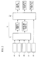
- Fig. 2 is a block diagram for explaining a method of distributing power in a control unit in Fig. 1.
- Fig. 3 is a diagram for explaining a plurality of sets of table data stored in a power-distribution calculating unit in Fig. 2.
- Fig. 4 is a block diagram for explaining a method of distributing power in a control unit of a forklift truck according to a second embodiment of the present invention.
- Fig. 5 is a diagram for explaining a plurality of sets of table data stored in a power-distribution calculating unit in Fig. 4.
- Fig. 6 is a block diagram for explaining a method of distributing power in a control unit of a forklift truck according to a third embodiment of the present invention.
- Fig. 7 which shows a plurality of sets of table data stored in a power-distribution calculating unit in Fig. 6, is a diagram for explaining one set of table data classified by battery voltage.
- Fig. 8 which shows a plurality of sets of table data stored in the power-distribution calculating unit in Fig. 6, is a diagram for explaining one set of table data classified by battery voltage.
- Fig. 9 which shows a plurality of sets of table data stored in the power-distribution calculating unit in Fig. 6, is a diagram for explaining one set of table data classified by battery voltage level.
- a forklift truck according to a first embodiment of the present invention will be described below with reference to Figs. 1 to 3.
- Fig. 1 is a diagram showing a power transmission system of a forklift truck 1 according to this embodiment.
- the forklift truck (industrial vehicle) 1 is provided with a running unit 3 for running; a loading-and-unloading unit 5 for loading and unloading; an engine 7 and a first motor 9 for supplying power to either the running unit 3 or the loading-and-unloading unit 5; a second motor 11 for supplying power to the running unit 3; and a control unit 13 that obtains required power for the running unit 3 and the loading-and-unloading unit 5 and controls a power distribution of the engine 7, the first motor 9, and the second motor 11.
- the running unit 3 is provided with a torque converter 15 for converting a torque of the power transmitted from a first-gear train 25 to a predetermined value; an FNR clutch (clutch unit) 17 for controlling the power transmission from the torque converter 15 to a second-gear train 19; the second-gear train 19 for transmitting the power from the FNR clutch 17 and the power of the second motor 11 to a differential device 21; the differential device 21 for transmitting the power to front wheels 23; and the front wheels 23 for running the forklift truck 1 by the power transmitted.
- a torque converter 15 for converting a torque of the power transmitted from a first-gear train 25 to a predetermined value
- an FNR clutch (clutch unit) 17 for controlling the power transmission from the torque converter 15 to a second-gear train 19
- the second-gear train 19 for transmitting the power from the FNR clutch 17 and the power of the second motor 11 to a differential device 21
- the differential device 21 for transmitting the power to front wheels 23
- the front wheels 23 for
- the FNR clutch 17 controls whether the forklift truck 1 is to move forward (F) without changing the rotational direction of the power or in reverse (R) by reversing the rotational direction, or whether the power transmission is to be blocked (neutral (N)).
- the FNR clutch 17 is controlled by an operator of the forklift truck 1 operating a clutch pedal (not shown in the drawing). The status of the FNR clutch 17 is input to a power-distribution calculating unit 43.
- the differential device 21 which is a device including a differential gear and so forth, changes the rotational direction of the power transmitted from the second-gear train 19, and absorbs any rotational difference between the right and left front wheels 23.
- the loading-and-unloading unit 5 is provided with a first-gear train 25 for transmitting the power of the engine 7 and the first motor 9 to the torque converter 15, a hydraulic motor 27, and a hydraulic pump 29; the hydraulic motor 27 and the hydraulic pump 29 for generating a hydraulic pressure by the power transmitted; a one-way clutch 31L for transmitting the power from the first-gear train 25 only to the hydraulic motor 27; and a fork 33 used for loading and unloading.
- the hydraulic motor 27 and the hydraulic pump 29 drive a hydraulic cylinder (not shown in the drawing) by the generated hydraulic pressure to raise and lower the fork 33.
- the one-way clutch 31R transmits the power from the engine 7 only to the first-gear train 25.
- the first motor 9 is connected to the first-gear train 25 by an output shaft thereof, and an electrical current is supplied from a battery 37 via a first inverter 35.
- the first inverter 35 converts DC current supplied from the battery 37 to AC current and controls the power generated by the first motor 9.
- a first-motor power command for controlling the power which the first motor 9 supplies is input to the first inverter 35 from the power-distribution calculating unit 43.
- the second motor 11 is connected to the second-gear train 19 by an output shaft thereof, and an electrical current is supplied from the battery 37 via a second inverter 39.
- the second inverter 39 converts DC current supplied from the battery 37 to AC current and controls the power generated by the second motor 11.
- a second-motor power command for controlling the power which the second motor 11 supplies is input to the second inverter 39 from the power-distribution calculating unit 43.
- the control unit 13 includes a required-power calculating unit 41 and the power-distribution calculating unit 43.
- the required-power calculating unit 41 calculates a running power (power for running) PR supplied to the running unit 3 and a loading-and-unloading power (power for loading and unloading) PL supplied to the loading-and-unloading unit 5.
- the power-distribution calculating unit 43 calculates the distribution of engine power PEG, first-motor power PM1, and second-motor power PM2.
- the power-distribution calculating unit 43 outputs the engine power command that is input to the engine 7, the first-motor power command that is input to the first motor 9, and the second-motor power command that is input to the second motor 11, based on the calculated power distribution.
- Fig. 2 is a block diagram for explaining a method of distributing power in a control unit 13 in Fig. 1.
- an accelerator-pedal depression amount 45, a brake-pedal depression amount 47, a lift-lever operating amount 49, and a tilt-lever operating amount 51 are input to the required-power calculating unit 41 of the control unit 13.
- the required-power calculating unit 41 calculates the running power PR required for running and the loading-and-unloading power PL required for loading and unloading based on these operating amounts that are input thereto (required-power calculating step).
- the running power PR required for running is obtained from the accelerator-pedal depression amount 45, the brake-pedal depression amount 47, and so forth; and the loading-and-unloading power PL required for loading and unloading is obtained from the lift-lever operating amount 49, the tilt-lever operating amount 51, and so forth.
- the calculated running power PR and loading-and-unloading power PL are input to the power-distribution calculating unit 43, and a clutch-pedal switch signal 53 showing the status of the FNR clutch 17 is further input thereto.
- the power-distribution calculating unit 43 selects one set of table data from a plurality of sets of table data that are stored in advance based on the clutch-pedal switch signal 53 and, based on the calculated running power PR and loading-and-unloading power PL, calculates the distribution of the engine power PEG, the first-motor power PM1, and the second-motor power PM2 to satisfy equation (1) below (power-distribution calculating step).
- P R + P L P EG + P M ⁇ 1 + P M ⁇ 2
- Equation (1) can also be represented by equation (2) below.
- P R + P L T EG ⁇ ⁇ EG + T M ⁇ 1 ⁇ ⁇ M ⁇ 1 + T M ⁇ 2 ⁇ ⁇ M ⁇ 2
- TEG is the engine torque
- ⁇ EG is the engine rotational speed
- TM1 is the first-motor torque
- ⁇ M1 is the first-motor rotation speed
- TM2 is the second-motor torque
- ⁇ M2 is the second-motor rotation speed.
- the power balance is satisfied by controlling three variables, that is, the engine power PEG, the first-motor power PM1, and the second-motor power PM2 in this embodiment.
- Fig. 3 is a diagram for explaining a plurality of sets of table data stored in the power-distribution calculating unit 43 in Fig. 2.
- the plurality of sets of table data stored in the power-distribution calculating unit 43 are classified by the clutch-pedal switch signal 53 (F: forward, N: neutral, and R: reverse).
- the power-distribution calculating unit 43 selects the table data corresponding to F, the table data corresponding to N, and the table data corresponding to R, respectively, based on the clutch-pedal switch signal 53.
- the power-distribution calculating unit 43 calculates the distribution of the engine power PEG, the first-motor power PM1, and the second-motor power PM2 based on the selected table data.
- the engine power PEG, the first-motor power PM1, and the second-motor power PM2 are all calculated based on the running power PR.
- the running power PR is from zero to the first predetermined power P1
- the power is distributed so that only the second-motor power PM2 is supplied to the running unit 3 in proportion to the running power PR; and when the running power PR is from the first predetermined power P1 to the second predetermined power P2, the power is distributed so that the first-motor power PM1 and the second-motor power PM2 are supplied to the running unit 3 in proportion to the running power PR.
- the power is distributed so that the first-motor power PM1 and the second-motor power PM2 are constantly supplied, and, at the same time, the engine power PEG is supplied to the running unit 3 in proportion to the running power PR; and when the running power PR is larger than the third predetermined power P3, the power is distributed so that the engine power PEG, the first-motor power PM1, and the second-motor power PM2 are constantly supplied to the running unit 3.
- the power distribution of the first-motor power PM1 and the second-motor power PM2 is the same as the above.
- the running power PR when the running power PR is from zero to a negative first predetermined power -P1, the power is distributed so that only the second-motor power PM2 is supplied to the running unit 3 in proportion to the running power PR; and when the running power PR is from the negative first predetermined power -P1 to a negative second predetermined power -P2, the power is distributed so that the first-motor power PM1 and the second-motor power PM2 are supplied to the running unit 3 in proportion to the running power PR.
- the running power PR is from the negative second predetermined power -P2 to a negative third predetermined power -P3
- the power is distributed so that the first-motor power PM1 and the second-motor power PM2 are constantly supplied.
- the engine power PEG and the first-motor power PM1 are calculated based on the loading-and-unloading power PL, and the second-motor power PM2 is calculated based on the running power PR.
- the power is distributed so that only the first-motor power PM1 is supplied to the loading-and-unloading unit 5 in proportion to the loading-and-unloading power PL; and when the loading-and-unloading power PL is from the fourth predetermined power P4 to a fifth predetermined power P5, the power is distributed so that the first-motor power PM1 is constantly supplied, and, at the same time, the engine power PEG is supplied to the loading-and-unloading unit 5 in proportion to the loading-and-unloading power PL.
- the loading-and-unloading power PL is larger than the fifth predetermined power P5, the power is distributed so that the engine power PEG and the first-motor power PM1 are constantly supplied to the loading-and-unloading unit 5.
- the running power PR is from zero to the fourth predetermined power P4, the power is distributed so that the second-motor power PM2 is supplied to the running unit 3 in proportion to the running power PR; and when the running power PR is larger than the fourth predetermined power P4, the power is distributed so that a constant power is supplied to the running unit 3.
- the power-distribution calculating unit 43 outputs the engine power command, the first-motor power command, and the second-motor power command to the engine 7, the first inverter 35, and the second inverter 39, respectively, based on the calculated engine power PEG, the first-motor power PM1, and the second-motor power PM2 described above.
- the table data where the distribution of the engine power PEG, the first-motor power PM1, and the second-motor power PM2 is defined, is not limited; the power may be distributed as shown in Fig. 3, or any other method of distributing power may be employed.
- the second-motor power command is input to the second inverter 39 to generate the second-motor power PM2 from the second motor 11.
- the second-motor power PM2 is input to the differential device 21 via the second-gear train 19.
- the second-motor power PM2 input to the differential device 21 is transmitted to the front wheels 23 to produce forward driving power of the forklift truck 1.
- the second-motor power PM2 is transmitted from the FNR clutch 17 to the first-gear train 25 via the torque converter 15; however, the power to the engine 7 is blocked by the one-way clutch 31R.
- the first-motor power command is further input to the first inverter 35 to generate the first-motor power PM1 from the first motor 9.
- the first-motor power PM1 is transmitted from the first-gear train 25 to the torque converter 15, the FNR clutch 17, the differential device 21, and the front wheels 23 in this order.
- the engine power command is further input to the engine 7 to generate the engine power PEG from the engine 7.
- the engine power PEG is transmitted from the one-way clutch 31R to the first-gear train 25, the torque converter 15, the FNR clutch 17, the differential device 21, and the front wheels 23 in this order.
- the FNR clutch 17 selection is N (neutral)
- the loading-and-unloading power PL is smaller than the fourth predetermined power P4
- the first-motor power command is input to the first inverter 35 to generate the first-motor power PM1 from the first motor 9.
- the first-motor power PM1 is transmitted from the first-gear train 25 to the hydraulic motor 27 and the hydraulic pump 29 to generate a hydraulic pressure at the hydraulic motor 27 and the hydraulic pump 29.
- the hydraulic cylinder (not shown in the drawing) is driven by the generated hydraulic pressure, and the fork 33 is raised and lowered accordingly.
- the engine power command is further input to the engine 7 to generate the engine power PEG from the engine 7.
- the engine power PEG is transmitted from the one-way clutch 31R to the first-gear train 25, the hydraulic motor 27, and the hydraulic pump 29 in this order.
- first-motor power PM1 and the engine power PEG are transmitted from the first-gear train 25 to the torque converter 15, they are blocked at the FNR clutch 17.
- the second-motor power command is input to the second inverter 39 to generate the second-motor power PM2 from the second motor 11.
- the second-motor power PM2 is input to the differential device 21 via the second-gear train 19.
- the second-motor power PM2 input to the differential device 21 is transmitted to the front wheels 23 to produce the forward propulsion of the forklift truck 1.
- the rotation produced at the loading and unloading device side is transmitted to the first motor 9 to drive the first motor 9, thus functioning as a generator which generates electrical power.
- the generated electrical power is stored at the battery 37 via the first inverter 35.
- the power-distribution calculating unit 43 calculates the distribution of these three variables, that is, the engine power PEG, the first-motor power PM1, and the second-motor power PM2, so as to satisfy the total of the running power PR and the loading-and-unloading power PL, the number of variables can be reduced compared to a distribution method based on torque distribution using many variables. Accordingly, the distribution control can be simplified.
- the destination to be supplied with engine power PEG and the first-motor power PM1 is selected as either the running unit 3 or the loading-and-unloading unit 5 based on the control status of the FNR clutch 17, thus further simplifying the power distribution control.
- the power distribution of the engine power PEG, the first-motor power PM1, and the second-motor power PM2 is determined according to the required running power PR and loading-and-unloading power PL, the power distribution can be determined so as to obtain the same operability as industrial vehicles used, for example, in loading and unloading operations, which have only an engine or a motor as a power source.
- the power can be used without waste, thus improving the fuel efficiency of the engine 7 and reducing the battery 37 consumption.
- the table data for setting the power distribution is stored in advance in the power-distribution calculating unit 43, it is possible to reduce the computational load for the power distribution, thus allowing a reduction in the computational time.
- the FNR clutch 17 transmits the power to the running unit 3 (in the case of F or R), the engine power PEG and the first-motor power PM1 are transmitted to the running unit 3; and when the FNR clutch 17 blocks the transmission power to the running unit 3 (in a case of N), the engine power PEG and the first-motor power PM1 are transmitted to the loading-and-unloading unit 5, and the power is thus used without waste.
- the basic configuration of the forklift truck of this embodiment is the same as that of the first embodiment, but the method of calculating the power distribution is different from that of the first embodiment. Therefore, only the method of calculating the power distribution will be described in this embodiment using Figs. 4 and 5, and a description of other elements will be omitted.
- Fig. 4 is a block diagram for explaining a method of distributing power in a control unit 113 of a forklift truck 101 according to this embodiment.
- the accelerator-pedal depression amount 45, the brake-pedal depression amount 47, the lift-lever operating amount 49, and the tilt-lever operating amount 51 are input to the required-power calculating unit 41 of the control unit 113 of the forklift truck (industrial vehicle) 101.
- the required-power calculating unit 41 calculates the running power PR required for running and the loading-and-unloading power PL required for loading and unloading based on these operating amounts that are input thereto.
- the calculated running power PR and loading-and-unloading power PL are input to a power-distribution calculating unit 143.
- the clutch-pedal switch signal 53 showing the status of the FNR clutch 17 and a running velocity V of the forklift truck 101, which is detected from a rotation speed of the second motor (velocity detection unit) 11 (see Fig. 1) are further input to the power-distribution calculating unit 143.
- the configuration is not particularly limited, however.
- the running velocity may be detected from the rotation speed of the second motor 11 connected to the front wheels 23 via the differential device 21 and the second-gear train 19, as described above, or a velocity sensor for detecting the running velocity of the forklift truck 101 may be separately provided.
- the power-distribution calculating unit 143 selects one set of table data from a plurality of sets of table data that are stored in advance based on the clutch-pedal switch signal 53 and, based on the calculated running power PR, loading-and-unloading power PL, and running velocity V, calculates the distribution of the engine power PEG, the first-motor power PM1, and the second-motor power PM2 to satisfy equation (1) above.
- Fig. 5 is a diagram for explaining a plurality of sets of table data stored in the power-distribution calculating unit 143 in Fig. 4.
- the plurality of sets of table data stored in the power-distribution calculating unit 143 are classified according to the clutch-pedal switch signal 53 (F: forward, N: neutral, and R: reverse).
- the power-distribution calculating unit 143 selects the table data corresponding to F, the table data corresponding to N, and the table data corresponding to R, respectively, based on the clutch-pedal switch signal 53.
- Each set of table data in which the distribution of the engine power PEG, the first-motor power PM1, and the second-motor power PM2 corresponding to the running power PR, the loading-and-unloading power PL, and the running velocity V input is defined, satisfies equation (1) above.
- the power-distribution calculating unit 143 calculates the distribution of the engine power PEG, the first-motor power PM1, and the second-motor power PM2 based on the selected table data and changes the power distribution according to the value of the running velocity V when the clutch-pedal switch signal 53 is F or R.
- the description is applied to a case where the power distribution is the same as that of the first embodiment when the value of the running velocity V is zero. Therefore, the description of when the value of the running velocity V is zero will be omitted.
- the power distribution ratio of the engine power PEG increases according to the increase of the running velocity V.
- the power distribution ratio of the first-motor power PM1 decreases according to the increase of the running velocity V value when the required power (PR) is positive, and increases according to the increase of the running velocity V value when the required power (PR) is negative.
- the power distribution ratio of the second-motor power PM2 decreases according to the increase of the running velocity V value when the required power (PL) is positive, and increases according to the running velocity V value when the required power (PL) is negative.
- the power distribution ratio increases according to the increase of the running velocity V value when the required power (PR) is positive, and decreases according to the running velocity V value when the required power (PR) is negative.
- the basic configuration of the forklift truck of this embodiment is the same as that of the first embodiment, but the method of calculating a power distribution is different from the first embodiment. Therefore, only the method of calculating the power distribution will be described in this embodiment using Figs. 6 to 9, and a description of other elements will be omitted.
- Fig. 6 is a block diagram for explaining a method of distributing power in a control unit 213 of a forklift truck 201 according to this embodiment.
- the accelerator-pedal depression amount 45, the brake-pedal depression amount 47, the lift-lever operating amount 49, and the tilt-lever operating amount 51 are input to the required-power calculating unit 41 of the control unit 213 of the forklift truck (industrial vehicle) 201.
- the required-power calculating unit 41 calculates the running power PR required for running and the loading-and-unloading power PL required for loading and unloading based on these operating amounts that are input thereto.
- the calculated running power PR and the loading-and-unloading power PL are input to a power-distribution calculating unit 243, and the clutch-pedal switch signal 53 showing the status of the FNR clutch 17 and the running velocity V of the forklift truck 201 detected from the rotation speed of the second motor 11 (see Fig. 1) are further input to the power-distribution calculating unit 243.
- the power-distribution calculating unit 243 also serves as a voltage detection unit.
- the configuration is not particularly limited, however.
- the power-distribution calculating unit 243 may directly detect a battery voltage Eb as described above, or a voltage detection sensor for detecting the battery voltage Eb may be separately provided.
- the power-distribution calculating unit 243 selects one set of table data from a plurality of sets of table data that are stored in advance based on the clutch-pedal switch signal 53 and, based on the calculated running power PR and loading-and-unloading power PL, as well as the running velocity V and the battery voltage Eb, calculates the distribution of the engine power PEG, the first-motor power PM1, and the second-motor power PM2 to satisfy equation (1) above.
- Figs. 7 to 9 which show a plurality of sets of table data stored in the power-distribution calculating unit 243 shown in Fig. 6, are diagrams for explaining one set of table data classified by battery voltage.
- the plurality of sets of table data stored in the power-distribution calculating unit 243 are classified by battery voltage Eb: from a first predetermined voltage E1 to a second predetermined voltage E2 or less (Fig. 7), from the second predetermined voltage E2 to a third predetermined voltage E3 or less (Fig. 8), or from the third predetermined voltage E3 to a fourth predetermined voltage E4 or less (Fig. 9). It is further classified by clutch-pedal switch signal 53 (F: forward, N: neutral, and R: reverse) (Figs. 7 to 9).
- the power-distribution calculating unit 243 selects table data based on the value of the battery voltage Eb, and further selects the table data corresponding to F, the table data corresponding to N, and the table data corresponding to R, respectively, based on the clutch-pedal switch signal 53.
- Each set of table data in which the distribution of the engine power PEG, the first-motor power PM1, and the second-motor power PM2 corresponding to the running power PR, the loading-and-unloading power PL, and the running velocity V input is defined, satisfies equation (1) above.
- the power-distribution calculating unit 243 selects the table data shown in Fig. 7. In this table data, the method of distributing the engine power PEG is different from that of the first and second embodiments.
- the power when the table data corresponding to F or R is selected, and when the running power PR is from zero to the second predetermined power P2, the power is distributed so that the engine power PEG is supplied to the running unit 3 in proportion to the running power PR, and when the running power PR is higher than the second predetermined power P2, the power is distributed so that the engine power PEG is constantly supplied.
- the power is distributed so that the engine power PEG is supplied to the loading-and-unloading unit 5 in proportion to the loading-and-unloading power PL; and when the loading-and-unloading power PL is higher than the fifth predetermined power P5b, the power is distributed so that the engine power PEG is constantly supplied.
- the power-distribution calculating unit 243 selects the table data shown in Fig. 8.
- the engine power PEG is not supplied when the running power PR is from zero to the first predetermined power P1.
- the running power PR is from the first predetermined power P1 to the second predetermined power P2, the power is distributed so that the engine power PEG is supplied to the running unit 3 in proportion to the running power PR, and when the running power PR is higher than the second predetermined power P2, the power is distributed so that the engine power PEG is constantly supplied.
- the engine power PEG is not supplied when the loading-and-unloading power PL is from zero to a fourth predetermined power P4a.
- the loading-and-unloading power PL is from the fourth predetermined power P4a to a fifth predetermined power P5a, the power is distributed so that the engine power PEG is supplied to the loading-and-unloading unit 5 in proportion to the loading-and-unloading power PL; and when the loading-and-unloading power PL is higher than the fifth predetermined power P5a, the power is distributed so that the engine power PEG is constantly supplied.
- the power-distribution calculating unit 243 selects the table data shown in Fig. 9.
- the table data shown in Fig. 9 is similar to the table data described in the second embodiment, and a description thereof will be omitted.
- the power-distribution calculating unit 243 calculates the distribution of the engine power PEG, the first-motor power PM1, and the second-motor power PM2 based on the selected table data.
- the table data shown in Figs. 7 to 9 is used to change the power distribution according to the value of the running velocity V when the clutch-pedal switch signal 53 is F or R.
- the specific power distribution is the same as that of the second embodiment, and the description thereof will be omitted.
Landscapes
- Engineering & Computer Science (AREA)
- Transportation (AREA)
- Mechanical Engineering (AREA)
- Chemical & Material Sciences (AREA)
- Combustion & Propulsion (AREA)
- Power Engineering (AREA)
- Life Sciences & Earth Sciences (AREA)
- Structural Engineering (AREA)
- Sustainable Energy (AREA)
- Civil Engineering (AREA)
- Sustainable Development (AREA)
- Geology (AREA)
- Automation & Control Theory (AREA)
- Hybrid Electric Vehicles (AREA)
- Electric Propulsion And Braking For Vehicles (AREA)
- Control Of Vehicle Engines Or Engines For Specific Uses (AREA)
- Forklifts And Lifting Vehicles (AREA)
Applications Claiming Priority (1)
| Application Number | Priority Date | Filing Date | Title |
|---|---|---|---|
| JP2006303781A JP4072183B1 (ja) | 2006-11-09 | 2006-11-09 | 作業車両および作業車両の動力制御方法 |
Publications (3)
| Publication Number | Publication Date |
|---|---|
| EP1920987A2 true EP1920987A2 (de) | 2008-05-14 |
| EP1920987A3 EP1920987A3 (de) | 2009-12-02 |
| EP1920987B1 EP1920987B1 (de) | 2013-05-22 |
Family
ID=38828543
Family Applications (1)
| Application Number | Title | Priority Date | Filing Date |
|---|---|---|---|
| EP07120014.1A Active EP1920987B1 (de) | 2006-11-09 | 2007-11-05 | Nutzfahrzeug und Leistungssteuerungsverfahren dafür |
Country Status (4)
| Country | Link |
|---|---|
| US (1) | US8165738B2 (de) |
| EP (1) | EP1920987B1 (de) |
| JP (1) | JP4072183B1 (de) |
| KR (1) | KR20080042697A (de) |
Cited By (1)
| Publication number | Priority date | Publication date | Assignee | Title |
|---|---|---|---|---|
| EP2703242A4 (de) * | 2011-04-28 | 2015-12-23 | Mitsubishi Nichiyu Forklift Co | Hybridnutzfahrzeug |
Families Citing this family (17)
| Publication number | Priority date | Publication date | Assignee | Title |
|---|---|---|---|---|
| JP4100440B2 (ja) * | 2006-09-26 | 2008-06-11 | トヨタ自動車株式会社 | ハイブリッド車両の制御装置 |
| US8098054B2 (en) * | 2007-10-10 | 2012-01-17 | John Alexander Verschuur | Optimal load controller method and device |
| CA2709279C (en) * | 2007-12-12 | 2014-04-15 | Foss Maritime Company | Hybrid propulsion systems |
| JP5314906B2 (ja) | 2008-02-29 | 2013-10-16 | ニチユ三菱フォークリフト株式会社 | 作業用車両の制御方法および作業用車両 |
| KR100911596B1 (ko) * | 2009-03-31 | 2009-08-07 | 하청수 | 이원 동력 전달 시스템의 작업차량 |
| CN102666169A (zh) * | 2010-01-18 | 2012-09-12 | 日立建机株式会社 | 作业用车辆的驱动控制装置 |
| FR2971742B1 (fr) * | 2011-02-22 | 2013-02-22 | Richard Chene | Vehicule automobile a trois moteurs electrique, hydraulique et thermique et procede de gestion des energies stockees a bord |
| JP2013048608A (ja) * | 2011-08-31 | 2013-03-14 | Kokusan Denki Co Ltd | 電動式作業車両 |
| CN102501760B (zh) * | 2011-11-09 | 2014-09-17 | 中国人民解放军军事交通学院 | 蓄电池叉车电动机驱动切换系统 |
| JP2014133455A (ja) * | 2013-01-09 | 2014-07-24 | Hitachi Constr Mach Co Ltd | 建設機械の油圧ポンプ駆動装置 |
| CN103407935A (zh) * | 2013-08-12 | 2013-11-27 | 山西天脊山电动车船有限公司 | 单电机全功能叉车 |
| US9873601B2 (en) * | 2013-11-06 | 2018-01-23 | Clark Material Handling Company | Hybrid forklift truck |
| CN105468930B (zh) * | 2015-12-30 | 2018-08-31 | 安徽江淮银联重型工程机械有限公司 | 一种基于动力因数方程组的叉车发动机额定功率计算方法 |
| US10808641B2 (en) * | 2018-10-29 | 2020-10-20 | Caterpillar Inc. | Mobile machines, electric drive systems, and methods for testing electric drive systems |
| JP7417401B2 (ja) * | 2019-11-01 | 2024-01-18 | 株式会社エクセディ | 駆動システム |
| DE202020101432U1 (de) | 2020-03-16 | 2021-06-17 | Liebherr-Mischtechnik Gmbh | Autobetonpumpe |
| JP7619249B2 (ja) * | 2021-12-03 | 2025-01-22 | 株式会社豊田自動織機 | 産業車両 |
Citations (1)
| Publication number | Priority date | Publication date | Assignee | Title |
|---|---|---|---|---|
| EP1707418A2 (de) | 2005-03-29 | 2006-10-04 | Kabushiki Kaisha Toyota Jidoshokki | Hybrid-angetriebenen Gabelstapler |
Family Cites Families (27)
| Publication number | Priority date | Publication date | Assignee | Title |
|---|---|---|---|---|
| DE4317782C2 (de) * | 1993-05-28 | 1996-01-18 | Jungheinrich Ag | Hydraulische Hubvorrichtung für batteriegetriebene Flurförderzeuge oder dergleichen |
| JP3775012B2 (ja) * | 1997-08-29 | 2006-05-17 | アイシン・エィ・ダブリュ株式会社 | 車両用ハイブリッド駆動装置 |
| DE19747459C2 (de) | 1997-10-27 | 2003-02-06 | Brueninghaus Hydromatik Gmbh | Hydrostatisch-mechanischer Fahrantrieb |
| JP3692828B2 (ja) | 1999-04-28 | 2005-09-07 | 株式会社豊田自動織機 | 荷役作業用産業車両 |
| DE19930793B4 (de) | 1999-07-03 | 2004-03-25 | Rofan Gmbh | Hybridantrieb |
| DE19955311C2 (de) * | 1999-11-17 | 2003-12-24 | Jungheinrich Ag | Antriebssystem für ein Flurförderzeug |
| DE19955313C2 (de) * | 1999-11-17 | 2003-12-18 | Jungheinrich Ag | Antriebssystem für Flurförderzeuge |
| JP2001316096A (ja) * | 2000-02-28 | 2001-11-13 | Toyota Industries Corp | 産業車両の油圧装置 |
| JP3569210B2 (ja) * | 2000-08-11 | 2004-09-22 | 本田技研工業株式会社 | ハイブリッド車両の動力伝達装置及びその制御方法 |
| JP3593983B2 (ja) * | 2001-01-16 | 2004-11-24 | 日産自動車株式会社 | 車両の駆動力制御装置 |
| JP2002315105A (ja) * | 2001-04-12 | 2002-10-25 | Komatsu Ltd | ホイールローダ |
| EP1270301A3 (de) * | 2001-06-19 | 2007-02-21 | Hitachi, Ltd. | Kraftfahrzeuggetriebe mit Schaltungen ohne Drehmoment Unterbrechung |
| JP3714914B2 (ja) | 2002-02-22 | 2005-11-09 | Tcm株式会社 | 荷役機能を有する走行車両 |
| JP4411827B2 (ja) * | 2002-07-31 | 2010-02-10 | アイシン精機株式会社 | ハイブリッド車両用動力伝達装置 |
| JP4179465B2 (ja) * | 2002-07-31 | 2008-11-12 | 株式会社小松製作所 | 建設機械 |
| JP4047110B2 (ja) * | 2002-09-11 | 2008-02-13 | 株式会社小松製作所 | 建設機械 |
| US6962545B2 (en) * | 2002-09-23 | 2005-11-08 | Bae Systems Onctrols | Multi-range parallel-hybrid continuously variable transmission |
| DE10244769A1 (de) * | 2002-09-26 | 2004-04-08 | Still Gmbh | Mobile Arbeitsmaschine |
| JP4031770B2 (ja) | 2004-04-06 | 2008-01-09 | トヨタ自動車株式会社 | 動力出力装置およびこれを搭載する自動車 |
| TWI330218B (en) * | 2004-10-29 | 2010-09-11 | Tai Her Yang | Split serial-parallel hybrid dual-power drive system |
| EP1852387B1 (de) * | 2005-02-25 | 2013-04-03 | Mitsubishi Heavy Industries, Ltd. | Lasthandhabungsregenerationsverfahren und lasthandhabungsregenerationssystem für batteriebetriebenes industriefahrzeug |
| JP4792780B2 (ja) | 2005-03-29 | 2011-10-12 | 株式会社豊田自動織機 | ハイブリッド型フォークリフト |
| JP2006273517A (ja) | 2005-03-29 | 2006-10-12 | Toyota Industries Corp | ハイブリッド型フォークリフト |
| JP2006273513A (ja) | 2005-03-29 | 2006-10-12 | Toyota Industries Corp | ハイブリッド型フォークリフト |
| JP2006273516A (ja) | 2005-03-29 | 2006-10-12 | Toyota Industries Corp | ハイブリッド型フォークリフト |
| US7950481B2 (en) * | 2005-09-29 | 2011-05-31 | Caterpillar Inc. | Electric powertrain for machine |
| US20070095587A1 (en) * | 2005-11-03 | 2007-05-03 | Hybrid Dynamics Corp. | Hybrid vehicle drive train and method |
-
2006
- 2006-11-09 JP JP2006303781A patent/JP4072183B1/ja not_active Expired - Fee Related
-
2007
- 2007-10-29 US US11/976,903 patent/US8165738B2/en active Active
- 2007-11-05 EP EP07120014.1A patent/EP1920987B1/de active Active
- 2007-11-06 KR KR1020070112794A patent/KR20080042697A/ko not_active Ceased
Patent Citations (1)
| Publication number | Priority date | Publication date | Assignee | Title |
|---|---|---|---|---|
| EP1707418A2 (de) | 2005-03-29 | 2006-10-04 | Kabushiki Kaisha Toyota Jidoshokki | Hybrid-angetriebenen Gabelstapler |
Cited By (2)
| Publication number | Priority date | Publication date | Assignee | Title |
|---|---|---|---|---|
| EP2703242A4 (de) * | 2011-04-28 | 2015-12-23 | Mitsubishi Nichiyu Forklift Co | Hybridnutzfahrzeug |
| US9312685B2 (en) | 2011-04-28 | 2016-04-12 | Mitsubishi Nichiyu Forklift Co., Ltd. | Hybrid industrial vehicle |
Also Published As
| Publication number | Publication date |
|---|---|
| JP4072183B1 (ja) | 2008-04-09 |
| EP1920987A3 (de) | 2009-12-02 |
| KR20080042697A (ko) | 2008-05-15 |
| JP2008120158A (ja) | 2008-05-29 |
| US20080133077A1 (en) | 2008-06-05 |
| EP1920987B1 (de) | 2013-05-22 |
| US8165738B2 (en) | 2012-04-24 |
Similar Documents
| Publication | Publication Date | Title |
|---|---|---|
| EP1920987B1 (de) | Nutzfahrzeug und Leistungssteuerungsverfahren dafür | |
| KR102018474B1 (ko) | 하이브리드 자동차의 구동 장치 제어 방법, 그리고 하이브리드 자동차 | |
| US8146691B2 (en) | Travel drive system for work vehicle, work vehicle, and travel drive method | |
| US9790663B2 (en) | Work vehicle having a work implement | |
| JP5356543B2 (ja) | 作業用車両の駆動制御装置 | |
| JP5095252B2 (ja) | 建設機械及びその制御方法 | |
| EP3053797B1 (de) | Nutzfahrzeug und nutzfahrzeugsteuerungsverfahren | |
| JPH11332009A (ja) | ハイブリッド車 | |
| CN102216137A (zh) | 并联式混合动力汽车上混合运行中的动力点移位方法 | |
| JP4764018B2 (ja) | 走行作業機械 | |
| JP2010540860A (ja) | 動力源回転数可変型cvt制御システム | |
| JP2011093345A (ja) | 車両系建設機械及びその制御方法 | |
| US9290169B2 (en) | Vehicle control apparatus | |
| JP5123024B2 (ja) | 走行作業車両 | |
| JP2015171205A (ja) | 車両の制御装置 | |
| JP2005269793A (ja) | ハイブリッド車両 | |
| JP4439310B2 (ja) | ハイブリッド車両 | |
| JP2005090667A (ja) | ハイブリッド車輌の変速制御装置 | |
| JP5128871B2 (ja) | ハイブリッド型荷役車両の荷役制御方法及び装置 | |
| RU2388643C2 (ru) | Рабочая машина и способ ее эксплуатации | |
| JP2000299904A (ja) | ハイブリッド車 | |
| JP2000156901A (ja) | 電気自動車の制御装置 | |
| JP2000156915A (ja) | ハイブリッド車の制御装置 | |
| JP2003309904A (ja) | 作業用車両の駆動制御装置 | |
| JP2008074336A (ja) | ハイブリッド車両の表示制御装置、表示制御方法、その表示制御方法をコンピュータで実現するプログラムおよびそのプログラムを記録した記録媒体 |
Legal Events
| Date | Code | Title | Description |
|---|---|---|---|
| PUAI | Public reference made under article 153(3) epc to a published international application that has entered the european phase |
Free format text: ORIGINAL CODE: 0009012 |
|
| AK | Designated contracting states |
Kind code of ref document: A2 Designated state(s): AT BE BG CH CY CZ DE DK EE ES FI FR GB GR HU IE IS IT LI LT LU LV MC MT NL PL PT RO SE SI SK TR |
|
| AX | Request for extension of the european patent |
Extension state: AL BA HR MK RS |
|
| PUAL | Search report despatched |
Free format text: ORIGINAL CODE: 0009013 |
|
| AK | Designated contracting states |
Kind code of ref document: A3 Designated state(s): AT BE BG CH CY CZ DE DK EE ES FI FR GB GR HU IE IS IT LI LT LU LV MC MT NL PL PT RO SE SI SK TR |
|
| AX | Request for extension of the european patent |
Extension state: AL BA HR MK RS |
|
| 17P | Request for examination filed |
Effective date: 20100602 |
|
| AKX | Designation fees paid |
Designated state(s): AT BE BG CH CY CZ DE DK EE ES FI FR GB GR HU IE IS IT LI LT LU LV MC MT NL PL PT RO SE SI SK TR |
|
| 17Q | First examination report despatched |
Effective date: 20110330 |
|
| RIC1 | Information provided on ipc code assigned before grant |
Ipc: B66F 9/20 20060101ALI20120914BHEP Ipc: B60W 20/00 20060101AFI20120914BHEP Ipc: B60W 10/30 20060101ALI20120914BHEP Ipc: B60W 10/08 20060101ALI20120914BHEP Ipc: B60K 6/38 20071001ALI20120914BHEP Ipc: B60K 6/48 20071001ALI20120914BHEP Ipc: B60W 10/02 20060101ALI20120914BHEP Ipc: B60W 10/06 20060101ALI20120914BHEP |
|
| GRAP | Despatch of communication of intention to grant a patent |
Free format text: ORIGINAL CODE: EPIDOSNIGR1 |
|
| GRAS | Grant fee paid |
Free format text: ORIGINAL CODE: EPIDOSNIGR3 |
|
| GRAA | (expected) grant |
Free format text: ORIGINAL CODE: 0009210 |
|
| AK | Designated contracting states |
Kind code of ref document: B1 Designated state(s): AT BE BG CH CY CZ DE DK EE ES FI FR GB GR HU IE IS IT LI LT LU LV MC MT NL PL PT RO SE SI SK TR |
|
| REG | Reference to a national code |
Ref country code: GB Ref legal event code: FG4D |
|
| REG | Reference to a national code |
Ref country code: CH Ref legal event code: EP |
|
| REG | Reference to a national code |
Ref country code: AT Ref legal event code: REF Ref document number: 613056 Country of ref document: AT Kind code of ref document: T Effective date: 20130615 |
|
| REG | Reference to a national code |
Ref country code: IE Ref legal event code: FG4D |
|
| REG | Reference to a national code |
Ref country code: DE Ref legal event code: R096 Ref document number: 602007030559 Country of ref document: DE Effective date: 20130718 |
|
| REG | Reference to a national code |
Ref country code: AT Ref legal event code: MK05 Ref document number: 613056 Country of ref document: AT Kind code of ref document: T Effective date: 20130522 |
|
| REG | Reference to a national code |
Ref country code: LT Ref legal event code: MG4D |
|
| PG25 | Lapsed in a contracting state [announced via postgrant information from national office to epo] |
Ref country code: SE Free format text: LAPSE BECAUSE OF FAILURE TO SUBMIT A TRANSLATION OF THE DESCRIPTION OR TO PAY THE FEE WITHIN THE PRESCRIBED TIME-LIMIT Effective date: 20130522 Ref country code: PT Free format text: LAPSE BECAUSE OF FAILURE TO SUBMIT A TRANSLATION OF THE DESCRIPTION OR TO PAY THE FEE WITHIN THE PRESCRIBED TIME-LIMIT Effective date: 20130923 Ref country code: AT Free format text: LAPSE BECAUSE OF FAILURE TO SUBMIT A TRANSLATION OF THE DESCRIPTION OR TO PAY THE FEE WITHIN THE PRESCRIBED TIME-LIMIT Effective date: 20130522 Ref country code: ES Free format text: LAPSE BECAUSE OF FAILURE TO SUBMIT A TRANSLATION OF THE DESCRIPTION OR TO PAY THE FEE WITHIN THE PRESCRIBED TIME-LIMIT Effective date: 20130902 Ref country code: SI Free format text: LAPSE BECAUSE OF FAILURE TO SUBMIT A TRANSLATION OF THE DESCRIPTION OR TO PAY THE FEE WITHIN THE PRESCRIBED TIME-LIMIT Effective date: 20130522 Ref country code: IS Free format text: LAPSE BECAUSE OF FAILURE TO SUBMIT A TRANSLATION OF THE DESCRIPTION OR TO PAY THE FEE WITHIN THE PRESCRIBED TIME-LIMIT Effective date: 20130922 Ref country code: LT Free format text: LAPSE BECAUSE OF FAILURE TO SUBMIT A TRANSLATION OF THE DESCRIPTION OR TO PAY THE FEE WITHIN THE PRESCRIBED TIME-LIMIT Effective date: 20130522 Ref country code: FI Free format text: LAPSE BECAUSE OF FAILURE TO SUBMIT A TRANSLATION OF THE DESCRIPTION OR TO PAY THE FEE WITHIN THE PRESCRIBED TIME-LIMIT Effective date: 20130522 Ref country code: GR Free format text: LAPSE BECAUSE OF FAILURE TO SUBMIT A TRANSLATION OF THE DESCRIPTION OR TO PAY THE FEE WITHIN THE PRESCRIBED TIME-LIMIT Effective date: 20130823 |
|
| REG | Reference to a national code |
Ref country code: NL Ref legal event code: VDEP Effective date: 20130522 |
|
| RAP2 | Party data changed (patent owner data changed or rights of a patent transferred) |
Owner name: MITSUBISHI NICHIYU FORKLIFT CO., LTD. |
|
| PG25 | Lapsed in a contracting state [announced via postgrant information from national office to epo] |
Ref country code: PL Free format text: LAPSE BECAUSE OF FAILURE TO SUBMIT A TRANSLATION OF THE DESCRIPTION OR TO PAY THE FEE WITHIN THE PRESCRIBED TIME-LIMIT Effective date: 20130522 Ref country code: BG Free format text: LAPSE BECAUSE OF FAILURE TO SUBMIT A TRANSLATION OF THE DESCRIPTION OR TO PAY THE FEE WITHIN THE PRESCRIBED TIME-LIMIT Effective date: 20130822 |
|
| PG25 | Lapsed in a contracting state [announced via postgrant information from national office to epo] |
Ref country code: LV Free format text: LAPSE BECAUSE OF FAILURE TO SUBMIT A TRANSLATION OF THE DESCRIPTION OR TO PAY THE FEE WITHIN THE PRESCRIBED TIME-LIMIT Effective date: 20130522 |
|
| PG25 | Lapsed in a contracting state [announced via postgrant information from national office to epo] |
Ref country code: BE Free format text: LAPSE BECAUSE OF FAILURE TO SUBMIT A TRANSLATION OF THE DESCRIPTION OR TO PAY THE FEE WITHIN THE PRESCRIBED TIME-LIMIT Effective date: 20130522 Ref country code: EE Free format text: LAPSE BECAUSE OF FAILURE TO SUBMIT A TRANSLATION OF THE DESCRIPTION OR TO PAY THE FEE WITHIN THE PRESCRIBED TIME-LIMIT Effective date: 20130522 Ref country code: CZ Free format text: LAPSE BECAUSE OF FAILURE TO SUBMIT A TRANSLATION OF THE DESCRIPTION OR TO PAY THE FEE WITHIN THE PRESCRIBED TIME-LIMIT Effective date: 20130522 Ref country code: SK Free format text: LAPSE BECAUSE OF FAILURE TO SUBMIT A TRANSLATION OF THE DESCRIPTION OR TO PAY THE FEE WITHIN THE PRESCRIBED TIME-LIMIT Effective date: 20130522 Ref country code: DK Free format text: LAPSE BECAUSE OF FAILURE TO SUBMIT A TRANSLATION OF THE DESCRIPTION OR TO PAY THE FEE WITHIN THE PRESCRIBED TIME-LIMIT Effective date: 20130522 |
|
| PG25 | Lapsed in a contracting state [announced via postgrant information from national office to epo] |
Ref country code: RO Free format text: LAPSE BECAUSE OF FAILURE TO SUBMIT A TRANSLATION OF THE DESCRIPTION OR TO PAY THE FEE WITHIN THE PRESCRIBED TIME-LIMIT Effective date: 20130522 Ref country code: NL Free format text: LAPSE BECAUSE OF FAILURE TO SUBMIT A TRANSLATION OF THE DESCRIPTION OR TO PAY THE FEE WITHIN THE PRESCRIBED TIME-LIMIT Effective date: 20130522 |
|
| PLBE | No opposition filed within time limit |
Free format text: ORIGINAL CODE: 0009261 |
|
| STAA | Information on the status of an ep patent application or granted ep patent |
Free format text: STATUS: NO OPPOSITION FILED WITHIN TIME LIMIT |
|
| 26N | No opposition filed |
Effective date: 20140225 |
|
| REG | Reference to a national code |
Ref country code: DE Ref legal event code: R097 Ref document number: 602007030559 Country of ref document: DE Effective date: 20140225 |
|
| REG | Reference to a national code |
Ref country code: CH Ref legal event code: PL |
|
| PG25 | Lapsed in a contracting state [announced via postgrant information from national office to epo] |
Ref country code: CH Free format text: LAPSE BECAUSE OF NON-PAYMENT OF DUE FEES Effective date: 20131130 Ref country code: LI Free format text: LAPSE BECAUSE OF NON-PAYMENT OF DUE FEES Effective date: 20131130 Ref country code: MC Free format text: LAPSE BECAUSE OF FAILURE TO SUBMIT A TRANSLATION OF THE DESCRIPTION OR TO PAY THE FEE WITHIN THE PRESCRIBED TIME-LIMIT Effective date: 20130522 |
|
| REG | Reference to a national code |
Ref country code: IE Ref legal event code: MM4A |
|
| PG25 | Lapsed in a contracting state [announced via postgrant information from national office to epo] |
Ref country code: IE Free format text: LAPSE BECAUSE OF NON-PAYMENT OF DUE FEES Effective date: 20131105 |
|
| PG25 | Lapsed in a contracting state [announced via postgrant information from national office to epo] |
Ref country code: CY Free format text: LAPSE BECAUSE OF FAILURE TO SUBMIT A TRANSLATION OF THE DESCRIPTION OR TO PAY THE FEE WITHIN THE PRESCRIBED TIME-LIMIT Effective date: 20130522 Ref country code: TR Free format text: LAPSE BECAUSE OF FAILURE TO SUBMIT A TRANSLATION OF THE DESCRIPTION OR TO PAY THE FEE WITHIN THE PRESCRIBED TIME-LIMIT Effective date: 20130522 |
|
| PG25 | Lapsed in a contracting state [announced via postgrant information from national office to epo] |
Ref country code: LU Free format text: LAPSE BECAUSE OF NON-PAYMENT OF DUE FEES Effective date: 20131105 Ref country code: HU Free format text: LAPSE BECAUSE OF FAILURE TO SUBMIT A TRANSLATION OF THE DESCRIPTION OR TO PAY THE FEE WITHIN THE PRESCRIBED TIME-LIMIT; INVALID AB INITIO Effective date: 20071105 |
|
| PG25 | Lapsed in a contracting state [announced via postgrant information from national office to epo] |
Ref country code: MT Free format text: LAPSE BECAUSE OF FAILURE TO SUBMIT A TRANSLATION OF THE DESCRIPTION OR TO PAY THE FEE WITHIN THE PRESCRIBED TIME-LIMIT Effective date: 20130522 |
|
| REG | Reference to a national code |
Ref country code: FR Ref legal event code: PLFP Year of fee payment: 9 |
|
| REG | Reference to a national code |
Ref country code: FR Ref legal event code: PLFP Year of fee payment: 10 |
|
| REG | Reference to a national code |
Ref country code: FR Ref legal event code: PLFP Year of fee payment: 11 |
|
| REG | Reference to a national code |
Ref country code: FR Ref legal event code: PLFP Year of fee payment: 12 |
|
| P01 | Opt-out of the competence of the unified patent court (upc) registered |
Effective date: 20230509 |
|
| PGFP | Annual fee paid to national office [announced via postgrant information from national office to epo] |
Ref country code: DE Payment date: 20241001 Year of fee payment: 18 |
|
| PGFP | Annual fee paid to national office [announced via postgrant information from national office to epo] |
Ref country code: GB Payment date: 20241002 Year of fee payment: 18 |
|
| PGFP | Annual fee paid to national office [announced via postgrant information from national office to epo] |
Ref country code: FR Payment date: 20241001 Year of fee payment: 18 |
|
| PGFP | Annual fee paid to national office [announced via postgrant information from national office to epo] |
Ref country code: IT Payment date: 20241010 Year of fee payment: 18 |