EP1920977B1 - Sicherheitsgurtvorrichtung für ein Fahrzeug - Google Patents
Sicherheitsgurtvorrichtung für ein Fahrzeug Download PDFInfo
- Publication number
- EP1920977B1 EP1920977B1 EP07021729A EP07021729A EP1920977B1 EP 1920977 B1 EP1920977 B1 EP 1920977B1 EP 07021729 A EP07021729 A EP 07021729A EP 07021729 A EP07021729 A EP 07021729A EP 1920977 B1 EP1920977 B1 EP 1920977B1
- Authority
- EP
- European Patent Office
- Prior art keywords
- seatbelt
- winding
- motor
- belt reel
- winding position
- Prior art date
- Legal status (The legal status is an assumption and is not a legal conclusion. Google has not performed a legal analysis and makes no representation as to the accuracy of the status listed.)
- Not-in-force
Links
- 238000004804 winding Methods 0.000 claims description 247
- 230000005611 electricity Effects 0.000 claims description 48
- 238000001514 detection method Methods 0.000 claims description 15
- 230000003247 decreasing effect Effects 0.000 claims description 12
- 230000007423 decrease Effects 0.000 claims description 11
- 238000000034 method Methods 0.000 description 87
- 230000008569 process Effects 0.000 description 87
- 238000005034 decoration Methods 0.000 description 7
- 230000008859 change Effects 0.000 description 6
- 238000010276 construction Methods 0.000 description 5
- 230000003213 activating effect Effects 0.000 description 2
- 230000004913 activation Effects 0.000 description 2
- 238000010586 diagram Methods 0.000 description 2
- 230000001133 acceleration Effects 0.000 description 1
- 238000007792 addition Methods 0.000 description 1
- 238000004891 communication Methods 0.000 description 1
- 230000000694 effects Effects 0.000 description 1
- 239000004744 fabric Substances 0.000 description 1
- 238000012886 linear function Methods 0.000 description 1
- 230000033001 locomotion Effects 0.000 description 1
- 238000012986 modification Methods 0.000 description 1
- 230000004048 modification Effects 0.000 description 1
- 238000011946 reduction process Methods 0.000 description 1
- 230000000087 stabilizing effect Effects 0.000 description 1
- 238000006467 substitution reaction Methods 0.000 description 1
Images



Classifications
-
- B—PERFORMING OPERATIONS; TRANSPORTING
- B60—VEHICLES IN GENERAL
- B60R—VEHICLES, VEHICLE FITTINGS, OR VEHICLE PARTS, NOT OTHERWISE PROVIDED FOR
- B60R22/00—Safety belts or body harnesses in vehicles
- B60R22/34—Belt retractors, e.g. reels
- B60R22/44—Belt retractors, e.g. reels with means for reducing belt tension during use under normal conditions
-
- B—PERFORMING OPERATIONS; TRANSPORTING
- B60—VEHICLES IN GENERAL
- B60R—VEHICLES, VEHICLE FITTINGS, OR VEHICLE PARTS, NOT OTHERWISE PROVIDED FOR
- B60R22/00—Safety belts or body harnesses in vehicles
- B60R22/34—Belt retractors, e.g. reels
- B60R22/44—Belt retractors, e.g. reels with means for reducing belt tension during use under normal conditions
- B60R2022/4473—Belt retractors, e.g. reels with means for reducing belt tension during use under normal conditions using an electric retraction device
Definitions
- the present invention relates to a seatbelt apparatus of a vehicle.
- a seatbelt apparatus of a vehicle that restricts an occupant sitting in a seat of a vehicle, driving force for winding a seatbelt while releasing it is normally generated by a spring.
- a seatbelt apparatus of a vehicle which utilizes a driving force of a motor to assist the winding of a seatbelt.
- Japanese Unexamined Patent Application, First Publication No. 2003-81056 discloses a seatbelt apparatus that increases a winding power by activating a motor when winding power by a spring falls equal to or less than the predetermined value.
- the winding motor speed is variable, but there, the motor speed is varied only when the buckle switch is on (the user is wearing the belt). After the buckle switch is on, the belt is wound up fast, and then more slowly, fitting the belt to the body of the user, and then the motor is stopped.
- the present invention has an object of providing a seatbelt apparatus of a vehicle that can improve the continuity of winding a seatbelt by stabilizing the winding speed while switching electricity to be supplied to a motor, and thereby enabling operation of the motor without causing uncomfortableness to an occupant.
- the present invention employed the followings in order to achieve the above-mentioned object.
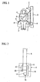
- FIG 1 is a front view of a seatbelt apparatus of a vehicle according to a first embodiment of the present invention.
- FIG 2 is a general view of a retractor of the seatbelt apparatus.
- FIG. 3 is a block diagram of a motor for driving a belt reel in the seatbelt apparatus.
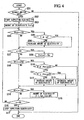
- FIG 4 is a flowchart for controlling current to be supplied to the motor for driving the belt reel in the seatbelt apparatus.
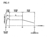
- FIG. 5 is a graph showing the characteristics of the seatbelt apparatus for winding the belt reel.
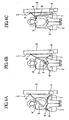
- FIGS. 6A to 6C are front views of the seatbelt apparatus, indicating the winding states of the seatbelt in time series.
- FIG 7 is a flowchart for controlling current to be supplied to a motor for driving a belt reel in a seatbelt apparatus according to a second embodiment of the present invention.
- FIG 8 is a flowchart for controlling current to be supplied to a motor for driving a belt reel in a seatbelt apparatus according to a third embodiment of the present invention.
- FIG. 9 is a graph showing the characteristics of the seatbelt apparatus for winding the belt reel.
- FIG. 10 is a flowchart for controlling current to be supplied to a motor for driving a belt reel in a seatbelt apparatus according to a fourth embodiment of the present invention.
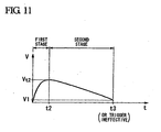
- FIG 11 is a graph showing the characteristics of the seatbelt apparatus for winding the belt reel.
- seatbelt apparatus Embodiments of a seatbelt apparatus of a vehicle according to the present invention (hereinafter “seatbelt apparatus”) will be explained below with reference to the drawings.
- FIG 1 is a general construction of a seatbelt apparatus 1 that, in the present embodiment, restricts an occupant P sitting in a seat 2 of a driver's seat.
- This seatbelt apparatus 1 is a so-called three-point seatbelt apparatus in which: a seatbelt 5 is drawn upward from a retractor 4 installed in a center pillar 3; the seatbelt 5 is inserted through a through anchor 6 supported on an upper side of the center pillar 3; and a distal end of the seatbelt 5 is fixed, via an outer anchor 7 arranged on the vehicular outside of the seat 2, to a floor of a vehicle.
- a tongue 8 is attached between the through anchor 6 of the seatbelt 5 and the outer anchor 7. The tongue 8 is attachable and detachable to a buckle 9 fixed to the floor on a driver's seat 2 side of the vehicle.
- the occupant P sitting on the seat 2 can set it to a fitted state by inserting the tongue 8 into the buckle 9 to engage therewith.
- the occupant P can also set the seatbelt apparatus 1 in a released state by releasing the engagement between the tongue 8 with the buckle 9 and separating the tongue 8 from the buckle 9 (hereinafter, this is sometime referred to as "releasing the buckle 9").
- the buckle 9 is provided with a buckle switch 17.
- the buckle switch 17 is turned ON when the tongue 8 is engaged with the buckle 9 (in other words, in a state where the seatbelt 5 is attached), while the buckle switch 17 is turned OFF when the tongue 8 is released from the buckle 9 (in other words, in a state where the seatbelt 5 is unattached).
- the retractor 4 is mainly provided with: a rotatable belt reel 11 on which the seatbelt 5 is wound; a spring 12 that urges the belt reel 11 so as to rotate in the winding rotational direction thereof; and a motor 14 that applies a rotational power in the winding rotational direction to the belt reel 11 via a transferring device 13 such as gears. Furthermore, the retractor 4 is provided with: a rotational position sensor (winding position detection device) 15 that detects a rotational position (winding position) of the belt reel 11; and a current sensor 16 that measures the current to be supplied to the motor 14.
- a rotational position sensor winding position detection device
- the winding amount of the belt reel 11 is substantially equal to the winding amount of the seatbelt 5.
- the belt reel 11 is rotated in the winding direction by the spring 12, and also could be rotated in the same winding direction by the driving force of the motor 14.
- winding of the belt reel 11 after releasing the buckle 9 is performed by the recovering force of the spring 12, and the rotational force of the motor 14 that is transferred through the transferring device 13.
- the motor 14 is controlled by the motor controller 20, and is driven to wind the belt reel 11 after releasing the buckle 9.
- the motor 14 is also driven to apply the predetermined tension to the seatbelt 5, to support the occupant P at the predetermined position, and to remove the looseness in the seatbelt 5 occurred while traveling, when the predetermined traveling state is detected by a traveling state detection device 18 (for example, when the case is detected in which the output of a sensor that measures the quantity relating to motions of the vehicle such as the acceleration in the car width direction exceeds the predetermined threshold value, or when the case is detected in which changes in the traveling circumstances are detected based on communication information from a navigation system or the like).
- a traveling state detection device 18 for example, when the case is detected in which the output of a sensor that measures the quantity relating to motions of the vehicle such as the acceleration in the car width direction exceeds the predetermined threshold value, or when the case is detected in which changes in the traveling circumstances are detected based on communication information from a navigation system or the like).
- the motor controller (controller) 20 is input with output signals from the rotational position sensor 15, the current sensor 16, and the buckle switch 17. Furthermore, the motor controller 20 is input with an alarming trigger when the traveling state detection device 18 detects the above-mentioned predetermined traveling state.
- the motor controller 20 sets the activation timing and the stop timing, and the target current based on the input signals, and then outputs to a current controller 21.
- the current controller 21 adjusts the activation timing and the stop timing of the motor 14, and the current to be supplied to the motor 14, based on the input from the motor controller 20, and thereby supplies electrical power from the power supply 22 to the motor 14.
- the control routine for controlling the current to be supplied to the motor 14 shown in flowchart of FIG 4 is repeated by the motor controller 20 at constant time intervals.
- step S01 it is determined whether the buckle switch 17 is in OFF or not.
- step S01 If the determination result in step S01 is NO (i.e., ON), then this routine is temporarily ended.
- step S01 determines whether the determination result in step S01 is YES (i.e., OFF). If the determination result in step S01 is YES (i.e., OFF), then the process proceeds to step S02, and supplying the electricity to the motor 14 is started. Then, the process further proceeds to step S03, and the electricity (the current) I to the motor 14 is set to an initial current I 0 that was set in advance.
- first winding position that is the position where the seatbelt 5 is wound for the predetermined amount set in advance (first predetermined amount) from the winding position at the releasing X0 or not.
- the predetermined amount "a” is comparatively set to be a short length such as 50 mm.
- step S04 determines whether the current I to be supplied to the motor 14, that is measured by the current sensor 16 is equal to or larger than an initial current value I 0 or not.
- step S05 determines whether the determination result in step S05 is YES (I ⁇ I 0 ). If the determination result in step S05 is YES (I ⁇ I 0 ), then the process proceeds to step S07 without executing the process of step S06.
- the amount of electricity to be supplied to the motor 14 is set to substantially constant value that is not lower than the initial current value I 0 .
- the winding amount by the belt reel 11 from the winding position at the releasing X0 is less than the predetermined amount a, there are cases in which: the occupant P still does not release the tongue 8 from his/her hand; or the tongue 8 or the seatbelt 5 is easily hooked on the occupant P even though the occupant P has released the tongue 8 from his/her hand.
- the torque by the motor 14 is set so as not to be increased much more, by setting the amount of the electricity to be supplied to the motor 14 be substantially equal to the initial current value I 0 .
- the reason why the first winding position X1 is set to the position where the predetermined amount a is wound from the winding position at the releasing X0, is that the winding position at the releasing X0 changes depending on the physique of the occupant P.
- step S04 determines whether the determination result in step S04 is NO (x ⁇ X1), then the process proceeds to step S07.
- step S07 it is determined whether the current winding position x by the belt reel 11 reaches the first winding position X1 or not.
- the winding speed of the belt reel 11 is calculated based on the amount of change in the winding position of the belt reel 11, which is measured by the rotational position sensor 15.
- step S07 determines whether the determination result in step S07 is NO (x ⁇ X1).
- step S09 it is determined whether the current winding position x of the belt reel 11 is larger than the first winding position X1 and is equal to or less than a second winding position X2, or not.
- the second winding position X2 is set to a position where is more predetermined distance to reach a winding position X3 where the seatbelt 5 is completely housed (hereinafter "a complete winding position"). Therefore, the second winding position X2 is set to the position where the occupant P wearing the seatbelt apparatus 1 can easily remove his/her hand from the seatbelt 5.
- the second winding position X2 also can be said as a winding position where is reachable by further winding a second predetermined amount b from the first winding position X1.
- the second winding position X2 is fixed, and the second predetermined amount b changes in accordance with the winding position at the releasing X0 which changes in accordance with the physique of the occupant P; however, it may be arranged such that the second predetermined amount b is fixed while the second winding position X2 is changeable.
- step S10 it is determined whether the current winding speed V of the belt reel 11 reaches the target winding speed Vtarget set in step S08, or not.
- step S10 If the determination result in step S10 is YES (V ⁇ Vtarget), then the process proceeds to step S11. In this step S11, it is determined whether the current winding speed V of the belt reel 11 is larger than the target winding speed Vtarget or not.
- ⁇ I the predetermined amount
- step S11 If the determination result in step S11 is YES (V > Vtarget), then the process proceeds to step S13.
- step S09 determines whether the determination result in step S09 is NO (x ⁇ X1, or x > X2). If the determination result in step S09 is NO (x ⁇ X1, or x > X2), then the process proceeds to step S 14.
- step S14 it is determined whether the current winding position x of the belt reel 11 is larger than the second winding position X2 and is smaller than the complete winding position X3, or not.
- step S15 the amount of electricity I to be supplied to the motor 14 is set to the current value calculated by the following equation, and the process proceeds to step S16.
- I I X ⁇ 2 - C ⁇ x - X ⁇ 2
- I X2 is a current value to be supplied to the motor 14 when the winding position x of the belt reel 11 reaches the second winding position X2, while C is a coefficient (constant value).
- the current I to be supplied to the motor 14 is controlled so as to be gradually reduced as the winding amount increases, with reference to the current value I X2 of the motor 14 at the time reaching to the second winding position X2.
- the winding speed of the belt reel 11 can be continuously and gradually decreased as approaching to the end of the winding of the belt reel 11. As the result, it is possible to prevent the tongue 8 roughly contacting an interior decoration of the vehicle when the seatbelt 5 is almost completely wound.
- step S14 If the determination result in step S14 is NO (x ⁇ X2, or x > X3), then the process proceeds to step S16.
- step S16 it is determined whether the current winding position x of the belt reel 11 reaches the complete winding position X3 or not.
- step S16 If the determination result in step S16 is NO (x ⁇ X3), then the process returns to step S04, and the processes from step S04 to step S16 are repeated.
- FIG. 5 The winding characteristic when the amount of electricity to the motor 14 is controlled as explained in the above is shown in FIG. 5 .
- the horizontal axis indicates the winding position x of the belt reel 11, while the vertical axis indicates the winding speed V of the belt reel 11.
- a first stage from the winding position at the releasing X0 to the first winding position X1 corresponds to an initial region of winding of the seatbelt 5.
- the amount of electricity to be supplied to the motor 14 is controlled to be substantially constant, and the winding speed by the belt reel 11 gradually increases.
- the first stage by controlling the amount of electricity to be supplied to the motor 14 so as to be substantially constant, as explained in the above, it is possible to prevent the excessive tension applied on the seatbelt 5 when the tongue 8 is held by the occupant P or when the tongue 8 or the seatbelt 5 is hooked onto the occupant P. As the result, it is possible to prevent causing uncomfortableness to the occupant P.
- the second stage from the first winding position X1 to the second winding position X2 is, as shown in FIG 6B , a middle region for winding the seatbelt 5.
- the initial value for a control target (the target winding speed Vtarget) at the second stage is set based on the winding speed (changing amount in the winding position) of the belt reel 11; and in the second stage, the amount of electricity to be supplied to the motor 14 is controlled such that the winding speed V of the belt reel 11 is maintained to the target winding speed Vtarget (i.e., based on the predetermined rule).
- the seatbelt 5 is wound stably and smoothly.
- the initial value for a control target (the target winding speed Vtarget) in the second stage is set based on the winding speed (the amount of change in the winding position) V X1 of the belt reel 11 in the first winding position X1. Accordingly, the continuity while shifting from the first stage to the second stage is maintained, and thereby preventing causing uncomfortableness to the occupant P.
- the third stage from the second winding position X2 to the complete winding position X3 is a final region for winding the seatbelt 5.
- the current I to be supplied to the motor 14 is controlled so as to be gradually decreased as the amount of winding increases, based on the current value I X2 of the motor 14 at the time when the current I to be supplied to the motor 14 reaches the second winding position X2.
- the third stage it is possible to continuously and gradually decrease the winding speed of the belt reel 11 as approaching to the end of winding of the belt reel 11, from the winding speed at the second winding position X2 (i.e., the winding speed V X1 at the first winding position X1). As the result, it is possible to prevent the tongue 8 roughly contacting an interior decoration of the vehicle when the seatbelt 5 is almost completely wound.
- control-stopping interval for suddenly reducing the amount of electricity to be supplied to the motor 14 (for example, reducing the current value to zero) while shifting from the second stage to the third stage.
- the occupant P can remove his/her hand from the seatbelt 5 easily.
- the first stage corresponds to the first control mode
- the second stage and the third stage correspond to the second control mode
- the seatbelt apparatus 1 of the present embodiment has the same construction as that of the first embodiment; therefore, explanation therefor will be omitted here.
- the present embodiment differs from the first embodiment in a current control of the motor 14 while winding the belt reel after releasing the buckle 9.
- FIG 7 is a flowchart showing the current control of the motor 14 of the present embodiment.
- the stop timing of the second stage is set to the time when the winding position x of the belt reel 11 reaches the second winding position X2; however, in the present embodiment, the stop timing of the second stage is set to the time when the predetermined time has passed after reaching to the first winding position X1.
- steps S101 to S107 are same as those of steps S01 to S07 in the first embodiment; therefore, the explanations therefor will be omitted here.
- step S107 determines whether the determination result in step S107 is NO (x ⁇ X1). If the determination result in step S107 is NO (x ⁇ X1), then the process proceeds to step S109.
- step S109 it is determined: whether the current winding position x of the belt reel 11 is smaller than the complete winding position X3 and is larger than the first winding position X1; and the elapsed time is equal to or less than the predetermined time t1 which was set in advance.
- step S109 If the determination result in step S109 is YES (X 1 ⁇ x ⁇ X3, and t ⁇ t1), then the process proceeds to step S110. On the other hand, if the determination result in step S109 is NO (x ⁇ X1, or x ⁇ X3, or t > t1), then the process proceeds to step S114.
- steps S110 to S113 are the same as those of steps S10 to S13 of the first embodiment; therefore, explanations therefor will be omitted here.
- step S114 it is determined whether (i) the current winding position x of the belt reel 11 is larger than the first winding position X1 and is smaller than the complete winding position X3, and (ii) the elapsed time has exceeded the predetermined time t1.
- step S115 the amount of electricity I to be supplied to the motor 14 is set to the current value calculated by the following equation, and the process proceeds to step S116.
- I I t ⁇ 1 - C ⁇ t - t ⁇ 1
- I t1 is a current value of the motor 14 at the time when the predetermined time t1 has elapsed after the winding position x of the belt reel 11 reaches to the first winding position X1
- C is a coefficient (constant value).
- the current I to be supplied to the motor 14 is controlled so as to be gradually reduced as time passes, with reference to the current I t1 of the motor 14 at the time when the predetermined time t1 has passed.
- the winding speed of the belt reel 11 can be continuously and gradually reduced as approaching to the end of winding of the belt reel 11. As the result, it is possible to prevent the tongue 8 roughly contacting an interior decoration of the vehicle when the seatbelt 5 is almost completely wound.
- step S114 If the determination result in step S114 is NO (x ⁇ X1, or x ⁇ X3, or t ⁇ t1), then the process proceeds to step S116.
- steps S116 and S117 are the same as those of steps S16 and S 17 of the first embodiment; therefore, explanation therefor will be omitted here.
- the seatbelt apparatus 1 of the present embodiment can also obtain the same operations and advantageous effects as those of the first embodiment.
- the first stage corresponds to the first control mode
- the second stage and the third stage correspond to the second control mode
- the seatbelt apparatus 1 of the present embodiment has the same construction as that of the first embodiment; therefore, explanation therefor will be omitted here.
- the present embodiment differs from the first embodiment in a current control of the motor 14 while winding the belt reel after releasing the buckle 9.
- FIG 8 is a flowchart showing a current control of the motor 14 of the present embodiment.
- the second stage for controlling the winding speed of the belt reel 11 to be the constant, and (ii) the third stage for gradually reducing the winding speed V of the belt reel 11 by gradually reducing the amount of electricity are executed after the winding position x of the belt reel 11 has reached to the first winding position X1 (i.e., after the first stage).
- the present embodiment as shown in a graph of FIG.
- a stage for controlling the winding speed of the belt reel 11 to be constant i.e., the second stage in the first embodiment
- a stage for gradually reducing the winding speed V of the belt reel 11 i.e., the second stage in the present embodiment
- steps S201 to S208 are the same as those of steps S01 to S08 in the first embodiment; therefore, the explanations therefor will be omitted here.
- step S207 determines whether the determination result in step S207 is NO (x ⁇ X1), or when the process of step S208 has been executed, the process proceeds to step S209.
- step S209 it is determined whether the current winding position x of the belt reel 11 is larger than the first winding position X1 and is smaller than the complete winding position X3, or not.
- step S210 the target winding speed Vtarget of the belt reel 11 is set to the winding speed calculated by the following equation.
- Vtarget V X ⁇ 1 - C ⁇ x - X ⁇ 1
- V X1 is the winding speed of the belt reel 11 at the time when the winding position x of the belt reel 11 reaches the first winding position X1, while C is a coefficient (constant value).
- the winding speed V of the belt reel 11 is set so as to gradually decreases as the amount of winding increases, with reference to the winding speed V X1 at the time of reaching to the first winding position X1.
- step S210 proceeds from step S210 to S211, and it is determined whether the current winding speed V of the belt reel 11 matches with the target winding speed Vtarget that was set in step S210.
- step S211 If the determination result in step S211 is YES (V ⁇ Vtarget), then the process proceeds to step S212. In this step S212, it is determined whether the current winding speed V of the belt reel 11 is larger than the target winding speed Vtarget or not.
- ⁇ I predetermined amount
- step S212 If the determination result in step S212 is YES (V > Vtarget), then the process proceeds to step S214.
- the amount of electricity to be supplied to the motor 14 is controlled such that the winding speed V of the belt reel 11 gradually decreases as approaching to the end of winding of the belt reel 11.
- step S209 If the determination result in step S209 is NO (x ⁇ X1, or x ⁇ X3), then the process proceeds to step S215.
- steps S215 and S216 are same as those of steps S16 and S17 of the first embodiment; therefore, the explanations therefor will be omitted here.
- the amount of electricity to be supplied to the motor 14 is controlled so as to be substantially constant in the first stage from the winding position at the releasing X0 to the first winding position X1. Accordingly, it is possible to prevent the excessive tension applied onto the seatbelt 5 when the tongue 8 is held by the occupant P or when the tongue 8 or the seatbelt 5 is hooked on the occupant P. As the result, it is possible to prevent causing uncomfortableness to the occupant P.
- the initial value for a control target (the target winding speed Vtarget) in the second stage is set based on the winding speed (the amount of change in the winding position) V X1 of the belt reel 11 in the first winding position X1. Accordingly, the continuity while shifting from the first stage to the second stage is maintained, and thereby preventing causing uncomfortableness to the occupant P.
- the current I to be supplied to the motor 14 is controlled such that the winding speed of the belt reel 11 continuously and gradually decreases as approaching to the end of winding of the belt reel 11, from the winding speed V X1 at the time of reaching to the first winding position X1 (that is, based on the predetermined rule).
- the first stage corresponds to the first control mode
- the second stage corresponds to the second control mode
- the seatbelt apparatus 1 of the present embodiment has the same construction as that of the first embodiment; therefore, explanation therefor will be omitted here.
- the motor 14 is activated to wind the belt reel 11 while releasing the buckle 9.
- the motor 14 is activated to: remove the looseness in the seatbelt 5, that arises while traveling the vehicle; or to remove the looseness in the seatbelt 5 by applying the predetermined tension to the seatbelt 5 when the predetermined traveling state is detected by the traveling state detection device 18.
- a current control routine of the motor 14 shown in the flowchart of FIG 10 is repeated at each predetermined timings by the motor controller 20.
- step S301 it is determined whether an operation trigger is effective or not.
- the operation trigger is determined to be effective when the looseness in the seatbelt 5 while traveling is detected or when the predetermined traveling state is detected by the traveling state detection device 18.
- step S301 If the determination result in step S301 is NO (ineffective), then the execution of the present routine is temporarily ended.
- step S302 the supply of the electricity to the motor 14 is started, and then the process proceeds to step S303.
- step S304 the amount of electricity (current) I to be supplied to the motor 14 is set to the initial current value I 0 that is set in advance.
- step S305 it is determined whether the elapsed time after staring counting timer is equal to or larger than the first predetermined time t1 and less than the second predetermined time t2.
- step S305 If the determination result in step S305 is YES (t1 ⁇ t ⁇ t2), then the process proceeds to step S306. In this step S306, it is determined whether the current I to be supplied to the motor 14 that is measured by the current sensor 16 is equal to or larger than the initial current value I 0 .
- step S306 If the determination result in step S306 is NO (I ⁇ I 0 ), then the process proceeds to step S307.
- step S306 determines whether the determination result in step S306 is YES (I ⁇ I 0 ). If the determination result in step S306 is YES (I ⁇ I 0 ), then the process proceeds to step S308 without executing the process of step S307.
- the amount of electricity to be supplied to the motor 14 is set to be the constant value which is not lower than the initial current value I 0 .
- the torque of the motor 14 can be controlled so as not to be increased much more. Accordingly, it is possible to prevent the excessive tension applied onto the seatbelt 5 when the tongue 8 is held by the occupant P or when the tongue 8 or the seatbelt 5 is hooked onto the occupant P. As the result, it is possible to prevent causing uncomfortableness to the occupant P.
- step S305 determines whether the determination result in step S305 is NO (t ⁇ t1, or t ⁇ t2). Also in the case in which the determination result in step S305 is NO (t ⁇ t1, or t ⁇ t2), the process proceeds to step S308.
- step S308 it is determined whether the elapsed time has reached the second predetermined time t2 or not.
- the winding speed of the belt reel 11 is calculated based on the amount of change in the winding position of the belt reel 11 that is measured by the rotational position sensor 15.
- step S308 determines whether the determination result in step S308 is NO (t ⁇ t2), then the process proceeds to step S310.
- step S310 it is determined whether the elapsed time has exceeded the second predetermined time t2 or not
- step S310 If the determination result in step S310 is YES (t > t2), then the process proceeds to step S311.
- the target winding speed Vtarget of the belt reel 11 is set o the winding speed that is calculated by the following equation.
- Vtarget V t ⁇ 2 - C ⁇ t - t ⁇ 2 where C is a coefficient (constant value).
- the winding speed V of the belt reel 11 is set so as to be gradually decreased as time passes, with reference to the winding speed V t2 at the second predetermined time t2.
- step S311 the process proceeds from step S311 to step S312, and it is determined whether the target winding speed Vtarget that is set in step S311 is equal to or less than the winding speed V1 that was set in advance. Moreover, the first winding speed V1 is set to the value that is close to but is larger than zero.
- step S312 determines whether the determination result in step S312 is YES (Vtarget ⁇ V1), then the process proceeds to step S313.
- step S312 determines whether the determination result in step S312 is NO (Vtarget > V1).
- step S314 it is determined whether the current winding speed V of the belt reel 11 has reached the target winding speed Vtarget or not.
- step S314 If the determination result in step S314 is YES (V ⁇ Vtarget), then the process proceeds to step S315.
- step S315 it is determined whether the current the winding speed V of the belt reel 11 is larger than the target winding speed Vtarget or not.
- step S315 If the determination result in step S315 is NO (V ⁇ Vtarget), then the process proceeds to step S316.
- step S315 If the determination result in step S315 is YES (V > Vtarget), then the process proceeds to step S317.
- the amount of electricity to be supplied to the motor 14 is controlled such that the winding speed V of the belt reel 11 gradually decreases as approaching to the end of winding of the belt reel 11.
- step S310 determines whether the determination result in step S310 is NO (t ⁇ t2), then the process proceeds to step S318.
- step S318 it is determined whether one of (i) the elapsed time has reached to the third predetermined time t3, and (ii) the operation trigger is ineffective, is satisfied or not
- step S318 If the determination result in step S318 is NO (t ⁇ t3, and the operation trigger is effective), then the process is returned to step S305, and the processes from step S305 to step S318 are repeated.
- step S319 the electricity to be supplied to the motor 14 is stopped, and the execution of the present routine is temporarily ended.
- a winding characteristic of the present embodiment is shown in FIG 11 .
- the second predetermined time t2 is a first stage where the amount of electricity to be supplied to the motor 14 is controlled to be the substantially constant value.
- the second predetermined time t2 is a second stage where the amount of electricity to be supplied to the motor 14 is controlled such that the winding speed of the belt reel 11 gradually decreases.
- the amount of electricity to be supplied to the motor 14 is controlled so as to be the substantially constant; therefore, it is possible to prevent the excessive tension applied onto the seatbelt 5 when the tongue 8 is held by the occupant P or when the tongue 8 or the seatbelt 5 is hooked to the occupant P. As the result, it is possible to prevent causing uncomfortableness to the occupant P.
- the initial value for a control target (the target winding speed Vtarget) in the second stage is set based on the winding speed (the amount of change in the winding position) V t2 . Accordingly, the continuity while shifting from the first stage to the second stage is maintained, and thereby preventing causing uncomfortableness to the occupant P.
- the current I to be supplied to the motor 14 is controlled such that the winding speed of the belt reel 11 continuously and gradually decreases as approaching to the end of removing the looseness in the seatbelt 5, from the winding speed V t2 that is the winding speed at the time when the belt reel 11 has reached to the second predetermined time t2 (i.e., based on the predetermined rule). Accordingly, the looseness in the seatbelt 5 can be removed stably and smoothly.
- the first stage is the first control mode
- the second stage is the second control mode
- the present invention is not limited only to the above-mentioned embodiments.
- the amount of electricity I is controlled so as to be increased when the actual amount of electricity I to be supplied to the motor 14 is smaller than the initial current value I 0 (refer to steps S05, S06, S105, S106, S205, S206, S306, and S307).
- a feedback control may be executed in which the amount of electricity is decreased when the actual amount of electricity I to be supplied to the motor 14 is larger than the initial current value I 0 , thereby controlling the amount of electricity I to be supplied to the motor 14 becomes constant value of the initial current value I 0 .
- the current control to the motor 14 may not be executed after setting the amount of electricity to be supplied to the motor 14, to the initial current value I 0 and the supplying of the electricity is started. That is, in the first control mode, the amount of electricity to be supplied to the motor 14 may not be exactly constant, if only it is almost constant.
- the winding speed of the belt reel 11 is gradually decreased, in the second control mode, as approaching to the end of completion of winding or the end of removing the looseness in the seatbelt 5, so as to follow the linear function; however, the present invention is not limited to this. Instead of this, any reduction process may be employed if only the winding speed could be continuously and gradually decreased.
- This seatbelt apparatus of a vehicle is provided with: a seatbelt; a belt reel on which the seatbelt is wound; a motor that drives a rotation of the belt reel; a controller that controls a driving amount of the motor; a winding position detection device that detects a winding position of the belt reel.
- the controller performs a first control mode in which a substantially constant electricity is supplied to the motor, and a second control mode in which the electricity supplied to the motor is controlled based on a predetermined rule; and sets an initial value for the second control mode based on changes in the winding position detected by the winding position detection device, while changing from the first control mode to the second control mode.
Landscapes
- Engineering & Computer Science (AREA)
- Mechanical Engineering (AREA)
- Automotive Seat Belt Assembly (AREA)
Claims (3)
- Sicherheitsgurtvorrichtung eines Fahrzeugs, umfassend:einen Sicherheitsgurt (5);eine Gurtrolle (11), auf die der Sicherheitsgurt (5) gewickelt ist;einen Motor (14), der die Gurtrolle (11) drehend antreibt;einen Controller (20), der einen Antriebsbetrag des Motors (14) steuert/regelt;eine Wickelpositionserfassungsvorrichtung (15), die eine Wickelposition der Gurtrolle (11) erfasst;eine Zunge (8), durch die der Sicherheitsgurt eingeführt wird;ein Schloss (9), das mit der Zunge (8) lösbar in Eingriff tritt, um den Sicherheitsgurt (5) in einen angelegten Zustand zu bringen; undeine Schlosszustanderfassungsvorrichtung (17), die einen Eingriffs/Lösezustand des Schlosses (9) mit der Zunge (8) erfasst,worin der Controller (5) einen ersten Steuermodus, in dem dem Motor (14) eine im Wesentlichen konstante Elektrizität zugeführt wird, wenn die Schlosszustanderfassungsvorrichtung (17) ein Lösen der Zunge (8) von dem Schloss (9) erfasst, und einen zweiten Steuermodus, in dem die dem Motor (14) zugeführte Elektrizität basierend auf einer vorbestimmten Regel gesteuert/geregelt wird, wenn die Wickelpositionserfassungsvorrichtung (15) erfasst, dass der Sicherheitsgurt (5) um einen ersten vorbestimmten Betrag (a) gewickelt ist, nachdem das Lösen der Zunge (8) von dem Schloss (9) erfasst worden ist, durchführt, und während des Wechsels von dem ersten Steuermodus zum zweiten Steuermodus einen Anfangswert für den zweiten Steuermodus basierend auf Änderungen in der von der Wickelpositionserfassungsvorrichtung (15) erfassten Wickelposition setzt,
dadurch gekennzeichnet, dass der Controller (20) den zweiten Steuermodus so ausführt, dass eine Wickelgeschwindigkeit von einer dann vorliegenden Wickelgeschwindigkeit, wenn der Sicherheitsgurt (5) um den ersten vorbestimmten Betrag (a) gewickelt ist, bis der Sicherheitsgurt (5) seine vollständige Wickelposition (X3) erreicht hat, kontinuierlich abnimmt. - Sicherheitsgurtvorrichtung eines Fahrzeugs nach Anspruch 1, worin der Controller (20) den zweiten Steuermodus so ausführt, dass für eine vorbestimmte Zeit die Wickelgeschwindigkeit dann, wenn der Sicherheitsgurt (5) um den ersten vorbestimmten Betrag (a) gewickelt ist, bevor die Wickelgeschwindigkeit kontinuierlich abnimmt, beibehalten wird.
- Sicherheitsgurtvorrichtung eines Fahrzeugs nach Anspruch 1, worin der Controller (20) den zweiten Steuermodus so ausführt, dass die Wickelgeschwindigkeit dann, wenn der Sicherheitsgurt um den ersten vorbestimmten Betrag (a) gewickelt ist, mit einem Intervall ab dann, wenn der Sicherheitsgurt (5) um den ersten vorbestimmten Betrag (a) gewickelt ist, bis dann, wenn der Sicherheitsgurt (5) um einen zweiten vorbestimmten Betrag weiter gewickelt ist, beibehalten wird, und
worin der Controller (20) den zweiten Steuermodus so durchführt, dass eine Wickelgeschwindigkeit von der dann vorliegenden Wickelgeschwindigkeit, wenn der Sicherheitsgurt (5) um den ersten vorbestimmten Betrag (a) gewickelt ist, in einem Intervall ab dann, wenn der Sicherheitsgurt (5) um den zweiten vorbestimmten Betrag gewickelt ist, bis dann, wenn der Sicherheitsgurt (5) vollständig aufgewickelt ist, kontinuierlich abnimmt.
Applications Claiming Priority (1)
| Application Number | Priority Date | Filing Date | Title |
|---|---|---|---|
| JP2006305187A JP4959296B2 (ja) | 2006-11-10 | 2006-11-10 | 車両のシートベルト装置 |
Publications (2)
| Publication Number | Publication Date |
|---|---|
| EP1920977A1 EP1920977A1 (de) | 2008-05-14 |
| EP1920977B1 true EP1920977B1 (de) | 2009-09-02 |
Family
ID=39111547
Family Applications (1)
| Application Number | Title | Priority Date | Filing Date |
|---|---|---|---|
| EP07021729A Not-in-force EP1920977B1 (de) | 2006-11-10 | 2007-11-08 | Sicherheitsgurtvorrichtung für ein Fahrzeug |
Country Status (4)
| Country | Link |
|---|---|
| US (1) | US8109460B2 (de) |
| EP (1) | EP1920977B1 (de) |
| JP (1) | JP4959296B2 (de) |
| DE (1) | DE602007002247D1 (de) |
Cited By (1)
| Publication number | Priority date | Publication date | Assignee | Title |
|---|---|---|---|---|
| CN103909898A (zh) * | 2013-01-09 | 2014-07-09 | 本田技研工业株式会社 | 安全带装置 |
Families Citing this family (6)
| Publication number | Priority date | Publication date | Assignee | Title |
|---|---|---|---|---|
| JP4889579B2 (ja) * | 2007-06-26 | 2012-03-07 | 本田技研工業株式会社 | 車両のシートベルト装置 |
| JP4603066B2 (ja) * | 2008-09-04 | 2010-12-22 | 本田技研工業株式会社 | 車両のシートベルト装置およびその制御方法 |
| JP2010111334A (ja) * | 2008-11-07 | 2010-05-20 | Takata Corp | シートベルト装置、シートベルト制御装置、シートベルト制御方法、及びプログラム |
| JP5642161B2 (ja) * | 2010-04-23 | 2014-12-17 | 本田技研工業株式会社 | シートベルト装置 |
| JP5504236B2 (ja) * | 2011-10-11 | 2014-05-28 | 本田技研工業株式会社 | シートベルトの制御装置 |
| US11117545B2 (en) * | 2019-04-19 | 2021-09-14 | GM Global Technology Operations LLC | System and method for determining seatbelt routing |
Family Cites Families (14)
| Publication number | Priority date | Publication date | Assignee | Title |
|---|---|---|---|---|
| US6702056B2 (en) | 1997-08-06 | 2004-03-09 | Takata Corporation | Seatbelt retractor |
| JP4662225B2 (ja) | 2001-09-12 | 2011-03-30 | タカタ株式会社 | シートベルト巻取装置 |
| US6257363B1 (en) * | 1997-12-16 | 2001-07-10 | Nsk Ltd. | Automotive passenger restraint and protection apparatus |
| JP4052491B2 (ja) * | 1998-03-24 | 2008-02-27 | オートリブ株式会社 | 車両用乗員拘束保護装置 |
| JP4467688B2 (ja) | 1999-01-19 | 2010-05-26 | タカタ株式会社 | シートベルト巻取装置 |
| DE10061040A1 (de) * | 2000-12-08 | 2002-06-13 | Daimler Chrysler Ag | Verfahren zur Ansteuerung eines reversiblen Gurtstraffers |
| JP4244213B2 (ja) * | 2002-12-26 | 2009-03-25 | 株式会社デンソー | 車両用安全装置 |
| DE10336122B4 (de) * | 2003-08-06 | 2006-04-06 | Key Safety Systems, Inc., Sterling Heights | Verfahren und Vorrichtung zur Einstellung eines Versorgungsstromes für einen Elektromotor, dessen Drehmoment auf eine Gurtspule eines Sicherheitsgurtaufrollers eines Kraftfahrzeugs übertragen wird |
| JP4472299B2 (ja) * | 2003-09-25 | 2010-06-02 | タカタ株式会社 | モータ付シートベルト巻き取り装置の制御方法及び装置 |
| JP4371365B2 (ja) * | 2004-05-13 | 2009-11-25 | タカタ株式会社 | シートベルト巻き取り装置における巻き取り制御方法、及びシートベルト装置 |
| JP4573225B2 (ja) * | 2004-09-24 | 2010-11-04 | タカタ株式会社 | シートベルトの巻き取り方法 |
| JP4570141B2 (ja) * | 2004-10-05 | 2010-10-27 | タカタ株式会社 | シートベルト巻き取り装置及びシートベルト装置 |
| DE102004054078B4 (de) * | 2004-11-09 | 2013-03-07 | Key Safety Systems, Inc. | Verfahren zum Blockieren einer Wickelwelle eines Sicherheitsgurtaufrollers |
| JP4652022B2 (ja) * | 2004-11-19 | 2011-03-16 | オートリブ ディベロップメント エービー | シートベルト用リトラクタおよびシートベルト装置 |
-
2006
- 2006-11-10 JP JP2006305187A patent/JP4959296B2/ja not_active Expired - Fee Related
-
2007
- 2007-11-08 EP EP07021729A patent/EP1920977B1/de not_active Not-in-force
- 2007-11-08 DE DE602007002247T patent/DE602007002247D1/de active Active
- 2007-11-09 US US11/937,662 patent/US8109460B2/en active Active
Cited By (2)
| Publication number | Priority date | Publication date | Assignee | Title |
|---|---|---|---|---|
| CN103909898A (zh) * | 2013-01-09 | 2014-07-09 | 本田技研工业株式会社 | 安全带装置 |
| CN103909898B (zh) * | 2013-01-09 | 2016-08-17 | 本田技研工业株式会社 | 安全带装置 |
Also Published As
| Publication number | Publication date |
|---|---|
| JP4959296B2 (ja) | 2012-06-20 |
| EP1920977A1 (de) | 2008-05-14 |
| DE602007002247D1 (de) | 2009-10-15 |
| US8109460B2 (en) | 2012-02-07 |
| JP2008120194A (ja) | 2008-05-29 |
| US20080173748A1 (en) | 2008-07-24 |
Similar Documents
| Publication | Publication Date | Title |
|---|---|---|
| EP1920977A1 (de) | Sicherheitsgurtvorrichtung für ein Fahrzeug | |
| JP4919895B2 (ja) | 車両のシートベルト装置およびその制御方法 | |
| US8046136B2 (en) | Vehicle seatbelt apparatus, vehicle having the vehicle seatbelt apparatus and method for controlling vehicle seatbelt | |
| EP1738978A1 (de) | Sicherheitsgurtaufroller, Sicherheitsgurteinrichtung und Fahrzeug mit einer Sicherheitsgurteinrichtung | |
| EP1790540A1 (de) | Sitzgurtstraffer, Sitzgurtvorrichtung und Fahrzeug mit einer Sitzgurtvorrichtung | |
| JPH04278858A (ja) | 自動車の膝保護装置 | |
| JP5468134B2 (ja) | 乗員保護装置 | |
| EP1749716B1 (de) | Sitzgurtstraffersystem, Sitzgurtvorrichtung und Fahrzeug mit einer Sitzgurtvorrichtung | |
| EP1518766A1 (de) | Verfahren zur Steuerung eines Sicherheitsgurtaufrollgeräts und Vorrichtung dafür. | |
| JP4705058B2 (ja) | モータ駆動シートベルト装置 | |
| JP4573225B2 (ja) | シートベルトの巻き取り方法 | |
| EP1749717A1 (de) | Sicherheitsgurtaufroller, Sicherheitsgurteinrichtung und Fahrzeug mit einer Sicherheitsgurteinrichtung | |
| EP1759938A1 (de) | Sicherheitsgurtanordnung fur ein Fahrzeug | |
| EP1777127B1 (de) | Gurtaufroller, Sicherheitsgurtvorrichtung und Fahrzeug mit einer Sicherheitsgurtvorrichtung | |
| JP5210745B2 (ja) | 車両のシートベルト装置およびその制御方法 | |
| EP1595759A1 (de) | Verfahren zur Steuerung eines Sicherheitsgurtaufroller und ein Sicherheitsgurtaufroller | |
| JP2010089562A (ja) | シートベルト装置 | |
| JP5210780B2 (ja) | 車両のシートベルト装置 | |
| US20130049341A1 (en) | Restraint device | |
| JP4902382B2 (ja) | シートベルト装置 | |
| JP4980083B2 (ja) | 車両のシートベルト装置 | |
| JP5504236B2 (ja) | シートベルトの制御装置 | |
| EP3246216B1 (de) | Sitzgurtaufnahmevorrichtung und sitzgurtvorrichtung | |
| EP1803616B1 (de) | Sitzgurtaufroller, Sitzgurtvorrichtung, und Fahrzeug mit Sitzgurtvorrichtung | |
| US7905519B2 (en) | Vehicle seatbelt apparatus |
Legal Events
| Date | Code | Title | Description |
|---|---|---|---|
| PUAI | Public reference made under article 153(3) epc to a published international application that has entered the european phase |
Free format text: ORIGINAL CODE: 0009012 |
|
| 17P | Request for examination filed |
Effective date: 20071108 |
|
| AK | Designated contracting states |
Kind code of ref document: A1 Designated state(s): AT BE BG CH CY CZ DE DK EE ES FI FR GB GR HU IE IS IT LI LT LU LV MC MT NL PL PT RO SE SI SK TR |
|
| AX | Request for extension of the european patent |
Extension state: AL BA HR MK RS |
|
| 17Q | First examination report despatched |
Effective date: 20080708 |
|
| AKX | Designation fees paid |
Designated state(s): DE FR GB |
|
| GRAP | Despatch of communication of intention to grant a patent |
Free format text: ORIGINAL CODE: EPIDOSNIGR1 |
|
| GRAS | Grant fee paid |
Free format text: ORIGINAL CODE: EPIDOSNIGR3 |
|
| RAP1 | Party data changed (applicant data changed or rights of an application transferred) |
Owner name: HONDA MOTOR CO., LTD. |
|
| GRAA | (expected) grant |
Free format text: ORIGINAL CODE: 0009210 |
|
| AK | Designated contracting states |
Kind code of ref document: B1 Designated state(s): DE FR GB |
|
| REF | Corresponds to: |
Ref document number: 602007002247 Country of ref document: DE Date of ref document: 20091015 Kind code of ref document: P |
|
| PLBE | No opposition filed within time limit |
Free format text: ORIGINAL CODE: 0009261 |
|
| STAA | Information on the status of an ep patent application or granted ep patent |
Free format text: STATUS: NO OPPOSITION FILED WITHIN TIME LIMIT |
|
| 26N | No opposition filed |
Effective date: 20100603 |
|
| REG | Reference to a national code |
Ref country code: DE Ref legal event code: R084 Ref document number: 602007002247 Country of ref document: DE |
|
| REG | Reference to a national code |
Ref country code: GB Ref legal event code: 746 Effective date: 20150709 |
|
| REG | Reference to a national code |
Ref country code: FR Ref legal event code: PLFP Year of fee payment: 9 |
|
| PGFP | Annual fee paid to national office [announced via postgrant information from national office to epo] |
Ref country code: FR Payment date: 20151008 Year of fee payment: 9 |
|
| PGFP | Annual fee paid to national office [announced via postgrant information from national office to epo] |
Ref country code: GB Payment date: 20161102 Year of fee payment: 10 |
|
| REG | Reference to a national code |
Ref country code: FR Ref legal event code: ST Effective date: 20170731 |
|
| PG25 | Lapsed in a contracting state [announced via postgrant information from national office to epo] |
Ref country code: FR Free format text: LAPSE BECAUSE OF NON-PAYMENT OF DUE FEES Effective date: 20161130 |
|
| GBPC | Gb: european patent ceased through non-payment of renewal fee |
Effective date: 20171108 |
|
| PG25 | Lapsed in a contracting state [announced via postgrant information from national office to epo] |
Ref country code: GB Free format text: LAPSE BECAUSE OF NON-PAYMENT OF DUE FEES Effective date: 20171108 |
|
| PGFP | Annual fee paid to national office [announced via postgrant information from national office to epo] |
Ref country code: DE Payment date: 20210923 Year of fee payment: 15 |
|
| REG | Reference to a national code |
Ref country code: DE Ref legal event code: R119 Ref document number: 602007002247 Country of ref document: DE |
|
| PG25 | Lapsed in a contracting state [announced via postgrant information from national office to epo] |
Ref country code: DE Free format text: LAPSE BECAUSE OF NON-PAYMENT OF DUE FEES Effective date: 20230601 |