EP1907077B1 - Ski, insbesondere touren- oder langlaufski, und abstoss- und/oder steighilfe dafür - Google Patents
Ski, insbesondere touren- oder langlaufski, und abstoss- und/oder steighilfe dafür Download PDFInfo
- Publication number
- EP1907077B1 EP1907077B1 EP06795070.9A EP06795070A EP1907077B1 EP 1907077 B1 EP1907077 B1 EP 1907077B1 EP 06795070 A EP06795070 A EP 06795070A EP 1907077 B1 EP1907077 B1 EP 1907077B1
- Authority
- EP
- European Patent Office
- Prior art keywords
- ski
- fur
- strip
- tread
- plate
- Prior art date
- Legal status (The legal status is an assumption and is not a legal conclusion. Google has not performed a legal analysis and makes no representation as to the accuracy of the status listed.)
- Not-in-force
Links
- 230000009194 climbing Effects 0.000 title description 11
- 230000007704 transition Effects 0.000 claims description 26
- 239000004033 plastic Substances 0.000 claims description 10
- 229920003023 plastic Polymers 0.000 claims description 10
- 238000005056 compaction Methods 0.000 claims description 5
- 239000002184 metal Substances 0.000 claims description 5
- 230000008018 melting Effects 0.000 claims description 4
- 238000002844 melting Methods 0.000 claims description 4
- 239000000463 material Substances 0.000 claims description 3
- 230000001846 repelling effect Effects 0.000 description 8
- 230000001070 adhesive effect Effects 0.000 description 4
- 239000000835 fiber Substances 0.000 description 4
- 239000012790 adhesive layer Substances 0.000 description 3
- 230000035515 penetration Effects 0.000 description 3
- 239000000853 adhesive Substances 0.000 description 2
- 229910001220 stainless steel Inorganic materials 0.000 description 2
- 239000010935 stainless steel Substances 0.000 description 2
- 239000004952 Polyamide Substances 0.000 description 1
- 239000004698 Polyethylene Substances 0.000 description 1
- 238000009825 accumulation Methods 0.000 description 1
- 230000002411 adverse Effects 0.000 description 1
- 239000012237 artificial material Substances 0.000 description 1
- 230000006835 compression Effects 0.000 description 1
- 238000007906 compression Methods 0.000 description 1
- 230000003247 decreasing effect Effects 0.000 description 1
- 230000000694 effects Effects 0.000 description 1
- 230000001771 impaired effect Effects 0.000 description 1
- 239000000155 melt Substances 0.000 description 1
- 230000000149 penetrating effect Effects 0.000 description 1
- 229920002647 polyamide Polymers 0.000 description 1
- -1 polyethylene Polymers 0.000 description 1
- 229920000573 polyethylene Polymers 0.000 description 1
- 239000012209 synthetic fiber Substances 0.000 description 1
- 229920002994 synthetic fiber Polymers 0.000 description 1
- 239000004753 textile Substances 0.000 description 1
Images
Classifications
-
- A—HUMAN NECESSITIES
- A63—SPORTS; GAMES; AMUSEMENTS
- A63C—SKATES; SKIS; ROLLER SKATES; DESIGN OR LAYOUT OF COURTS, RINKS OR THE LIKE
- A63C7/00—Devices preventing skis from slipping back; Ski-stoppers or ski-brakes
- A63C7/04—Fastening-devices for skins
Definitions
- the invention relates to a ski, in particular touring or cross-country skis, od with a on the tread, especially in the central region thereof aufklebbaren strips of natural or artificial fur. Like.
- a repelling and / or climbing aid effective material for a repelling and / or climbing aid effective material.
- the present invention relates to a corresponding repelling and / or climbing aid.
- a ski of the type mentioned is for example from the WO 2004/064949 A1 known.
- skins which are glued to the tread of the ski.
- Both natural and artificial, ie made of synthetic fibers skins are used.
- the hair or fibers are aligned so that they stand up during the recoil and provide a corresponding resistance, so that a ski mountaineer can easily master a climb.
- the known skins can be glued to the tread of a ski.
- the skins are stretched over the tread, usually over the entire length of the ski.
- the front end of the hide can then be pinched between the raised plate and the ski so that the front end of the fur is mechanically secured in addition to the adhesive effect.
- This mechanical fixation is technically complex and requires in particular an effect on the tread of the ski.
- the driving behavior of the ski is adversely affected, since after removal of the fur, the clamping plate together with recess remain, whereby the tread is disturbed.
- the present invention has for its object to provide a ski of the type mentioned, which can be easily and permanently functionally reliable provided with a fur-like repelling and / or climbing aid, which can also be easily removed at any time, without affecting the tread becomes. Furthermore, it is an object of the present invention to provide a corresponding repelling and / or climbing aid available with the tread of a touring or cross-country skis can be provided if necessary.
- the object of the invention is achieved with a ski according to claim 1.
- An essential principle of the present invention is that at least the front end of the fur od. Like. Strip comprises a relatively rigid transition between tread and fur. This transition ensures that no snow gets between tread and fur, especially not in the front area of the fur strip.
- the rear end of the fur od.
- Strip a transition of the aforementioned. Type between fur and tread, in order to avoid penetration of snow in the region of the adhesive surface at the rear end.
- the inventive measure an undesirable detachment of the fur od.
- Strip are avoided by the tread.
- the transition between tread and skin is plate-like and either by a melt-compaction of the front and optionally also the rear end of the fur od. Like. Strip, or created by melting of plastic.
- Strip is covered by a glued to this plate made of metal or plastic, said plate over the front and possibly also the rear Edge of the fur od.
- Strip extends toward the tread, and that in the immediate vicinity of the tread or preferably in contact with this.
- Strip is bent away convexly towards the tread.
- Strip extends over the entire width and over a length of 10 to 50 mm, in particular about 20 to 40 mm.
- a slip protection of the type mentioned is out FR 810 162 A known.
- a band at the back of the anti-slip intervenes the snow-guiding groove of the ski board and is extended out and attached to the top of the ski board.
- Part of the present invention is also a suitably trained repelling and / or climbing aid for a.
- Ski in particular touring skis, which is designed in the form of a strip of natural or artificial fur which can be stuck onto the tread of the ski, in particular in the central area thereof, whose front and possibly also rear end comprises a relatively stiff, in particular plate-like, transition between ski running surface and fur, this transition is preferably designed according to one of the aforementioned embodiments.
- tread and fur is therefore part of the coat and acts as a snow and moisture deflector.
- this moisture deflector is pressed against the tread, resulting in an effective seal at the front and possibly also the rear end of the fur between this and the tread. This prevents moisture or snow from penetrating between the coat and the tread.
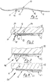
- Fig. 1 is a ski, especially touring skis, shown in a schematic side view and designated by the reference numeral 10.
- a tread 12 of conventional type is arranged, which defines a tread 11.
- a fur strip 13 is attached, in particular glued.
- This fur strip 13 serves as a repelling and / or climbing aid.
- the fur strip 13 is provided on the side facing the tread 11 with an adhesive layer, which is protected by a cover before use. This is subtracted, so that then the fur strip 13 can be glued to the tread 11.
- the fur strip 13 has a length which corresponds to about 30% of the total ski length. In principle, it is also conceivable to form the fur strip slightly longer, so that it extends over a greater length of the tread 11.
- the fur strip at the front end 14 includes a transition 15 between the tread 11 and fur or fur strip 13. Also, at the rear end 16 of the fur strip 13, such a transition between fur and tread may be provided.
- the front end of the fur strip 13 is covered by a plate 17 made of sheet metal, in particular stainless steel sheet, or plastic glued onto it, this plate 17 extending over the front edge 18 of the fur strip 13 towards the running surface 11.
- the plate 17 is bent over the front edge 18 of the fur strip 13 away convexly toward the tread 11, and indeed so far that it rests against the tread.
- This design ensures that when sliding over the snow on the plate 17, a higher pressure acts as the counter pressure, which builds up between plate 17 and tread 11 in the over the front edge 18 of the skin strip 13 projecting portion of the plate 17.
- the mentioned pressure is indicated by the arrow 19 and the mentioned back pressure with the arrow 20 in FIG Fig. 2 characterized. According to the pressure conditions, the arrow 19 is formed longer than the arrow 20th
- the plate 17, which is preferably formed by a stainless steel sheet, advantageously extends over the entire width of the tread 11 and over a length of about 10 to 50 mm, in particular about 20 to 40 mm.
- the plate 17 is adhered to the fur strip 13 with appropriate compression of the fur hair or fibers in this area, as in Fig. 2 is indicated.
- Fig. 3 an alternative Ausfahrungsform for a transition 15 according to the invention between tread 11 and fur 13 is shown.
- This transition is also plate-like and created by a fusion-compaction of the front end 14 of the fur strip 13.
- This melt compaction is in Fig. 3 indicated by the arrows 21.
- an artificial fur strip. 13 ie fur strips 13 of artificial material, such as polyamide, polyethylene od.
- the front end 14 of the thus formed skin strip 13 is compacted in a hot press.
- the generally rearwardly directed hair or fibers of the fur 13 melt and are fused to the base material of the fur strip 13 to form a transition plate which extends over the entire width of the tread 11 and over a length of 10 to 50 mm ,
- a transition 15 is shown, which is characterized in that the transition 15 obtained by melting of plastic 22 is again, again by forming a plate-like transition, wherein the plastic 22 extends beyond the front edge 18 of the fur strip 13 away. It is also conceivable that the transition from front to back increases slightly to almost the height of the hair or fiber tips of the coat 13.
- the fur strip 13 is an additional article which can be used as a repelling and / or climbing aid for a ski, in particular touring skis, and is glued to the middle area of the tread 12 or the tread 11 as required.
- the front and possibly also rear end of the fur strip 13 is designed as a relatively stiff, in particular plate-like transition 15 between ski running surface 11 and fur 13, said transition either according to Fig. 2 or according to Fig. 3 or according to Fig. 4 can be trained.
- the front transverse edge of the plate 17 rests against the tread 11.
- the risk of penetration of snow in the area between the plate 17 and tread 11 is even lower, so that such a concern is sought, especially under low elastic bias.
- the front edge of the plate 17 is in any case on the tread 11 under load, ie at loaded ski. But - as mentioned - it is quite advantageous if even with unloaded ski, the front transverse edge of the plate 17 rests against the tread 11.
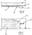
- FIGS. 5 and 6 only a part of a ski 10 is shown in a bottom view and side view, in such a way that the rear end 16 of a glued on the tread of the ski skin strip 13 can be seen.
- a finger loop 23 is fixed, which is made of a flat, preferably textile tape and passed through a corresponding eyelet at the rear end of the fur strip.
- the attachment of the finger loop 23 is preferably carried out so that the flat side of the loop band in the assembled state of the fur strip extends approximately parallel to this or to the tread 12 of the ski.
- a finger loop and a simple grip tab can be provided. With such aids, the rear end of the fur strip 13 can be very easily peeled off the tread 12, which is additionally facilitated when the rear
- End 16 of the fur strip 13 tapers in plan view and towards the ski end, as in Fig. 5 is indicated.
Landscapes
- Footwear And Its Accessory, Manufacturing Method And Apparatuses (AREA)
Description
- Die Erfindung betrifft einen Ski, insbesondere Touren- oder Langlaufski, mit einem auf die Lauffläche, insbesondere im mittleren Bereich derselben aufklebbaren Streifen aus natürlichem oder künstlichem Fell od. dgl. für eine Abstoß- und/oder Steighilfe wirksamem Material. Des weiteren betrifft die vorliegende Erfindung eine entsprechende Abstoß- und/oder Steighilfe.
- Ein Ski der eingangs genannten Art ist beispielsweise aus der
WO 2004/064949 A1 bekannt. Insbesondere zum Skiwandern werden Abstoß- oder Steighilfen in Form von sogenannten Fellen verwendet, die auf die Lauffläche des Ski geklebt werden. Es werden sowohl natürliche als auch künstliche, d.h. aus Kunstfasern bestehende Felle verwendet. Die Haare bzw. Fasern sind dabei so ausgerichtet, dass sie sich beim Rückstoß aufstellen und einen entsprechenden Widerstand bieten, so dass ein Tourengeher mit den Skiern einen Aufstieg problemlos bewältigen kann. Wie bereits erwähnt, lassen sich die bekannten Felle auf die Lauffläche eines Ski aufkleben. Alternativ werden die Felle über die Lauffläche gespannt, und zwar in der Regel über die gesamte Länge des Ski. Beim Aufkleben von Steigfellen besteht die Gefahr, dass die Klebewirkung im Laufe der Zeit nachläßt, und zwar aufgrund des Eindringens von Schnee und Feuchtigkeit zwischen Lauffläche und Fell, wobei sich Schnee vor allem am vorderen Ende des Fells ansammelt. Diese Ansammlung von Schnee nimmt bei jedem Gleitschritt zu mit der Folge, dass entsprechend zunehmend die Gefahr besteht, Schnee in den Klebbereich zwischen Lauffläche und Fell einzudrücken. Um dies zu vermeiden, wird in derWO 2004/064949 A1 vorgeschlagen, dem vorderen Ende des Steigfells eine Ausnehmung in der Lauffläche des Ski zuzuordnen, in die das vordere Ende des Steigfells hineinragt. Des weiteren ist in dieser Ausnehmung eine Platte eingeschraubt, und zwar so, dass der hintere nicht verschraubte Rand der Platte elastisch angehoben und aus der Ausnehmung heraus bewegt werden kann. Das vordere Ende des Fells kann dann zwischen der angehobenen Platte und dem Ski eingeklemmt werden, so dass das vordere Ende des Fells zusätzlich zur Klebewirkung mechanisch gesichert ist. Diese mechanische Fixierung ist technisch aufwendig und erfordert insbesondere auch eine Einwirkung auf den Laufbelag des Ski. Außerdem wird dadurch das Fahrverhalten des Ski negativ beeinflusst, da nach Entfernung des Fells die Klemmplatte samt Ausnehmung verbleiben, wodurch die Lauffläche gestört ist. - Der vorliegenden Erfindung liegt die Aufgabe zugrunde, einen Ski der eingangs genannten Art zu schaffen, der sich problemlos und dauerhaft funktionssicher mit einer fellartigen Abstoß- und/oder Steighilfe versehen lässt, die auch jederzeit problemlos wieder entfernt werden kann, ohne dass auf die Lauffläche eingewirkt wird. Des weiteren ist es Aufgabe der vorliegenden Erfindung, eine entsprechende Abstoß- und/oder Steighilfe zur Verfügung zu stellen, mit der bei Bedarf die Lauffläche eines Touren- oder Langlaufski versehen werden kann. Die Aufgabe der Erfindung wird mit einem Ski gemäß Anspruch 1 gelöst. Ein wesentlicher Grundgedanke der vorliegenden Erfindung besteht darin, dass wenigstens das vordere Ende des Fell- od. dgl. -Streifens einen relativ steifen Übergang zwischen Lauffläche und Fell umfasst. Dieser Übergang stellt sicher, dass kein Schnee zwischen Laufbelag und Fell gelangt, insbesondere nicht im vorderen Bereich des Fellstreifens. Der Grund dafür liegt darin, dass der beim Gleiten auf den Übergang einwirkende Druck größer ist als der innere Gegendruck, der sich zwischen dem Übergang und dem Laufbelag aufbauen konnte. Die äußere Druckfläche ist stets erheblich großer als die möglicherweise sich ausbildende innere Druckfläche. Damit ist gewährleistet, dass das vordere Ende des Fell- od. dgl. -Streifens stets in Anlage am Laufbelag gehalten bleibt.
- Gegebenenfalls kann auch das hintere Ende des Fell- od. dgl. -Streifens einen Übergang der vorgenannten. Art zwischen Fell und Lauffläche aufweisen, um auch am hinteren Ende ein Eindringen von Schnee in den Bereich der Klebfläche zu vermeiden. Insgesamt kann durch die erfindungsgemäße Maßnahme ein unerwünschtes Ablösen des Fell- od. dgl. -Streifens von der Lauffläche vermieden werden.
- Bevorzugte Ausführungsformen des erfindungsgemäßen Übergangs sind in den Ansprüchen 2 und 3 beschrieben. All diesen Ausführungsformen ist gemeinsam, dass der Übergang relativ steif und auch relativ glatt ausgebildet ist.
- Bei einer ersten Ausführungsform ist der Übergang zwischen Lauffläche und Fell plattenartig und entweder durch eine Schmelz-Kompaktierung des vorderen und gegebenenfalls auch des hinteren Endes des Fell- od. dgl. -Streifens, oder durch Aufschmelzung von Kunststoff geschaffen.
- Eine weitere Alternative zeichnet sich dadurch aus, dass das vordere und gegebenenfalls auch das hintere Ende des Fell- od. dgl. -Streifens durch eine auf diesen aufgeklebte Platte aus Metall oder Kunststoff abgedeckt ist, wobei diese Platte sich über die vordere und gegebenenfalls auch hintere Kante des Fell- od. dgl. -Streifens hinweg zur Lauffläche hin erstreckt, und zwar bis in unmittelbare Nahe der Lauffläche oder vorzugsweise in Anlage an diese.
- Bei einer vorteilhaften konkreten Ausführungsform ist die Metall- oder Kunststoffplatte über die vordere und gegebenenfalls auch hintere Kante des Fell- od. dgl. -Streifens hinweg konvex zur Lauffläche hin gebogen.
- Des weiteren ist es vorteilhaft, wenn sich der erwähnte Übergang am vorderen und gegebenenfalls auch hinteren Ende des Fell- od. dgl. -Streifens über dessen gesamte Breite und über eine Länge von 10 bis 50 mm, insbesondere etwa 20 bis 40 mm erstreckt.
- Weiterhin, ein Gleitschutz der genannten Art is aus
FR 810 162 A - Teil der vorliegenden Erfindung ist auch eine entsprechend ausgebildete Abstoß- und/oder Steighilfe für einen. Ski, insbesondere Tourenski, die in Form eines auf den Laufbelag des Ski, insbesondere im mittleren Bereich desselben aufklebbaren Streifens aus natürlichem oder künstlichem Fell ausgebildet ist, dessen vorderes und gegebenenfalls auch hinteres Ende einen relativ steifen, insbesondere plattenartigen Übergang zwischen Skilauffläche und Fell umfasst, wobei dieser Übergang vorzugsweise nach einen der vorgenannten Ausführungen gestaltet ist.
- Der erwähnte Übergang zwischen Lauffläche und Fell ist also Teil des Fells und wirkt als Schnee- und Feuchtigkeitsabweiser. Beim Gebrauch wird dieser Feuchtigkeitsabweiser gegen die Lauffläche gedrückt, wodurch sich eine wirkungsvolle Abdichtung am vorderen und gegebenenfalls auch hinteren Ende des Fells zwischen diesem und dem Laufbelag ergibt. Dadurch wird verhindert, dass Feuchtigkeit oder Schnee zwischen Fell und Lauffläche eindringt.
- Nachstehend werden Ausführungsbeispiele der Erfindung anhand der beigefugten Zeichnung näher erläutert. Diese zeigt in:
-
Fig. 1 einen Ski mit im mittleren Bereich der Lauffläche aufgeklebtem Fell gemäß Erfindung in schematischer Seitenansicht; -
Fig. 2 den vorderen Teil eines ersten Ausführungsbeispiels eines erfindungsgemäß ausgebildeten Fellstreifens an der Unterseite eines Ski-Laufbelags in vergrößertem Maßstab und Längsschnitt; -
Fig. 3 den vorderen Teil eines zweiten Ausführungsbeispiels eines erfindungsgemäß ausgebildeten Fellstreifens an der Unterseite eines Ski-Laufbelags in vergrößertem Maßstab und Längsschnitt; -
Fig. 4 den vorderen Teil eines dritten Ausführungsbeispiels eines erfindungsgemäß ausgebildeten Fellstreifens an der Unterseite eines Ski-Laufbelags in vergrößertem Maßstab und Längsschnitt; und -
Fig. 5 u. 6 das hintere Ende des Fellstreifens mit Fingerschlaufe zur Entfernung des Fellstreifens vom Laufbelag in Drauf- und Seitenansicht. - In
Fig. 1 ist ein Ski, insbesondere Tourenski, in schematischer Seitenansicht dargestellt und mit der Bezugsziffer 10 gekennzeichnet. An der Unterseite des Ski 10 ist ein Laufbelag 12 herkömmlicher Art angeordnet, der eine Lauffläche 11 definiert. Im mittleren Bereich der Lauffläche 11 ist ein Fellstreifen 13 befestigt, insbesondere aufgeklebt. Dieser Fellstreifen 13 dient als Abstoß- und/oder Steighilfe. Der Fellstreifen 13 ist an der der Lauffläche 11 zugekehrten Seite mit einer Klebschicht versehen, die vor dem Gebrauch durch eine Abdeckfolie geschützt ist. Diese wird abgezogen, so dass dann der Fellstreifen 13 auf die Lauffläche 11 geklebt werden kann. Wird der Fellstreifen 13 von der Lauffläche 11 wieder abgezogen, wird die Klebschicht des Fellstreifens 13 wieder mit der erwähnten Abdeckfolie abgedeckt, so dass der Fellstreifen aufgerollt und verstaut werden kann, ohne dass eine Wiederverwendung durch die Klebschicht verhindert oder beeinträchtigt ist. Der Fellstreifen 13 weist eine Länge auf, die etwa 30 % der gesamten Ski-länge entspricht. Grundsätzlich ist es auch denkbar, den Fellstreifen etwas Länger auszubilden, so dass er sich über eine größere Länge der Lauffläche 11 erstreckt. - Von besonderer Bedeutung ist, dass der Fellstreifen am vorderen Ende 14 einen Übergang 15 zwischen Lauffläche 11 und Fell bzw. Fellstreifen 13 umfasst. Auch am hinteren Ende 16 des Fellstreifens 13 kann ein solcher Übergang zwischen Fell und Lauffläche vorgesehen sein.
- Bei der Ausführungsform gemäß
Fig. 2 ist das vordere Ende des Fellstreifens 13 durch eine auf diesen aufgeklebte Platte 17 aus Metallblech, insbesondere Edelstahlblech, oder Kunststoff abgedeckt, wobei diese Platte 17 sich über die vordere Kante 18 des Fellstreifens 13 hinweg zur Lauffläche 11 hin erstreckt. Konkret ist die Platte 17 Uber die vordere Kante 18 des Fellstreifens 13 hinweg konvex zur Lauffläche 11 hin gebogen, und zwar so weit, dass sie an der Lauffläche anliegt. Durch diese Konzeption wird erreicht, dass beim Gleiten über den Schnee auf die Platte 17 ein höherer Druck wirkt als der Gegendruck, der sich zwischen Platte 17 und Lauffläche 11 in dem über die vordere Kante 18 des Fellstreifens 13 vorstehenden Bereich der Platte 17 aufbaut. Der erwähnte Druck ist mit dem Pfeil 19 und der erwähnte Gegendruck mit dem Pfeil 20 inFig. 2 gekennzeichnet. Entsprechend den Druckverhältnissen ist der Pfeil 19 länger ausgebildet als der Pfeil 20. - Die Platte 17, die vorzugsweise durch ein Edelstahlblech gebildet ist, erstreckt sich vorteilhafterweise über die gesamte Breite der Lauffläche 11 und über eine Länge von etwa 10 bis 50 mm, insbesondere etwa 20 bis 40 mm. Die Platte 17 ist auf den Fellstreifen 13 aufgeklebt unter entsprechender Komprimierung der Fellhaare bzw. -fasern in diesem Bereich, so wie dies in
Fig. 2 angedeutet ist. - In
Fig. 3 ist eine alternative Ausfahrungsform für einen erfindungsgemäßen Übergang 15 zwischen Lauffläche 11 und Fell 13 dargestellt. Dieser Übergang ist ebenfalls plattenartig ausgebildet und durch eine Schmelz-Kompaktierung des vorderen Endes 14 des Fellstreifens 13 geschaffen. Diese Schmelz-Kompaktierung ist inFig. 3 mit den Pfeilen 21 angedeutet. Natürlich geht dies nur bei einem künstlichen Fellstreifen. 13, d.h. Fellstreifen 13 aus künstlichem Material, wie Polyamid, Polyethylen od. dgl. Das vordere Ende 14 des so ausgebildeten Fellstreifens 13 wird in einer Heißpresse kompaktiert. Dabei schmelzen die in der Regel nach hinten gerichteten Haare bzw. Fasern des Fells 13 auf und werden mit dem Basismaterial des Fellstreifens 13 verschmolzen unter Ausbildung einer Übergangsplatte, die sich über die gesamte Breite der Lauffläche 11 und über eine Länge von 10 bis 50 mm erstreckt. - In
Fig. 4 ist noch eine alternative Ausführungsform für einen Übergang 15 dargestellt, die dadurch gekennzeichnet ist, dass der Übergang 15 durch Aufschmelzung von Kunststoff 22 erhalten wird, und zwar ebenfalls wieder durch Ausbildung eines plattenartigen Übergangs, wobei sich der Kunststoff 22 über die vordere Kante 18 des Fellstreifens 13 hinweg erstreckt. Auch ist es denkbar, dass der Übergang von vorne nach hinten leicht ansteigt bis nahezu auf Hohe der Haar- bzw. Faserspitzen des Fells 13. - Wie bereits erwähnt, handelt es sich bei dem Fellstreifen 13 um einen Zusatzartikel, der als Abstoß- und/oder Steighilfe für einen Ski, insbesondere Tourenski verwendbar ist und bei Bedarf auf den mittleren Bereich des Laufbelages 12 bzw. der Lauffläche 11 aufgeklebt wird. Das vordere und gegebenenfalls auch hintere Ende des Fellstreifens 13 ist als relativ steifer, insbesondere plattenartiger Übergang 15 zwischen Skilauffläche 11 und Fell 13 gestaltet, wobei dieser Übergang entweder gemäß
Fig. 2 oder gemäßFig. 3 oder gemäßFig. 4 ausgebildet sein kann. - Aufgrund der anhand der
Fig. 2 dargestellten Druckverhältnisse ist es nicht unbedingt erforderlich, dass die vordere Querkante der Platte 17 an der Lauffläche 11 anliegt. Andererseits ist dann jedoch die Gefahr eines Eindringens von Schnee in den Bereich zwischen Platte 17 und Lauffläche 11 noch geringer, so dass ein solches Anliegen angestrebt ist, insbesondere unter geringer elastischer Vorspannung. Natürlich liegt die Vorderkante der Platte 17 auf jeden Fall an der Lauffläche 11 unter Belastung an, d.h. bei belastetem Ski. Doch - wie erwähnt - ist es durchaus vorteilhaft, wenn auch bei unbelastetem Ski die vordere Querkante der Platte 17 an der Lauffläche 11 anliegt. - Die vorgenannten Druckverhältnisse gelten natürlich auch für die Ausführungsformen gemäß den
Figuren. 3 und 4 . - In den
Fig. 5 und 6 ist nur ein Teil eines Ski 10 in Unteransicht sowie Seitenansicht dargestellt, und zwar so, dass das hintere Ende 16 eines auf die Lauffläche des Ski aufgeklebten Fellstreifens 13 erkennbar ist. An diesem hinteren Ende 16 des Fellstreifens ist eine Fingerschlaufe 23 befestigt, die aus einem flachen, vorzugsweise textilen Band hergestellt und durch eine entsprechende Öse am hinteren Ende des Fellstreifens hindurchgeführt ist. Alternativ ist auch eine andere Art der Befestigung der Fingerschlaufe 23, z. B. Verklebung mit dem Fellstreifen 13 denkbar. Die Befestigung der Fingerschlaufe 23 erfolgt vorzugsweise so, dass die Flachseite des Schlaufenbandes im montierten Zustand des Fellstreifens sich etwa parallel zu diesem bzw. zum Laufbelag 12 des Ski erstreckt. Statt einer Fingerschlaufe kann auch eine einfache Grifflasche vorgesehen sein. Mit solchen Hilfsmitteln lässt sich das hintere Ende des Fellstreifens 13 von der Lauffläche bzw. dem Laufbelag 12 sehr leicht abziehen, wobei dies zusätzlich erleichtert wird, wenn das hintere - Ende 16 des Fellstreifens 13 sich in Draufsicht und in Richtung zum Skiende hin verjüngt, so wie dies in
Fig. 5 angedeutet ist. -
- 10
- Ski
- 11
- Lauffläche
- 12
- Laufbelag
- 13
- Fellstreifen
- 14
- vorderes Ende
- 15
- Übergang
- 16
- hinteres Ende
- 17
- Platte
- 18
- vordere Kante
- 19
- Schneedruck
- 20
- innerer Gegendruck
- 21
- Schmelz-Kompaktierung
- 22
- Kunststoff-Aufschmelzung
- 23
- Grifflasche bzw. Fingerschlaufe
Claims (3)
- Ski, insbesondere Touren- oder Langlaufski (10), mit einem auf die Lauffläche (11), insbesondere im mittleren Bereich derselben aufklebbaren Streifen (13) aus natürlichem oder künstlichem Fell, wobei dass wenigstens das vordere Ende (14) des Fellstreifens (13) einen Übergang (15) zwischen Lauffläche (11) und Fell (13) umfasst, und gegebenenfalls auch das hintere Ende (16) des Fellstreifens (13) einen Übergang zwischen Fell und Lauffläche aufweist, dadurch gekennzeichnet, dass der Übergang (15) zwischen Lauffläche (11) und Fell (13) plattenartig ausgebildet ist und entweder durch eine Schmelz-Kompaktierung (21) des vorderen (14) und gegebenenfalls auch des hinteren (16) Endes des Fellstreifens (13), oder durch Aufschmelzung von Kunststoff (22) geschaffen ist, wobei das vordere (14) und gegebenenfalls auch das hintere (16) Ende des Fellstreifens (13) durch eine aufgeklebte Platte (17) aus Metall oder Kunststoff abgedeckt ist, wobei diese Platte (17) sich über die vordere (18) und gegebenenfalls auch hintere Kante des Fellstreifens (13) hinweg zur Lauffläche (11) hin erstreckt.
- Ski nach Anspruch 1, dadurch gekennzeichnet, dass die Metall- oder Kunststoffplatte (17) über die vordere (18) und gegebenenfalls auch hintere Kante des Fellstreifens (13) hinweg konvex zur Lauffläche (11) hin gebogen ist und vorzugsweise mit ihrer vorderen Querkante an dieser anliegt.
- Ski nach Anspruch 2, dadurch gekennzeichnet, dass die Platte (17) im Bereich des freien Endes einen größeren Krümmungsradius als im übrigen Bereich aufweist.
Applications Claiming Priority (3)
| Application Number | Priority Date | Filing Date | Title |
|---|---|---|---|
| DE200520010571 DE202005010571U1 (de) | 2005-07-05 | 2005-07-05 | Ski, insbesondere Langlaufski, und Fellstreifen für einen Ski |
| DE200520013673 DE202005013673U1 (de) | 2005-08-30 | 2005-08-30 | Ski, insbesondere Touren- oder Langlaufski, und Abstoß und/oder Steighilfe dafür |
| PCT/IB2006/001831 WO2007004034A1 (de) | 2005-07-05 | 2006-07-03 | Ski, insbesondere touren- oder langlaufski, und abstoss- und/oder steighilfe dafür |
Publications (2)
| Publication Number | Publication Date |
|---|---|
| EP1907077A1 EP1907077A1 (de) | 2008-04-09 |
| EP1907077B1 true EP1907077B1 (de) | 2017-11-01 |
Family
ID=37101664
Family Applications (1)
| Application Number | Title | Priority Date | Filing Date |
|---|---|---|---|
| EP06795070.9A Not-in-force EP1907077B1 (de) | 2005-07-05 | 2006-07-03 | Ski, insbesondere touren- oder langlaufski, und abstoss- und/oder steighilfe dafür |
Country Status (2)
| Country | Link |
|---|---|
| EP (1) | EP1907077B1 (de) |
| WO (1) | WO2007004034A1 (de) |
Families Citing this family (2)
| Publication number | Priority date | Publication date | Assignee | Title |
|---|---|---|---|---|
| WO2008122061A1 (de) * | 2007-04-06 | 2008-10-16 | Michael Puelacher | Schifell |
| EP2745886A1 (de) | 2012-12-21 | 2014-06-25 | ATOMIC Austria GmbH | Schi oder Snowboard mit einem Mittel zur Beeinflussung seiner Geometrie sowie Verfahren zu dessen Herstellung |
Family Cites Families (4)
| Publication number | Priority date | Publication date | Assignee | Title |
|---|---|---|---|---|
| DE654487C (de) * | 1935-08-28 | 1937-12-20 | Walter Hummel | Gleitschutz fuer Skier |
| FR2234909A1 (en) * | 1973-06-27 | 1975-01-24 | Dieupart Pierre | Method of retaining anti skid strips under skis - front of strip is held firmly in rebate between plastic surface and ski |
| EP1329245B1 (de) * | 2002-01-22 | 2006-07-19 | Tödi Sport AG | Ski mit einer Vorrichtung zur Befestigung eines Skifells |
| NO318691B1 (no) * | 2003-01-24 | 2005-04-25 | Erik Hartmann | Frasparkfremmende anordning for ski |
-
2006
- 2006-07-03 EP EP06795070.9A patent/EP1907077B1/de not_active Not-in-force
- 2006-07-03 WO PCT/IB2006/001831 patent/WO2007004034A1/de not_active Ceased
Non-Patent Citations (1)
| Title |
|---|
| None * |
Also Published As
| Publication number | Publication date |
|---|---|
| EP1907077A1 (de) | 2008-04-09 |
| WO2007004034A1 (de) | 2007-01-11 |
Similar Documents
| Publication | Publication Date | Title |
|---|---|---|
| DE3310739C2 (de) | ||
| DE3417503A1 (de) | Ski-schuh | |
| DE3418604C2 (de) | ||
| DE7341859U (de) | Bremse für Skier | |
| DE69502033T2 (de) | Ski mit "in situ" injiziertem Kern | |
| DE2142678A1 (de) | Gleitplatte zwischen skistiefelsohle und skioberflaeche bei ausloesenden skibindungen | |
| EP1726338A1 (de) | Befestigungsvorrichtung für ein Skifell und Ski mit einem solchen Skifell | |
| DE3115618A1 (de) | Halterungsgesamtheit eines langlaufskischuhes auf einem ski | |
| DE3929352A1 (de) | Seitliche fuehrungsvorrichtung eines skischuhs | |
| DE2600899A1 (de) | Skisicherheitsbindung | |
| DE3040253A1 (de) | Vorrichtung zum beeinflussen des bodenkontaktes an skiern, insbesondere langlaufskiern | |
| DE3334488A1 (de) | Vorrichtung zum verhindern des zurueckgleitens eines skis | |
| WO2007004034A1 (de) | Ski, insbesondere touren- oder langlaufski, und abstoss- und/oder steighilfe dafür | |
| DE2615196A1 (de) | Langlaufski | |
| DE202005013673U1 (de) | Ski, insbesondere Touren- oder Langlaufski, und Abstoß und/oder Steighilfe dafür | |
| DE4040383A1 (de) | Alpine sicherheitsskibindung | |
| EP2727635A1 (de) | Steighilfe für Schneesportgeräte und Reparaturelement | |
| CH653561A5 (de) | Sicherheitsskibindung. | |
| CH700590B1 (de) | Skihaftfell. | |
| DE202007013692U1 (de) | Pferdehufschuh | |
| EP2206538B1 (de) | Ski | |
| EP3250298B1 (de) | Ski mit steighilfe | |
| CH672601A5 (de) | ||
| DE202005010571U1 (de) | Ski, insbesondere Langlaufski, und Fellstreifen für einen Ski | |
| AT352601B (de) | Langlaufschibindung |
Legal Events
| Date | Code | Title | Description |
|---|---|---|---|
| PUAI | Public reference made under article 153(3) epc to a published international application that has entered the european phase |
Free format text: ORIGINAL CODE: 0009012 |
|
| 17P | Request for examination filed |
Effective date: 20071227 |
|
| AK | Designated contracting states |
Kind code of ref document: A1 Designated state(s): AT BE BG CH CY CZ DE DK EE ES FI FR GB GR HU IE IS IT LI LT LU LV MC NL PL PT RO SE SI SK TR |
|
| RIN1 | Information on inventor provided before grant (corrected) |
Inventor name: HAUGLIN, BERNT-OTTO Inventor name: HARTMANN, ERIK |
|
| RAP1 | Party data changed (applicant data changed or rights of an application transferred) |
Owner name: HARTMANN, ERIK |
|
| DAX | Request for extension of the european patent (deleted) | ||
| 17Q | First examination report despatched |
Effective date: 20151029 |
|
| GRAP | Despatch of communication of intention to grant a patent |
Free format text: ORIGINAL CODE: EPIDOSNIGR1 |
|
| INTG | Intention to grant announced |
Effective date: 20170313 |
|
| GRAS | Grant fee paid |
Free format text: ORIGINAL CODE: EPIDOSNIGR3 |
|
| RIN1 | Information on inventor provided before grant (corrected) |
Inventor name: HARTMANN, ERIK Inventor name: HAUGLIN, BERNT-OTTO |
|
| GRAA | (expected) grant |
Free format text: ORIGINAL CODE: 0009210 |
|
| RAP1 | Party data changed (applicant data changed or rights of an application transferred) |
Owner name: ACTIVE BRANDS AS |
|
| AK | Designated contracting states |
Kind code of ref document: B1 Designated state(s): AT BE BG CH CY CZ DE DK EE ES FI FR GB GR HU IE IS IT LI LT LU LV MC NL PL PT RO SE SI SK TR |
|
| REG | Reference to a national code |
Ref country code: GB Ref legal event code: FG4D Free format text: NOT ENGLISH |
|
| REG | Reference to a national code |
Ref country code: CH Ref legal event code: EP Ref country code: AT Ref legal event code: REF Ref document number: 941479 Country of ref document: AT Kind code of ref document: T Effective date: 20171115 |
|
| REG | Reference to a national code |
Ref country code: IE Ref legal event code: FG4D Free format text: LANGUAGE OF EP DOCUMENT: GERMAN |
|
| REG | Reference to a national code |
Ref country code: DE Ref legal event code: R096 Ref document number: 502006015715 Country of ref document: DE |
|
| REG | Reference to a national code |
Ref country code: CH Ref legal event code: NV Representative=s name: RENTSCH PARTNER AG, CH |
|
| REG | Reference to a national code |
Ref country code: SE Ref legal event code: TRGR |
|
| REG | Reference to a national code |
Ref country code: NL Ref legal event code: MP Effective date: 20171101 |
|
| REG | Reference to a national code |
Ref country code: LT Ref legal event code: MG4D |
|
| PG25 | Lapsed in a contracting state [announced via postgrant information from national office to epo] |
Ref country code: FI Free format text: LAPSE BECAUSE OF FAILURE TO SUBMIT A TRANSLATION OF THE DESCRIPTION OR TO PAY THE FEE WITHIN THE PRESCRIBED TIME-LIMIT Effective date: 20171101 Ref country code: NL Free format text: LAPSE BECAUSE OF FAILURE TO SUBMIT A TRANSLATION OF THE DESCRIPTION OR TO PAY THE FEE WITHIN THE PRESCRIBED TIME-LIMIT Effective date: 20171101 Ref country code: ES Free format text: LAPSE BECAUSE OF FAILURE TO SUBMIT A TRANSLATION OF THE DESCRIPTION OR TO PAY THE FEE WITHIN THE PRESCRIBED TIME-LIMIT Effective date: 20171101 Ref country code: LT Free format text: LAPSE BECAUSE OF FAILURE TO SUBMIT A TRANSLATION OF THE DESCRIPTION OR TO PAY THE FEE WITHIN THE PRESCRIBED TIME-LIMIT Effective date: 20171101 |
|
| PG25 | Lapsed in a contracting state [announced via postgrant information from national office to epo] |
Ref country code: GR Free format text: LAPSE BECAUSE OF FAILURE TO SUBMIT A TRANSLATION OF THE DESCRIPTION OR TO PAY THE FEE WITHIN THE PRESCRIBED TIME-LIMIT Effective date: 20180202 Ref country code: LV Free format text: LAPSE BECAUSE OF FAILURE TO SUBMIT A TRANSLATION OF THE DESCRIPTION OR TO PAY THE FEE WITHIN THE PRESCRIBED TIME-LIMIT Effective date: 20171101 Ref country code: BG Free format text: LAPSE BECAUSE OF FAILURE TO SUBMIT A TRANSLATION OF THE DESCRIPTION OR TO PAY THE FEE WITHIN THE PRESCRIBED TIME-LIMIT Effective date: 20180201 Ref country code: IS Free format text: LAPSE BECAUSE OF FAILURE TO SUBMIT A TRANSLATION OF THE DESCRIPTION OR TO PAY THE FEE WITHIN THE PRESCRIBED TIME-LIMIT Effective date: 20180301 |
|
| REG | Reference to a national code |
Ref country code: FR Ref legal event code: PLFP Year of fee payment: 13 |
|
| PG25 | Lapsed in a contracting state [announced via postgrant information from national office to epo] |
Ref country code: DK Free format text: LAPSE BECAUSE OF FAILURE TO SUBMIT A TRANSLATION OF THE DESCRIPTION OR TO PAY THE FEE WITHIN THE PRESCRIBED TIME-LIMIT Effective date: 20171101 Ref country code: SK Free format text: LAPSE BECAUSE OF FAILURE TO SUBMIT A TRANSLATION OF THE DESCRIPTION OR TO PAY THE FEE WITHIN THE PRESCRIBED TIME-LIMIT Effective date: 20171101 Ref country code: CZ Free format text: LAPSE BECAUSE OF FAILURE TO SUBMIT A TRANSLATION OF THE DESCRIPTION OR TO PAY THE FEE WITHIN THE PRESCRIBED TIME-LIMIT Effective date: 20171101 Ref country code: CY Free format text: LAPSE BECAUSE OF FAILURE TO SUBMIT A TRANSLATION OF THE DESCRIPTION OR TO PAY THE FEE WITHIN THE PRESCRIBED TIME-LIMIT Effective date: 20171101 Ref country code: EE Free format text: LAPSE BECAUSE OF FAILURE TO SUBMIT A TRANSLATION OF THE DESCRIPTION OR TO PAY THE FEE WITHIN THE PRESCRIBED TIME-LIMIT Effective date: 20171101 |
|
| REG | Reference to a national code |
Ref country code: DE Ref legal event code: R097 Ref document number: 502006015715 Country of ref document: DE |
|
| PG25 | Lapsed in a contracting state [announced via postgrant information from national office to epo] |
Ref country code: PL Free format text: LAPSE BECAUSE OF FAILURE TO SUBMIT A TRANSLATION OF THE DESCRIPTION OR TO PAY THE FEE WITHIN THE PRESCRIBED TIME-LIMIT Effective date: 20171101 Ref country code: IT Free format text: LAPSE BECAUSE OF FAILURE TO SUBMIT A TRANSLATION OF THE DESCRIPTION OR TO PAY THE FEE WITHIN THE PRESCRIBED TIME-LIMIT Effective date: 20171101 Ref country code: RO Free format text: LAPSE BECAUSE OF FAILURE TO SUBMIT A TRANSLATION OF THE DESCRIPTION OR TO PAY THE FEE WITHIN THE PRESCRIBED TIME-LIMIT Effective date: 20171101 |
|
| PLBE | No opposition filed within time limit |
Free format text: ORIGINAL CODE: 0009261 |
|
| STAA | Information on the status of an ep patent application or granted ep patent |
Free format text: STATUS: NO OPPOSITION FILED WITHIN TIME LIMIT |
|
| 26N | No opposition filed |
Effective date: 20180802 |
|
| PG25 | Lapsed in a contracting state [announced via postgrant information from national office to epo] |
Ref country code: SI Free format text: LAPSE BECAUSE OF FAILURE TO SUBMIT A TRANSLATION OF THE DESCRIPTION OR TO PAY THE FEE WITHIN THE PRESCRIBED TIME-LIMIT Effective date: 20171101 |
|
| REG | Reference to a national code |
Ref country code: DE Ref legal event code: R119 Ref document number: 502006015715 Country of ref document: DE |
|
| GBPC | Gb: european patent ceased through non-payment of renewal fee |
Effective date: 20180703 |
|
| PG25 | Lapsed in a contracting state [announced via postgrant information from national office to epo] |
Ref country code: MC Free format text: LAPSE BECAUSE OF FAILURE TO SUBMIT A TRANSLATION OF THE DESCRIPTION OR TO PAY THE FEE WITHIN THE PRESCRIBED TIME-LIMIT Effective date: 20171101 Ref country code: LU Free format text: LAPSE BECAUSE OF NON-PAYMENT OF DUE FEES Effective date: 20180703 |
|
| REG | Reference to a national code |
Ref country code: BE Ref legal event code: MM Effective date: 20180731 |
|
| REG | Reference to a national code |
Ref country code: IE Ref legal event code: MM4A |
|
| PG25 | Lapsed in a contracting state [announced via postgrant information from national office to epo] |
Ref country code: IE Free format text: LAPSE BECAUSE OF NON-PAYMENT OF DUE FEES Effective date: 20180703 Ref country code: DE Free format text: LAPSE BECAUSE OF NON-PAYMENT OF DUE FEES Effective date: 20190201 Ref country code: GB Free format text: LAPSE BECAUSE OF NON-PAYMENT OF DUE FEES Effective date: 20180703 |
|
| PG25 | Lapsed in a contracting state [announced via postgrant information from national office to epo] |
Ref country code: BE Free format text: LAPSE BECAUSE OF NON-PAYMENT OF DUE FEES Effective date: 20180731 |
|
| REG | Reference to a national code |
Ref country code: AT Ref legal event code: MM01 Ref document number: 941479 Country of ref document: AT Kind code of ref document: T Effective date: 20180703 |
|
| PGFP | Annual fee paid to national office [announced via postgrant information from national office to epo] |
Ref country code: SE Payment date: 20190719 Year of fee payment: 14 Ref country code: FR Payment date: 20190719 Year of fee payment: 14 |
|
| PG25 | Lapsed in a contracting state [announced via postgrant information from national office to epo] |
Ref country code: AT Free format text: LAPSE BECAUSE OF NON-PAYMENT OF DUE FEES Effective date: 20180703 |
|
| PGFP | Annual fee paid to national office [announced via postgrant information from national office to epo] |
Ref country code: CH Payment date: 20190719 Year of fee payment: 14 |
|
| PG25 | Lapsed in a contracting state [announced via postgrant information from national office to epo] |
Ref country code: TR Free format text: LAPSE BECAUSE OF FAILURE TO SUBMIT A TRANSLATION OF THE DESCRIPTION OR TO PAY THE FEE WITHIN THE PRESCRIBED TIME-LIMIT Effective date: 20171101 |
|
| PG25 | Lapsed in a contracting state [announced via postgrant information from national office to epo] |
Ref country code: HU Free format text: LAPSE BECAUSE OF FAILURE TO SUBMIT A TRANSLATION OF THE DESCRIPTION OR TO PAY THE FEE WITHIN THE PRESCRIBED TIME-LIMIT; INVALID AB INITIO Effective date: 20060703 Ref country code: PT Free format text: LAPSE BECAUSE OF FAILURE TO SUBMIT A TRANSLATION OF THE DESCRIPTION OR TO PAY THE FEE WITHIN THE PRESCRIBED TIME-LIMIT Effective date: 20171101 |
|
| REG | Reference to a national code |
Ref country code: CH Ref legal event code: PL |
|
| REG | Reference to a national code |
Ref country code: SE Ref legal event code: EUG |
|
| PG25 | Lapsed in a contracting state [announced via postgrant information from national office to epo] |
Ref country code: LI Free format text: LAPSE BECAUSE OF NON-PAYMENT OF DUE FEES Effective date: 20200731 Ref country code: CH Free format text: LAPSE BECAUSE OF NON-PAYMENT OF DUE FEES Effective date: 20200731 Ref country code: FR Free format text: LAPSE BECAUSE OF NON-PAYMENT OF DUE FEES Effective date: 20200731 |
|
| PG25 | Lapsed in a contracting state [announced via postgrant information from national office to epo] |
Ref country code: SE Free format text: LAPSE BECAUSE OF NON-PAYMENT OF DUE FEES Effective date: 20200704 |