EP1903230B2 - Wälzlagervorrichtung - Google Patents
Wälzlagervorrichtung Download PDFInfo
- Publication number
- EP1903230B2 EP1903230B2 EP07018746A EP07018746A EP1903230B2 EP 1903230 B2 EP1903230 B2 EP 1903230B2 EP 07018746 A EP07018746 A EP 07018746A EP 07018746 A EP07018746 A EP 07018746A EP 1903230 B2 EP1903230 B2 EP 1903230B2
- Authority
- EP
- European Patent Office
- Prior art keywords
- inner ring
- peripheral surface
- rolling bearing
- bearing apparatus
- conical
- Prior art date
- Legal status (The legal status is an assumption and is not a legal conclusion. Google has not performed a legal analysis and makes no representation as to the accuracy of the status listed.)
- Expired - Fee Related
Links
Images


Classifications
-
- F—MECHANICAL ENGINEERING; LIGHTING; HEATING; WEAPONS; BLASTING
- F16—ENGINEERING ELEMENTS AND UNITS; GENERAL MEASURES FOR PRODUCING AND MAINTAINING EFFECTIVE FUNCTIONING OF MACHINES OR INSTALLATIONS; THERMAL INSULATION IN GENERAL
- F16C—SHAFTS; FLEXIBLE SHAFTS; ELEMENTS OR CRANKSHAFT MECHANISMS; ROTARY BODIES OTHER THAN GEARING ELEMENTS; BEARINGS
- F16C33/00—Parts of bearings; Special methods for making bearings or parts thereof
- F16C33/30—Parts of ball or roller bearings
- F16C33/38—Ball cages
- F16C33/3837—Massive or moulded cages having cage pockets surrounding the balls, e.g. machined window cages
- F16C33/3843—Massive or moulded cages having cage pockets surrounding the balls, e.g. machined window cages formed as one-piece cages, i.e. monoblock cages
-
- F—MECHANICAL ENGINEERING; LIGHTING; HEATING; WEAPONS; BLASTING
- F16—ENGINEERING ELEMENTS AND UNITS; GENERAL MEASURES FOR PRODUCING AND MAINTAINING EFFECTIVE FUNCTIONING OF MACHINES OR INSTALLATIONS; THERMAL INSULATION IN GENERAL
- F16C—SHAFTS; FLEXIBLE SHAFTS; ELEMENTS OR CRANKSHAFT MECHANISMS; ROTARY BODIES OTHER THAN GEARING ELEMENTS; BEARINGS
- F16C19/00—Bearings with rolling contact, for exclusively rotary movement
- F16C19/02—Bearings with rolling contact, for exclusively rotary movement with bearing balls essentially of the same size in one or more circular rows
- F16C19/14—Bearings with rolling contact, for exclusively rotary movement with bearing balls essentially of the same size in one or more circular rows for both radial and axial load
- F16C19/16—Bearings with rolling contact, for exclusively rotary movement with bearing balls essentially of the same size in one or more circular rows for both radial and axial load with a single row of balls
- F16C19/163—Bearings with rolling contact, for exclusively rotary movement with bearing balls essentially of the same size in one or more circular rows for both radial and axial load with a single row of balls with angular contact
-
- F—MECHANICAL ENGINEERING; LIGHTING; HEATING; WEAPONS; BLASTING
- F16—ENGINEERING ELEMENTS AND UNITS; GENERAL MEASURES FOR PRODUCING AND MAINTAINING EFFECTIVE FUNCTIONING OF MACHINES OR INSTALLATIONS; THERMAL INSULATION IN GENERAL
- F16C—SHAFTS; FLEXIBLE SHAFTS; ELEMENTS OR CRANKSHAFT MECHANISMS; ROTARY BODIES OTHER THAN GEARING ELEMENTS; BEARINGS
- F16C33/00—Parts of bearings; Special methods for making bearings or parts thereof
- F16C33/30—Parts of ball or roller bearings
- F16C33/66—Special parts or details in view of lubrication
- F16C33/6637—Special parts or details in view of lubrication with liquid lubricant
- F16C33/6681—Details of distribution or circulation inside the bearing, e.g. grooves on the cage or passages in the rolling elements
-
- F—MECHANICAL ENGINEERING; LIGHTING; HEATING; WEAPONS; BLASTING
- F16—ENGINEERING ELEMENTS AND UNITS; GENERAL MEASURES FOR PRODUCING AND MAINTAINING EFFECTIVE FUNCTIONING OF MACHINES OR INSTALLATIONS; THERMAL INSULATION IN GENERAL
- F16C—SHAFTS; FLEXIBLE SHAFTS; ELEMENTS OR CRANKSHAFT MECHANISMS; ROTARY BODIES OTHER THAN GEARING ELEMENTS; BEARINGS
- F16C2322/00—Apparatus used in shaping articles
- F16C2322/39—General build up of machine tools, e.g. spindles, slides, actuators
-
- F—MECHANICAL ENGINEERING; LIGHTING; HEATING; WEAPONS; BLASTING
- F16—ENGINEERING ELEMENTS AND UNITS; GENERAL MEASURES FOR PRODUCING AND MAINTAINING EFFECTIVE FUNCTIONING OF MACHINES OR INSTALLATIONS; THERMAL INSULATION IN GENERAL
- F16C—SHAFTS; FLEXIBLE SHAFTS; ELEMENTS OR CRANKSHAFT MECHANISMS; ROTARY BODIES OTHER THAN GEARING ELEMENTS; BEARINGS
- F16C2360/00—Engines or pumps
- F16C2360/44—Centrifugal pumps
- F16C2360/45—Turbo-molecular pumps
-
- F—MECHANICAL ENGINEERING; LIGHTING; HEATING; WEAPONS; BLASTING
- F16—ENGINEERING ELEMENTS AND UNITS; GENERAL MEASURES FOR PRODUCING AND MAINTAINING EFFECTIVE FUNCTIONING OF MACHINES OR INSTALLATIONS; THERMAL INSULATION IN GENERAL
- F16C—SHAFTS; FLEXIBLE SHAFTS; ELEMENTS OR CRANKSHAFT MECHANISMS; ROTARY BODIES OTHER THAN GEARING ELEMENTS; BEARINGS
- F16C33/00—Parts of bearings; Special methods for making bearings or parts thereof
- F16C33/30—Parts of ball or roller bearings
- F16C33/58—Raceways; Race rings
- F16C33/583—Details of specific parts of races
Definitions
- This invention relates to a rolling bearing apparatus, and more particularly to a rolling bearing apparatus suited for use in a machine tool (such as a high-speed rotation spindle) and a turbo-molecular pump.
- This lubricant supplying structure includes a rotor (rotating member) capable of rotating at high speed, and an oil reservoir, and the rotor has a distal end portion of a conical shape.
- the distal end portion of the rotor extends generally parallel to a vertical direction in such a manner that a larger-diameter-side portion of the distal end portion is located at the upper side in the vertical direction, while a smaller-diameter-side portion of the distal end portion is immersed in lubricant held in the oil reservoir.
- JP 2002 161922 discloses a roller bearing according to the preamble part of claim 1.
- a larger-diameter end of the conical outer peripheral surface is connected to the end surface of the inner ring with no clearance formed therebetween (or with substantially no clearance formed therebetween), and also the outer ring projects axially outwardly of the end surface of the inner ring.
- this lubricant of a minute amount can be fed along the conical outer peripheral surface and the end surface of the inner ring, and further can be sent out radially outwardly from the inner ring toward the outer ring to be guided to the inner peripheral surface of the outer ring under the influence of a centrifugal force produced in accordance with the rotation of the inner ring contact member and the inner ring. Therefore, the minute-amount lubrication of the rolling bearing can be achieved, and a running torque attributable to a lubricant agitation loss can be remarkably reduced.
- lubricant such for example as grease or lubricating oil
- the rolling bearing apparatus further comprises an annular cage disposed between the inner ring and the outer ring and including pockets for receiving the rolling elements, respectively, wherein the cage includes a conical surface-side portion disposed closer to the conical outer peripheral surface in the axial direction than the rolling elements; and wherein the conical surface-side portion is disposed so as to overlap with the end surface of the inner ring in the radial direction.
- the conical surface-side portion of the cage is disposed so as to overlap with the end surface of the inner ring in the radial direction, and therefore the lubricant, sent out radially outwardly of the inner ring under the influence of a centrifugal force produced in accordance with the rotation of the inner ring and the inner ring contact member, reaches an inner peripheral surface of the conical surface-side portion of the cage. Therefore, insufficient lubrication of rolling element guide surfaces of the cage can be suppressed, and also the amount of the lubricant reaching the rolling elements and raceway surfaces of the bearing rings (the inner and outer rings) (which are disposed adjacent to the conical surface-side portion of the cage in the axial direction) can be increased.
- an inner peripheral surface of the conical surface-side portion gradually increases in diameter toward the rolling elements in the axial direction.
- the inner peripheral surface of the conical surface-side portion of the cage is gradually increasing in diameter in the axial direction toward the rolling elements, and therefore the lubricant reaching the inner peripheral surface of the conical surface-side portion of the cage can be smoothly guided toward the rolling elements. Therefore, insufficient lubrication of the rolling element guide surfaces of the cage can be prevented, and also the amount of the lubricant reaching the rolling elements and the raceway surfaces of the bearing rings (which are disposed adjacent to the conical surface-side portion of the cage in the axial direction) can be more increased.
- the larger-diameter end of the conical outer peripheral surface is connected to the end surface of the inner ring (disposed close to the conical outer peripheral surface) with no clearance formed therebetween (or with substantially no clearance formed therebetween), and also the outer ring projects axially outwardly of the end surface of the inner ring. Therefore, even when a minute amount of lubricant is supplied to the smaller-diameter end portion of the conical outer peripheral surface, this lubricant of a minute amount can be fed along the conical outer peripheral surface and the end surface of the inner ring, and further can be guided to the inner peripheral surface of the outer ring. Therefore, the minute-amount lubrication of the rolling bearing can be achieved, and the running torque can be remarkably reduced.
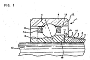
- Fig. 1 is an axial cross-sectional view of a rolling bearing apparatus according to a first embodiment of the present invention.
- Fig. 2 is an axial cross-sectional view of a rolling bearing apparatus according to a second embodiment of the invention.
- Fig. 3 is an axial cross-sectional view of a rolling bearing apparatus according to a third embodiment of the invention.
- Fig. 1 is an axial cross-sectional view of a rolling bearing apparatus according to a first embodiment of the invention.
- the rolling bearing apparatus is mounted in a turbo-molecular pump.
- the rolling bearing apparatus comprises a single row angular contact bearing 1 (which is one example of rolling bearings), and an inner ring contact member 2.
- the angular contact ball bearing 1 is disposed between a rotation shaft 10 of the turbo-molecular pump and a housing (not shown).
- the angular contact ball bearing 1 comprises an inner ring 3, an outer ring 4, balls 5, and a cage 6.
- the inner ring 3 is fitted on an outer peripheral surface of the rotation shaft 10 extending generally in a vertical direction, and is fixed thereto.
- the outer ring 4 is fitted in an inner peripheral surface of the housing to be fixed thereto.
- the outer ring 4 has an outer portion 12 disposed axially outwardly of one axial end surface 11 of the inner ring 3.
- the plurality of balls 5 are held between a raceway groove of the inner ring 3 and a raceway groove of the outer ring 4 by the cage 6, and are arranged at predetermined intervals in a circumferential direction.
- the cage 6 includes a first annular portion 13 disposed at one side thereof in the axial direction, a second annular portion 14 disposed at the other side thereof in the axial direction, and a plurality of pillar portions (not shown) interconnecting the first and second annular portions 13 and 14.
- the first annular portion 13 is disposed axially inwardly of the end surface 11 of the inner ring 3.
- the inner ring contact member 2 is fitted on the outer peripheral surface of the rotation shaft 10 to be fixed thereto.
- the inner ring contact member 2 is disposed at one side of the inner ring 3 in the axial direction, and more specifically at the lower side of the inner ring 3 in the vertical direction.
- the inner ring contact member 2 abuts against the inner ring 3 in the axial direction, and this inner ring contact member 2 has an abutment surface 15 abutting against the end surface 11 of the inner ring 3.
- the inner ring contact member 2 has an outer peripheral surface of a conical or tapering shape.
- the conical outer peripheral surface 16 is smoothly communicated to the abutment surface 15 through a chamfered portion provided near to a radially-outward edge of the abutment surface 15.
- the outer diameter of the conical outer peripheral surface 16 gradually decreases away from the inner ring 3. Namely, a larger-diameter axial end of the conical outer peripheral surface 16 substantially abuts against the end surface 11 of the inner ring 3.
- the conical outer peripheral surface 16 is disposed radially inwardly of a radially-outward edge of the end surface 11 of the inner ring 11.
- a smaller-diameter axial end portion (lower end portion in the vertical direction) of the conical outer peripheral surface 16 is immersed in an oil reservoir (not shown) filled with fluorine-type lubricating oil.
- the lubricating oil in the oil reservoir rises in the vertical direction along the conical outer peripheral surface 16 (as indicated by arrows a ) under the influence of a centrifugal force produced in accordance with the rotation of the conical outer peripheral surface 16, and reaches the end surface 11 of the inner ring 3, and further moves radially outwardly along the end surface 11 of the inner ring 3 as indicated by arrow b .
- the lubricating oil reaching the radially-outward edge of the end surface 11 is sent out radially outwardly from the end surface 11 of the inner ring 3 to the inner peripheral surface of the outer ring 3.
- the larger-diameter end of the conical outer peripheral surface 16 is connected to the one end surface 11 of the inner ring 3 with substantially no clearance formed therebetween, and also the outer ring 4 has the outer portion 12 disposed axially outwardly of the end surface 11 of the inner ring 3.
- this lubricating oil of a minute amount can be fed sequentially along the conical outer peripheral surface 16 and the end surface 11 of the inner ring 3, and can be guided to the inner peripheral surface of the outer ring 4 under the influence of a centrifugal force produced in accordance with the rotation of the conical outer peripheral surface 16 and the inner ring 3. Therefore, even a minute amount of lubricating oil can be smoothly and efficiently supplied to the interior of the angular contact ball bearing 1. Further, the minute lubrication of the angular contact ball bearing 1 can be achieved, and a running torque attributable to a lubricating oil agitation loss can be remarkably reduced.
- the rolling bearing mounted on the rotation shaft 10 is the single row angular contact bearing 1.
- the rolling bearing mounted on the rotation shaft 10 may be a double row angular contact ball bearing or a deep groove ball bearing.
- the rolling bearing mounted on the rotation shaft 10 may be other rolling bearing (such as a tapered roller bearing, a cylindrical roller bearing, etc.) than the ball bearing.
- the inner ring contact member 2 is separate from the rotation shaft 10, and is fitted on the rotation shaft 10 to be fixed thereto.
- the inner ring contact member may be formed by part of a modified rotation shaft. More specifically, the rotation shaft may have a conical outer peripheral surface formed on the outer peripheral surface thereof in adjacent relation to that portion of the outer peripheral surface on which the inner ring is fixedly mounted.
- the shoulder portion of the raceway groove of the inner ring disposed close to the conical outer peripheral surface 16 has a cylindrical outer peripheral surface.
- at least part of the outer peripheral surface of this shoulder portion may be formed into such a shape that its outer diameter is gradually increasing toward the rolling elements.
- Fig. 2 is an axial cross-sectional view of a rolling bearing apparatus according to a second embodiment of the invention.
- the rolling bearing apparatus differs from the rolling bearing apparatus according to the first embodiment in that an inner ring 103 has a shorter axial length and that one axial end surface 111 of the inner ring 103 disposed close to a conical outer peripheral surface 116 is disposed so as to overlap with a first annular portion 13 of a cage 6 (which is close to the conical outer peripheral surface 116) in a radial direction.
- those constituent portions identical to those of the rolling bearing apparatus according to the first embodiment will be designated by identical reference numerals, respectively, and description thereof will be omitted. Also, with respect to the rolling bearing apparatus according to the second embodiment, description of the same operational effects and modified examples as those of the rolling bearing apparatus according to the first embodiment will be omitted, and only those constructions, operational effects and modified examples different from those of the rolling bearing apparatus according to the first embodiment will be described.
- the axial length of the inner ring 103 of an angular contact ball bearing 101 is reduced, and the axial end surface 111 of the inner ring 103 disposed close to the conical outer peripheral surface 116 is disposed so as to overlap with the first annular portion 13 of the cage 6 in the radial direction, as described above.
- the first annular portion 13 of the cage 6 is disposed closer to the conical outer peripheral surface 116 than balls 5 are.
- the first annular portion 13 forms a conical surface-side portion of the cage 6.
- An inner ring contact member 102 is disposed at a lower side of the inner ring 103 in a vertical direction.
- the inner ring contact member 102 abuts against the inner ring 103 in the axial direction, and has an abutment surface 115 abutting against the end surface 111 of the inner ring 103.
- the inner ring contact member 102 is made longer than the inner ring contact member 2 by an amount corresponding to the difference in axial length between the inner ring 2 and the inner ring 102.
- the inner ring contact member according to the first embodiment is used as the inner ring contact member according to the second embodiment, the axial length of the rolling bearing can be reduced, and therefore the rolling bearing apparatus can be formed into a compact design.
- the first annular portion 13 of the cage 6 is disposed so as to overlap with the end surface 111 of the inner ring 103 in the radial direction, and therefore lubricating oil, sent out radially outwardly from the inner ring 103 under the influence of a centrifugal force produced in accordance with the rotation of the inner ring 103 and the inner ring contact member 102, reaches an inner peripheral surface of the first annular portion 13 of the cage 6.
- the cage 6 has such a structure that the two annular portions 13 and 14 are interconnected by a plurality of pillar portions.
- the cage may be a crown type cage having an annular portion formed only at that side thereof which is disposed close to the conical outer peripheral surface.
- Fig. 3 is an axial cross-sectional view of a rolling bearing apparatus according to a third embodiment of the invention.
- the rolling bearing apparatus according to the third embodiment differs from the rolling bearing apparatus according to the second embodiment in that an inner peripheral surface 230 of a first annular portion 213 (which is a conical surface-side portion) of a cage 206 is gradually increasing in diameter in an axial direction toward balls 5.
- those constituent portions identical to those of the rolling bearing apparatus according to the second embodiment will be designated by identical reference numerals, respectively, and description thereof will be omitted. Also, with respect to the rolling bearing apparatus according to the third embodiment, description of the same operational effects and modified examples as those of the rolling bearing apparatuses according to the first and second embodiments will be omitted, and only those constructions, operational effects and modified examples different from those of the rolling bearing apparatuses according to the first and second embodiments will be described.
- the inner peripheral surface 230 of the first annular portion 213 (which is the conical surface-side portion) of the cage 206 is gradually increasing in diameter in the axially-inward direction (toward balls 5). More specifically, the inner peripheral surface 230 in its axial cross-section has a shape of part of a parabola such that the diameter of the inner peripheral surface 230 is gradually increasing in the axially-inward direction.
- the inner peripheral surface 230 of the first annular portion 213 of the cage 206 is gradually increasing in diameter in the axial direction toward the balls 5, and therefore lubricating oil reaching the inner peripheral surface 230 of the first annular portion 213 of the cage 206 can be smoothly guided toward the balls 5. Therefore, insufficient lubrication of ball guide surfaces of the cage 206 can be prevented, and also the amount of the lubricating oil reaching the balls 5 and raceway grooves of inner and outer rings 103 and 4 (which are disposed adjacent to the first annular portion 213 of the cage 206 in the axial direction) can be more increased. Therefore, the amount of the lubricating oil to be supplied to the rolling bearing apparatus can be more decreased, and therefore the running torque can be more reduced.
- the inner peripheral surface 230 of the first annular portion 213 (which forms the conical surface-side portion) of the cage has the parabolic-shape in its axial cross-section.
- the inner peripheral surface of the first annular portion (which forms the conical surface-side portion) of the cage may have any other suitable shape in so far as it has such a shape that its diameter is gradually increasing in the axially-inward direction.
- the inner peripheral surface of the first annular portion may has a conical shape such that its inner diameter is gradually increasing in the axially-inward direction.
Landscapes
- Engineering & Computer Science (AREA)
- General Engineering & Computer Science (AREA)
- Mechanical Engineering (AREA)
- Rolling Contact Bearings (AREA)
Claims (6)
- Wälzlagervorrichtung, umfassend:- einen drehbaren Innenring (3; 103);- einen feststehenden Außenring (4);- Wälzelemente (5), die zwischen Laufringnuten des Innenrings (3; 103) und des Außenrings (4) angeordnet sind; und- ein Innenring-Kontaktelement (2; 102) mit einer Mittelachse, die im Wesentlichen mit einer Mittelachse des Innenrings (3; 103) übereinstimmt, wobei das Innenring-Kontaktelement (2; 102) eine Anlagefläche (15; 115) umfasst, die gegen eine axiale Endoberfläche (11; 111) des Innenrings (3; 103) anliegt,- wobei das Innenring-Kontaktelement (2; 102) eine konische Außenumfangsfläche (16; 116) aufweist, die mit der Anlagefläche (15; 115) in Verbindung steht und deren Außendurchmesser vom Innenring (3; 103) weg allmählich abnimmt, und- wobei der Außenring (4) einen Außenbereich umfasst, der axial auswärts der Endoberfläche (11; 111) des Innenrings (3; 103) angeordnet ist,- dadurch gekennzeichnet, dass die konische Außenumfangsfläche (16; 116) radial einwärts einer radial nach außen gerichteten Kante der Endoberfläche (11; 111) des Innenrings (3; 103) angeordnet ist,- wobei die axiale Richtung des Innenrings (3; 103) entlang der vertikalen Richtung angeordnet ist,- wobei die Wälzlagervorrichtung so angeordnet ist, dass das Innenring-Kontaktelement (2; 102) an einer vertikal abgesenkten Seite in Bezug auf den Innenring (3; 103) liegt, und- wobei die axiale Endoberfläche (11; 111), gegen die die Anlagefläche (15; 115) anliegt, radial auswärts der gegenüberliegenden axialen Endoberfläche des Innenrings (3; 103) vorsteht.
- Wälzlagervorrichtung nach Anspruch 1, wobei die konische Außenumfangsfläche (16; 116) über einen abgeschrägten Bereich mit der Anlagefläche (15; 115) in Verbindung steht.
- Wälzlagervorrichtung nach Anspruch 1, ferner umfassend ein ringförmiges Gehäuse (6; 206), das zwischen dem Innenring (3; 103) und dem Außenring (4) angeordnet ist und jeweils Aussparungen zum Aufnehmen der Wälzelemente (5) umfasst,- wobei das Gehäuse (6; 106) einen konischen oberflächenseitigen Bereich (13; 213) umfasst, der in der axialen Richtung näher an der konischen Außenumfangsfläche (16; 116) als die Wälzelemente (5) angeordnet ist; und- wobei der konische oberflächenseitige Bereich (13; 213) so angeordnet ist, dass er mit der Endoberfläche (11; 111) des Innenrings (3; 103) in der radialen Richtung überlappt.
- Wälzlagervorrichtung nach Anspruch 3, wobei eine Innenumfangsfläche (230) des konischen oberflächenseitigen Bereichs (213) des Gehäuses in Richtung zu den Wälzelementen (5) in der axialen Richtung im Durchmesser allmählich zunimmt.
- Wälzlagervorrichtung nach einem der Ansprüche 1 bis 4, wobei ein Schmieröl ein Schmieröl vom Fluortyp ist.
- Turbomolekularpumpe, umfassend:- eine Drehwelle (10);- ein Gehäuse; und- die Wälzlagervorrichtung nach einem der Ansprüche 1 bis 5, wobei der Innenring (3; 103) und das Innenring-Kontaktelement (2; 102) auf einer Außenumfangsfläche der Drehwelle (10) eingepasst sind und der Außenring (4) in eine Innenumfangsfläche des Gehäuses eingepasst ist.
Applications Claiming Priority (1)
| Application Number | Priority Date | Filing Date | Title |
|---|---|---|---|
| JP2006259114A JP4605130B2 (ja) | 2006-09-25 | 2006-09-25 | 転がり軸受装置 |
Publications (3)
| Publication Number | Publication Date |
|---|---|
| EP1903230A1 EP1903230A1 (de) | 2008-03-26 |
| EP1903230B1 EP1903230B1 (de) | 2009-11-25 |
| EP1903230B2 true EP1903230B2 (de) | 2013-02-27 |
Family
ID=38895975
Family Applications (1)
| Application Number | Title | Priority Date | Filing Date |
|---|---|---|---|
| EP07018746A Expired - Fee Related EP1903230B2 (de) | 2006-09-25 | 2007-09-24 | Wälzlagervorrichtung |
Country Status (4)
| Country | Link |
|---|---|
| US (1) | US8529134B2 (de) |
| EP (1) | EP1903230B2 (de) |
| JP (1) | JP4605130B2 (de) |
| DE (1) | DE602007003416D1 (de) |
Families Citing this family (4)
| Publication number | Priority date | Publication date | Assignee | Title |
|---|---|---|---|---|
| CN104033498A (zh) * | 2013-03-06 | 2014-09-10 | Skf公司 | 滚动轴承 |
| DE102013207494A1 (de) * | 2013-04-25 | 2014-10-30 | Schaeffler Technologies Gmbh & Co. Kg | Wälzlagerkäfig für ein Radiallager |
| US9958005B2 (en) * | 2015-10-13 | 2018-05-01 | Shimadzu Corporation | Oil-lubricated bearing device and vacuum pump |
| GB2562493B (en) * | 2017-05-16 | 2020-12-30 | Edwards Ltd | Pump bearing lubrication |
Citations (5)
| Publication number | Priority date | Publication date | Assignee | Title |
|---|---|---|---|---|
| US264043A (en) † | 1882-09-05 | Joshua p | ||
| US4502274A (en) † | 1982-03-26 | 1985-03-05 | S.N.E.C.M.A. | Lubricating and cooling system for intershaft bearing of turbojet |
| US5183342A (en) † | 1991-12-16 | 1993-02-02 | General Electric Company | Lubricated bearing assembly |
| DE69101765T2 (de) † | 1990-10-01 | 1994-08-25 | Dow Corning | Schmierfettzusammensetzungen die ein Vinylidenfluoridhexafluoroisobutencopolymer als Verdickungsmittel verwenden. |
| JPH09236096A (ja) † | 1996-02-29 | 1997-09-09 | Nippon Seiko Kk | 磁気浮上式ターボ分子ポンプのロータ軸支持構造 |
Family Cites Families (25)
| Publication number | Priority date | Publication date | Assignee | Title |
|---|---|---|---|---|
| US1180338A (en) * | 1915-03-16 | 1916-04-25 | Franz Symanzik | Spinning-spindle. |
| US2762664A (en) * | 1955-01-21 | 1956-09-11 | Bendix Aviat Corp | Bearing lubrication system |
| US2838348A (en) * | 1956-04-17 | 1958-06-10 | Gen Electric | High speed anti-friction bearings |
| GB962204A (en) * | 1963-01-31 | 1964-07-01 | Rolls Royce | Bearing assembly |
| US3619017A (en) * | 1970-04-09 | 1971-11-09 | North American Rockwell | Low-stress ball bearings |
| DE2854298C3 (de) * | 1978-12-15 | 1981-06-04 | Anschuetz & Co Gmbh, 2300 Kiel | Schmierstoffkreislauf für das Lager einer umlaufenden Welle |
| US4342489A (en) * | 1980-10-07 | 1982-08-03 | Teledyne Industries, Inc. | Bearing lubricating injector |
| US4541738A (en) * | 1983-08-11 | 1985-09-17 | The Timken Company | Refrigerant cooled tapered roller bearing assembly |
| US4932500A (en) * | 1989-08-21 | 1990-06-12 | Honeywell Inc. | Lubrication insertion system |
| JP2584936Y2 (ja) * | 1992-08-19 | 1998-11-11 | 日本精工株式会社 | ターボチャージャー用玉軸受 |
| JPH10299689A (ja) | 1997-04-21 | 1998-11-10 | Daikin Ind Ltd | 排気ポンプ |
| JP2001099161A (ja) * | 1999-09-29 | 2001-04-10 | Nsk Ltd | 軸 受 |
| JP2001165177A (ja) * | 1999-12-08 | 2001-06-19 | Nippon Skf Kk | 軸受潤滑装置 |
| JP2001208085A (ja) * | 2000-01-26 | 2001-08-03 | Nsk Ltd | 転がり軸受装置用潤滑装置 |
| DE10103023B4 (de) * | 2000-01-26 | 2005-10-20 | Nsk Ltd | Schmierungssystem für ein Wälzlager |
| JP4396037B2 (ja) | 2000-04-20 | 2010-01-13 | 日本精工株式会社 | 転がり軸受用潤滑装置 |
| JP2002061592A (ja) * | 2000-08-21 | 2002-02-28 | Osaka Vacuum Ltd | 分子ポンプの油循環ポンプ装置 |
| JP4131312B2 (ja) * | 2000-10-27 | 2008-08-13 | 日本精工株式会社 | 軸受装置 |
| DE10115295A1 (de) | 2001-03-28 | 2002-10-02 | Maier & Soehne Unitas | Festoniermaschine |
| US20030069144A1 (en) * | 2001-05-11 | 2003-04-10 | Nsk Ltd. | Rolling bearing |
| US20040175065A1 (en) * | 2003-03-07 | 2004-09-09 | Minebea Co., Ltd. | Ball bearing assembly utilizing a labyrinth seal |
| JP3849672B2 (ja) * | 2003-06-05 | 2006-11-22 | 日産自動車株式会社 | 複軸多層モータの軸受潤滑構造 |
| JP4471150B2 (ja) * | 2003-11-05 | 2010-06-02 | Ntn株式会社 | 車輪用軸受装置およびその製造方法 |
| WO2006041040A1 (ja) * | 2004-10-08 | 2006-04-20 | Ntn Corporation | 転がり軸受 |
| JP2006125485A (ja) * | 2004-10-28 | 2006-05-18 | Ntn Corp | 転がり軸受の潤滑装置 |
-
2006
- 2006-09-25 JP JP2006259114A patent/JP4605130B2/ja not_active Expired - Fee Related
-
2007
- 2007-09-24 EP EP07018746A patent/EP1903230B2/de not_active Expired - Fee Related
- 2007-09-24 US US11/902,639 patent/US8529134B2/en active Active
- 2007-09-24 DE DE602007003416T patent/DE602007003416D1/de active Active
Patent Citations (5)
| Publication number | Priority date | Publication date | Assignee | Title |
|---|---|---|---|---|
| US264043A (en) † | 1882-09-05 | Joshua p | ||
| US4502274A (en) † | 1982-03-26 | 1985-03-05 | S.N.E.C.M.A. | Lubricating and cooling system for intershaft bearing of turbojet |
| DE69101765T2 (de) † | 1990-10-01 | 1994-08-25 | Dow Corning | Schmierfettzusammensetzungen die ein Vinylidenfluoridhexafluoroisobutencopolymer als Verdickungsmittel verwenden. |
| US5183342A (en) † | 1991-12-16 | 1993-02-02 | General Electric Company | Lubricated bearing assembly |
| JPH09236096A (ja) † | 1996-02-29 | 1997-09-09 | Nippon Seiko Kk | 磁気浮上式ターボ分子ポンプのロータ軸支持構造 |
Non-Patent Citations (1)
| Title |
|---|
| "Konstruktionszeichnung des SKF-Wälzlagers "Explorer"", SKF HAUPTKATALOG, 1 January 2005 (2005-01-01), pages 452 - 453 † |
Also Published As
| Publication number | Publication date |
|---|---|
| JP4605130B2 (ja) | 2011-01-05 |
| EP1903230A1 (de) | 2008-03-26 |
| US8529134B2 (en) | 2013-09-10 |
| US20080075400A1 (en) | 2008-03-27 |
| DE602007003416D1 (de) | 2010-01-07 |
| EP1903230B1 (de) | 2009-11-25 |
| JP2008075857A (ja) | 2008-04-03 |
Similar Documents
| Publication | Publication Date | Title |
|---|---|---|
| EP2562437B1 (de) | Verfahren zum schmieren eines schrägkugellagers und kugellagerkäfig | |
| JP5129762B2 (ja) | アンギュラ玉軸受 | |
| EP2386772B1 (de) | Wälzlager mit interner Schmierung | |
| CN109563879B (zh) | 滚珠轴承、主轴装置以及机床 | |
| EP1947356A2 (de) | Käfig für ein Wälzlager und Wälzlager damit | |
| EP1903230B2 (de) | Wälzlagervorrichtung | |
| WO2018034245A1 (ja) | 軸受装置、及び工作機械用主軸装置 | |
| KR20190026820A (ko) | 볼 베어링, 및 공작 기계용 주축 장치 | |
| JP2006071016A (ja) | 玉軸受用保持器 | |
| CN201106625Y (zh) | 一种高速铝箔轧机用止推轴承 | |
| WO2018034246A1 (ja) | 玉軸受、及び工作機械用主軸装置 | |
| US10197094B2 (en) | Double-row spherical roller bearing | |
| JP4126529B2 (ja) | 円すいころ軸受 | |
| JP4322641B2 (ja) | 円筒ころ軸受 | |
| EP2017487A2 (de) | Kegelrollenlager mit am Käfig angeordneten Schmiernuten | |
| KR102647697B1 (ko) | 텐덤 볼 베어링 | |
| JP4341743B2 (ja) | ころ軸受 | |
| JPH0138329Y2 (de) | ||
| CN109563877B (zh) | 滚珠轴承和机床用主轴装置 | |
| US10167897B2 (en) | Tapered roller bearing | |
| JP4322650B2 (ja) | 円筒ころ軸受 | |
| CN217130090U (zh) | 滚动轴承 | |
| JP2012071398A (ja) | スピンドル装置 | |
| EP3492760B1 (de) | Kugellager | |
| US9732793B2 (en) | Bearing and bearing arrangement |
Legal Events
| Date | Code | Title | Description |
|---|---|---|---|
| PUAI | Public reference made under article 153(3) epc to a published international application that has entered the european phase |
Free format text: ORIGINAL CODE: 0009012 |
|
| AK | Designated contracting states |
Kind code of ref document: A1 Designated state(s): AT BE BG CH CY CZ DE DK EE ES FI FR GB GR HU IE IS IT LI LT LU LV MC MT NL PL PT RO SE SI SK TR |
|
| AX | Request for extension of the european patent |
Extension state: AL BA HR MK YU |
|
| 17P | Request for examination filed |
Effective date: 20080925 |
|
| 17Q | First examination report despatched |
Effective date: 20081028 |
|
| AKX | Designation fees paid |
Designated state(s): DE FR |
|
| GRAP | Despatch of communication of intention to grant a patent |
Free format text: ORIGINAL CODE: EPIDOSNIGR1 |
|
| GRAS | Grant fee paid |
Free format text: ORIGINAL CODE: EPIDOSNIGR3 |
|
| GRAA | (expected) grant |
Free format text: ORIGINAL CODE: 0009210 |
|
| AK | Designated contracting states |
Kind code of ref document: B1 Designated state(s): DE FR |
|
| REF | Corresponds to: |
Ref document number: 602007003416 Country of ref document: DE Date of ref document: 20100107 Kind code of ref document: P |
|
| PLBI | Opposition filed |
Free format text: ORIGINAL CODE: 0009260 |
|
| 26 | Opposition filed |
Opponent name: SKF GMBH Effective date: 20100824 |
|
| PLAX | Notice of opposition and request to file observation + time limit sent |
Free format text: ORIGINAL CODE: EPIDOSNOBS2 |
|
| PLAN | Information deleted related to communication of a notice of opposition and request to file observations + time limit |
Free format text: ORIGINAL CODE: EPIDOSDOBS2 |
|
| PLAX | Notice of opposition and request to file observation + time limit sent |
Free format text: ORIGINAL CODE: EPIDOSNOBS2 |
|
| PLBB | Reply of patent proprietor to notice(s) of opposition received |
Free format text: ORIGINAL CODE: EPIDOSNOBS3 |
|
| PUAH | Patent maintained in amended form |
Free format text: ORIGINAL CODE: 0009272 |
|
| STAA | Information on the status of an ep patent application or granted ep patent |
Free format text: STATUS: PATENT MAINTAINED AS AMENDED |
|
| 27A | Patent maintained in amended form |
Effective date: 20130227 |
|
| AK | Designated contracting states |
Kind code of ref document: B2 Designated state(s): DE FR |
|
| REG | Reference to a national code |
Ref country code: DE Ref legal event code: R102 Ref document number: 602007003416 Country of ref document: DE Effective date: 20130227 |
|
| REG | Reference to a national code |
Ref country code: FR Ref legal event code: PLFP Year of fee payment: 10 |
|
| PGFP | Annual fee paid to national office [announced via postgrant information from national office to epo] |
Ref country code: FR Payment date: 20160816 Year of fee payment: 10 |
|
| REG | Reference to a national code |
Ref country code: FR Ref legal event code: ST Effective date: 20180531 |
|
| PG25 | Lapsed in a contracting state [announced via postgrant information from national office to epo] |
Ref country code: FR Free format text: LAPSE BECAUSE OF NON-PAYMENT OF DUE FEES Effective date: 20171002 |
|
| PGFP | Annual fee paid to national office [announced via postgrant information from national office to epo] |
Ref country code: DE Payment date: 20200909 Year of fee payment: 14 |
|
| REG | Reference to a national code |
Ref country code: DE Ref legal event code: R119 Ref document number: 602007003416 Country of ref document: DE |
|
| PG25 | Lapsed in a contracting state [announced via postgrant information from national office to epo] |
Ref country code: DE Free format text: LAPSE BECAUSE OF NON-PAYMENT OF DUE FEES Effective date: 20220401 |