EP1901939B1 - Siege de vehicule, notamment de vehicule a moteur - Google Patents
Siege de vehicule, notamment de vehicule a moteur Download PDFInfo
- Publication number
- EP1901939B1 EP1901939B1 EP06754650A EP06754650A EP1901939B1 EP 1901939 B1 EP1901939 B1 EP 1901939B1 EP 06754650 A EP06754650 A EP 06754650A EP 06754650 A EP06754650 A EP 06754650A EP 1901939 B1 EP1901939 B1 EP 1901939B1
- Authority
- EP
- European Patent Office
- Prior art keywords
- backrest
- vehicle seat
- use position
- backrest support
- fitting
- Prior art date
- Legal status (The legal status is an assumption and is not a legal conclusion. Google has not performed a legal analysis and makes no representation as to the accuracy of the status listed.)
- Active
Links
- 230000007704 transition Effects 0.000 claims abstract description 10
- 230000033001 locomotion Effects 0.000 claims description 16
- 230000008878 coupling Effects 0.000 claims description 11
- 238000010168 coupling process Methods 0.000 claims description 11
- 238000005859 coupling reaction Methods 0.000 claims description 11
- 230000000903 blocking effect Effects 0.000 abstract 1
- 230000005540 biological transmission Effects 0.000 description 2
- 230000003993 interaction Effects 0.000 description 2
- 230000003111 delayed effect Effects 0.000 description 1
- 230000001419 dependent effect Effects 0.000 description 1
- 230000001360 synchronised effect Effects 0.000 description 1
- 230000002123 temporal effect Effects 0.000 description 1
Images


Classifications
-
- B—PERFORMING OPERATIONS; TRANSPORTING
- B60—VEHICLES IN GENERAL
- B60N—SEATS SPECIALLY ADAPTED FOR VEHICLES; VEHICLE PASSENGER ACCOMMODATION NOT OTHERWISE PROVIDED FOR
- B60N2/00—Seats specially adapted for vehicles; Arrangement or mounting of seats in vehicles
- B60N2/24—Seats specially adapted for vehicles; Arrangement or mounting of seats in vehicles for particular purposes or particular vehicles
- B60N2/32—Seats specially adapted for vehicles; Arrangement or mounting of seats in vehicles for particular purposes or particular vehicles convertible for other use
- B60N2/36—Seats specially adapted for vehicles; Arrangement or mounting of seats in vehicles for particular purposes or particular vehicles convertible for other use into a loading platform
-
- B—PERFORMING OPERATIONS; TRANSPORTING
- B60—VEHICLES IN GENERAL
- B60N—SEATS SPECIALLY ADAPTED FOR VEHICLES; VEHICLE PASSENGER ACCOMMODATION NOT OTHERWISE PROVIDED FOR
- B60N2/00—Seats specially adapted for vehicles; Arrangement or mounting of seats in vehicles
- B60N2/24—Seats specially adapted for vehicles; Arrangement or mounting of seats in vehicles for particular purposes or particular vehicles
- B60N2/30—Non-dismountable or dismountable seats storable in a non-use position, e.g. foldable spare seats
- B60N2/3002—Non-dismountable or dismountable seats storable in a non-use position, e.g. foldable spare seats back-rest movements
- B60N2/3029—Non-dismountable or dismountable seats storable in a non-use position, e.g. foldable spare seats back-rest movements by composed movement
- B60N2/3031—Non-dismountable or dismountable seats storable in a non-use position, e.g. foldable spare seats back-rest movements by composed movement in a longitudinal-vertical plane
-
- B—PERFORMING OPERATIONS; TRANSPORTING
- B60—VEHICLES IN GENERAL
- B60N—SEATS SPECIALLY ADAPTED FOR VEHICLES; VEHICLE PASSENGER ACCOMMODATION NOT OTHERWISE PROVIDED FOR
- B60N2/00—Seats specially adapted for vehicles; Arrangement or mounting of seats in vehicles
- B60N2/24—Seats specially adapted for vehicles; Arrangement or mounting of seats in vehicles for particular purposes or particular vehicles
- B60N2/30—Non-dismountable or dismountable seats storable in a non-use position, e.g. foldable spare seats
- B60N2/3088—Non-dismountable or dismountable seats storable in a non-use position, e.g. foldable spare seats characterised by the mechanical link
- B60N2/309—Non-dismountable or dismountable seats storable in a non-use position, e.g. foldable spare seats characterised by the mechanical link rods
-
- B—PERFORMING OPERATIONS; TRANSPORTING
- B60—VEHICLES IN GENERAL
- B60N—SEATS SPECIALLY ADAPTED FOR VEHICLES; VEHICLE PASSENGER ACCOMMODATION NOT OTHERWISE PROVIDED FOR
- B60N2/00—Seats specially adapted for vehicles; Arrangement or mounting of seats in vehicles
- B60N2/24—Seats specially adapted for vehicles; Arrangement or mounting of seats in vehicles for particular purposes or particular vehicles
- B60N2/32—Seats specially adapted for vehicles; Arrangement or mounting of seats in vehicles for particular purposes or particular vehicles convertible for other use
- B60N2/36—Seats specially adapted for vehicles; Arrangement or mounting of seats in vehicles for particular purposes or particular vehicles convertible for other use into a loading platform
- B60N2002/363—Seats specially adapted for vehicles; Arrangement or mounting of seats in vehicles for particular purposes or particular vehicles convertible for other use into a loading platform characterised by provisions for enhancing the cargo floor surface, e.g. elements closing gaps or enlarging the back-rest surface
Definitions
- the invention relates to a vehicle seat, in particular a motor vehicle seat, with the features of the preamble of claim 1.
- the backrest structure either by unlocking their locking device forward in a table position or by unlocking the fitting together with backrest carrier to the rear in a reclining position pivotally. To load the vehicle would be desirable in some cases a deeper non-use position.
- a vehicle seat in which the backrest structure is articulated by means of hinged backrest support to a base and releasably locked at its lower end to the base.
- a tilt adjustment with multiple positions of use is not provided.
- a seat cushion structure is hinged by hinged wings also on the base and releasably locked at its rear end to the base. In the transition from the use position to the non-use position pivots the unlocked backrest structure forward and the backrest support to the rear, while independently the seat cushion structure is pivoted by slightly more than 180 ° to the front.
- a rail is provided on each vehicle seat side, in which run rollers, which are provided on the one hand at the front end of the seat cushion structure and on the other hand at the lower end of the backrest structure.
- run rollers which are provided on the one hand at the front end of the seat cushion structure and on the other hand at the lower end of the backrest structure.
- the original underside of the seat cushion structure includes more or less flush and just to the original back of the underlying backrest structure.
- the WO 03/026919 A1 proposes a generic vehicle seat of the type mentioned above.
- the locking device of the backrest structure is first released, so that the backrest structure pivots relative to the backrest support forward in the horizontal to a stop.
- a locking device of the backrest support is to be solved, so that the user can swing the backrest support to the rear until the backrest structure rests against the vehicle floor.
- the US 3 202 453 A discloses a vehicle seat, the transition from a einitzbaren use position in a flat non-use position by means of a slotted guide for the seat cushion structure and the backrest fixedly mounted thereon, wherein the backrest structure pivots relative to the backrest support to the front.
- the backrest structure unfolds a loading floor at its upper end.
- the invention is based on the object to improve a vehicle seat of the type mentioned. This object is achieved by a vehicle seat with the features of claim 1.
- Advantageous embodiments are the subject of the dependent claims.
- unlocked backrest structure By the unlocked backrest structure to the front and the restrained by the backrest structure unlocked backrest carrier pivots backwards when compared to a table position deeper non-use position (bottom position) can be achieved, which is suitable in contrast to a reclining position for loading at the transition from the use position to the non-use position. Improvements can be achieved by certain end positions of the joint and / or a hollow in the vehicle structure.
- the two latches i. the fitting and the locking device, allow a simpler design of the backrest support (for example, as a simple rocker) and more extensive areas of movement, while for example a four-bar linkage as a backrest only needs a lock, but more articulated parts and has a limited mobility.
- the backrest defined Due to the serial locking of the backrest structure with the backrest support and the backrest support with the seat part structure, the backrest defined thereby forms a kinematic unit.
- This kinematic unit is adjustable in a preferred embodiment by means of the fitting as a whole in its inclination. For an increase in seating comfort for the occupant, it is sufficient if only the backrest structure is tilt adjustable.
- the positively controlled unlocking of the fitting simplifies the operation to be carried out by the user, for example because he only has to unlock the locking device of the backrest structure, while the backrest structure unlocks the backrest support, ie acts on the fitting.
- the backrest structure unlocks the fitting by means of a coupling, which is preferably rigid.
- the coupling can provide a free path, such as a slot-pin guide, by means of which the positively controlled unlocking can be delayed and set to a specific pivoting angle range of the backrest structure.
- the movements of the unlocked backrest structure and the unlocked backrest support are preferably largely coordinated or coupled, for example, by a system of cooperating springs or a transmission connection.
- a backrest compensation spring can act on the movement of the backrest support relative to the seat part structure, while another spring unit acts on the movement of the backrest structure relative to the backrest support or relative to the seat part structure.
- the spring end which is assigned to the component to be moved engages eccentrically with respect to its pivot axis, for example on an arm which is attached to the said component or non-rotatably connected thereto.
- exactly one backrest support is provided on each vehicle seat side, for example in the form of a rocker, wherein the two backrest supports may be coupled by transverse connections.
- the intended for the transition between position of use and non-use position springs or transmission connections need only be present on a vehicle seat side, preferably on different vehicle seat sides.
- a spring unit which is provided for acting on the movement of the backrest structure, contribute to a tilt adjustment for compensation of the back weight.
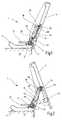
- a vehicle seat 1 is provided for a rear, in particular third, seat row of a motor vehicle, wherein the arrangement of the vehicle seat 1 within the motor vehicle and its usual direction of travel define the directional information used below.
- the vehicle seat 1 has a seat part structure 3 and a backrest structure 4, which are upholstered in a manner known per se.
- the seat part structure 3 may be formed in an articulated manner.
- the seat part structure 3 is presently firmly connected to the vehicle structure S of the motor vehicle, but could also by means of Seat rails relative to the vehicle structure S be adjustable in length.
- a fitting 7 is provided on the seat part structure 3, by means of which each one designed as a rocker backrest support 8 is mounted relative to the seat part structure 3 pivotally and lockable.
- the two backrest support 8 together with the upholstered backrest structure 4 define the backrest of the vehicle seat 1. It is first described a einitzbare use position of the vehicle seat 1.
- the fitting 7 is presently designed as a detent fitting, as he, for example, with respect to the internal configuration in the WO 00/44582 A1 and with respect to its external configuration in the DE 101 05 282 A1 is described, the disclosure of which is expressly incorporated.
- one of the two fittings is firmly connected to the seat part structure 3 at the rear end and the other fitting firmly connected to the backrest support 8 at its lower end.
- fitting 7 a geared fitting with pivoting function, as he, for example, in the DE 100 48 127 A1 is described, whose disclosure content is also expressly included.
- the normally locked fitting 7 can be unlocked by means of a first actuating element 11 in that the first actuating element 11 designed as an angle lever rotates a shaft 13. It can be provided for each fitting 7 each have a shaft 13 or a common shaft 13 for both fittings 7, which couples the two fittings 7 and allows a synchronous release by means of a single first actuating elements 11.
- the shaft 13 is aligned with the axis of rotation of the fittings 7, so the pivot axis of the backrest support 8, relative to the seat part structure 3.
- a second actuating element 15 which in the present case designed as a lever handle is unlockable.
- the second actuating element 15 is rotatably connected to the first actuating element 11 or acts directly on the shaft 13, wherein entrainment or decoupling may be provided.
- a Lehnenkompensationsfeder 17 which is presently designed as a spiral spring, acts between the seat part structure 3 and the backrest support 8 and the fitting parts attached thereto. Compensated for unlocked fittings 7 the backrest compensation spring 17 at least a part of the weight of the entire backrest.
- the backrest structure 4 is articulated on both sides of the vehicle by means of a hinge 18 designed as a hinge on the backrest support 8.
- the hinge 18 is provided between the upper end of the backrest support 8 and a forwardly projecting arm 20 of the backrest structure 4 in the lower half thereof.
- the axes of rotation defined by the joints 18 are aligned with each other and define the pivot axis of the backrest structure 4 relative to the backrest support 8.
- the back of the backrest structure 4 in the position of use substantially to the rear, slightly oblique to the horizontal.
- a locking device 22 is provided on at least one vehicle seat side, in the present case on both.
- the locking device 22 is presently designed as a lock, such as in the DE 203 02 007 U1 whose disclosure content is explicitly included.
- the backrest structure 4 is releasably locked to the associated backrest support 8, more precisely with a counter element 23 on the associated backrest support 8, in this case a striker of the backrest support 8.
- Locking device 22 and counter element 23 can be reversed in their positions.
- Defined by the backrest structure 4 and the backrest support 8 back thereby forms in the use position a kinematic unit.
- the fittings 7 more use positions of this unit are adjustable, ie the back, so in particular the backrest structure 4, is adjustable in inclination.
- a fitting in the manner of the fitting 7 may be provided.
- a lean-structure-fixed control pin 24 projects laterally from the arm 20 or is otherwise attached to the backrest structure 4.
- a coupling 26 is articulated at one end to the first actuating element 11 and at the other end to the control pin 24 rotatably and limited slidably coupled, by enclosing it with a slot 28.
- a spring unit 30, in the present case a gas spring used as a tension spring, is attached on the one hand to the seat part structure 3 and on the other hand to the arm 20. The latter components may be provided on a vehicle seat side or on both vehicle seat sides.
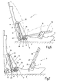
- the vehicle seat 1 can be transferred from the use position to a flat ground or non-use position. For this purpose - if necessary after lowering or folding the seat cushion - the locking device 22 is unlocked and the backrest structure 4 pivoted relative to the backrest support 8 about the joint 18 to the front.
- the spring unit 30 initially counteracts this movement.
- the control pin 24 moves in the slot 28 upwards, so passes through a free path.
- a particular intermediate position i. at a certain pivoting angle or at least in a specific pivoting angle range of the backrest structure 4, for example, when the spring unit 30 exceeds a dead center, the control pin 24 reaches the end of the slot 28 and takes the coupling 26 with which the fitting 7 forcibly controlled by the first actuating element 11 unlocked.
- the backrest support 8 When both fittings 7 are unlocked, the backrest support 8 can be pivoted to the rear in the horizontal. At the same time, the backrest structure 4 continues its pivoting movement in the direction of the horizontal. In this case, the control pin 24 moves back in the slot 28.
- the torque built up by the Lehnenkompensationsfeder 17 forward or upward can be compensated for at least approximately by the built-up of the spring unit 30 torque down at a suitable vote.
- the interaction of the Lehnenkompensationsfeder 17 and the spring unit 30 defines a high degree of motion or forced guidance of backrest structure 4 and backrest support 8.
- the motion adjustment can also be achieved by a gear connection of the fitting 7 and the joint 18, for example by means of gears and timing belt.
- the non-use position is reached when both the backrest support 8 and the backrest structure 4 have at least approximately reached the horizontal.
- the latter components of the back together with upholstery can be partially absorbed by a trough of the vehicle structure S.
- the formerly upper part of the backrest is arranged above the seat part structure 3, while the former lower part projects into the recess.
- the peculiarity that the backrest structure 4 rests with its formerly lower and now the rear end on the vehicle structure S more precisely, when reaching the non-use position in a suitable recording of the vehicle structure S sets.
- the now upwardly facing, original back of the backrest structure 4 then flush and just with the underlying, fixed part of the loading floor and from itself forms part of the now continuous loading floor. Securing the non-use position is possible by re-locking the fittings 7 and / or the locking devices 22 to correspondingly positioned counter elements.
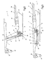
- the first actuating element 11 is arranged at that end of the shaft 13 which is arranged on the vehicle seat side closer to the vehicle center, referred to briefly as the inside of the vehicle seat 1.
- the second actuator 15 is disposed at that end of the shaft 13 which is on the vehicle seat side is arranged closer to the vehicle exterior, referred to briefly as the outside of the vehicle seat 1.
- the arm 20 On the inside of the vehicle seat 1, the arm 20 is arranged in the region of the associated joint 18, which arm is connected in a rotationally fixed manner to the backrest structure 4.
- the upper end of the backrest compensation spring 17 In alignment with the pivot axis of the backrest structure 4 defined by the joints 18, for example on a bearing pin of the joint 18, the upper end of the backrest compensation spring 17 is articulated.
- the backrest compensation spring 17 is presently designed as a gas spring.
- the lower end of the backrest compensation spring 17 is hinged to the seat part structure.
- the upper end of the coupling 26 On the arm 20, that is eccentric to the joint 18, the upper end of the coupling 26 is articulated.
- the coupling 26 is arranged so that the slot 28 is located at the lower end. By means of the slot 28, the coupling 26 surrounds the control pin 24.
- the control pin 24 is arranged on the first actuating element 11, and eccentric to the pivot axis of the fittings 7, with which the shaft 13 is aligned.
- a further arm 20 is arranged in the region of the associated joint 18, which arm is likewise connected in a rotationally fixed manner to the backrest structure 4.
- the upper end of the spring unit 30 is articulated.
- the spring unit 30 is presently designed as a gas spring.
- the lower end of the spring unit 30 is hinged to the seat part structure 3.
- the seat part structure 3 introduced so far only as an assembly in both exemplary embodiments comprises a base 31, two rockers 33 and a seat cushion structure 35.
- the base 31 is the previously described part of the seat part structure 3 which is directly or indirectly connected to the vehicle structure S and on which the fittings 7 and the two springs 17 and 30 are attached directly or indirectly with one end.
- On each side of the vehicle is one of the two Swinging 33 hinged with one end.
- the other end of each rocker 33 is hinged to the seat cushion structure 35.
- the mutually corresponding joints on the two sides of the vehicle are aligned with each other.
- the seat cushion structure 35 may be hinged in a modified version directly to the base 31, ie by means of a single pivot axis which is defined by two mutually aligned joints.
- the seat cushion structure 35 together with its padding defines the seat cushion of the vehicle seat 1.
- springs can be effective and build up a bias.
- the underside of the seat cushion structure 35 points in the position of use substantially downwards, slightly oblique to the vertical.
- the seat cushion structure 35 by means of at least one second locking device 37, for example a lock on both sides of the backrest structure 4 (or the backrest support 8 or the base 31), and a cooperating second counter-element 39, for example on both sides Bolt on the seat cushion structure 35, locked.
- Second locking device 37 and second counter element 39 may be reversed in their positions.
- the backrest structure 4 for example, by means of a stop or a receptacle, hold the seat cushion structure 35 in the position of use in a modified embodiment.
- backrest structure 4 In the transition from the use position to the non-use position is not only the above-described relative movement of backrest structure 4, backrest support 8 and seat part structure 3 (more precisely, the base 31), but it is also the second locking device 37 unlocked.
- the backrest structure 4 When the backrest structure 4 has reached approximately a vertical intermediate position, it releases the pivoting range of the seat cushion structure 35. Thereafter, the seat cushion structure 35 is pre-pivoted, in this case by a little more than 180 °, so that the original underside of the seat cushion structure 35 is horizontally oriented and facing upward. This movement is supported in the present case by the said, built by the springs on the rocker 33 bias, so it is automatic.
- the original underside of the seat cushion structure 35 includes more or less flush and just to the original back of the underlying backrest structure 4 and thus forms another part of the now continuous loading floor.
- the vehicle seat 1 is used in the third row of seats, preferably a non-use position of the vehicle seats of the second row of seats is provided, according to which the original back of the associated back of the second row of seats is more or less flush and level with the original underside of the seat cushion structure 35 of the third row of seats connects.
- the loading floor is thereby increased even more.
Landscapes
- Engineering & Computer Science (AREA)
- Aviation & Aerospace Engineering (AREA)
- Transportation (AREA)
- Mechanical Engineering (AREA)
- Seats For Vehicles (AREA)
- Chairs For Special Purposes, Such As Reclining Chairs (AREA)
Abstract
Claims (11)
- Siège de véhicule, en particulier siège de véhicule automobile, avec une structure de partie d'assise (3), avec au moins un support de dossier (8) qui est articulé de manière verrouillable sur la structure de partie d'assise (3) et avec une structure de dossier (4) qui est articulée sur le support de dossier (8) à l'aide d'une articulation (18) et qui peut être verrouillée avec le support de dossier (8) à l'aide d'un dispositif de verrouillage (22), le siège de véhicule (1) étant apte à être déplacé entre une position d'usage permettant de s'asseoir et une position de non-usage à plat par un déverrouillage et un pivotement du support de dossier (8) et/ou de la structure de dossier (4), où, dans la transition entre la position d'usage et la position de non-usage, seul le dispositif de verrouillage (22) est d'abord déverrouillé et la structure de dossier (4) déverrouillée est pivotée vers l'avant, après quoi le support de dossier (8) déverrouillé est pivoté vers l'arrière, caractérisé par le fait que, dans la transition entre la position d'usage et la position de non-usage, dans une position intermédiaire sur une plage déterminée d'angle de pivotement, la structure de dossier (4) déverrouille par actionnement forcé, du fait de son pivotement, au moins une ferrure (7) grâce à laquelle le support de dossier (8) est articulé de manière verrouillable sur la structure de partie d'assise (3).
- Siège de véhicule selon la revendication 1, caractérisé par le fait qu'il est prévu, entre la structure de dossier (4) et un premier élément d'actionnement (11) de la ferrure (7), une bielle (26) de déverrouillage par actionnement forcé.
- Siège de véhicule selon la revendication 2, caractérisé par le fait que la bielle (26) prévoit une course à vide, la course à vide étant parcourue sur une plage déterminée d'angle de pivotement de la structure de dossier (4), après quoi la bielle (26) entre en action.
- Siège de véhicule selon la revendication 3, caractérisé par le fait que, pour réaliser la course à vide, la structure de dossier (4) ou le premier élément d'actionnement (11) possède un tourillon (24) et la bielle (26) porte à son extrémité correspondante une fente (28) avec laquelle elle coopère.
- Siège de véhicule selon l'une des revendications précédentes, caractérisé par le fait que des ressorts (17, 30) et/ou une liaison par transmission font se correspondre les mouvements de la structure de dossier (4) déverrouillée et du support de dossier (8) déverrouillé.
- Siège de véhicule selon la revendication 5, caractérisé par le fait qu'un des ressorts (17, 30) dépasse une position de point mort sur la plage déterminée d'angle de pivotement de la structure de dossier (4).
- Siège de véhicule selon l'une des revendications précédentes, caractérisé par le fait que, dans la position de non-usage, l'articulation (18) est située plus bas que la ferrure (7).
- Siège de véhicule selon l'une des revendications précédentes, caractérisé par le fait qu'une cuvette de la structure du véhicule (S), dans la position de non-usage, reçoit au moins partiellement le dossier formé par le support de dossier (8), la structure de dossier (4) et leur rembourrage.
- Siège de véhicule selon l'une des revendications précédentes, caractérisé par le fait que, dans la position d'usage, la structure de dossier (4) peut être réglée en inclinaison à l'aide de la ferrure (7).
- Siège de véhicule selon l'une des revendications précédentes, caractérisé par le fait que la structure de partie d'assise (3) comprend une structure de coussin d'assise (35) qui est apte à pivoter, en particulier automatiquement, entre la position d'usage et la position de non-usage, de préférence d'environ plus de 180 ° par rapport à une base (31), à l'aide d'au moins une coulisse (33) ou directement autour d'un axe de pivotement.
- Siège de véhicule selon la revendication 10, caractérisé par le fait que le pivotement entre la position d'usage et la position de non-usage s'effectue à l'aide d'une précontrainte qui est appliquée en particulier par des ressorts entre la base (31), éventuellement les coulisses (33), et la structure de coussin d'assise (35) dès que la structure de dossier (4) a atteint une certaine position intermédiaire.
Priority Applications (1)
| Application Number | Priority Date | Filing Date | Title |
|---|---|---|---|
| PL06754650T PL1901939T3 (pl) | 2005-07-08 | 2006-07-01 | Siedzenie pojazdu, w szczególności siedzenie pojazdu mechanicznego |
Applications Claiming Priority (2)
| Application Number | Priority Date | Filing Date | Title |
|---|---|---|---|
| DE102005032382A DE102005032382B4 (de) | 2005-07-08 | 2005-07-08 | Fahrzeugsitz, insbesondere Kraftfahrzeugsitz |
| PCT/EP2006/006422 WO2007006440A2 (fr) | 2005-07-08 | 2006-07-01 | Siege de vehicule, notamment de vehicule a moteur |
Publications (2)
| Publication Number | Publication Date |
|---|---|
| EP1901939A2 EP1901939A2 (fr) | 2008-03-26 |
| EP1901939B1 true EP1901939B1 (fr) | 2011-12-21 |
Family
ID=37307056
Family Applications (1)
| Application Number | Title | Priority Date | Filing Date |
|---|---|---|---|
| EP06754650A Active EP1901939B1 (fr) | 2005-07-08 | 2006-07-01 | Siege de vehicule, notamment de vehicule a moteur |
Country Status (8)
| Country | Link |
|---|---|
| US (1) | US7628449B2 (fr) |
| EP (1) | EP1901939B1 (fr) |
| JP (1) | JP4990893B2 (fr) |
| KR (1) | KR101277143B1 (fr) |
| CN (1) | CN101213109B (fr) |
| DE (1) | DE102005032382B4 (fr) |
| PL (1) | PL1901939T3 (fr) |
| WO (1) | WO2007006440A2 (fr) |
Families Citing this family (11)
| Publication number | Priority date | Publication date | Assignee | Title |
|---|---|---|---|---|
| DE102007019711B4 (de) | 2007-04-26 | 2009-11-19 | Keiper Gmbh & Co. Kg | Fahrzeugsitz, insbesondere Kraftfahrzeugsitz |
| DE102008012714B3 (de) * | 2008-03-03 | 2009-10-15 | Keiper Gmbh & Co. Kg | Fahrzeugsitz, insbesondere Kraftfahrzeugsitz |
| DE202009000783U1 (de) * | 2009-01-20 | 2010-06-17 | Twb-Presswerk Gmbh & Co. Kg | Fahrzeugsitz |
| US8505999B2 (en) * | 2009-06-29 | 2013-08-13 | Honda Motor Company, Ltd. | Vehicular seat assembly and vehicles including same |
| US8196990B2 (en) | 2010-04-07 | 2012-06-12 | Honda Motor Company, Ltd. | Vehicular seat assembly and vehicles including same |
| WO2012006941A1 (fr) * | 2010-07-12 | 2012-01-19 | Zhang Xingliang | Siège passager et unité d'assise à double usage fauteuil-lit assemblée, unité d'assise à usages multiples |
| DE102010050074A1 (de) * | 2010-10-29 | 2012-05-03 | Bayerische Motoren Werke Aktiengesellschaft | Kraftfahrzeug |
| CN103153697B (zh) * | 2010-11-19 | 2016-06-22 | 张兴亮 | 乘客座椅和组合坐卧两用座椅单元、多用座椅单元 |
| DE102010052273A1 (de) | 2010-11-23 | 2012-05-24 | Keiper Gmbh & Co. Kg | Entriegelungseinheit für einen Fahrzeugsitz |
| DE102011101879B4 (de) * | 2011-05-12 | 2013-12-24 | Keiper Gmbh & Co. Kg | Fahrzeugsitz, insbesondere Kraftfahrzeugsitz |
| DE102011113789B4 (de) * | 2011-08-29 | 2014-04-24 | Keiper Gmbh & Co. Kg | Fahrzeugsitz, insbesondere Kraftfahrzeugsitz |
Family Cites Families (26)
| Publication number | Priority date | Publication date | Assignee | Title |
|---|---|---|---|---|
| US3202453A (en) * | 1963-07-09 | 1965-08-24 | Ford Motor Co | Retractable seat |
| DE3828659A1 (de) * | 1987-09-11 | 1989-03-23 | Volkswagen Ag | Gelenkbeschlag fuer einen fahrzeugsitz mit verstellbarer rueckenlehne |
| DE19811190C2 (de) * | 1998-03-14 | 1999-12-16 | Daimler Chrysler Ag | Sitzanordnung für Fahrzeuge |
| JPH11348625A (ja) * | 1998-06-09 | 1999-12-21 | Ikeda Bussan Co Ltd | 自動車のフラット化シート構造 |
| JPH11348624A (ja) * | 1998-06-09 | 1999-12-21 | Ikeda Bussan Co Ltd | 自動車のフラット化シート構造 |
| JPH11348634A (ja) * | 1998-06-12 | 1999-12-21 | Nissan Motor Co Ltd | 車両用アームレスト |
| JP3926485B2 (ja) * | 1998-07-27 | 2007-06-06 | ジョンソン コントロールズ オートモーティブ システムズ株式会社 | 自動車のフラット化シート構造 |
| DE19904300C1 (de) * | 1999-01-28 | 2000-08-03 | Keiper Gmbh & Co | Rastbeschlag für einen Fahrzeugsitz |
| DE19943891C1 (de) * | 1999-09-14 | 2000-11-16 | Faure Bertrand Sitztech Gmbh | Sitz oder Sitzbank für den Kofferraum- bzw. Laderaumbereich eines Kraftfahrzeuges |
| US6540295B1 (en) * | 2000-01-13 | 2003-04-01 | Lear Corporation | Vehicle seat |
| DE10048127B4 (de) * | 2000-09-28 | 2008-05-29 | Keiper Gmbh & Co.Kg | Beschlag für einen Fahrzeugsitz |
| US6464297B2 (en) * | 2000-12-01 | 2002-10-15 | Dura Global Technologies | Load floor seat assembly |
| CA2431167A1 (fr) * | 2000-12-11 | 2002-06-20 | Intier Automotive Inc. | Ensemble siege escamotable avec coussin de siege en porte-a-faux |
| JP4580563B2 (ja) * | 2001-01-29 | 2010-11-17 | ジョンソン コントロールズ オートモーティブ システムズ株式会社 | 車両のフラット化シート構造 |
| DE10105282B4 (de) * | 2001-02-06 | 2005-03-24 | Keiper Gmbh & Co. Kg | Beschlag für einen Fahrzeugsitz |
| JP2002240607A (ja) * | 2001-02-20 | 2002-08-28 | Takashimaya Nippatsu Kogyo Co Ltd | 格納式シート |
| FR2829441B1 (fr) * | 2001-09-13 | 2004-01-02 | Renault | Siege pour vehicule automobile |
| DE10146711A1 (de) * | 2001-09-21 | 2003-04-24 | Intier Automotive Seating Germ | Kraftfahrzeugrücksitz |
| DE10156644C2 (de) * | 2001-11-17 | 2003-10-23 | Keiper Gmbh & Co Kg | Fahrzeugsitz mit Bodenstellung |
| JP4000556B2 (ja) * | 2002-01-29 | 2007-10-31 | トヨタ紡織株式会社 | 車両用シート |
| US6598926B1 (en) * | 2002-10-09 | 2003-07-29 | General Motors Corporation | Transformable rear seat for a vehicle |
| DE10260277A1 (de) * | 2002-12-20 | 2004-07-01 | Bayerische Motoren Werke Ag | Fahrzeugsitz mit einem Sitzteil und einer Rückenlehne |
| DE20302007U1 (de) * | 2003-02-08 | 2003-04-24 | Keiper Gmbh & Co Kg | Verriegelungsvorrichtung für einen Fahrzeugsitz |
| DE20304713U1 (de) * | 2003-03-17 | 2004-07-29 | Brose Fahrzeugteile Gmbh & Co. Kg, Coburg | Kraftfahrzeugsitz, insbesondere Rücksitz für ein Kraftfahrzeug |
| DE102004024225B3 (de) * | 2004-05-15 | 2005-05-25 | Faurecia Autositze Gmbh & Co. Kg | Fahrzeugsitz |
| FR2877283B1 (fr) * | 2004-10-29 | 2007-01-26 | Faurecia Sieges Automobile | Siege escamotable dans le plancher |
-
2005
- 2005-07-08 DE DE102005032382A patent/DE102005032382B4/de not_active Expired - Fee Related
-
2006
- 2006-07-01 EP EP06754650A patent/EP1901939B1/fr active Active
- 2006-07-01 PL PL06754650T patent/PL1901939T3/pl unknown
- 2006-07-01 WO PCT/EP2006/006422 patent/WO2007006440A2/fr not_active Application Discontinuation
- 2006-07-01 JP JP2008519843A patent/JP4990893B2/ja active Active
- 2006-07-01 US US11/816,579 patent/US7628449B2/en active Active
- 2006-07-01 KR KR1020077019633A patent/KR101277143B1/ko active IP Right Grant
- 2006-07-01 CN CN2006800244071A patent/CN101213109B/zh active Active
Also Published As
| Publication number | Publication date |
|---|---|
| CN101213109A (zh) | 2008-07-02 |
| DE102005032382A1 (de) | 2007-01-11 |
| JP2009500224A (ja) | 2009-01-08 |
| EP1901939A2 (fr) | 2008-03-26 |
| US20080143163A1 (en) | 2008-06-19 |
| WO2007006440A3 (fr) | 2007-05-24 |
| CN101213109B (zh) | 2010-09-08 |
| WO2007006440A2 (fr) | 2007-01-18 |
| US7628449B2 (en) | 2009-12-08 |
| KR20080020981A (ko) | 2008-03-06 |
| JP4990893B2 (ja) | 2012-08-01 |
| KR101277143B1 (ko) | 2013-06-20 |
| DE102005032382B4 (de) | 2010-09-16 |
| PL1901939T3 (pl) | 2012-05-31 |
Similar Documents
| Publication | Publication Date | Title |
|---|---|---|
| EP1901939B1 (fr) | Siege de vehicule, notamment de vehicule a moteur | |
| EP1488950B1 (fr) | Siège de véhicule, en particulier siège d'automobile | |
| EP1545928B1 (fr) | Ensemble siege pour un vehicule a moteur | |
| DE102006007139B4 (de) | Fahrzeugsitz, insbesondere Kraftfahrzeugsitz | |
| EP2707250B1 (fr) | Siège de véhicule, en particulier siège de véhicule automobile | |
| WO2015173108A1 (fr) | Siège de véhicule, en particulier siège de véhicule automobile | |
| EP2750927B1 (fr) | Siège de véhicule, notamment siège de véhicule à moteur | |
| WO2018046433A1 (fr) | Siège de véhicule | |
| EP1625966A2 (fr) | Siège véhicule avec position abaissée au niveau du plancher | |
| WO2017012990A1 (fr) | Siège de véhicule, en particulier siège de véhicule à moteur | |
| WO2019048399A1 (fr) | Siège pivotant de véhicule | |
| EP0943482A2 (fr) | Agencement d'au moins deux sièges adjacents, en particulier une rangée de sièges d'un véhicule automobile | |
| DE102008019527B4 (de) | Fahrzeugsitz, insbesondere Kraftfahrzeugsitz | |
| DE202006005525U1 (de) | Sitzschienenpaar für einen Fahrzeugsitz | |
| EP0943483A2 (fr) | Agencement d'au moins deux sièges adjacents | |
| EP2723609B1 (fr) | Siège de véhicule, en particulier siège de véhicule à moteur | |
| DE102005022985B3 (de) | Fahrzeugsitz, insbesondere Kraftfahrzeugsitz | |
| DE102008012714B3 (de) | Fahrzeugsitz, insbesondere Kraftfahrzeugsitz | |
| DE202006004491U1 (de) | Fahrzeugsitz, insbesondere Kraftfahrzeugsitz | |
| DE102005022984B4 (de) | Fahrzeugsitz, insbesondere Kraftfahrzeugsitz | |
| DE202005020672U1 (de) | Fahrzeugsitz, insbesondere Kraftfahrzeugsitz | |
| DE102014214563B4 (de) | Fahrzeugsitz, insbesondere Kraftfahrzeugsitz | |
| DE102006015922B4 (de) | Sitzschienenpaar für einen Fahrzeugsitz | |
| DE102009060130B4 (de) | Fahrzeugsitz, insbesondere Kraftfahrzeugsitz | |
| DE202006004326U1 (de) | Fahrzeugsitz, insbesondere Kraftfahrzeugsitz |
Legal Events
| Date | Code | Title | Description |
|---|---|---|---|
| PUAI | Public reference made under article 153(3) epc to a published international application that has entered the european phase |
Free format text: ORIGINAL CODE: 0009012 |
|
| 17P | Request for examination filed |
Effective date: 20070713 |
|
| AK | Designated contracting states |
Kind code of ref document: A2 Designated state(s): DE FR GB IT PL |
|
| DAX | Request for extension of the european patent (deleted) | ||
| RBV | Designated contracting states (corrected) |
Designated state(s): DE FR GB IT PL |
|
| 17Q | First examination report despatched |
Effective date: 20110627 |
|
| GRAP | Despatch of communication of intention to grant a patent |
Free format text: ORIGINAL CODE: EPIDOSNIGR1 |
|
| DAX | Request for extension of the european patent (deleted) | ||
| GRAS | Grant fee paid |
Free format text: ORIGINAL CODE: EPIDOSNIGR3 |
|
| GRAA | (expected) grant |
Free format text: ORIGINAL CODE: 0009210 |
|
| AK | Designated contracting states |
Kind code of ref document: B1 Designated state(s): DE FR GB IT PL |
|
| REG | Reference to a national code |
Ref country code: GB Ref legal event code: FG4D Free format text: NOT ENGLISH |
|
| REG | Reference to a national code |
Ref country code: DE Ref legal event code: R096 Ref document number: 502006010740 Country of ref document: DE Effective date: 20120216 |
|
| REG | Reference to a national code |
Ref country code: PL Ref legal event code: T3 |
|
| PLBE | No opposition filed within time limit |
Free format text: ORIGINAL CODE: 0009261 |
|
| STAA | Information on the status of an ep patent application or granted ep patent |
Free format text: STATUS: NO OPPOSITION FILED WITHIN TIME LIMIT |
|
| 26N | No opposition filed |
Effective date: 20120924 |
|
| PG25 | Lapsed in a contracting state [announced via postgrant information from national office to epo] |
Ref country code: IT Free format text: LAPSE BECAUSE OF FAILURE TO SUBMIT A TRANSLATION OF THE DESCRIPTION OR TO PAY THE FEE WITHIN THE PRESCRIBED TIME-LIMIT Effective date: 20111221 |
|
| REG | Reference to a national code |
Ref country code: DE Ref legal event code: R097 Ref document number: 502006010740 Country of ref document: DE Effective date: 20120924 |
|
| GBPC | Gb: european patent ceased through non-payment of renewal fee |
Effective date: 20120701 |
|
| PG25 | Lapsed in a contracting state [announced via postgrant information from national office to epo] |
Ref country code: GB Free format text: LAPSE BECAUSE OF NON-PAYMENT OF DUE FEES Effective date: 20120701 |
|
| REG | Reference to a national code |
Ref country code: DE Ref legal event code: R081 Ref document number: 502006010740 Country of ref document: DE Owner name: JOHNSON CONTROLS COMPONENTS GMBH & CO. KG, DE Free format text: FORMER OWNER: KEIPER GMBH & CO. KG, 67657 KAISERSLAUTERN, DE Effective date: 20140710 Ref country code: DE Ref legal event code: R081 Ref document number: 502006010740 Country of ref document: DE Owner name: ADIENT LUXEMBOURG HOLDING S.A.R.L., LU Free format text: FORMER OWNER: KEIPER GMBH & CO. KG, 67657 KAISERSLAUTERN, DE Effective date: 20140710 Ref country code: DE Ref legal event code: R081 Ref document number: 502006010740 Country of ref document: DE Owner name: ADIENT LUXEMBOURG HOLDING S.A R.L., LU Free format text: FORMER OWNER: KEIPER GMBH & CO. KG, 67657 KAISERSLAUTERN, DE Effective date: 20140710 |
|
| REG | Reference to a national code |
Ref country code: FR Ref legal event code: PLFP Year of fee payment: 10 |
|
| REG | Reference to a national code |
Ref country code: FR Ref legal event code: PLFP Year of fee payment: 11 |
|
| REG | Reference to a national code |
Ref country code: DE Ref legal event code: R081 Ref document number: 502006010740 Country of ref document: DE Owner name: ADIENT US LLC, PLYMOUTH, US Free format text: FORMER OWNER: JOHNSON CONTROLS COMPONENTS GMBH & CO. KG, 67657 KAISERSLAUTERN, DE Ref country code: DE Ref legal event code: R081 Ref document number: 502006010740 Country of ref document: DE Owner name: ADIENT LUXEMBOURG HOLDING S.A.R.L., LU Free format text: FORMER OWNER: JOHNSON CONTROLS COMPONENTS GMBH & CO. KG, 67657 KAISERSLAUTERN, DE Ref country code: DE Ref legal event code: R081 Ref document number: 502006010740 Country of ref document: DE Owner name: ADIENT LUXEMBOURG HOLDING S.A R.L., LU Free format text: FORMER OWNER: JOHNSON CONTROLS COMPONENTS GMBH & CO. KG, 67657 KAISERSLAUTERN, DE |
|
| REG | Reference to a national code |
Ref country code: FR Ref legal event code: PLFP Year of fee payment: 12 |
|
| REG | Reference to a national code |
Ref country code: DE Ref legal event code: R081 Ref document number: 502006010740 Country of ref document: DE Owner name: ADIENT US LLC, PLYMOUTH, US Free format text: FORMER OWNER: ADIENT LUXEMBOURG HOLDING S.A.R.L., LUXEMBOURG, LU Ref country code: DE Ref legal event code: R081 Ref document number: 502006010740 Country of ref document: DE Owner name: ADIENT LUXEMBOURG HOLDING S.A R.L., LU Free format text: FORMER OWNER: ADIENT LUXEMBOURG HOLDING S.A.R.L., LUXEMBOURG, LU |
|
| REG | Reference to a national code |
Ref country code: DE Ref legal event code: R084 Ref document number: 502006010740 Country of ref document: DE |
|
| REG | Reference to a national code |
Ref country code: FR Ref legal event code: PLFP Year of fee payment: 13 |
|
| REG | Reference to a national code |
Ref country code: DE Ref legal event code: R081 Ref document number: 502006010740 Country of ref document: DE Owner name: ADIENT US LLC, PLYMOUTH, US Free format text: FORMER OWNER: ADIENT LUXEMBOURG HOLDING S.A R.L., LUXEMBOURG, LU |
|
| PGFP | Annual fee paid to national office [announced via postgrant information from national office to epo] |
Ref country code: PL Payment date: 20230621 Year of fee payment: 18 |
|
| PGFP | Annual fee paid to national office [announced via postgrant information from national office to epo] |
Ref country code: FR Payment date: 20230725 Year of fee payment: 18 Ref country code: DE Payment date: 20230727 Year of fee payment: 18 |