EP0943483A2 - Agencement d'au moins deux sièges adjacents - Google Patents
Agencement d'au moins deux sièges adjacents Download PDFInfo
- Publication number
- EP0943483A2 EP0943483A2 EP99104729A EP99104729A EP0943483A2 EP 0943483 A2 EP0943483 A2 EP 0943483A2 EP 99104729 A EP99104729 A EP 99104729A EP 99104729 A EP99104729 A EP 99104729A EP 0943483 A2 EP0943483 A2 EP 0943483A2
- Authority
- EP
- European Patent Office
- Prior art keywords
- seat
- backrest
- armrest
- arrangement according
- seat arrangement
- Prior art date
- Legal status (The legal status is an assumption and is not a legal conclusion. Google has not performed a legal analysis and makes no representation as to the accuracy of the status listed.)
- Granted
Links
Images


Classifications
-
- B—PERFORMING OPERATIONS; TRANSPORTING
- B60—VEHICLES IN GENERAL
- B60N—SEATS SPECIALLY ADAPTED FOR VEHICLES; VEHICLE PASSENGER ACCOMMODATION NOT OTHERWISE PROVIDED FOR
- B60N2/00—Seats specially adapted for vehicles; Arrangement or mounting of seats in vehicles
- B60N2/02—Seats specially adapted for vehicles; Arrangement or mounting of seats in vehicles the seat or part thereof being movable, e.g. adjustable
- B60N2/20—Seats specially adapted for vehicles; Arrangement or mounting of seats in vehicles the seat or part thereof being movable, e.g. adjustable the back-rest being tiltable, e.g. to permit easy access
-
- B—PERFORMING OPERATIONS; TRANSPORTING
- B60—VEHICLES IN GENERAL
- B60N—SEATS SPECIALLY ADAPTED FOR VEHICLES; VEHICLE PASSENGER ACCOMMODATION NOT OTHERWISE PROVIDED FOR
- B60N2/00—Seats specially adapted for vehicles; Arrangement or mounting of seats in vehicles
- B60N2/02—Seats specially adapted for vehicles; Arrangement or mounting of seats in vehicles the seat or part thereof being movable, e.g. adjustable
- B60N2/0292—Multiple configuration seats, e.g. for spacious vehicles or mini-buses
-
- B—PERFORMING OPERATIONS; TRANSPORTING
- B60—VEHICLES IN GENERAL
- B60N—SEATS SPECIALLY ADAPTED FOR VEHICLES; VEHICLE PASSENGER ACCOMMODATION NOT OTHERWISE PROVIDED FOR
- B60N2/00—Seats specially adapted for vehicles; Arrangement or mounting of seats in vehicles
- B60N2/75—Arm-rests
- B60N2/753—Arm-rests movable to an inoperative position
-
- B—PERFORMING OPERATIONS; TRANSPORTING
- B60—VEHICLES IN GENERAL
- B60N—SEATS SPECIALLY ADAPTED FOR VEHICLES; VEHICLE PASSENGER ACCOMMODATION NOT OTHERWISE PROVIDED FOR
- B60N2/00—Seats specially adapted for vehicles; Arrangement or mounting of seats in vehicles
- B60N2/75—Arm-rests
- B60N2/763—Arm-rests adjustable
- B60N2/77—Height adjustment
-
- B—PERFORMING OPERATIONS; TRANSPORTING
- B60—VEHICLES IN GENERAL
- B60N—SEATS SPECIALLY ADAPTED FOR VEHICLES; VEHICLE PASSENGER ACCOMMODATION NOT OTHERWISE PROVIDED FOR
- B60N2/00—Seats specially adapted for vehicles; Arrangement or mounting of seats in vehicles
- B60N2/02—Seats specially adapted for vehicles; Arrangement or mounting of seats in vehicles the seat or part thereof being movable, e.g. adjustable
- B60N2002/0204—Seats specially adapted for vehicles; Arrangement or mounting of seats in vehicles the seat or part thereof being movable, e.g. adjustable characterised by the seat or seat part turning about or moving along a non-standard, particular axis, i.e. an axis different from the axis characterising the conventional movement
- B60N2002/0212—Seats specially adapted for vehicles; Arrangement or mounting of seats in vehicles the seat or part thereof being movable, e.g. adjustable characterised by the seat or seat part turning about or moving along a non-standard, particular axis, i.e. an axis different from the axis characterising the conventional movement the seat or seat part turning about or moving along a longitudinal axis
Definitions
- the invention relates to a seating arrangement according to at least two seats arranged side by side the preamble of claim 1.
- DE 41 26 518 A1 describes a vehicle seat, whose backrest is a protruding one Has extension part.
- This extension part can from the roughly vertical normal position to a roughly horizontal, position away from the backrest be transferred in which it will serve as an armrest can.
- Such an armrest can only from one in a rearward position Person can be used as an armrest.
- the invention is based, for a seat arrangement of the type mentioned an armrest to create that easily from the backrest a seat for at least one on an adjacent one Seated person is formed without additional parts are required for this.
- this object is achieved by that the one in the approximately horizontal position Backrest to form an armrest for the neighboring one Seat at least one adjustable in height and / or has pivotable cushion part.
- Beneficial Further developments of the invention are in the subclaims specified.
- the backrest in this way can be a relatively large and comfortable in a few simple steps Armrest are formed. To do this, only the Backrest in a horizontal position and that on the Backrest adjustable upholstered part in one Armrest position are transferred.
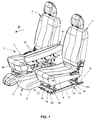
- Fig. 1 shows a row of seats 1 of a not shown Motor vehicle, which three arranged side by side Seats 2, 3, 4, with the middle seat 3 in a located between the two outer seats 2, 4 Is transferred to the non-use position.
- this non-use position is the backrest 5 of the middle Seat 3 in an approximately horizontal position while the hinge-like connected to the backrest 5 Seat part 6 in a lowered position below the Seat parts 7, 8 of the outer seats 2, 4 is located.
- the middle seat 3 in the Non-use position is the seat part 6 in the front and in rear areas via pivot supports 9, 10 (in Fig. 3 shown) connected to the floor 11, the rear Swivel bracket 10 in a manner yet to be explained is so connected to the backrest 5 that when Folding the backrest 5 at the same time the adjustment of the seat part 6 in the position shown in Fig. 1 he follows.
- the two outer seats 2, 4 are connected to the floor 11 both longitudinally and transversely.
- pairs of rails 12, 13 are provided on the respective outer seat 2, 4 in the area of the floor, which are oriented in the seat direction F and each have a lower rail 14, 15 connected to the floor 11 and an upper rail 16 which is displaceably guided on the lower rail 14, 15 , 17 have.
- the upper rails 16, 17 can be locked in various positions by means of devices known per se.
- On the upper rails 16, 17 to adjust the seat 2, 4 transversely to the seat direction F further pairs of rails 18, 19 are arranged, which are oriented transversely to the seat direction F and the respective upper rails 16, 17 of the pairs of rails 12, 13 oriented in the seat direction F at the front and connect with each other at the rear end.
- the pairs of rails 18, 19 oriented transversely to the seat direction F each consist of a guide rail 20, 21 connected to the upper rails 16, 17 and a seat rail 22, 23 slidably mounted thereon and connected to the seat part 2, 4, which, analogously to the upper rail 16, 17 is lockable in different positions.
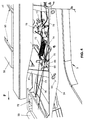
- the details of the middle seat 3 can be seen in particular from FIG. 2, in which the shell of this seat 3 is shown in a position in which a supporting structure 24 of the backrest 5 is in an approximately horizontal position and a supporting seat pan 25 of the seat part 6 are in a lowered position.
- an upwardly extending box-shaped holder 26 is provided on the rear region of the seat shell 25, on which the support structure 24 is articulated about a pivot axis 27 oriented transversely to the seat direction F.
- the support structure 24 is designed as a profiled sheet metal part with local stiffeners and receptacles 28 for a height-adjustable headrest 29.
- a slide 30 is provided for unlocking the backrest 5 in the respective position.
- This slide 30 is connected by cables 31, 32 in a force-transmitting manner to two - as shown in FIG. 3 - spaced-apart and resiliently mounted locking pins 33, 34 in the lower region of the support structure 24.
- the spring-loaded locking pins 33, 34 automatically engage in recesses 35, 36, which are each arranged in a circular segment part 37, 38 of the box-shaped holder 26. In this way, the backrest 5 and thus the entire seat 3 can be unlocked or locked securely and comfortably in the respective position.
- the seat 3 is adjustably connected to the floor 11 in the seat direction F.
- This adjustment is analogous to the adjustment of the outer seats 2, 4, the spaced-apart pairs of rails 39, 40 being connected to the seat pan 25 via the front pivot support 9 and the rear pivot support 10.
- the front pivot support 9 consists of two parallel pivot levers 41, 42, which are connected to each other in the transverse direction by a connecting strut 43. These pivot levers 41, 42 are articulated on the seat shell 25 at the lower end with the upper rails 44, 45 about an axis 46 arranged transversely to the seat direction F and at the upper end about an axis 47 running parallel to the axis 46 arranged at the lower end.
- the rear pivot support 10, which is exposed to a higher load than the front pivot support 9, consists essentially of a plate-shaped sheet metal part 48 with sides 49 set at right angles and is at the lower end about an axis 50 oriented transversely to the seat direction F with the top rails 44 , 45 and connected to the seat shell 25 at the upper end about an axis 51 running parallel to the axis 50 arranged at the lower end.
- Such an arrangement of the pivot supports 9, 10 allows the seat pan 25 or the complete seat 3 to be pivoted into a position further forward and below when it is transferred to the non-use position.
- the backrest 5 is to be simplified when it is not in use via a pivotable coupling element 52 connected to the seat part 6 that when pivoting the backrest 5 about its pivot axis 27 a forced adjustment of the seat part 6 in the front and bottom Position is effected.
- This is the coupling element 52 with its upper end parallel and spaced apart arranged to the pivot axis 27 of the backrest 5 Axis of rotation 53 articulated on the lower region of the support structure 24.
- the lower end of the coupling element 52 is one parallel to the axis of rotation 53 arranged at the upper end extending axis of rotation 54 on the rear pivot support 10 articulated near the upper axis 51.
- These axes of rotation 53, 54 are spatial and kinematic with respect to the Pivot axis 27 of the backrest 5, the upper axis 51 and the lower axis 50 of the rear pivot support 10 is selected that when pivoting the backrest 5 to the Swivel axis 27 at the same time - due to the coupling connection (Coupling element 52) - a pivoting of the Swivel support 10 in the same direction around the lower axis 50 takes place.
- the angle of rotation of the backrest 5 between the approximately vertical and the approximately horizontal Position so on the corresponding angle of rotation rear pivot support 10 matched that after the transfer the backrest 5 in the approximately horizontal position the seat part 6 - as shown in Fig. 2 - in the lowered position.
- An armrest 55 can be formed between the two outer seats 2, 4 of the row of seats 1, if required, as shown in FIG. 1, from the backrest 5 of the middle seat 3 which is in the non-use position.
- a support plate 56 is provided on the backrest 5 parallel to itself in a higher, so-called table position, on which two cushion parts 57 designed in mirror image fashion are pivotably articulated.
- FIG. 2 The structure and the connection of such a support plate 56 to the support structure 24 of the backrest 5 is shown in FIG. 2.
- the support plate 56 which has approximately a flat surface 58, is displaced together with the approximately box-shaped support elements 59 of the upholstery parts 57 articulated thereon in the elevated table position, in which the upper sides 60 of the support elements 59 and the support plate 56 form an approximately horizontal, flat storage surface .
- two rockers 61, 62 arranged approximately parallel and at a distance from one another are provided, which are designed as plate-shaped sheet metal stamping parts.
- rockers 61, 62 are at the respective lower end via a horizontally and transversely to the seat direction F axis 63, 64 with the support structure 24 of the backrest 5 and at the respective upper end via an axis parallel to the axis 63, 64 arranged at the lower end 65, 66 articulated to the support plate 56.
- the rockers 61, 62 pivot about the respective lower axes 63, 64 and thus steer the support plate 56 into the rest position provided on the support structure 24 and lying further forward.
- the support plate 56 forms, together with the support elements 59 on the back of the backrest 5, an approximately horizontal, flat surface, the height of which corresponds approximately to the height of the loading space surface 67 located behind the seats 2, 3, 4.
- the support plate 56 is both in the table position and lockable in the rest position.
- the locking in the table position is done - how shown in Fig. 4 - by means of a on the support structure 24 rotatably mounted first pawl 68, which is shown in the Position provided on the front rocker 61 Locking bolt 69 engages.
- the locking bolt 69 is at an approximately right angle spaced from the axis 63 of the front rocker 61. When swiveling the front rocker 61 clockwise the locking bolt thus also moves 69 circular around the axis 63 until it locks itself through the first pawl 68 which is in the circular Path of the locking bolt 69 protrudes and by a leg spring 70 resilient in the locking position is held.
- the locking of the support plate 56 in the rest position is done in a similar way to locking in the table position.
- a second locking bolt arranged on the support plate 56 which is shown in FIG Position of the support plate 56 is not visible.
- To unlock this second locking bolt is the second pawl 75 via a second cable 76 with the Sliding button 72 connected, which thus the support plate 56th both in the table position and in the rest position can unlock.
- the cushion parts 57 must be pivoted into the armrest position shown in FIG. 1 and locked in this position.
- Such a structure of the armrest 55 is shown in FIG. 5 for clarification without the associated upholstery.
- the respective support elements 59 of the armrest 55 are supported by three lever arms 79, which are each pivotably and also axially displaceably mounted in a bearing block 80 arranged on the support plate 56.
- the pivoting of the support elements 59 takes place in each case about an axis 81, 82 arranged on the support plate 56, which is formed by bearing bolts 83 aligned approximately parallel to the seat direction F and firmly connected to the respective bearing block 80.
- the bearing bolts 83 each pass through an elongated hole 84 provided on the lever arms 79, which is aligned in the longitudinal direction of the lever arm 79.
- link guides 85 are also provided, each for a guide pin 86 which is fixedly connected to the respective lever arm 79, in order to achieve an automatic fixation of the support elements 59 in the armrest position.
- transverse slots 90 for each lever arm 79 trained which such a pivoting of the lever arms 79 and thus also the support elements 59 between the Allow table position and armrest position.
- the guide pins slide during this pivoting movement 86 along the circular sections 88 of the link guides 85 that at the same time an axial displacement the lever arms 79 corresponding to the axial extent the elongated holes 84 takes place.
- latch guide pins 86 in each one arranged at the end of the slide guides 85 Locking recess 89 a, the backward displacement of the support elements 59 down and thereby a fixation of the respective Carrying elements 59 allows in the armrest position.
- Support elements 59 are very simple in the table position to convict.
- the support elements 59 only have to are raised slightly so that the guide pins 86 the lever arms 79 out of engagement with the corresponding ones Locking recesses 89 come. After that, the unlocked one Support elements 59 comfortably in the approximately horizontal Table position can be pivoted.
- the seating comfort on the two outer seats 2, 4 can be increased even further in that after the transfer of the cushion parts 57 into the armrest position, the outer seats 2, 4 transversely to the seat direction F can be adjusted inwards into the space that has become free by reducing the width of the backrest 5. This results in more free space, especially in the head area, for those in these seats 2, 4. People.
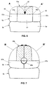
- FIG. 6 An alternative embodiment of a seat 3a one relatively easy to convert into an armrest 55a Backrest 5a is shown in Fig. 6.
- the backrest 5a is folded against the seat part 6a and forms in this position with its flat back surface about an horizontal shelf.
- the backrest 5a consists of a supporting middle section 91, on which two mirror images cushion parts 57a arranged on both sides thereof are pivoted about an axis 81a, 82a. These cushion parts 57a can be pivoted about 180 ° according to the respective arrow A, A 'in the in Fig. 6th Hatched armrest position transferred become.
- the upholstery parts form in this armrest position 57a with their padded upper sides 92 the support surface the armrest 55a.
- the padded sides 92 of the cushion parts 57a both to form the support surface of the armrest 55a as also to form the support surface of the backrest 5a for the person sitting on this seat 3a is used.
- a Seat 3b is its backrest 5b - as in FIG. 7 shown - by two mirror images of each other Upholstery parts 57b formed, which are not closer to one shown way on a segment-shaped Support structure 24b are pivotally mounted. These upholstery parts 57b can be pivoted by approximately 90 ° according to the respective arrow B, B 'in the hatched in Fig. 7 Armrest position are transferred, whereby a comfortable armrest 55b is formed.
- This execution the seat 5b is also easy to use and can - like the previously described version of the seat 3a - instead of that with FIGS. 1 to 5 described design of the seat 3 in the row of seats 1 be used.
Landscapes
- Engineering & Computer Science (AREA)
- Aviation & Aerospace Engineering (AREA)
- Transportation (AREA)
- Mechanical Engineering (AREA)
- Seats For Vehicles (AREA)
- Chairs Characterized By Structure (AREA)
Applications Claiming Priority (2)
| Application Number | Priority Date | Filing Date | Title |
|---|---|---|---|
| DE19812137 | 1998-03-20 | ||
| DE19812137A DE19812137A1 (de) | 1998-03-20 | 1998-03-20 | Sitzanordnung mit zumindest zwei nebeneinander angeordneten Sitzen |
Publications (3)
| Publication Number | Publication Date |
|---|---|
| EP0943483A2 true EP0943483A2 (fr) | 1999-09-22 |
| EP0943483A3 EP0943483A3 (fr) | 2001-08-16 |
| EP0943483B1 EP0943483B1 (fr) | 2004-12-08 |
Family
ID=7861584
Family Applications (1)
| Application Number | Title | Priority Date | Filing Date |
|---|---|---|---|
| EP99104729A Expired - Lifetime EP0943483B1 (fr) | 1998-03-20 | 1999-03-10 | Agencement d'au moins deux sièges adjacents d'une rangée de sièges d'un véhicule automobile |
Country Status (4)
| Country | Link |
|---|---|
| EP (1) | EP0943483B1 (fr) |
| BR (1) | BR9903042A (fr) |
| DE (2) | DE19812137A1 (fr) |
| ES (1) | ES2234178T3 (fr) |
Cited By (13)
| Publication number | Priority date | Publication date | Assignee | Title |
|---|---|---|---|---|
| WO2001003968A1 (fr) * | 1999-07-09 | 2001-01-18 | Lear Corporation | Siege de vehicule |
| EP0943485A3 (fr) * | 1998-03-20 | 2002-04-17 | Bertrand Faure Sitztechnik GmbH & Co. KG | Siège de véhicule à dossier rabattable |
| FR2819762A1 (fr) * | 2001-01-25 | 2002-07-26 | Faurecia Ind | Ensemble d'appui pour un occupant d'un vehicule automobile et vehicule automobile correspondant |
| FR2828147A1 (fr) * | 2001-08-06 | 2003-02-07 | Renault | Banquette a assise modulable, pour vehicule |
| EP1728677A1 (fr) * | 2005-05-30 | 2006-12-06 | C.R.F. Società Consortile per Azioni | Ensemble de siège avec un dossier rabattable pour un véhicule automobile |
| DE102008004232B3 (de) * | 2008-01-14 | 2009-04-02 | GM Global Technology Operations, Inc., Detroit | Sitzanordnung mit zwei Fahrzeugsitzen in einer Sitzreihe |
| GB2459028A (en) * | 2008-04-08 | 2009-10-14 | Gm Global Tech Operations Inc | Motor vehicle seat having a wing rest having a cover plate. |
| GB2459029A (en) * | 2008-04-08 | 2009-10-14 | Gm Global Tech Operations Inc | Vehicle seat with pivotable and height adjustable wing rests |
| US8496290B2 (en) | 2008-04-08 | 2013-07-30 | GM Global Technology Operations LLC | Motor vehicle seat with preloaded wing-rest and seat arrangement with such a motor vehicle seat |
| CN101554844B (zh) * | 2008-04-08 | 2013-08-21 | Gm全球科技运作股份有限公司 | 带有可纵向移动的中间座椅的汽车座椅装置 |
| CN101554850B (zh) * | 2008-04-08 | 2013-08-21 | Gm全球科技运作股份有限公司 | 有靠背的汽车座椅和有这种汽车座椅的座席装置 |
| EP3181394A1 (fr) * | 2015-12-18 | 2017-06-21 | Renault S.A.S. | Banquette de vehicule modulable apte a liberer un passage axial |
| RU2712499C1 (ru) * | 2019-01-28 | 2020-01-29 | Виктор Владимирович Малышев | Разделитель зоны размещения локтей соседних пассажиров на общем подлокотнике между креслами транспортного средства |
Families Citing this family (1)
| Publication number | Priority date | Publication date | Assignee | Title |
|---|---|---|---|---|
| DE102004018161B3 (de) * | 2004-04-14 | 2005-08-11 | Faurecia Autositze Gmbh & Co. Kg | Rückenlehne mit Ausstellplatte |
Citations (1)
| Publication number | Priority date | Publication date | Assignee | Title |
|---|---|---|---|---|
| DE4126518A1 (de) | 1991-08-10 | 1993-02-11 | Grammer Ag | Fahrzeugsitz |
Family Cites Families (9)
| Publication number | Priority date | Publication date | Assignee | Title |
|---|---|---|---|---|
| US3893729A (en) * | 1974-11-18 | 1975-07-08 | Mc Donnell Douglas Corp | Convertible passenger seat |
| DE3937678A1 (de) * | 1988-11-25 | 1990-05-31 | Volkswagen Ag | Schwenkbare armlehne |
| US4944552A (en) * | 1989-03-17 | 1990-07-31 | Weber Aircraft, Inc. | Stowable table system |
| DE4213218A1 (de) * | 1992-04-22 | 1993-10-28 | Bayerische Motoren Werke Ag | Kraftfahrzeug-Rücksitzbank mit wenigstens einem hoch- und niederschwenkbar gelagerten Schwenkteil |
| IT1257946B (it) * | 1992-12-21 | 1996-02-19 | Bruzolo Manifatt Gestind Mb | Bracciolo posteriore centrale con appoggiatesta per autoveicoli. |
| US5390976A (en) * | 1993-05-26 | 1995-02-21 | Ford Motor Company | Convertible floor console and auxiliary seat for an automotive vehicle |
| FR2716786B1 (fr) * | 1994-03-02 | 1996-05-03 | Faure France Bertrand | Perfectionnements aux accoudoirs rabattables et aux sièges équipés de tels accoudoirs. |
| IT1267163B1 (it) * | 1994-11-24 | 1997-01-28 | Sepi Spa | Sedile posteriore di autoveicolo. |
| JP2971404B2 (ja) * | 1996-09-27 | 1999-11-08 | 本田技研工業株式会社 | 車両のシート構造 |
-
1998
- 1998-03-20 DE DE19812137A patent/DE19812137A1/de not_active Withdrawn
-
1999
- 1999-03-10 ES ES99104729T patent/ES2234178T3/es not_active Expired - Lifetime
- 1999-03-10 DE DE1999511213 patent/DE59911213D1/de not_active Expired - Lifetime
- 1999-03-10 EP EP99104729A patent/EP0943483B1/fr not_active Expired - Lifetime
- 1999-03-19 BR BR9903042-0A patent/BR9903042A/pt not_active IP Right Cessation
Patent Citations (1)
| Publication number | Priority date | Publication date | Assignee | Title |
|---|---|---|---|---|
| DE4126518A1 (de) | 1991-08-10 | 1993-02-11 | Grammer Ag | Fahrzeugsitz |
Cited By (24)
| Publication number | Priority date | Publication date | Assignee | Title |
|---|---|---|---|---|
| EP0943485A3 (fr) * | 1998-03-20 | 2002-04-17 | Bertrand Faure Sitztechnik GmbH & Co. KG | Siège de véhicule à dossier rabattable |
| US6908155B1 (en) | 1999-07-09 | 2005-06-21 | Lear Corporation | Vehicle seat |
| WO2001003968A1 (fr) * | 1999-07-09 | 2001-01-18 | Lear Corporation | Siege de vehicule |
| FR2819762A1 (fr) * | 2001-01-25 | 2002-07-26 | Faurecia Ind | Ensemble d'appui pour un occupant d'un vehicule automobile et vehicule automobile correspondant |
| FR2828147A1 (fr) * | 2001-08-06 | 2003-02-07 | Renault | Banquette a assise modulable, pour vehicule |
| WO2003013900A1 (fr) * | 2001-08-06 | 2003-02-20 | Renault S.A.S. | Banquette a assise modulable, pour vehicule |
| EP1728677A1 (fr) * | 2005-05-30 | 2006-12-06 | C.R.F. Società Consortile per Azioni | Ensemble de siège avec un dossier rabattable pour un véhicule automobile |
| US8201878B2 (en) | 2008-01-14 | 2012-06-19 | GM Global Technology Operations LLC | Seat arrangement comprising two vehicle seats in a seat row |
| DE102008004232B3 (de) * | 2008-01-14 | 2009-04-02 | GM Global Technology Operations, Inc., Detroit | Sitzanordnung mit zwei Fahrzeugsitzen in einer Sitzreihe |
| RU2478491C2 (ru) * | 2008-01-14 | 2013-04-10 | Джи Эм Глоубал Текнолоджи Оперейшнз, Инк. | Система сиденья с двумя сиденьями транспортного средства в одном ряду сидений |
| US8240754B2 (en) | 2008-04-08 | 2012-08-14 | GM Global Technology Operations LLC | Motor vehicle seat having a wing rest having cover plate and seating configuration having such a motor vehicle seat |
| US8496290B2 (en) | 2008-04-08 | 2013-07-30 | GM Global Technology Operations LLC | Motor vehicle seat with preloaded wing-rest and seat arrangement with such a motor vehicle seat |
| GB2459029A (en) * | 2008-04-08 | 2009-10-14 | Gm Global Tech Operations Inc | Vehicle seat with pivotable and height adjustable wing rests |
| US8240753B2 (en) | 2008-04-08 | 2012-08-14 | GM Global Technology Operations LLC | Motor vehicle seat with pivotable wing rests and seat arrangement with such a motor vehicle seat |
| GB2459029B (en) * | 2008-04-08 | 2012-10-24 | Gm Global Tech Operations Inc | Motor vehicle seat with pivotable wing rests and seat arrangement with such a motor vehicle seat |
| CN101554843B (zh) * | 2008-04-08 | 2013-03-27 | Gm全球科技运作股份有限公司 | 有带盖板的侧翼靠背的汽车座椅和带这种座椅的座椅装置 |
| GB2459028A (en) * | 2008-04-08 | 2009-10-14 | Gm Global Tech Operations Inc | Motor vehicle seat having a wing rest having a cover plate. |
| GB2459028B (en) * | 2008-04-08 | 2012-07-18 | Gm Global Tech Operations Inc | Motor vehicle seat having a wing rest having cover plate and seating configuration having such a motor vehicle seat |
| CN101554847B (zh) * | 2008-04-08 | 2013-07-31 | Gm全球科技运作股份有限公司 | 带有靠背的汽车座椅及带有该汽车座椅的座椅装置 |
| CN101554844B (zh) * | 2008-04-08 | 2013-08-21 | Gm全球科技运作股份有限公司 | 带有可纵向移动的中间座椅的汽车座椅装置 |
| CN101554850B (zh) * | 2008-04-08 | 2013-08-21 | Gm全球科技运作股份有限公司 | 有靠背的汽车座椅和有这种汽车座椅的座席装置 |
| EP3181394A1 (fr) * | 2015-12-18 | 2017-06-21 | Renault S.A.S. | Banquette de vehicule modulable apte a liberer un passage axial |
| FR3045521A1 (fr) * | 2015-12-18 | 2017-06-23 | Renault Sas | Banquette de vehicule modulable apte a liberer un passage axial |
| RU2712499C1 (ru) * | 2019-01-28 | 2020-01-29 | Виктор Владимирович Малышев | Разделитель зоны размещения локтей соседних пассажиров на общем подлокотнике между креслами транспортного средства |
Also Published As
| Publication number | Publication date |
|---|---|
| ES2234178T3 (es) | 2005-06-16 |
| BR9903042A (pt) | 2000-05-02 |
| EP0943483B1 (fr) | 2004-12-08 |
| EP0943483A3 (fr) | 2001-08-16 |
| DE19812137A1 (de) | 1999-09-23 |
| DE59911213D1 (de) | 2005-01-13 |
Similar Documents
| Publication | Publication Date | Title |
|---|---|---|
| EP1488950B1 (fr) | Siège de véhicule, en particulier siège d'automobile | |
| DE10045474C5 (de) | Fahrzeugsitz mit Packagestellung | |
| EP1817198B1 (fr) | Siege de vehicule, notamment siege de vehicule automobile | |
| DE60202686T2 (de) | Fahrzeug-sitzeinrichtung | |
| DE102006044196B4 (de) | Fahrzeugsitz, der gekippt und in eine Stauvertiefung geklappt werden kann | |
| EP0943482B1 (fr) | Agencement d'au moins deux sièges adjacents d'une rangée de sièges d'un véhicule automobile | |
| DE102009014596B4 (de) | Sitzreihenanordnung, umklappbarer Fahrgastsitz und Verfahren zu ihrer Verwendung | |
| EP1210246B1 (fr) | Siege de vehicule automobile a position basculee | |
| DE3822574C2 (fr) | ||
| DE102006007139B4 (de) | Fahrzeugsitz, insbesondere Kraftfahrzeugsitz | |
| DE102005032382B4 (de) | Fahrzeugsitz, insbesondere Kraftfahrzeugsitz | |
| DE102008004232B3 (de) | Sitzanordnung mit zwei Fahrzeugsitzen in einer Sitzreihe | |
| EP0943483B1 (fr) | Agencement d'au moins deux sièges adjacents d'une rangée de sièges d'un véhicule automobile | |
| WO2017012990A1 (fr) | Siège de véhicule, en particulier siège de véhicule à moteur | |
| DE10156644C2 (de) | Fahrzeugsitz mit Bodenstellung | |
| DE102008019527B4 (de) | Fahrzeugsitz, insbesondere Kraftfahrzeugsitz | |
| DE19836907C1 (de) | Kraftfahrzeugsitz mit klappbarer Rückenlehne | |
| DE10131399C1 (de) | Fondsitz für Kraftfahrzeuge | |
| DE102019211728A1 (de) | Klapp- und absenksitz für ein fahrzeug | |
| DE102005022984B4 (de) | Fahrzeugsitz, insbesondere Kraftfahrzeugsitz | |
| DE102020117825B4 (de) | Fahrzeugsitz mit einer klappbaren Rückenlehne und einem mit derselben gekoppelten und absenkbaren Armlehnenkörper | |
| DE102022205195A1 (de) | Fahrzeugsitzanordnung mit einem quer verstellbaren Sitzteil | |
| DE102019122542B4 (de) | Fahrzeugsitz und Nutzfahrzeugkabine mit Fahrzeugsitz | |
| DE202005020672U1 (de) | Fahrzeugsitz, insbesondere Kraftfahrzeugsitz | |
| DE10048143B4 (de) | Fahrersitz für ein Fahrzeug |
Legal Events
| Date | Code | Title | Description |
|---|---|---|---|
| PUAI | Public reference made under article 153(3) epc to a published international application that has entered the european phase |
Free format text: ORIGINAL CODE: 0009012 |
|
| AK | Designated contracting states |
Kind code of ref document: A2 Designated state(s): DE ES FR GB IT |
|
| AX | Request for extension of the european patent |
Free format text: AL;LT;LV;MK;RO;SI |
|
| PUAL | Search report despatched |
Free format text: ORIGINAL CODE: 0009013 |
|
| AK | Designated contracting states |
Kind code of ref document: A3 Designated state(s): AT BE CH CY DE DK ES FI FR GB GR IE IT LI LU MC NL PT SE |
|
| AX | Request for extension of the european patent |
Free format text: AL;LT;LV;MK;RO;SI |
|
| RIC1 | Information provided on ipc code assigned before grant |
Free format text: 7B 60N 2/00 A, 7B 60N 2/02 B, 7B 60N 2/20 B, 7B 60N 2/46 B |
|
| 17P | Request for examination filed |
Effective date: 20020112 |
|
| AKX | Designation fees paid |
Free format text: DE ES FR GB IT |
|
| 17Q | First examination report despatched |
Effective date: 20031202 |
|
| GRAP | Despatch of communication of intention to grant a patent |
Free format text: ORIGINAL CODE: EPIDOSNIGR1 |
|
| RTI1 | Title (correction) |
Free format text: ARRANGEMENT OF AT LEAST TWO ADJACENT SEATS OF A ROW OF SEATS IN AN AUTOMOTIVE VEHICLE |
|
| GRAS | Grant fee paid |
Free format text: ORIGINAL CODE: EPIDOSNIGR3 |
|
| GRAA | (expected) grant |
Free format text: ORIGINAL CODE: 0009210 |
|
| AK | Designated contracting states |
Kind code of ref document: B1 Designated state(s): DE ES FR GB IT |
|
| REG | Reference to a national code |
Ref country code: GB Ref legal event code: FG4D Free format text: NOT ENGLISH |
|
| REF | Corresponds to: |
Ref document number: 59911213 Country of ref document: DE Date of ref document: 20050113 Kind code of ref document: P |
|
| GBT | Gb: translation of ep patent filed (gb section 77(6)(a)/1977) |
Effective date: 20050217 |
|
| REG | Reference to a national code |
Ref country code: ES Ref legal event code: FG2A Ref document number: 2234178 Country of ref document: ES Kind code of ref document: T3 |
|
| ET | Fr: translation filed | ||
| PLBE | No opposition filed within time limit |
Free format text: ORIGINAL CODE: 0009261 |
|
| STAA | Information on the status of an ep patent application or granted ep patent |
Free format text: STATUS: NO OPPOSITION FILED WITHIN TIME LIMIT |
|
| 26N | No opposition filed |
Effective date: 20050909 |
|
| REG | Reference to a national code |
Ref country code: GB Ref legal event code: 732E Free format text: REGISTERED BETWEEN 20091029 AND 20091104 |
|
| REG | Reference to a national code |
Ref country code: GB Ref legal event code: 732E Free format text: REGISTERED BETWEEN 20091105 AND 20091111 |
|
| REG | Reference to a national code |
Ref country code: FR Ref legal event code: PLFP Year of fee payment: 17 |
|
| PGFP | Annual fee paid to national office [announced via postgrant information from national office to epo] |
Ref country code: IT Payment date: 20150226 Year of fee payment: 17 Ref country code: ES Payment date: 20150212 Year of fee payment: 17 |
|
| PGFP | Annual fee paid to national office [announced via postgrant information from national office to epo] |
Ref country code: FR Payment date: 20150309 Year of fee payment: 17 |
|
| REG | Reference to a national code |
Ref country code: FR Ref legal event code: ST Effective date: 20161130 |
|
| PG25 | Lapsed in a contracting state [announced via postgrant information from national office to epo] |
Ref country code: FR Free format text: LAPSE BECAUSE OF NON-PAYMENT OF DUE FEES Effective date: 20160331 |
|
| PG25 | Lapsed in a contracting state [announced via postgrant information from national office to epo] |
Ref country code: IT Free format text: LAPSE BECAUSE OF NON-PAYMENT OF DUE FEES Effective date: 20160310 |
|
| PGFP | Annual fee paid to national office [announced via postgrant information from national office to epo] |
Ref country code: DE Payment date: 20170307 Year of fee payment: 19 |
|
| REG | Reference to a national code |
Ref country code: ES Ref legal event code: FD2A Effective date: 20170428 |
|
| PGFP | Annual fee paid to national office [announced via postgrant information from national office to epo] |
Ref country code: GB Payment date: 20170308 Year of fee payment: 19 |
|
| PG25 | Lapsed in a contracting state [announced via postgrant information from national office to epo] |
Ref country code: ES Free format text: LAPSE BECAUSE OF NON-PAYMENT OF DUE FEES Effective date: 20160311 |
|
| REG | Reference to a national code |
Ref country code: DE Ref legal event code: R119 Ref document number: 59911213 Country of ref document: DE |
|
| GBPC | Gb: european patent ceased through non-payment of renewal fee |
Effective date: 20180310 |
|
| PG25 | Lapsed in a contracting state [announced via postgrant information from national office to epo] |
Ref country code: DE Free format text: LAPSE BECAUSE OF NON-PAYMENT OF DUE FEES Effective date: 20181002 |
|
| PG25 | Lapsed in a contracting state [announced via postgrant information from national office to epo] |
Ref country code: GB Free format text: LAPSE BECAUSE OF NON-PAYMENT OF DUE FEES Effective date: 20180310 |