EP1901048B1 - Deformation sensor - Google Patents
Deformation sensor Download PDFInfo
- Publication number
- EP1901048B1 EP1901048B1 EP07017670A EP07017670A EP1901048B1 EP 1901048 B1 EP1901048 B1 EP 1901048B1 EP 07017670 A EP07017670 A EP 07017670A EP 07017670 A EP07017670 A EP 07017670A EP 1901048 B1 EP1901048 B1 EP 1901048B1
- Authority
- EP
- European Patent Office
- Prior art keywords
- sensor
- main body
- deformation
- conductive fillers
- elastomer
- Prior art date
- Legal status (The legal status is an assumption and is not a legal conclusion. Google has not performed a legal analysis and makes no representation as to the accuracy of the status listed.)
- Not-in-force
Links
Images


Classifications
-
- G—PHYSICS
- G01—MEASURING; TESTING
- G01L—MEASURING FORCE, STRESS, TORQUE, WORK, MECHANICAL POWER, MECHANICAL EFFICIENCY, OR FLUID PRESSURE
- G01L1/00—Measuring force or stress, in general
- G01L1/20—Measuring force or stress, in general by measuring variations in ohmic resistance of solid materials or of electrically-conductive fluids; by making use of electrokinetic cells, i.e. liquid-containing cells wherein an electrical potential is produced or varied upon the application of stress
Definitions
- the present invention relates to a deformation sensor which is used for detection of automobile crash and so on.
- piezoelectric sensors using piezoelectric ceramics such as PZT (lead zirconate titanate), and strain gauge type sensors are used. These sensors are expensive, and have the low degree of freedom in shape design. Sensors using piezoelectric polymer such as PVdF (polyvinylidene-fluoride) are proposed. When the piezoelectric polymer is used, a sensor operable temperature range is limited. On the other hand, sensors using pressure sensitive conductive resin are proposed. For example, Japanese Unexamined Patent Publication (KOKAI) No.9-5014 discloses a bend sensor which measures bending deformation of components based on a change of resistance generated in a pressure sensitive conductive resin film.
- KOKAI Japanese Unexamined Patent Publication
- the pressure sensitive conductive resin film composing the bend sensor described in Japanese Unexamined Patent Publication (KOKAI) No.9-5014 is composed of a pressure sensitive conductive ink obtained by blending conductive fillers into polymer.
- a pressure sensitive conductive resin film is pressurized, electric resistance is reduced. That is to say, in non-compressed state, the electric resistance of the pressure sensitive conductive resin film is large, and when compressed, the film is made to be conductive by contact with the conductive fillers in the film, thereby reducing the electric resistance.
- the present invention has been developed in view of such circumstances, and it is an object of the present invention to provide a deformation sensor which can detect deformation and a load of components and portions in a wide area with excellent workability and high degree of freedom in shape design.
- a deformation sensor of the present invention includes: an elastically deformable main body of sensor which has an elastomer and spherical conductive fillers blended into the elastomer at a high filling rate in an approximately single-particle state, and whose electric resistance increases as an elastic deformation increases; an electrode which is connected to the main body of sensor and can output the electric resistance; and a restraining component which restrains the elastic deformation of at least a portion of the main body of sensor.
- US 3,806,471 A discloses a deformation sensor comprising an elastically deformable main body of sensor which has an elastomer and spherical conductive fillers blended into the elastomer at a high filling rate in an approximately single-particle state and whose electric resistance changes as an elastic deformation increases, an electrode which is connected to the main body of sensor and can output the electric resistance and a restraining component which restrains the elastic deformation of at least a portion of the main body sensor.
- the inventors of the invention had repeated zealously research on materials usable in the deformation sensor so as to develop a very special discriminating material whose electric resistance increases according to an increase in an elastic deformation.
- This material is an elastomer composite material in which spherical conductive fillers are blended into elastomer at a high filling rate in the approximately single-particle state.
- the main body of sensor is composed of the elastomer composite material. The main body of sensor in the deformation sensor of the present invention is described below.
- the main body of sensor in the deformation sensor of the present invention (hereinafter, referred to as “the main body of sensor of the present invention” appropriately) is elastically deformable, and has the elastomer and the spherical conductive fillers.
- elastomer includes rubber and thermoplastic elastomer.
- the conductive fillers are blended into the elastomer at the high filling rate in the approximately single-particle state.
- the “approximately single-particle state” means that not less than 50 weight% of the conductive fillers exists in a single primary particle state, not an agglomerated secondary particle state when a total weight of the conductive fillers is 100 weight%.
- the "high filling rate” means that the conductive fillers are blended in the state which is proximate to a closest packing.
- the main body of sensor of the present invention has high conductivity in a load non-applied state (hereinafter, referred to as "no-load state” appropriately), in other words, in an undeformed natural state.
- no-load state a load non-applied state
- the "elastic deformation” in this specification includes all deformation such as a compression, an extension, a bending and so on.
- conventional pressure sensitive conductive resin has high electric resistance in an uncompressed state, and when it is deformed by compression, the electric resistance is reduced.
- the pressure sensitive conductive resin is composed of resin, and conductive fillers which are blended into the resin. The filling rate of the conductive fillers is low. For this reason, in the no-load state, the conductive fillers are separated from each other. That is to say, in the no-load state, the electric resistance of the pressure sensitive conductive resin is high.
- the conductive fillers come in contact with one another, so that one-dimensional conductive paths are formed. As a result, the electric resistance is reduced.
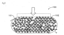
- FIGS. 1 and 2 show the change of a conductive path before and after applying a load in the main body of sensor of the present invention as a model.
- FIGS. 1 and 2 merely show examples of the main body of sensor, so this is not intended to limit a shape, a material and so on of the conductive filler and the main body of sensor of the present invention.
- FIG. 2 shows the no-load state in FIG. 1 ). Since the conductive fillers 102 are blended in the state which is proximate to a closest packing, a space where the conductive fillers 102 can move is hardly present. Therefore, when the main body of sensor 100 is elastically deformed, the conductive fillers 102 are rebounded against each other, and the contact state of the conductive fillers 102 changes. As a result, the three-dimensional conductive paths P break down, and the electric resistance increases.
- the deformation sensor of the present invention having such a main body of sensor can detect a load acting on the target components and portions, and various deformations of the components and portions based on increase and decrease in the electric resistance of the main body of sensor output from an electrode. Since the base material of the main body of sensor is elastomer, it can be elastically deformed. For this reason, the deformation sensor of the present invention can detect various kinds of deformation of components and portions such as a compression, an extension, a bending and so on. The deformation sensor of the present invention has excellent workability and the high degree of freedom in shape design. Therefore, the deformation sensor can detect load and deformations on a wide range of components and portions.
- the types of the elastomer and the conductive fillers, and the filling rate of the conductive fillers are adjusted, so that the electric resistance value in the no-load state can be set within a predetermined range. For this reason, a detectable load, and an elastically deformation range, namely, a detecting range can be enlarged. Since an increase behavior of the electric resistance with respect to the elastic deformation can be adjusted, desired response sensitivity can be realized.
- the deformation sensor of the present invention has high conductivity in the no-load state. That is to say, the deformation sensor of the present invention is brought into a conductive state in the no-load state. For this reason, in the no-load state, the diagnosis of an operation is easier than a sensor with low conductivity (for example, a sensor using conventional pressure sensitive conductive resin). That is to say, in the case where the sensor has low conductivity in a no-load state, it is difficult to determine in the no-load state whether the state is normal or abnormal (for example, disconnection occurs in a circuit). For this reason, it is necessary to daringly apply a comparatively high voltage to the sensor with low conductivity and electrify the sensor.
- the deformation sensor of the present invention has high conductivity in the no-load state. For this reason, it is easy to determine the normal or abnormal state in the no-load state. The diagnosis of the operation is, therefore, easy.
- the main body of sensor is composed of an elastomer composition which essentially contains the elastomer and the conductive fillers, and in a percolation curve which expresses a relationship between a blending amount of the conductive fillers and the electric resistance of the elastomer composition , the blending amount of the conductive fillers at a second polarity change point at which a change of the electric resistance is saturated (saturation volume fraction: ⁇ s) is not less than 35 vol%.
- FIG.' 3 schematically shows a relationship between the blending amount of the conductive fillers and the electric resistance in the elastomer composition. As shown in FIG. 3 , when the conductive fillers 102 are blended into the elastomer 101, the electric resistance of the elastomer composition stays about the same as the electric resistance of the elastomer 101 at first.
- the electric resistance abruptly decreases, thereby causing insulator-conductor transition (first polarity change point).
- the blending amount of the conductive fillers 102 at the first polarity change point is called a critical volume fraction ( ⁇ c).
- ⁇ c critical volume fraction
- the change of the electric resistance becomes small at a certain volume fraction, so that the change of the electric resistance is saturated (second polarity change point).
- the blending amount of the conductive fillers 102 at the second polarity change point is called a saturated volume fraction ( ⁇ s).
- Such a change of the electric resistance is called a percolation curve, and it is considered that the change is caused because a conductive path P1 is formed by the conductive fillers 102 in the elastomer 101.
- the conductive fillers cohere so that an agglomerate is formed for such reasons that a particle diameter of the conductive fillers is small and compatibility between the conductive fillers and the elastomer is not good. In this case, a one-dimensional conductive path is easily formed.
- the critical volume fraction ( ⁇ c) of the elastomer composition is approximately 20 vol% which is comparatively small.
- the saturated volume fraction ( ⁇ s) becomes comparatively small. In other words, when the critical volume fraction ( ⁇ c) and the saturated volume fraction ( ⁇ s) are small, it is difficult that the conductive fillers exist as primary particles, and secondary particles (agglomerate) are easily formed.
- the main body of sensor is composed of the elastomer composition whose saturated volume fraction ( ⁇ s) is not less than 35 vol%. Since the saturated volume fraction ( ⁇ s) is not less than 35 vol% which is large, the conductive fillers exist stably in the elastomer in an approximately single-particle state. The conductive fillers can be, therefore, blended in the state which is proximate to a closest packing.
- the filling rate of the conductive fillers is not less than 30 vol% to not more than 65 vol% in the case'where a total volume of the main body of sensor is 100 vol%.
- the conductive fillers are blended into the elastomer in the state which is proximate to a closest packing. Therefore, the three-dimensional conductive path is easily formed on the main body of sensor by the conductive fillers.
- the conductive fillers are carbon beads.
- the carbon beads have good conductivity, and is comparatively inexpensive. Since the carbon beads have an approximately spherical shape, they can be blended at a high filling rate.
- an average particle diameter of the conductive fillers is not less than 0.05 ⁇ m to not more than 100 ⁇ m. According to this constitution, it is difficult that the conductive fillers cohere, and the conductive fillers easily exist in the primary particle state.
- the average particle diameter means an average particle diameter of the conductive fillers that exist in the primary particle state.
- the elastomer includes one rubber selected from the group consisting of silicone rubber, ethylene-propylene copolymer rubber, natural rubber, styrene-butadiene copolymer rubber, acrylonitrile-butadiene copolymer rubber and acrylic rubber.
- silicone rubber ethylene-propylene copolymer rubber
- natural rubber natural rubber
- styrene-butadiene copolymer rubber acrylonitrile-butadiene copolymer rubber
- acrylic rubber acrylic rubber
- the main body of sensor is elastically bending deformable. According to this constitution, the change of the electric resistance due to the bending deformation can be detected. Furthermore, as compared with a simple compression deformation and a simple extension deformation, a bending deformation can easily obtain large elastic deformation. For this reason, according to this constitution, detecting accuracy becomes high.
- the main body of sensor has an input surface into which a load is input from the outside, and an anti-input surface opposite to the input surface at their back sides, and the restraining component which restrains the elastic deformation on at least one of the input surface and the anti-input surface is arranged on the one surface.
- the elastic deformation on at least one of the input surface and the anti-input surface is restrained by the restraining component.
- a difference between an elastic deformation on the input surface and an elastic deformation on the anti-input surface becomes large.
- the elastic deformation of the entire main body of sensor becomes large, and thus an increase amount of the electric resistance becomes large. That is to say, the load to be input into the input surface and the deformation due to the load are easily detected.
- the main body of sensor has a long shape, and the plurality of electrodes are arranged long a longitudinal direction of the main body of sensor.
- the elastic deformation of the main body of sensor can be effectively output as the increase amount of the electric resistance.
- the main body of sensor has a flat-plate shape, and at least two or more pairs of electrode, where the two electrodes are opposite to each other, are arranged on a peripheral edge of the main body of sensor. Since the main body of sensor has the flat-plate shape, a load and a deformation on a wider area can be detected.
- the arrangement of the electrodes are enabled to be adjusted and the detecting position is enabled to be specified, the application position of the load and the deformation position can be specified.
- the main body of sensor composing the deformation sensor of the present invention has an elastomer and conductive fillers.
- the elastomer is approximately selected from the group consisting of rubber and a thermoplastic elastomer. It is preferable that the elastomer is insulative. Furthermore, when a mixture of the elastomer and the conductive fillers (elastomer composition) is prepared, it is preferable that a saturated volume fraction ( ⁇ s) in a percolation curve is not less than 35 vol%. When the saturated volume fraction ( ⁇ s) is less than 35 vol%, it is difficult to blend the conductive fillers at a high filling rate in an approximately single-particle state.
- an "elastomer composition” requires an elastomer and spherical conductive fillers as an essential ingredient. Namely, it can include a mixture of an elastomer and spherical conductive fillers, or a mixture of an elastomer, spherical conductive fillers and other additives and so on.
- the elastomer whose gel fraction expressed by the following formula (1) is not more than 15% may be used. It is more preferable that the gel fraction is not more than 10%.
- Gel fraction % Wg - Wf / Wf ⁇ 100 [In the formula (1), Wg is a weight of a solvent insoluble (gel comprising the conductive fillers and the elastomer) that is obtained by dissolving an elastomer composition, in which the conductive fillers are mixed with an elastomer, into a good solvent of the elastomer. Wf is a weight of the conductive fillers.
- the good solvent of the elastomer is preferably the one in which a SP value (solubility parameter) between the solvent and the elastomer is close, for example, toluene, tetrahydrofuran, chloroform and so on.
- the gel fraction becomes an indicator of a critical volume fraction ( ⁇ c) in the percolation curve. That is to say, when the critical volume fraction ( ⁇ c) is less than 30 vol%, a lot of elastomer matters which are adsorbed to and combined with the agglomerate of the conductive fillers exist. For this reason, the'gel fraction becomes a comparatively large value. On the contrary, when the critical volume fraction ( ⁇ s) is not less than 30 vol%, the conductive fillers exist in the approximately single-particle state. For this reason, the less number of elastomer matters are adsorbed to and combined with the agglomerate of the conductive fillers, and the gel fraction becomes a comparatively small value of not more than 15%.
- elastomer examples include natural rubber(NR), isoprene rubber (IR), butadiene rubber (BR), acrylonitrile- butadiene copolymer rubber (NBR), styrene-butadiene copolymer rubber (SBR), ethylene-propylene copolymer rubber [ethylene-propylene copolymer (EPM), ethylene-propylene-dieneternary copolymer (EPDM) or the like], butyl rubber (IIR), halogenated butyl rubber (Cl-IIR, Br-IIR or the like), hydrogenated nitrile rubber (H-NBR), chloroprene rubber (CR), acrylic rubber (AR), chlorosulfonatedpolyethylene rubber (CSM), hydrin rubber, silicone rubber, fluorine-contained rubber, urethane rubber, synthetic latex and so on.
- NR natural rubber
- IR isoprene rubber
- BR butadiene rubber
- NBR acrylonitrile- but
- thermoplastic elastomer examples include various thermoplastic elastomers such as styrene elastomer, olefin elastomer, urethane elastomer, polyester elastomer, polyamide elastomer and fluorine elastomer, and their derivatives. One kind of them may be used independently, or two or more kinds of them may be used. Above all, EPDM whose compatibility with the conductive fillers is extremely satisfactory is preferable. NBR and silicone rubber whose compatibility with the conductive fillers is satisfactory are preferable.
- the conductive fillers have a spherical shape.
- the spherical shape includes not only a true spherical shape, an approximately true spherical shape, but also a elliptic spherical shape, an oval spherical shape (the shape in which a pair of opposite hemispheres are connected by a column), a partial spherical shape, a spherical shape in which a radius is different with respect to each part, a droplet shape and so on.
- an aspect ratio of the conductive fillers (a ratio of a long side to a short side) is preferably within a range of not less than 1 to not more than 2.
- the aspect ratio becomes larger than 2
- a one-dimensional conductive path is easily formed by contact between the conductive fillers.
- the above-mentioned saturated volume fraction ( ⁇ s) can be less than 35 vol%. From a viewpoint that a filling state of the conductive fillers in the elastomer is made to the state which is proximate to a closest packing, particles having a true spherical shape or a shape which is extremely close to a true sphere (an approximately true spherical shape) can be adopted as the conductive fillers.
- the conductive fillers are not especially limited only if they are particles having conductivity.
- the particles are fine particles of a carbon material and a metal. Among these, one kind of particles can be used independently, or two kinds of particles can be used together.
- the conductive fillers do not cohere as much as possible and exist in a single-particle state. Therefore, when the conductive fillers are selected, an average particle diameter and the compatibility with the elastomer or the like may be considered.
- the average particle diameter (primary particle) of the conductive fillers is not less than 0.05 ⁇ m to not more than 100 ⁇ m.
- the saturated volume fraction ( ⁇ s) might be less than 35 vol%.
- the average particle diameter is preferably not less than 0.5 ⁇ m, more preferably not less than 1 ⁇ m.
- the average particle diameter is preferably not more than 60 ⁇ m, more preferably not more than 30 ⁇ m.
- the combination of the conductive fillers and the elastomer, and the average particle diameter or the like of the conductive fillers are suitably adjusted, so that the critical volume fraction ( ⁇ c) and the saturated volume fraction ( ⁇ s) can be adjusted within a desired range.
- the value of D90/D10 in a particle size distribution of the conductive fillers is preferably not less than 1 to not more than 30.
- D90 means a particle diameter with which an accumulated weight becomes 90%
- D10 means a particle diameter with which the accumulated weight becomes 10% in a cumulative particle size curve.
- the value of D90/D10 exceeds 30, the particle size distribution becomes broad, so that an increase behavior of the electric resistance according to the elastic deformation of the main body of sensor becomes unstable. Due to this, there is a fear that a detection repeatability decreases. It is more preferable that the value of D90/D10 is not more than 10. When two ormore kinds of particles are used as the conductive fillers, the value of D90/D10 may be not more than 100.
- carbon beads are preferable.
- meso carbon micro beads manufactured by Osaka Gas Chemicals Co., Ltd. [MCMB6-28 (an average particle diameter is approximately 6 ⁇ m), MCMB10-28 (an average particle diameter is approximately 10 ⁇ m) MCMB25-28 (an average particle diameter is approximately 25 ⁇ m)] carbon micro beads manufactured by Nippon Carbon Co., Ltd.
- NICABEADS registered trademark
- ICB NICABEADS
- PC NICABEADS PC
- NICABEADS MC NICABEADS MSB
- ICB0320 an average particle diameter is approximately 3 ⁇ m
- ICB0520 an average particle diameter is approximately 5 ⁇ m
- ICB1020 an average particle diameter is approximately 10 ⁇ m
- PC0720 an average particle diameter is approximately 7 ⁇ m
- MC0520 an average particle diameter is approximately 5 ⁇ m
- carbon beads an average particle diameter is approximately 10 ⁇ m manufactured by NISSHINBO INDUSTRIES, INC. and so on are used.
- the conductive fillers are blended into the elastomer at a high filling rate.
- the conductive fillers are blended at a rate higher than the critical volume fraction ( ⁇ c) in the approximately percolation curve.
- the critical volume fraction ( ⁇ c) is not less than 30 vol%. Not less than 35 vol% is more preferable. It is, therefore, preferable that the filing rate of the conductive fillers is not less than 30 vol% to not more than 65 vol% in the case where the entire volume of the main body of sensor is 100 vol%.
- the filling rate is less than 30 vol%, the conductive fillers cannot be blended in the state which is proximate to a closest packing, so the desired conductivity cannot be exhibited. Moreover, the change of the electric resistance according to the elastic deformation of the main body of sensor becomes slow, and it is difficult to control the increase behavior of the electric resistance. It is more preferable that the filling rate is not less than 35 vol%. On the contrary, when the filling rate exceeds 65 vol%, the blending into the elastomer becomes difficult, thereby deteriorating formability. Further, it is difficult to elastically deform the main body of sensor. Not more than 55 vol% is more preferable.
- additives may be blended in the main body of sensor.
- the additives include a cross-linking agent, a vulcanization accelerator, a vulcanization co-agent, an antioxidant, a plasticizing agent, a softener, a coloring agent and so on.
- conductive fillers of irregular shape for example, needle shape and so on may be blended.
- the main body of sensor can be manufactured in the following procedures. First, additives such as a vulcanization co-agent and a softener and so on are added to the elastomer to be kneaded. Next, the conductive fillers are added and kneaded, and then, a cross-linking agent and a vulcanization accelerator are added to be kneaded, so that an elastomer composition is formed. Next, The elastomer composition is formed into a sheet shape, and it is filled in a metal mold, and is subjected to a press vulcanization under the predetermined condition.
- additives such as a vulcanization co-agent and a softener and so on are added to the elastomer to be kneaded.
- the conductive fillers are added and kneaded, and then, a cross-linking agent and a vulcanization accelerator are added to be kneaded, so that an elastomer composition is formed
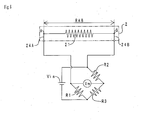
- FIG. 4 is a front view of the deformation sensor.
- FIG. 5 is a V-V cross sectional view of FIG. 4 .
- a conductive wire is omitted.
- the deformation sensor 2 has an electrode film section 20, a main body of sensor 21, and a restraining film section 22.
- the electrode film section 20 has a base material film 200 and a cover film 201.
- the base material film 200 is made of polyimide and has a band shape which extends to a right-left direction.
- the base material film 200 is fixed to a surface of a base material 900.
- a connector 23 is mounted to a right end of the base material film 200.
- the cover film 201 is made of polyimide, and has a band shape which extends to a right-left direction.
- the cover film 201 covers the surface of the base material film 200.
- a long hole 201a which extends to a right-left direction and corresponds to the main body of sensor 21 is provided to a center of a widthwise direction (up-down direction) of the cover film 201.
- the main body of sensor 21 has a long plate shape which extends to a right-left direction.
- the main body of sensor 21 is fixed to the surface of the base material film 200 in a state that the main body of sensor 21 is housed in the long hole 201a of the cover film 201.
- a contact surface of the main body of sensor 21 with the base material film 200 becomes an input surface into which a load is input.
- the main body of sensor 21 is composed of an elastomer composite material in which carbon beads ("NICABEADS ICB0520" manufactured by Nippon Carbon Co., Ltd.; an average particle diameter is approximately 5 ⁇ m) are blended into EPDM.
- the filling rate of the carbon beads is 48 vol% in the case where the volume of the main body of sensor 21 is 100 vol%.
- the critical volume fraction ( ⁇ c) is 43 vol%
- the saturated volume fraction ( ⁇ s) is 48 vol%.
- An electrode A is mounted to a left end of the main body of sensor 21, and an electrode B is mounted to a right end. More specifically, the electrodes A and B have a strip shape which extends up and down, and are laid between the main body of sensor 21 and the base material film 200, and between the cover film 201 and the base material film 200, respectively.
- the electrode A and a connector 23 are connected by a conductive wire 24A, and the electrode B and the connector 23 are connected by a conductive wire 24B, respectively.
- the restraining film section 22 is made of polyimide and has a band shape which extends to a right-left direction.
- the restraining film section 22 is fixed to the surface (rear surface) of the main body of sensor 21 opposite to the base materialfilm200.
- the contact surface of the main body of sensor 21 with the restraining film section 22 is an anti-input surface.
- the base material film 200 and the restraining film section 22 are included in a restraining component of the present invention.
- FIG. 6 shows a pattern diagram of the circuit.
- the main body of sensor 21 is connected to a Wheatstone bridge circuit via the conductive wire 24A connected to the electrode A and the conductive wire 24B connected to the electrode B.
- a voltage of a power source Vin, and electric resistances of the resistors R1, R2 and R3 are already known.
- a voltage value of a voltmeter Vm is measured, so that the electric resistance of the main body of sensor 21 can be measured.
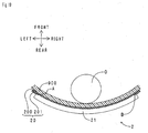
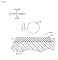
- FIG. 7 is a cross-section view when viewed from above the deformation sensor (before crash, corresponding to a cross-section view taken along line VII-VII of FIG. 4 ).
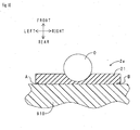
- FIG. 8 is a cross-section view when viewed from above the deformation sensor after crash.
- the crash direction of the object to crash O is a front-rear direction.
- the object to crash O crashes against the base material 900 at a front, the base material 900 is deformed so as to subside backward.
- the deformation of the base material 900 is transmitted to the main body of sensor 21 via the base material film 200.
- the main body of sensor 21 is curved elastically into a C shape where it is opened on a front side.
- a before-crash state shown in FIG. 7 , as shown in FIG. 1 , the main body of sensor is filled with the conductive fillers 102 in a state which is proximate to a closest packing. For this reason, a lot of conductive paths P are formed. Therefore, the electric resistance between the electrodes A and B detected by the circuit in FIG. 6 is comparatively low.
- the conductive fillers 102 are rebound against each other. For this reason, the conductive paths P break down. Therefore, the electric resistance between the electrodes A and B detected by the circuit in FIG. 6 becomes higher than the electric resistance in the before-crash state.
- the restraining filmsection 22 is fixed to the surface (rear surface) of the main body of sensor 21. For this reason, an extension deformation near the rear surface of the main body of sensor 21 due to crash is restrained by the restraining film section 22. Concretely, as shown by a dotted line in FIG. 8 , the restraining film 22 controls the extension deformation near the rear surface of the main body of sensor 21, and the main body of sensor 21 is subjected to shearing deformation. When both the surfaces of the main body of sensor 21 are restrained, concentration of large strain can be induced, thereby further increasing the electric resistance between the electrodes A and B.
- the deformation sensor 2 of the first embodiment is in an undeformed free state and in a conductive state. Therefore, an electric current is applied to the circuit into which the deformation sensor 2 is incorporated, thereby easily conducting a self diagnosis as to whether the deformation sensor 2 is operable.
- a different point of the deformation sensor in the second embodiment from the deformation sensor in the first embodiment is that the restraining film section is not arranged on the rear surface of the main body of sensor. Therefore, here, only the different point is described below.
- FIG. 9 is a cross-section view when viewed from above the deformation sensor according to the second embodiment before crash. By the way, Portions corresponding to those in FIG. 7 are indicated as the same symbols.
- FIG. 10 is a cross-section view when viewed from above the deformation sensor in the second embodiment after crash. Portions corresponding to those in FIG. 8 are indicated as the same symbols.
- the restraining film section 22 is not arranged on the surface (rear surface) of the main body of sensor 21 opposite to the base material film 200.
- the base material 900 is deformed so as to subside to the rear side.
- the deformation of the base material 900 is transmitted to the main body of sensor 21 via the base material film 200.
- the main body of sensor 21 is elastically curved into a C shape where it is opened to the front side.
- the restraining film section is not arranged on the back surface of the main body of sensor 21.
- the extension deformation near the back surface of the main body of sensor 21 is not controlled (the main body of sensor 21 is deformed up to a dotted-line portion in FIG. 8 ).
- the increase in the electric resistance based on the extension deformation is predominant.
- the deformation sensor of this preferred embodiment has the same action and effect as those of the deformation sensor of the first preferred embodiment. Furthermore, according to the deformation sensor 2 of the second embodiment, since the restraining film section is not arranged, the constitution becomes simple, thereby repressing the manufacturing cost.
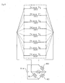
- a different point of the deformation sensor in the third embodiment from the deformation sensor in the first embodiment is that four electrodes are arranged on the main body of sensor. Therefore, here, only the different point is described below.
- FIG. 11 shows a front view of the deformation sensor according to the third embodiment.
- the restraining film section is omitted. Portions corresponding to those in FIG. 4 are indicated as the same symbols.
- four electrodes a to d are arranged on the main body of sensor 21 so as to be separated by predetermined intervals in the right-left direction.
- the electrodes a to d and the connector 23 are connected by conductive wires 24a to 24d, respectively.
- the main body of sensor 21 is divided into three zones 210, 211 and 212 by the electrodes a to d.
- FIG. 12 is a pattern diagram of a circuit into which the deformation sensor of the third embodiment is incorporated. Portions corresponding to those in FIG. 6 are indicated as the same symbols.
- a resistor Rab in the zone 210 between the electrodes a and b, a resistor Rbc in the zone 211 between the electrode b and c, and a resistor Rcd in the zone 212 between the electrodes c and d are switched so as to be sequentially connected to the Wheatstone bridge circuit. For this reason, a change of the electric resistances of the resistors Rab, Rbc and Rcd is repeatedly output.
- the deformation sensor 2 of the third embodiment has the same action and effect as those of the deformation sensor of the first preferred embodiment. Furthermore, according to the deformation sensor 2 of the third embodiment, the four electrodes are arranged so as to divide the main body of sensor 21 in the right-left direction. For this reason, even in a deformation in a small area, an increase in the electric resistance is securely output, so that crash or the like can be determined accurately. The increase in the electric resistance in each area is input, so that a deformed position can be easily specified.
- a different point of the deformation sensor in the fourth embodiment from the deformation sensor in the first embodiment is that the main body of sensor has a flat-plate shape. And, the deformation sensor is included in a component, and the restraining film section is not arranged on the surface of the main body of sensor. Therefore, here, only the different point is described below.
- FIG. 13 is a front view of the deformation sensor according to the fourth embodiment. Portions corresponding to those in FIG. 4 are indicated as the same symbols.
- the deformation sensor 2 has a quadrate shape.
- the deformation sensor 2 is included in the component (not shown).
- the main body of sensor 21 has a quadrate flat-plate shape. Electrodes Xa to Xh and Ya to Yh are arranged on four sides of the main body of sensor 21.
- the electrodes Xa and Xe, the electrodes Xb and Xf, the electrodes Xc and Xg, the electrodes Xd and Xh, the electrodes Ya and Ye, the electrodes Yb and Yf, the electrodes Yc and Yg and the electrodes Yd and Yh are arranged so as to be opposite to each other.
- FIG. 14 is a pattern diagram of a circuit into which the deformation sensor of the fourth embodiment is incorporated. Portions corresponding to those in FIG. 6 are indicated as the same symbols.
- the electrodes Xa and Xe, the electrodes Xb and Xf, the electrodes Xc and Xg, the electrodes Xd and Xh, the electrodes Ya and Ye, the electrodes Yb and Yf, the electrodes Yc and Yg and the electrodes Yd and Yh are switched so as to be sequentially connected to the Wheatstone bridge circuit. For this reason, changes in the electric resistances between the above electrodes are repeatedly output.
- the deformation sensor 2 of the fourth embodiment has the same action and effect as those of the deformation sensor of the first preferred embodiment. Furthermore, according to the deformation sensor 2 of the fourth embodiment, a position to which the load is applied and scale of the load can be determined precisely based on the changes in the electric resistances. According to the deformation sensor 2 of the fourth embodiment, the electrodes Xa to Xh, and Ya to Yh are arranged on an outer periphery (four sides) of the main body of sensor 21. That is to say, since the electrodes are not arranged on an area to which the load is applied, durability of the deformation sensor 2 in the fourth embodiment is high.
- the deformation sensor according to the embodiments of the present invention is described above.
- the deformation sensor of the present invention is not limited to the above embodiments.
- the present invention can be embodied in various modified forms and improved forms which can be made by a person skilled in the art.
- the deformation sensor of the present invention is used for indirectly detecting the load, but may be used for directly detecting the load.
- FIG. 15 is a cross-section view when viewed from above the deformation sensor capable of directly detecting the load (the before-crash state). Portions corresponding to those in FIG. 7 are indicated as the same symbols.
- the deformation sensor 2a has the main body of sensor 21, the electrodes A and B, and the base material 910.
- the main body of sensor 21 is fixed to the front surface of the base material 910.
- the base material 910 is included in the restraining component of the present invention.
- the deformation sensor 2a is arranged directly on a position where the obj ect to crash O crashes against the main body of sensor 21.
- FIG. 16 is a cross-section view when viewed from above the deformation sensor after crash. As shown in FIG. 16 , when the object to crash O crashes, the front surface (front surface of the main body of sensor 21) of the deformation sensor 2a subsides, and the main body of sensor 21 is compressed and deformed.
- the electric resistance between the electrodes A and B changes. Presence/non-presence of crash, and the load can be detected based on the change of the electric resistance.
- the load may be input from the object to crash O directly to the deformation sensor 2a without the base material 900 and the base material film 200, as shown in FIG. 8 .
- the main body of sensor 21 is fixed directly to the front surface of the base material 910.
- the base material 910 on which the main body of sensor 21 is arranged may be used as the restraining component.
- a weather-proof cover may be arranged so as to cover at least a part of the main body of sensor. This suppresses deterioration of the main body of sensor, and improves the durability.
- the base material film and the restraining film section (restraining component) or the like are made of polyimide (PI).
- the polyimide has a high insulating property and is used a lot for FPC (flexible print circuit board) or the like.
- the material of the restraining component is not limited to this.
- the restraining component are resin films of polyethylene (PE), polyethylene terephthalate (PET) or the like, and a metal plate such as high damping steel.
- the base material film which fixes the main body of sensor may be a single layer like the above embodiments, or may be a multiple layer obtained by laminating a plurality of films.
- the electrodes and the main body of sensor may be bonded by cure adhesion. As a result, the electrodes can be arranged simultaneously with the vulcanization of the main body of sensor.
- the method for detecting the electric resistance is not particularly limited. Temperature may be compensated or a signal may be amplified suitably.
- the deformation sensor of the present invention can be applied to various applications such as a vehicle crash detecting sensor, a crew detecting sensor, an artificial skin touch sensor, a human body' s joint sensor, a bed surface pressure distribution sensor, a drawing tablet sensor, and a window glass breakage detecting sensor.
- the sample (deformation sensor) 2 has the electrode film section 20 and the main body of sensor 21, and its entire shape is a band shape.
- the main body of sensor 21 is produced in the following procedures.
- parts 85 parts by weight (hereinafter, referred to as "parts” for short) (85g) of an oil extension EPDM ("ESPRENE (registration of trade mark) 6101" manufactured by Sumitomo Chemical Co., Ltd.), 34 parts (34g) of an oil extension EPDM ("ESPRENE 601" manufactured by Sumitomo Chemical Co., Ltd.), 30 parts (30g) of EPDM ( "ESPRENE 505" manufactured by Sumitomo Chemical Co., Ltd.), 5 parts (5g) of two kinds of zinc oxide (manufactured by Hakusui Chemical Industry Co., Ltd.), 1 parts (1g) of stearic acid ( "LUNAC (registration of trade mark) S30 " manufactured by Kao Corporation) and 20 parts (20g) of a paraffinic process oil ( "SUNPAR (registration of trade mark) 110" manufactured by Japan Sun Oil Company, Ltd.) were kneaded by a roll kneader.
- ESPRENE registration of trade mark 6101 manufactured by
- the volume fraction of the carbon beads in the prepared elastomer composition is approximately 48 vol% when a total volume of the elastomer composition is 100 vol%. Furthermore, the critical volume fraction ( ⁇ c) of the elastomer composition in a percolation curve is approximately 43 vol%, and the saturated volume fraction ( ⁇ s) is approximately 48 vol%. Moreover, when the elastomer composition was dissolved into a solvent (toluene) and the solvent insoluble was measured, the gel fraction is approximately 3%.
- the elastomer composition was formed into a band shape of predetermined size so that a compact is formed.
- a metal mold was filled with the compact, and an electrode was arranged on a predetermined position.
- a press vulcanization was carried out at 170°C for 30 minutes to obtain a main body of sensor 21.
- the filling rate of the carbon beads in the obtained main body of sensor 21 is approximately 48 vol% when a total volume of the main body of sensor 21 is 100 vol%.
- the sample of the main body of sensor 21 with thickness of 2 mm, width of 10 mm and length of 50 mm is an example 1
- the sample with the same thickness and width as those in the example 1 and with length of 100 mm is an example 2.
- the sample with the same thickness and width as those in the example 1 and with length of 150 mm is an example 3
- the sample with the same thickness and width as those in the example 1 and length of 300 mm is an example 4.
- the electrodes A and B are arranged on both ends of the main body of sensor 21 in the longitudinal direction, respectively.
- the electrodes A and B are arranged on both the ends in the longitudinal direction, five electrodes C, D, E, F and G are arranged in the longitudinal direction at equal intervals. That is to say, the seven electrodes A to G are arranged on the sample of the example 4 so that a distance between the adjacent electrodes is 50 mm.
- FIG. 17 is a pattern diagram for showing an experiment apparatus.
- the experiment apparatus 4 has an upper end holder 40, a lower end holder 41, a vibration jig 42, and a laser displacement sensor 43.
- the upper end holder 40 is unmovable, and grips one end (upper end) of the sample (deformation sensor) 2 in the longitudinal direction.
- the lower end holder 41 is arranged so as to be separated downward from the upper end holder 40.
- the lower end holder 41 is fixed to the vibration jig 42.
- the vibration jig 42 can be repeatedly moved to an up-down direction.
- the lower end holder 41 grips the other end (lower end) of the sample 2 in the longitudinal direction.
- the vibration jig 42 When the vibration jig 42 is moved to the up-down direction, the interval between the upper holder 40 and the lower end holder 41 contracts and is enlarged. As a result, the sample 2 is curved. The deformation of the sample 2 is measured by the laser displacement sensor 43. The electric resistance of the sample 2 is output from the electrodes A and B to an external circuit (not shown). The samples of the examples 1 to 4 are periodically bent (vibration frequency: 1 Hz, 3 Hz), and a change of the electric resistance is measured.
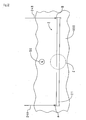
- FIG. 18 shows a method for defining a curvature in this experiment.
- a length in a linear state (dotted line) of the main body of sensor 21 is designated by L
- a projected length of the linear state in a curved state is designated by L1
- a difference between L and L1 is a bend-strain distance S.
- the curvature (%) is defined as S (mm) / L1 (mm) x 100.
- FIG. 19 shows a change of an electric resistance ( ⁇ R) according to a bend-strain distance (S) in each sample. As shown in FIG. 19 , in any samples, the electric resistance increases due to the bending deformation.
- FIG. 20 shows a change of an electric resistance ( ⁇ R) according to a curvature in each sample. As shown in FIG. 20 , in any samples the curvature is large, namely, as the curve deformation is larger, the change of the electric resistance becomes larger.
- the sample of the example 2 is bent with the vibration frequency being varied, and the change of the electric resistance is measured.
- FIG. 21 shows a change of an electric resistance ( ⁇ R) according to a bend-strain distance (S) in the case where the vibration frequency is varied. As shown in FIG. 21 , even if the vibration frequency is varied, the change of the electric resistance is almost uniform.
- the main body of sensor 21 produced in the experiment (1) (thickness: 2 mm, width: 5 mm, length: 100 mm) is used.
- the main body of sensor 21 is mounted to the rear surface of the base material so that the deformation sensor is constituted, and the responsiveness of the deformation sensor to the impact from the surface of the base material is evaluated.
- FIG. 22 is an arrangement diagram of the deformation sensor.
- the deformation sensor 2 has the main body of sensor 21, the electrodes A and B, and the base material 900.
- the main body of sensor 21 is fixed to the rear surface of the base material 900.
- the contact surface of the main body of sensor 21 with the base material 900 is an input surface into which the load is input.
- the base material 900 is included in the restraining component of the present invention.
- the electrode A is mounted to the left end of the main body of sensor 21, and the electrode B is mounted to the right end of the main body of sensor 21.
- the main body of sensor 21 is connected to the external circuit (not shown, see FIG. 6 ) via the electrode A, the conductive wire 24A, the electrode B and the conductive wire 24B.
- An acceleration sensor 50 is arranged on the rear surface of the base material 900.
- the acceleration sensor 50 is arranged near a center of the deformation sensor 2 in the longitudinal direction so as to be separated from the deformation sensor 2.
- the base material 900 When a impact is applied to the base material 900 from a sheet rear surface side of a sheet, the base material 900 is deformed, and accordingly the deformation sensor 2 is deformed.
- the deformation of the deformation sensor 2 is measured by the laser displacement sensor (not shown).
- the electric resistance value of the deformation sensor 2 is output from the electrodes A and B to the external circuit (not shown).
- the magnitude of acceleration at impact is measured by the acceleration sensor 50.
- a impact is applied to the surface of the base material 900 (the rear surface side of the sheet) by hitting it with a fist (high-speed impact).
- a impact input position is designated by a dotted line circle Z.
- the magnitude of acceleration at impact, the displacement of the deformation sensor 2 due to the impact, and the electric resistance value are measured.
- an impact is applied to the surface of the base material 900 (the rear surface side of the sheet) by pressurizing it with a palm (low-speed impact).
- the impact input position is similar to the above one. At this time, the magnitude of acceleration at impact, the displacement of the deformation sensor 2 due to the impact, and the electric resistance value are measured.
- FIGS. 23 to 25 show The experiment results.
- FIG. 23 shows a change over time of an acceleration of a high-speed impact, a displacement of the deformation sensor and an electric resistance value.
- FIG. 24 shows an enlargement of a horizontal axis (time: 65-85ms) of FIG. 23 .
- the electric resistance value of the deformation sensor promptly increases according to the high-speed impact.
- the responsiveness of the deformation sensor of the present invention is high.
- the electric resistance value changes in proportional to the bending deformation of the deformation sensor. That is to say, the deformation sensor of the present invention can directly detect the bending deformation.
- FIG. 25 shows a change over time of an acceleration of a low-speed impact, a displacement of the deformation sensor and an electric resistance value in the second experiment.
- the acceleration is not generated.
- the electric resistance value changes in proportional to the bending deformation of the deformation sensor.
- the deformation sensor of the present invention can detect the bending deformation even in the case of the low-speed impact.
Applications Claiming Priority (1)
| Application Number | Priority Date | Filing Date | Title |
|---|---|---|---|
| JP2006251386A JP5568206B2 (ja) | 2006-09-15 | 2006-09-15 | 変形センサ |
Publications (3)
| Publication Number | Publication Date |
|---|---|
| EP1901048A2 EP1901048A2 (en) | 2008-03-19 |
| EP1901048A3 EP1901048A3 (en) | 2009-03-25 |
| EP1901048B1 true EP1901048B1 (en) | 2012-07-18 |
Family
ID=38826560
Family Applications (1)
| Application Number | Title | Priority Date | Filing Date |
|---|---|---|---|
| EP07017670A Not-in-force EP1901048B1 (en) | 2006-09-15 | 2007-09-10 | Deformation sensor |
Country Status (3)
| Country | Link |
|---|---|
| US (1) | US7703333B2 (ja) |
| EP (1) | EP1901048B1 (ja) |
| JP (1) | JP5568206B2 (ja) |
Families Citing this family (47)
| Publication number | Priority date | Publication date | Assignee | Title |
|---|---|---|---|---|
| JP5166714B2 (ja) * | 2006-09-15 | 2013-03-21 | 東海ゴム工業株式会社 | センサー用架橋エラストマー体およびその製法 |
| JP5420819B2 (ja) * | 2006-10-25 | 2014-02-19 | 東海ゴム工業株式会社 | 衝撃センサ |
| US7411338B1 (en) * | 2007-01-30 | 2008-08-12 | Raytheon Company | Structural material with piezoelectric material particles |
| US8272278B2 (en) | 2007-03-28 | 2012-09-25 | University Of Southern California | Enhancements to improve the function of a biomimetic tactile sensor |
| WO2009023334A2 (en) | 2007-05-18 | 2009-02-19 | University Of Southern California | Biomimetic tactile sensor for control of grip |
| JP4368392B2 (ja) * | 2007-06-13 | 2009-11-18 | 東海ゴム工業株式会社 | 変形センサシステム |
| JP5496446B2 (ja) * | 2007-07-12 | 2014-05-21 | 東海ゴム工業株式会社 | 静電容量型センサ |
| US8230600B2 (en) * | 2007-09-17 | 2012-07-31 | The Gillette Company | Cartridge detachment sensor |
| US8161826B1 (en) * | 2009-03-05 | 2012-04-24 | Stryker Corporation | Elastically stretchable fabric force sensor arrays and methods of making |
| US7958789B2 (en) * | 2008-08-08 | 2011-06-14 | Tokai Rubber Industries, Ltd. | Capacitive sensor |
| JP5662636B2 (ja) * | 2008-08-27 | 2015-02-04 | 住友理工株式会社 | 荷重センサ |
| JP5662637B2 (ja) * | 2008-08-27 | 2015-02-04 | 住友理工株式会社 | 荷重センサ |
| US7891260B2 (en) * | 2009-02-05 | 2011-02-22 | Delphi Technologies, Inc. | Seat sensor apparatus for occupant presence detection |
| JP5257896B2 (ja) * | 2009-05-22 | 2013-08-07 | 国立大学法人電気通信大学 | 滑り検出装置及び方法 |
| JP2011058951A (ja) * | 2009-09-09 | 2011-03-24 | Tokai Rubber Ind Ltd | センサユニットおよびその取付方法 |
| JP5654789B2 (ja) * | 2009-11-24 | 2015-01-14 | 住友理工株式会社 | 曲げセンサおよび変形形状測定方法 |
| WO2011065100A1 (ja) | 2009-11-24 | 2011-06-03 | 東海ゴム工業株式会社 | 曲げセンサおよび変形形状測定方法 |
| JP5486683B2 (ja) * | 2010-11-04 | 2014-05-07 | 東海ゴム工業株式会社 | 曲げセンサ |
| KR101206566B1 (ko) | 2010-11-11 | 2012-11-29 | 국립대학법인 울산과학기술대학교 산학협력단 | 나노 복합체 스트레인 측정장치 및 이를 이용한 스트레인 측정방법 |
| WO2012073770A1 (ja) * | 2010-11-30 | 2012-06-07 | 東海ゴム工業株式会社 | 蓄電デバイス |
| JP5728305B2 (ja) * | 2011-06-21 | 2015-06-03 | 住友理工株式会社 | 変形センサシステム |
| TW201348685A (zh) * | 2012-05-24 | 2013-12-01 | Dmp Electronics Inc | 壓力感測器 |
| US10716510B2 (en) | 2013-09-17 | 2020-07-21 | Medibotics | Smart clothing with converging/diverging bend or stretch sensors for measuring body motion or configuration |
| US10602965B2 (en) | 2013-09-17 | 2020-03-31 | Medibotics | Wearable deformable conductive sensors for human motion capture including trans-joint pitch, yaw, and roll |
| US10321873B2 (en) | 2013-09-17 | 2019-06-18 | Medibotics Llc | Smart clothing for ambulatory human motion capture |
| US9582072B2 (en) | 2013-09-17 | 2017-02-28 | Medibotics Llc | Motion recognition clothing [TM] with flexible electromagnetic, light, or sonic energy pathways |
| US9588582B2 (en) | 2013-09-17 | 2017-03-07 | Medibotics Llc | Motion recognition clothing (TM) with two different sets of tubes spanning a body joint |
| KR101971945B1 (ko) * | 2012-07-06 | 2019-04-25 | 삼성전자주식회사 | 촉각 측정 장치 및 방법 |
| KR102104588B1 (ko) * | 2012-07-11 | 2020-04-24 | 삼성전자주식회사 | 플렉서블 디스플레이 장치 및 그 동작 방법 |
| US9043004B2 (en) * | 2012-12-13 | 2015-05-26 | Nike, Inc. | Apparel having sensor system |
| NZ711183A (en) * | 2013-03-15 | 2019-12-20 | Nano Composite Products Inc | Composite material used as a strain gauge |
| US10260968B2 (en) | 2013-03-15 | 2019-04-16 | Nano Composite Products, Inc. | Polymeric foam deformation gauge |
| EP2829857A1 (en) * | 2013-07-24 | 2015-01-28 | Ecole Polytechnique | Piezoresistive material exhibiting an optimal gauge factor |
| US20150122531A1 (en) * | 2013-11-01 | 2015-05-07 | Carestream Health, Inc. | Strain gauge |
| GB201408833D0 (en) | 2014-05-19 | 2014-07-02 | Skoogmusic Ltd | Control apparatus |
| US9857246B2 (en) | 2014-09-17 | 2018-01-02 | Sensable Technologies, Llc | Sensing system including a sensing membrane |
| JP6448084B2 (ja) * | 2014-12-10 | 2019-01-09 | 国立大学法人福島大学 | 位置検出システム |
| US10405779B2 (en) | 2015-01-07 | 2019-09-10 | Nano Composite Products, Inc. | Shoe-based analysis system |
| US10672530B2 (en) | 2016-02-29 | 2020-06-02 | Liquid Wire Inc. | Deformable conductors and related sensors, antennas and multiplexed systems |
| US11156509B2 (en) | 2016-02-29 | 2021-10-26 | Liquid Wire Inc. | Sensors with deformable conductors and selective deformation |
| JP6772539B2 (ja) * | 2016-05-16 | 2020-10-21 | 住友ゴム工業株式会社 | タイヤ用ゴム組成物の製造方法及びタイヤ用ゴム組成物 |
| KR101753247B1 (ko) * | 2016-06-30 | 2017-07-04 | 엘지이노텍 주식회사 | 압력 감지 센서 및 이를 포함하는 압력 감지 장치 |
| EP3781895A4 (en) * | 2018-04-20 | 2022-01-26 | Direct-C Limited | WIDE RANGE SENSORS |
| WO2020017013A1 (ja) * | 2018-07-19 | 2020-01-23 | Posh Wellness Laboratory株式会社 | 検出装置、シートベルト、及び運転手監視システム |
| CN112956283A (zh) | 2018-08-22 | 2021-06-11 | 液态电线公司 | 具有可变形导体的结构 |
| WO2020247697A1 (en) | 2019-06-05 | 2020-12-10 | Liquid Wire Inc. | Deformable sensors with selective restraint |
| CN112179561B (zh) * | 2020-09-17 | 2022-09-30 | 五邑大学 | 一种压力传感器阵列定标方法、装置及设备 |
Family Cites Families (30)
| Publication number | Priority date | Publication date | Assignee | Title |
|---|---|---|---|---|
| US3806471A (en) | 1968-04-29 | 1974-04-23 | R Mitchell | Pressure responsive resistive material |
| US3814998A (en) * | 1973-05-18 | 1974-06-04 | Johnson Service Co | Pressure sensitive capacitance sensing element |
| JPS588563B2 (ja) * | 1974-06-14 | 1983-02-16 | カブシキガイシヤ イノウエジヤパツクスケンキユウジヨ | カンアツテイコウタイ |
| US4347505A (en) | 1979-01-29 | 1982-08-31 | Antroy Enterprises, Inc. | Device for controlling a circuit |
| JPS58209810A (ja) * | 1982-05-31 | 1983-12-06 | 横浜ゴム株式会社 | 感圧型導電性エラストマ−シ−トおよびその製造方法 |
| US4503416A (en) | 1982-12-13 | 1985-03-05 | General Electric Company | Graphite fiber tactile sensor |
| JPS6212825A (ja) * | 1985-07-10 | 1987-01-21 | Shinei Kk | 感力センサ−とその測定装置 |
| ATE103095T1 (de) * | 1986-01-14 | 1994-04-15 | Raychem Corp | Leitfaehige polymerzusammensetzung. |
| SE459827B (sv) | 1987-11-20 | 1989-08-07 | Labino Patent Ab | Tryckkaenslig potentiometer |
| JPH0779006B2 (ja) * | 1989-09-04 | 1995-08-23 | イナバゴム株式会社 | 感圧導電性エラストマー |
| US5090246A (en) * | 1990-09-19 | 1992-02-25 | Johnson Service Corp. | Elastomer type low pressure sensor |
| JPH04147024A (ja) * | 1990-10-09 | 1992-05-20 | Alps Electric Co Ltd | 変位センサならびにこの変位センサを使用した検知装置 |
| JPH076853B2 (ja) * | 1991-04-19 | 1995-01-30 | イナバゴム株式会社 | 方向圧力感知センサー |
| JP2676057B2 (ja) * | 1991-09-24 | 1997-11-12 | イナバゴム 株式会社 | 触覚センサー |
| US5571973A (en) * | 1994-06-06 | 1996-11-05 | Taylot; Geoffrey L. | Multi-directional piezoresistive shear and normal force sensors for hospital mattresses and seat cushions |
| JPH08159853A (ja) * | 1994-11-30 | 1996-06-21 | Sumitomo Rubber Ind Ltd | 車両の重量検出装置 |
| JPH095014A (ja) | 1995-06-19 | 1997-01-10 | Hirano Denshi:Kk | 曲げセンサ |
| JP3200682B2 (ja) | 1995-12-11 | 2001-08-20 | トーヨーポリマー株式会社 | 変形量検知装置 |
| US6073497A (en) * | 1997-08-05 | 2000-06-13 | Micron Technology, Inc. | High resolution pressure sensing device having an insulating flexible matrix loaded with filler particles |
| JP4655252B2 (ja) * | 1999-04-15 | 2011-03-23 | 新原 ▲晧▼一 | 変形導電性エラストマーの製造方法 |
| US6664006B1 (en) * | 1999-09-02 | 2003-12-16 | Lithium Power Technologies, Inc. | All-solid-state electrochemical device and method of manufacturing |
| JP2003329520A (ja) * | 2002-05-08 | 2003-11-19 | Kinmirai Technos:Kk | 加圧センサ |
| JP3986985B2 (ja) * | 2003-03-25 | 2007-10-03 | 株式会社デンソー | 感圧抵抗体及び感圧センサ |
| JP3727642B1 (ja) * | 2004-08-24 | 2005-12-14 | 賢一 森元 | 触覚センサ及び触覚センサ応用装置 |
| EP1806568A1 (en) * | 2004-10-28 | 2007-07-11 | Matsushita Electric Industrial Co., Ltd. | Piezoelectric element and method for manufacturing the same |
| US7260999B2 (en) * | 2004-12-23 | 2007-08-28 | 3M Innovative Properties Company | Force sensing membrane |
| JP2006226742A (ja) * | 2005-02-16 | 2006-08-31 | Iom Kk | 加重分布検知シート及び加重分布の検知表示システム |
| EP1916529B1 (en) * | 2006-10-25 | 2011-03-16 | Tokai Rubber Industries, Ltd. | Deformation sensor |
| JP4368392B2 (ja) * | 2007-06-13 | 2009-11-18 | 東海ゴム工業株式会社 | 変形センサシステム |
| JP5496446B2 (ja) * | 2007-07-12 | 2014-05-21 | 東海ゴム工業株式会社 | 静電容量型センサ |
-
2006
- 2006-09-15 JP JP2006251386A patent/JP5568206B2/ja not_active Expired - Fee Related
-
2007
- 2007-09-06 US US11/896,904 patent/US7703333B2/en not_active Expired - Fee Related
- 2007-09-10 EP EP07017670A patent/EP1901048B1/en not_active Not-in-force
Also Published As
| Publication number | Publication date |
|---|---|
| EP1901048A3 (en) | 2009-03-25 |
| JP2008070327A (ja) | 2008-03-27 |
| US20080066564A1 (en) | 2008-03-20 |
| JP5568206B2 (ja) | 2014-08-06 |
| EP1901048A2 (en) | 2008-03-19 |
| US7703333B2 (en) | 2010-04-27 |
Similar Documents
| Publication | Publication Date | Title |
|---|---|---|
| EP1901048B1 (en) | Deformation sensor | |
| EP1901311B1 (en) | Crosslinked elastomer body | |
| EP2015043B1 (en) | Electrostatic capacity-type sensor | |
| US6529122B1 (en) | Tactile sensor apparatus and methods | |
| US9645028B2 (en) | Resistive pressure sensor including piezo-resistive electrode | |
| JP5486683B2 (ja) | 曲げセンサ | |
| EP2381233B1 (en) | Bend sensor and method of measuring deformed shape | |
| US5652395A (en) | Bending sensor | |
| JP4368392B2 (ja) | 変形センサシステム | |
| JP2009527765A (ja) | 容量タッチパッド技術を用いて、ロボット把持メカニズムに接触感覚を得させるシステム | |
| CN110987031B (zh) | 一种柔性触觉传感器 | |
| WO2017057598A1 (ja) | 静電容量型センサ | |
| JP2008197060A (ja) | 変形センサシステム | |
| JP5302501B2 (ja) | 車両の外装部材変形センサ | |
| CN111595505B (zh) | 轴向力传感器组件、机器人夹爪及机器人 | |
| JP2008102090A (ja) | 変形センサシステム | |
| KR101479709B1 (ko) | 접촉정보 측정센서 및 접촉정보 측정방법 | |
| JP2008102089A (ja) | 変形センサシステム | |
| JP5420819B2 (ja) | 衝撃センサ | |
| JP6082856B1 (ja) | 静電容量型センサ | |
| JP2009276183A (ja) | センサ用複合材料および変形センサ | |
| US20220305666A1 (en) | Axial force sensor assembly, robot gripper and robot | |
| JP2015200501A (ja) | 歪み計測装置、歪み量及び歪み方向計測方法 | |
| JP2008241528A (ja) | 変形センサシステム | |
| JP2008286747A (ja) | 変形センサシステム |
Legal Events
| Date | Code | Title | Description |
|---|---|---|---|
| PUAI | Public reference made under article 153(3) epc to a published international application that has entered the european phase |
Free format text: ORIGINAL CODE: 0009012 |
|
| AK | Designated contracting states |
Kind code of ref document: A2 Designated state(s): AT BE BG CH CY CZ DE DK EE ES FI FR GB GR HU IE IS IT LI LT LU LV MC MT NL PL PT RO SE SI SK TR |
|
| AX | Request for extension of the european patent |
Extension state: AL BA HR MK YU |
|
| PUAL | Search report despatched |
Free format text: ORIGINAL CODE: 0009013 |
|
| AK | Designated contracting states |
Kind code of ref document: A3 Designated state(s): AT BE BG CH CY CZ DE DK EE ES FI FR GB GR HU IE IS IT LI LT LU LV MC MT NL PL PT RO SE SI SK TR |
|
| AX | Request for extension of the european patent |
Extension state: AL BA HR MK RS |
|
| 17P | Request for examination filed |
Effective date: 20090922 |
|
| AKX | Designation fees paid |
Designated state(s): AT BE BG CH CY CZ DE DK EE ES FI FR GB GR HU IE IS IT LI LT LU LV MC MT NL PL PT RO SE SI SK TR |
|
| RAP1 | Party data changed (applicant data changed or rights of an application transferred) |
Owner name: TOKAI RUBBER INDUSTRIES, LTD. |
|
| GRAP | Despatch of communication of intention to grant a patent |
Free format text: ORIGINAL CODE: EPIDOSNIGR1 |
|
| GRAS | Grant fee paid |
Free format text: ORIGINAL CODE: EPIDOSNIGR3 |
|
| GRAA | (expected) grant |
Free format text: ORIGINAL CODE: 0009210 |
|
| AK | Designated contracting states |
Kind code of ref document: B1 Designated state(s): AT BE BG CH CY CZ DE DK EE ES FI FR GB GR HU IE IS IT LI LT LU LV MC MT NL PL PT RO SE SI SK TR |
|
| REG | Reference to a national code |
Ref country code: GB Ref legal event code: FG4D |
|
| REG | Reference to a national code |
Ref country code: CH Ref legal event code: EP |
|
| REG | Reference to a national code |
Ref country code: AT Ref legal event code: REF Ref document number: 567137 Country of ref document: AT Kind code of ref document: T Effective date: 20120815 Ref country code: IE Ref legal event code: FG4D |
|
| REG | Reference to a national code |
Ref country code: DE Ref legal event code: R096 Ref document number: 602007024035 Country of ref document: DE Effective date: 20120913 |
|
| REG | Reference to a national code |
Ref country code: NL Ref legal event code: VDEP Effective date: 20120718 |
|
| REG | Reference to a national code |
Ref country code: AT Ref legal event code: MK05 Ref document number: 567137 Country of ref document: AT Kind code of ref document: T Effective date: 20120718 |
|
| REG | Reference to a national code |
Ref country code: LT Ref legal event code: MG4D Effective date: 20120718 |
|
| PG25 | Lapsed in a contracting state [announced via postgrant information from national office to epo] |
Ref country code: CY Free format text: LAPSE BECAUSE OF FAILURE TO SUBMIT A TRANSLATION OF THE DESCRIPTION OR TO PAY THE FEE WITHIN THE PRESCRIBED TIME-LIMIT Effective date: 20120718 Ref country code: AT Free format text: LAPSE BECAUSE OF FAILURE TO SUBMIT A TRANSLATION OF THE DESCRIPTION OR TO PAY THE FEE WITHIN THE PRESCRIBED TIME-LIMIT Effective date: 20120718 Ref country code: LT Free format text: LAPSE BECAUSE OF FAILURE TO SUBMIT A TRANSLATION OF THE DESCRIPTION OR TO PAY THE FEE WITHIN THE PRESCRIBED TIME-LIMIT Effective date: 20120718 Ref country code: IS Free format text: LAPSE BECAUSE OF FAILURE TO SUBMIT A TRANSLATION OF THE DESCRIPTION OR TO PAY THE FEE WITHIN THE PRESCRIBED TIME-LIMIT Effective date: 20121118 Ref country code: BE Free format text: LAPSE BECAUSE OF FAILURE TO SUBMIT A TRANSLATION OF THE DESCRIPTION OR TO PAY THE FEE WITHIN THE PRESCRIBED TIME-LIMIT Effective date: 20120718 Ref country code: FI Free format text: LAPSE BECAUSE OF FAILURE TO SUBMIT A TRANSLATION OF THE DESCRIPTION OR TO PAY THE FEE WITHIN THE PRESCRIBED TIME-LIMIT Effective date: 20120718 |
|
| PG25 | Lapsed in a contracting state [announced via postgrant information from national office to epo] |
Ref country code: SE Free format text: LAPSE BECAUSE OF FAILURE TO SUBMIT A TRANSLATION OF THE DESCRIPTION OR TO PAY THE FEE WITHIN THE PRESCRIBED TIME-LIMIT Effective date: 20120718 Ref country code: GR Free format text: LAPSE BECAUSE OF FAILURE TO SUBMIT A TRANSLATION OF THE DESCRIPTION OR TO PAY THE FEE WITHIN THE PRESCRIBED TIME-LIMIT Effective date: 20121019 Ref country code: PL Free format text: LAPSE BECAUSE OF FAILURE TO SUBMIT A TRANSLATION OF THE DESCRIPTION OR TO PAY THE FEE WITHIN THE PRESCRIBED TIME-LIMIT Effective date: 20120718 Ref country code: SI Free format text: LAPSE BECAUSE OF FAILURE TO SUBMIT A TRANSLATION OF THE DESCRIPTION OR TO PAY THE FEE WITHIN THE PRESCRIBED TIME-LIMIT Effective date: 20120718 Ref country code: PT Free format text: LAPSE BECAUSE OF FAILURE TO SUBMIT A TRANSLATION OF THE DESCRIPTION OR TO PAY THE FEE WITHIN THE PRESCRIBED TIME-LIMIT Effective date: 20121119 Ref country code: LV Free format text: LAPSE BECAUSE OF FAILURE TO SUBMIT A TRANSLATION OF THE DESCRIPTION OR TO PAY THE FEE WITHIN THE PRESCRIBED TIME-LIMIT Effective date: 20120718 |
|
| PG25 | Lapsed in a contracting state [announced via postgrant information from national office to epo] |
Ref country code: NL Free format text: LAPSE BECAUSE OF FAILURE TO SUBMIT A TRANSLATION OF THE DESCRIPTION OR TO PAY THE FEE WITHIN THE PRESCRIBED TIME-LIMIT Effective date: 20120718 |
|
| REG | Reference to a national code |
Ref country code: DE Ref legal event code: R084 Ref document number: 602007024035 Country of ref document: DE Effective date: 20130219 |
|
| PG25 | Lapsed in a contracting state [announced via postgrant information from national office to epo] |
Ref country code: EE Free format text: LAPSE BECAUSE OF FAILURE TO SUBMIT A TRANSLATION OF THE DESCRIPTION OR TO PAY THE FEE WITHIN THE PRESCRIBED TIME-LIMIT Effective date: 20120718 Ref country code: RO Free format text: LAPSE BECAUSE OF FAILURE TO SUBMIT A TRANSLATION OF THE DESCRIPTION OR TO PAY THE FEE WITHIN THE PRESCRIBED TIME-LIMIT Effective date: 20120718 Ref country code: DK Free format text: LAPSE BECAUSE OF FAILURE TO SUBMIT A TRANSLATION OF THE DESCRIPTION OR TO PAY THE FEE WITHIN THE PRESCRIBED TIME-LIMIT Effective date: 20120718 Ref country code: ES Free format text: LAPSE BECAUSE OF FAILURE TO SUBMIT A TRANSLATION OF THE DESCRIPTION OR TO PAY THE FEE WITHIN THE PRESCRIBED TIME-LIMIT Effective date: 20121029 Ref country code: MC Free format text: LAPSE BECAUSE OF NON-PAYMENT OF DUE FEES Effective date: 20120930 Ref country code: CZ Free format text: LAPSE BECAUSE OF FAILURE TO SUBMIT A TRANSLATION OF THE DESCRIPTION OR TO PAY THE FEE WITHIN THE PRESCRIBED TIME-LIMIT Effective date: 20120718 |
|
| REG | Reference to a national code |
Ref country code: CH Ref legal event code: PL |
|
| PLBE | No opposition filed within time limit |
Free format text: ORIGINAL CODE: 0009261 |
|
| STAA | Information on the status of an ep patent application or granted ep patent |
Free format text: STATUS: NO OPPOSITION FILED WITHIN TIME LIMIT |
|
| PG25 | Lapsed in a contracting state [announced via postgrant information from national office to epo] |
Ref country code: SK Free format text: LAPSE BECAUSE OF FAILURE TO SUBMIT A TRANSLATION OF THE DESCRIPTION OR TO PAY THE FEE WITHIN THE PRESCRIBED TIME-LIMIT Effective date: 20120718 Ref country code: IT Free format text: LAPSE BECAUSE OF FAILURE TO SUBMIT A TRANSLATION OF THE DESCRIPTION OR TO PAY THE FEE WITHIN THE PRESCRIBED TIME-LIMIT Effective date: 20120718 |
|
| REG | Reference to a national code |
Ref country code: IE Ref legal event code: MM4A |
|
| 26N | No opposition filed |
Effective date: 20130419 |
|
| GBPC | Gb: european patent ceased through non-payment of renewal fee |
Effective date: 20121018 |
|
| REG | Reference to a national code |
Ref country code: FR Ref legal event code: ST Effective date: 20130531 |
|
| PG25 | Lapsed in a contracting state [announced via postgrant information from national office to epo] |
Ref country code: IE Free format text: LAPSE BECAUSE OF NON-PAYMENT OF DUE FEES Effective date: 20120910 Ref country code: GB Free format text: LAPSE BECAUSE OF NON-PAYMENT OF DUE FEES Effective date: 20121018 Ref country code: LI Free format text: LAPSE BECAUSE OF NON-PAYMENT OF DUE FEES Effective date: 20120930 Ref country code: BG Free format text: LAPSE BECAUSE OF FAILURE TO SUBMIT A TRANSLATION OF THE DESCRIPTION OR TO PAY THE FEE WITHIN THE PRESCRIBED TIME-LIMIT Effective date: 20121018 Ref country code: CH Free format text: LAPSE BECAUSE OF NON-PAYMENT OF DUE FEES Effective date: 20120930 |
|
| REG | Reference to a national code |
Ref country code: DE Ref legal event code: R097 Ref document number: 602007024035 Country of ref document: DE Effective date: 20130419 |
|
| PG25 | Lapsed in a contracting state [announced via postgrant information from national office to epo] |
Ref country code: FR Free format text: LAPSE BECAUSE OF NON-PAYMENT OF DUE FEES Effective date: 20121001 |
|
| PG25 | Lapsed in a contracting state [announced via postgrant information from national office to epo] |
Ref country code: MT Free format text: LAPSE BECAUSE OF FAILURE TO SUBMIT A TRANSLATION OF THE DESCRIPTION OR TO PAY THE FEE WITHIN THE PRESCRIBED TIME-LIMIT Effective date: 20120718 |
|
| PG25 | Lapsed in a contracting state [announced via postgrant information from national office to epo] |
Ref country code: TR Free format text: LAPSE BECAUSE OF FAILURE TO SUBMIT A TRANSLATION OF THE DESCRIPTION OR TO PAY THE FEE WITHIN THE PRESCRIBED TIME-LIMIT Effective date: 20120718 |
|
| PG25 | Lapsed in a contracting state [announced via postgrant information from national office to epo] |
Ref country code: LU Free format text: LAPSE BECAUSE OF NON-PAYMENT OF DUE FEES Effective date: 20120910 |
|
| PG25 | Lapsed in a contracting state [announced via postgrant information from national office to epo] |
Ref country code: HU Free format text: LAPSE BECAUSE OF FAILURE TO SUBMIT A TRANSLATION OF THE DESCRIPTION OR TO PAY THE FEE WITHIN THE PRESCRIBED TIME-LIMIT Effective date: 20070910 |
|
| REG | Reference to a national code |
Ref country code: DE Ref legal event code: R082 Ref document number: 602007024035 Country of ref document: DE Representative=s name: KUHNEN & WACKER PATENT- UND RECHTSANWALTSBUERO, DE |
|
| REG | Reference to a national code |
Ref country code: DE Ref legal event code: R081 Ref document number: 602007024035 Country of ref document: DE Owner name: SUMITOMO RIKO COMPANY LIMITED, KOMAKI-SHI, JP Free format text: FORMER OWNER: TOKAI RUBBER INDUSTRIES, LTD., KOMAKI-SHI, AICHI-KEN, JP Effective date: 20141017 Ref country code: DE Ref legal event code: R082 Ref document number: 602007024035 Country of ref document: DE Representative=s name: KUHNEN & WACKER PATENT- UND RECHTSANWALTSBUERO, DE Effective date: 20141017 |
|
| PGFP | Annual fee paid to national office [announced via postgrant information from national office to epo] |
Ref country code: DE Payment date: 20160907 Year of fee payment: 10 |
|
| REG | Reference to a national code |
Ref country code: DE Ref legal event code: R119 Ref document number: 602007024035 Country of ref document: DE |
|
| PG25 | Lapsed in a contracting state [announced via postgrant information from national office to epo] |
Ref country code: DE Free format text: LAPSE BECAUSE OF NON-PAYMENT OF DUE FEES Effective date: 20180404 |