EP1900534B1 - Image forming apparatus - Google Patents
Image forming apparatus Download PDFInfo
- Publication number
- EP1900534B1 EP1900534B1 EP07110858A EP07110858A EP1900534B1 EP 1900534 B1 EP1900534 B1 EP 1900534B1 EP 07110858 A EP07110858 A EP 07110858A EP 07110858 A EP07110858 A EP 07110858A EP 1900534 B1 EP1900534 B1 EP 1900534B1
- Authority
- EP
- European Patent Office
- Prior art keywords
- printing medium
- image forming
- unit
- case
- forming apparatus
- Prior art date
- Legal status (The legal status is an assumption and is not a legal conclusion. Google has not performed a legal analysis and makes no representation as to the accuracy of the status listed.)
- Expired - Fee Related
Links
- 238000007599 discharging Methods 0.000 claims description 48
- 230000000284 resting effect Effects 0.000 description 6
- 238000010438 heat treatment Methods 0.000 description 4
- 230000003247 decreasing effect Effects 0.000 description 3
- 239000000463 material Substances 0.000 description 2
- 238000007796 conventional method Methods 0.000 description 1
- 239000000428 dust Substances 0.000 description 1
- 238000007373 indentation Methods 0.000 description 1
- 238000004519 manufacturing process Methods 0.000 description 1
- 230000001960 triggered effect Effects 0.000 description 1
Images


Classifications
-
- G—PHYSICS
- G03—PHOTOGRAPHY; CINEMATOGRAPHY; ANALOGOUS TECHNIQUES USING WAVES OTHER THAN OPTICAL WAVES; ELECTROGRAPHY; HOLOGRAPHY
- G03G—ELECTROGRAPHY; ELECTROPHOTOGRAPHY; MAGNETOGRAPHY
- G03G15/00—Apparatus for electrographic processes using a charge pattern
- G03G15/65—Apparatus which relate to the handling of copy material
- G03G15/6555—Handling of sheet copy material taking place in a specific part of the copy material feeding path
- G03G15/6558—Feeding path after the copy sheet preparation and up to the transfer point, e.g. registering; Deskewing; Correct timing of sheet feeding to the transfer point
- G03G15/6561—Feeding path after the copy sheet preparation and up to the transfer point, e.g. registering; Deskewing; Correct timing of sheet feeding to the transfer point for sheet registration
-
- G—PHYSICS
- G03—PHOTOGRAPHY; CINEMATOGRAPHY; ANALOGOUS TECHNIQUES USING WAVES OTHER THAN OPTICAL WAVES; ELECTROGRAPHY; HOLOGRAPHY
- G03G—ELECTROGRAPHY; ELECTROPHOTOGRAPHY; MAGNETOGRAPHY
- G03G15/00—Apparatus for electrographic processes using a charge pattern
-
- B—PERFORMING OPERATIONS; TRANSPORTING
- B41—PRINTING; LINING MACHINES; TYPEWRITERS; STAMPS
- B41J—TYPEWRITERS; SELECTIVE PRINTING MECHANISMS, i.e. MECHANISMS PRINTING OTHERWISE THAN FROM A FORME; CORRECTION OF TYPOGRAPHICAL ERRORS
- B41J11/00—Devices or arrangements of selective printing mechanisms, e.g. ink-jet printers or thermal printers, for supporting or handling copy material in sheet or web form
- B41J11/0045—Guides for printing material
- B41J11/005—Guides in the printing zone, e.g. guides for preventing contact of conveyed sheets with printhead
-
- B—PERFORMING OPERATIONS; TRANSPORTING
- B41—PRINTING; LINING MACHINES; TYPEWRITERS; STAMPS
- B41J—TYPEWRITERS; SELECTIVE PRINTING MECHANISMS, i.e. MECHANISMS PRINTING OTHERWISE THAN FROM A FORME; CORRECTION OF TYPOGRAPHICAL ERRORS
- B41J13/00—Devices or arrangements of selective printing mechanisms, e.g. ink-jet printers or thermal printers, specially adapted for supporting or handling copy material in short lengths, e.g. sheets
- B41J13/10—Sheet holders, retainers, movable guides, or stationary guides
- B41J13/103—Sheet holders, retainers, movable guides, or stationary guides for the sheet feeding section
-
- B—PERFORMING OPERATIONS; TRANSPORTING
- B41—PRINTING; LINING MACHINES; TYPEWRITERS; STAMPS
- B41J—TYPEWRITERS; SELECTIVE PRINTING MECHANISMS, i.e. MECHANISMS PRINTING OTHERWISE THAN FROM A FORME; CORRECTION OF TYPOGRAPHICAL ERRORS
- B41J13/00—Devices or arrangements of selective printing mechanisms, e.g. ink-jet printers or thermal printers, specially adapted for supporting or handling copy material in short lengths, e.g. sheets
- B41J13/10—Sheet holders, retainers, movable guides, or stationary guides
- B41J13/14—Aprons or guides for the printing section
-
- B—PERFORMING OPERATIONS; TRANSPORTING
- B41—PRINTING; LINING MACHINES; TYPEWRITERS; STAMPS
- B41J—TYPEWRITERS; SELECTIVE PRINTING MECHANISMS, i.e. MECHANISMS PRINTING OTHERWISE THAN FROM A FORME; CORRECTION OF TYPOGRAPHICAL ERRORS
- B41J29/00—Details of, or accessories for, typewriters or selective printing mechanisms not otherwise provided for
- B41J29/02—Framework
- B41J29/023—Framework with reduced dimensions
-
- G—PHYSICS
- G03—PHOTOGRAPHY; CINEMATOGRAPHY; ANALOGOUS TECHNIQUES USING WAVES OTHER THAN OPTICAL WAVES; ELECTROGRAPHY; HOLOGRAPHY
- G03G—ELECTROGRAPHY; ELECTROPHOTOGRAPHY; MAGNETOGRAPHY
- G03G21/00—Arrangements not provided for by groups G03G13/00 - G03G19/00, e.g. cleaning, elimination of residual charge
- G03G21/16—Mechanical means for facilitating the maintenance of the apparatus, e.g. modular arrangements
- G03G21/1604—Arrangement or disposition of the entire apparatus
- G03G21/1609—Arrangement or disposition of the entire apparatus for space saving, e.g. structural arrangements
-
- B—PERFORMING OPERATIONS; TRANSPORTING
- B65—CONVEYING; PACKING; STORING; HANDLING THIN OR FILAMENTARY MATERIAL
- B65H—HANDLING THIN OR FILAMENTARY MATERIAL, e.g. SHEETS, WEBS, CABLES
- B65H2601/00—Problem to be solved or advantage achieved
- B65H2601/50—Diminishing, minimizing or reducing
- B65H2601/52—Diminishing, minimizing or reducing entities relating to handling machine
- B65H2601/523—Required space
Definitions
- aspects of the present invention relate to an image forming apparatus. More particularly, aspects of the present invention relate to an arrangement of parts of an image forming apparatus which causes the image forming apparatus to have a compact size.
- image forming apparatuses include a printing medium supplying unit that holds printing media (such as sheets of paper), picks up the printing media one by one, and supplies the picked up printing medium; a feeding roller that supplies the printing medium picked up from the printing medium supplying unit; an image forming unit that forms images corresponding to printing data on the printing medium fed by the feeding roller, a fixing unit that fixes the images formed onto the printing medium by the image forming unit; and a discharging unit that discharges the printing medium as the printing medium passes through the fixing unit to the outside thereof.
- printing medium supplying unit that holds printing media (such as sheets of paper), picks up the printing media one by one, and supplies the picked up printing medium
- a feeding roller that supplies the printing medium picked up from the printing medium supplying unit
- an image forming unit that forms images corresponding to printing data on the printing medium fed by the feeding roller
- a fixing unit that fixes the images formed onto the printing medium by the image forming unit
- a discharging unit that discharges the printing medium as the printing medium passes through the fixing
- the conventional image forming apparatuses including above-described parts may be classified into two types which have different basic structures according to an arrangement of parts thereof: an "S” type and a “C” type.
- the "S” type is an image forming apparatus that has a printing medium moving path which is similar to the shape of the letter "S.”
- the "C” type is an image forming apparatus that has a printing medium moving path which is similar to the shape of the letter "C”.
- Fig. 1 shows an "S" type conventional image forming apparatus 10.
- a printing medium supplying unit 11 is disposed at a low vertical position of the image forming apparatus 10.
- a feeding roller 13, an image forming unit 15, and a fixing unit 17 are disposed in a row above the printing medium supplying unit 11.
- the feeding roller 13, the image forming unit 15, and the fixing unit 17 are disposed in such a way that the positions at which a printing medium passes through each of the feeding roller 13, the image forming unit 15, and the fixing unit 17 are at approximately the same horizontal level.
- the feeding roller 13, the image forming unit 15, and the fixing unit 17 are disposed in such a way that the positions at which a printing medium passes through are slightly upwardly inclined from the feeding roller 13 to the fixing unit 17.
- the exposure unit 16 irradiates laser beams corresponding to printing data onto a photosensitive medium 15a of the image forming unit 15.
- the exposure unit 16 is disposed above the image forming unit 15.
- a feed guiding part 12 is disposed between the printing medium supplying unit 11 and the feeding roller 13 to divert a printing medium from its feeding direction, so that the printing medium picked up at the printing medium supplying unit 11 is fed to the feeding roller 13.
- An auxiliary printing medium supplying unit 14 is disposed at a side of the feeding roller 13 to feed special kinds of printing medium, such as envelopes, into the image forming apparatus 10.
- a discharging unit 18 is disposed above the fixing unit 17. Printing media discharged from the discharging unit 18 are piled up at a printing medium storing part 19 disposed above the exposure unit 16. Also, a discharge guiding part 18a is disposed between the discharging unit 18 and the fixing unit 17 to divert a printing medium from its feeding direction, so that the printing medium which passes through the fixing unit 17 is fed to the discharging unit 18.
- the printing medium supplying unit 11 picks up printing media one by one, and the feed guiding part 12 diverts each of the printing media from its feeding direction to feed the printing media to the feeding roller 13.
- the feeding roller 13 feeds the printing medium to the image forming unit 15.
- the exposure unit 16 forms electrostatic latent images corresponding to printing data on the photosensitive medium 15a of the image forming unit 15, and the image forming unit 15 develops the electrostatic latent images into images using toner.
- the images formed on the photosensitive medium 15a of the image forming unit 15 are transferred onto a printing medium as the feeding roller 13 moves the printing medium between the photosensitive medium 15a and the transferring roller 15b.
- the printing medium with the transferred images passes through the fixing unit 17, the images are fixed onto the printing medium.
- the printing medium with the fixed images moves along the discharge guiding part 18a to the discharging unit 18.
- the printing medium is discharged onto the printing medium storing part 19 disposed above the exposure unit 16 and the image forming unit 15, and the printing work is completed.
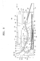
- a "C" type conventional image forming apparatus 30 includes a printing medium supplying unit 31 disposed at a low position therein.
- a feeding roller 33, an image forming unit 35, and a fixing unit 37 are vertically disposed in a row above the printing medium supplying unit 31.
- An auxiliary printing medium supplying unit (not shown) may be disposed above the printing medium supplying unit 31 to feed special kinds of printing media, such as envelopes, into the image forming apparatus 30.
- a discharging unit 38 is disposed above the fixing unit 37, and discharges printing media to a printing medium storing part 39 disposed above the image forming unit 35.
- An exposure unit 36 is disposed at a side of the image forming unit 35 to form electrostatic latent images on a photosensitive medium 35a.
- the printing medium supplying unit 31 picks up printing media loaded therein one by one and feeds the sheets of printing media to the feeding roller 33.
- the feeding roller 33 feeds each of the printing media to the image forming unit 35.
- the exposure unit 36 forms electrostatic latent images corresponding to printing data on the photosensitive medium 35a of the image forming unit 35, and the image forming unit 35 develops the electrostatic latent images into images using toner.
- the transferring roller 35b transfers the images formed on the photosensitive medium 35a of the image forming unit 35 onto a printing medium passing between the photosensitive medium 35a and the transferring roller 35b. While the printing medium with the transferred images passes through the fixing unit 37, the images are fixed onto the printing medium.
- the discharging unit 38 discharges the printing medium with the fixed images to the printing medium storing part 39, and the printing work is completed.
- the "C” type image forming apparatus 30 may be designed to have a shorter length than the length of the "S" type image forming apparatus 10. However, because the printing medium supplying unit 31, the image forming unit 35, the fixing unit 37, and the discharging unit 38 are vertically disposed in a line, the "C” type image forming apparatus 30 has a higher height. Also, it is difficult to design a "C” type image forming apparatus 30 which has a compact size because there are some dead spaces that cannot be used, such as a third space 41 between the printing medium supplying unit 31 and the exposure unit 36, and a fourth space 42 between the exposure unit 36 and the printing medium storing unit 39, as illustrated in Fig. 2 .
- each of the conventional "S" type and “C” type image forming apparatuses 10 and 30 printing media are discharged to the printing medium storing parts 19 and 39 formed at top surfaces of the image forming apparatuses 10 and 30, respectively, so that the image forming apparatuses 10 and 30 should have printing medium supporting plates 19a and 39a, respectively, to prevent the discharged printing medium from falling to the floor.
- the use of these printing medium supporting plates 19a and 39a increases the number of parts of the image forming apparatuses 10 and 30.
- EP 1,584,992 discloses an image forming apparatus having an "S" shaped printing medium path, wherein the printing medium is discharged through a top surface of a case of the apparatus.
- An aspect of the present invention provides an image forming apparatus having a more compact size than the conventional image forming apparatus.
- another aspect of the present invention provides an image forming apparatus that discharges a printing medium through a side thereof so that a space above a top surface thereof can be used.
- the present invention provides an image forming apparatus comprising a case having a top surface, a bottom surface, a front surface and a back surface, a printing medium supplying unit configured to hold a supply of printing media, an image forming unit disposed above said printing medium supplying unit and configured to form an image on a printing medium supplied from the printing medium supplying unit, a printing medium path along which the printing medium moves from the printing medium supplying unit to the image forming unit, wherein the printing medium path extends in a substantially C shape from the printing medium supplying unit then is inclined in a downwards direction towards the printing medium supplying unit to the image forming unit, a discharging unit disposed above the printing medium supplying unit to discharge the printing medium, the discharging unit being configured to discharge the printing medium through the front surface of the case, a printing medium feeding unit configured to feed the printing medium from the printing medium supplying unit to the image forming unit in a printing medium moving direction along the printing medium path, a fixing unit within the case to fix images formed by the image forming unit onto the printing
- an image forming apparatus 100 includes a case 110, a printing medium supplying unit 120, a printing medium feeding part 130, an image forming unit 140, a fixing unit 170, a discharging unit 180, and a controller 190. It is understood that other components may be used instead of or in addition to the components shown in Figure 3 and described above.
- the case 110 forms the outside of the image forming apparatus 100, and encases a printing medium supplying unit 120, an image forming unit 140, a printing medium feeding part 130, a fixing unit 170, a discharging unit 180, and a controller 190, for support and protection.
- the case 110 has a top surface 111 formed in a plane substantially parallel to a bottom surface 117. It is understood the top surface 111 is not required to be formed substantially parallel to the bottom surface 117, and may instead be curved or designed in numerous other ways.
- the top surface 111 may also be formed to have indentations for holding various items, such as, for example, sheets of paper.
- the printing medium supplying unit 120 is disposed at a lower portion of the case 110.
- the printing medium supplying unit 120 holds predetermined sheets of printing media (such as paper, transparency sheets, etc.), and picks up each sheet one by one to feed the sheet to the printing medium feeding part 130.
- the printing medium supplying unit 120 includes a printing medium cassette 123 to hold printing media and a pickup roller 121 disposed above the printing medium cassette 123 to pick the sheets up from the printing medium cassette 123.
- the image forming unit 140 is disposed above the printing medium supplying unit 120, and forms images on a printing medium.
- the image forming unit 140 includes a photosensitive medium 141 on which an exposure unit 150 irradiates laser beams to form electrostatic latent images, a developing roller 143 to develop the electrostatic latent images on the photosensitive medium 141 using toner, and a transferring roller 145 disposed to be in contact with the photosensitive medium 141.
- a printing medium fed from the printing medium supplying unit 120 passes between the photosensitive medium 141 and the transferring roller 145, images formed on the photosensitive medium 141 are transferred onto the printing medium.
- the printing medium feeding part 130 is disposed between the printing medium supplying unit 120 and the image forming unit 140, and feeds a printing medium picked up by the pickup roller 121 of the printing medium supplying unit 120 to the image forming unit 140.
- the printing medium feeding part 130 is formed substantially in the shape of the letter "C".
- a part of the printing medium feeding part 130 which extends to the image forming unit 140 is inclined in a downward direction along a printing medium moving direction.
- the shown printing medium feeding part 130 includes a printing medium reversing path 131 and a printing medium feeding path 133 that extends from a front end of the printing medium reversing path 131 and is inclined in a downward direction along the printing medium moving direction.
- the printing medium feeding part 130 need not include the printing medium reversing path 131 and/or the printing medium feeding path 133 in all aspects of the invention.
- a pair of transporting rollers 132 is preferably, but not necessarily, disposed at approximately the middle of the printing medium reversing path 131 to transport a printing medium picked up by the pickup roller 121. It is understood that one or more than two transporting rollers may be used instead of the pair of transporting rollers 132, and that these transporting rollers may be disposed in various positions other than the position shown in Figure 3 .
- a printing medium detecting sensor 138 is disposed between the pickup roller 121 and a pair of transporting rollers 132 to detect a printing medium.
- a feeding roller 135 is disposed at the location where the printing medium reversing path 131 is connected to the printing medium feeding path 133, and feeds a printing medium to the image forming unit 140.
- the printing medium feeding path 133 through which a printing medium moves from the feeding roller 135 to the photosensitive medium 141 of the image forming unit 140, is inclined in a downward direction relative to the printing medium moving direction, so that a mounting height of the image forming unit 140 is lower than the mounting height of the exposure units 16 and 36 shown in FIGs. 1 and 2 , respectively.
- the image forming unit 140 is disposed inside the case 110 in such a way that a height of a part 140a of the image forming unit 140 where images are transferred onto a printing medium is lower than a height of a top end of the feeding roller 135.
- the part 140a of the image forming unit 140 where images are transferred onto a printing medium is a contacting part disposed between the photosensitive medium 141 and the transferring roller 145. Therefore, the contacting part 140a is located at a lower position than a contacting part 135a disposed between the feeding roller 135 and a feeding backup roller 136. By lowering the mounting height of the image forming unit 140, the height H3 of the image forming apparatus 100 is lowered.
- the height H1 from the bottom surface 117 to the contacting part 135a disposed between the feeding roller 135 and the feeding backup roller 136 is set to be approximately 90 mm
- the height H2 from the bottom surface 117 to the contacting part 140a between the photosensitive medium 141 and the transferring roller 145 is preferably set to be approximately 60 mm.
- the heights H1 and H2 are not required to be adjusted to 90 mm and 60 mm, respectively, and are not required to be set to a 3:2 ratio, respectively.
- a curvature radius of the printing medium reversing path 131 is decreased too much, various problems occur. For example, a printing medium gets easily jammed, feeding a printing medium generates a loud noise, and a printing medium gets damaged during feeding. To prevent these problems from occurring, the printing medium reversing path 131 must have a curvature radius larger than a predetermined curvature radius. As a result, using the conventional method to lower a height of an image forming apparatus produces very limited results.
- a curvature radius of the printing medium reversing path 131 is substantially the same as the height of the printing medium reversing path 131 used in the conventional image forming apparatus 10 or 30.
- the printing medium feeding path 133 which is connected to the printing medium reversing path 131 through which a printing medium moves to the image forming unit 140 after being reversed, is inclined in a downward direction along a printing medium moving direction.
- the exposure unit 150 is disposed above the image forming unit 140 to irradiate laser beams corresponding to printing data so as to form electrostatic latent images on the photosensitive medium 141.
- the printing medium supplying unit 120, the image forming unit 140, and the exposure unit 150 are vertically arranged above the bottom surface 117 of the case 110.
- a height H1 from the bottom surface 117 to the contacting part 135a of the feeding roller 135 is approximately 90 mm
- a height H3 from the bottom surface 117 to the top surface 111 of the case 110 is approximately 150 mm or less.
- H1 and H3 are not limited to being 90 mm and 150 mm, respectively, and are not required to be set to a 3:5 ratio, respectively.
- the fixing unit 170 is disposed at a side of the image forming unit 140 above the printing medium supplying unit 120.
- the fixing unit 170 fixes images, which are transferred onto a printing medium when the printing medium passes through the image forming unit 140, using high temperature and high pressure.
- the fixing unit 170 includes a pressure roller 172 to press a printing medium and a heating roller 171 to generate a high temperature.
- the fixing unit 170 is preferably disposed in the case 110 in such a way that a height of a contacting part 170a disposed between the pressure roller 172 and the heating roller 171 where a printing medium passes through the fixing unit 170 is substantially the same as the height of the contacting part 140a disposed between the photosensitive medium 141 and the transferring roller 145 of the image forming unit 140.
- a fixing feeding path 160 through which a printing medium moves from the image forming unit 140 to the fixing unit 170 is shown formed in a concave shape, as illustrated in Fig. 3 . Therefore, a printing medium moves in a downward direction from the feeding roller 135 to the image forming unit 140, and then moves in an upward direction while passing along the fixing feeding path 160.
- the contacting parts 170a and 140a are not required to be disposed at substantially the same height. It is further understood that the fixing feeding path 160 is not necessarily required to be concave, and may instead take other shapes, such as, for example, a flat horizontal shape.
- the discharging unit 180 is disposed at a side of the fixing unit 170 above the printing medium supplying unit 120, and discharges a printing medium with fixed images passing through the fixing unit 170 to the outside of the image forming apparatus 100 through a side 113 of the case 110.
- a side 113 namely, a right side in Fig. 3
- a front surface of the case 110 a side 113 (namely, a right side in Fig. 3 ) of the case 110 through which a printing medium is discharged
- an opposite side 115 namely, a left side in Fig. 3 ) of the case 110 is referred as a back surface of the case 110.
- the shown discharging unit 180 is configured to include a plurality of discharging rollers 181.
- the discharging unit 180 is shown disposed in such a way that a part 180a of the discharging unit 180 through which a printing medium passes is located at substantially the same height as the part 170a of the fixing unit 170 through which a printing medium passes through.
- the discharging unit 180 is disposed in such a way that a height of the part 180a of the discharging unit 180 through which a printing medium passes is higher than the height of the part 170a of the fixing unit 170.
- the reason why it is preferable to mount the part 180a at a higher height than the part 170a is because mounting the discharging unit 180 at a higher level allows a large amount of discharged printing media to be piled up.
- the part 180a may also be mounted at a lower height than the part 170a, in which case a lower level of discharged printing media can be piled up.
- the discharging unit 180 is shown disposed near the front surface 113 of the case 110 so that printing media are directly discharged to the outside of the case 110.
- the discharging unit 180 is disposed at a predetermined distance from the front surface 113 inside of the case 110, and a printing medium supporting part 183 is disposed between the discharging unit 180 and the front surface 113 of the case 110 to receive printing media 187 discharged by the discharging unit 180.
- a discharging space 185 where a predetermined sheet of printing media discharged from the discharging unit 180 can be piled up is formed above the printing medium supporting part 183.
- the discharging space 185 is preferably formed as a recess, such as a concave shape, in the front surface 113 of the case 110.
- the discharging space 185 allows some of the space above the printing medium supplying unit 120 to be used for receiving discharged printing media, thus providing a compact image forming apparatus 100.
- the printing medium supporting part 183 is shown formed integrally with the case 110, as illustrated in Fig. 3 .
- the printing medium supporting part 183 may be formed as a separate part which attaches and detaches to and from the front side 113 of the case 110.
- the printing medium supporting part 183 may be used when a resting surface 101, such as a top surface of a desk where the image forming apparatus 100 is set up, does not have enough space to receive printing media 187 discharged from the image forming apparatus 100.
- the printing medium supporting part 183 may be disposed to be inclined in an upward or downward direction with respect to the printing medium discharging direction, or may be disposed parallel to the resting surface 101. As illustrated in Fig. 3 , when the printing medium supporting part 183 is inclined in a downward direction with respect to the printing medium discharging direction, a printing medium discharged by the discharging unit 180 moves in a stable fashion along the printing medium supporting part 183, and is thus piled up in a stable fashion on the resting surface 101, such as a desk, where the image forming apparatus 100 is set up. In other words, a space on the resting surface 101, such as a top surface of a desk, where the image forming apparatus 100 is set up can be used as a space for piling up discharged printing media.
- the controller 190 controls the printing medium supplying unit 120, the image forming unit 140, the feeding roller 135, the fixing unit 170, and the discharging unit 180 to control printing operations.
- the controller 190 is shown disposed above the discharging unit 180 and the printing medium supporting part 183.
- the controller 190 includes a circuit board 191 for controlling printing operations, an operation display part 193 (see Fig. 4 ) for displaying a printing status, a power switch 192 for turning on and off power supplied to the image forming apparatus 100, and control buttons 195 (see Fig. 4 ) for users to control the image forming apparatus 100.
- the controller 190 can be otherwise located.
- the circuit board 191 is disposed above the discharging unit 180 and the discharging space 185 to maximize the use of an inner space of the case 110. Since the circuit board 191 is disposed near the front surface 113 of the case 110 according to the arrangement of an embodiment, the circuit board 191 is located close to the operation display part 193, the power switch 192, and the control buttons 195, which are each shown disposed on the front surface 113 of the case 110. Therefore, it is not required to fix each of the operation display part 193, the power switch 192, and the control buttons 195 to the case 110, and then to connect each of these components to the circuit board 191 using electrical wires. In other words, the operation display part 193, the power switch 192, and the control buttons 195 may all be directly disposed on the circuit board 191.
- the image forming apparatus 100 does not require separate parts to fix each of the operation display part 193, the power switch 192, and the control buttons 195 to the case 110, decreasing the cost of materials and assembly. It is understood, however, that the operation display part 193, the power switch 192, and the control buttons 195 are not required to be fixed to the circuit board 191, and that these components may each be installed separately to the case 110, or some components may be fixed to the circuit board 191 and other components may be separately installed to the case 110.
- the operation display part 193, the power switch 192, and the control buttons 195 are preferably arranged at the front surface 113 of the case 110, as illustrated in Fig. 4 .
- the operation display part 193, the power switch 192, and the control buttons 195 may be arranged at a front area of the top surface 111 of the case 110, as illustrated in Fig. 5 .
- the controller 190 may be connected to an electronic device, such as a computer or a digital camera, via a network or wirelessly.
- An image forming apparatus 100 may further include an auxiliary printing medium supplying unit 200 for supplying special kinds of printing media, such as an envelope, a thick printing medium, etc., into the image forming apparatus 100. It is understood that regular printing media may also be supplied into the image forming apparatus 100 by the auxiliary printing medium supplying unit 200.
- the auxiliary printing medium supplying unit 200 is preferably disposed between the top surface 111 of the case 110 and a top end of the printing medium feeding part 130, although may be disposed in other locations as well, such as off to a side of the case 110.
- the feeding roller 135 is disposed at the top end of the printing medium feeding part 130 so that the auxiliary printing medium supplying unit 200 is disposed between the top surface 111 of the case 110 and the feeding roller 135.
- a printing medium entrance 201 of the auxiliary printing medium supplying unit 200 is formed at a back area of the top surface 111 of the case 110. Since the printing medium entrance 201 according to an embodiment is formed at the top surface 111 of the case 110, users can supply printing media, including special kinds of printing media, in a downward direction. Therefore, it is easy to supply printing media into the image forming apparatus 100 using the auxiliary printing medium supplying unit 200.
- the auxiliary printing medium supplying unit 200 may further include an auxiliary printing medium detecting sensor 203.
- the controller 190 rotates the feeding roller 135 to feed the printing medium entering the auxiliary printing medium supplying unit 200 to the image forming unit 140.
- the auxiliary printing medium supplying unit 200 may include a door 202 to selectively open or close the printing medium entrance 201.
- users open the door 202 to supply a printing medium through the printing medium entrance 201.
- users can close the door 202 to prevent foreign materials, such as dust, from entering the case 110 through the printing medium entrance 201.
- the door 202 may be fixed by a hinge so that users can easily open or close the door 202 by hand, although the door 202 may also be controlled automatically, for example, by the controller 190. It is understood that the door 202 may be fixed to the case 110 with various types of fasteners other than a hinge.
- an operation of an image forming apparatus 100 Upon receiving a printing order from a host (not shown), such as a computer connected to the image forming apparatus 100, the controller 190 operates the pickup roller 121 to pick up a printing medium loaded into the printing medium supplying unit 120 and to feed the printing medium to the feeding roller 135.
- the controller 190 operates the transporting roller 132 and the feeding roller 135 to feed the printing medium to the image forming unit 140.
- the controller 190 controls the exposure unit 150 to irradiate laser beams corresponding to printing data onto the photosensitive medium 141 of the image forming unit 140.
- the electrostatic latent images corresponding to printing data received from the host are formed on the photosensitive medium 141.
- toner supplied by the developing roller 143 develops the electrostatic latent images into toner images.
- the toner images on the photosensitive medium 141 are transferred onto a printing medium which is fed by the feeding roller 135 to pass between the photosensitive medium 141 and the transferring roller 145.
- the printing medium having the transferred images continues to move to the fixing unit 170.
- the printing medium moves to the fixing unit 170, it passes between the pressure roller 172 and the heating roller 171.
- the transferred images are fixed on the printing medium by the high pressure generated by the pressure roller 172 and the high temperature generated by the heating roller 171.
- the printing medium having the fixed images is discharged through the front surface 113 of the image forming apparatus 100 by the discharging unit 180.
- the discharged printing medium moves in a stable fashion along the printing medium supporting part 183 disposed in front of the discharging unit 180.
- the printing medium 187 piles up on the printing medium supporting part 183 of the image forming apparatus 100 and the resting surface101, as illustrated in Fig. 3 .
- the image forming unit 140 and the fixing unit 170 are located lower than the feeding roller 135. Arranging the printing medium feeding part 130, the image forming unit 140, and the fixing unit 170 according to aspects described above minimizes unused spaces inside the image forming apparatus 100, such as, for example, the first, second, third, and fourth spaces 21, 22, 41 and 42 inside the conventional image forming apparatus 10 and 30 as illustrated in Figs. 1 and 2 .
- the image forming apparatus 100 By minimizing these unused spaces 21, 22, 41, and 42, the image forming apparatus 100 according to an embodiment has a height much lower than the height of the conventional image forming apparatus 10 and 30. Therefore, an image forming apparatus 100 according to aspects of the present invention has a more compact and slim size than the sizes of the conventional image forming apparatuses 10 and 30.
- the image forming apparatus 100 since the image forming apparatus 100 according to aspects of the present invention discharges a printing medium through the front surface 113 of the case 110, the top surface 111 of the case 110 may be formed in a plane substantially parallel to the bottom surface 117 thereof. Therefore, users can use a space above the top surface 111 of the case 110 for their own convenience. For example, users may put any a small vase, a picture frame, a coffee cup, etc. on the top surface 111 of the image forming apparatus 100. Alternatively, users can put a digital apparatus, such as a laptop computer or a DVD player, on the top surface 111 of the image forming apparatus 100. Users cannot, however, put anything on top surfaces of the cases of the conventional image forming apparatuses 10 and 30.
- the image forming apparatus 100 because the image forming unit 140 is disposed in such a way that a height of a part 140a of the image forming unit through which a printing medium passes through is lower than a height of a contacting part 135a of a feeding roller 135, the image forming apparatus 100 may be designed to have a lower height than a height of the conventional image forming apparatuses 10 and 30. Therefore, an image forming apparatus 100 according to aspects of the present invention may have a more compact and slim size than the sizes of the conventional image forming apparatuses 10 and 30.
- an image forming apparatus 100 since a printing medium is discharged through a side 113 of a case 110, space above a printing medium supplying unit 120, along with space on a resting area 101, such as a top surface of a desk where the image forming apparatus 100 is set up, can be used as a storing space for receiving discharged printing media. As a result, a separate printing medium supporting plate is not required.
- a top surface 111 of a case 110 is a closed surface and formed in a plane, users can freely use a space above the top surface of the case.
- an image forming apparatus 100 is configured to supply special kinds of printing media, such as envelopes, through a back area of a top surface 111 of a case 110 in a downward direction at, users can easily supply special kinds of printing media into the image forming apparatus 100.
- an operation display part 193, a power switch 192, and control buttons 195 which enable users to control the image forming apparatus 100, may be directly mounted on the circuit board 191.
- additional parts are not required to separately mount the operation display part 193, the power switch 192, and the control buttons 195 on the case 110 and to connect these components to the circuit board 191. Therefore, manufacturing and assembly costs of the image forming apparatus 100 are decreased.
- the apparatus can further include facsimile, copying, and/or scanning functionality. Additionally, while described in the context of electro photographic image forming apparatuses, it is understood that the invention can be used in other devices.
Landscapes
- Physics & Mathematics (AREA)
- General Physics & Mathematics (AREA)
- Electrophotography Configuration And Component (AREA)
- Accessory Devices And Overall Control Thereof (AREA)
Applications Claiming Priority (1)
| Application Number | Priority Date | Filing Date | Title |
|---|---|---|---|
| KR1020060088284A KR101297178B1 (ko) | 2006-09-12 | 2006-09-12 | 화상형성장치 |
Publications (2)
| Publication Number | Publication Date |
|---|---|
| EP1900534A1 EP1900534A1 (en) | 2008-03-19 |
| EP1900534B1 true EP1900534B1 (en) | 2011-06-15 |
Family
ID=38543878
Family Applications (1)
| Application Number | Title | Priority Date | Filing Date |
|---|---|---|---|
| EP07110858A Expired - Fee Related EP1900534B1 (en) | 2006-09-12 | 2007-06-22 | Image forming apparatus |
Country Status (4)
| Country | Link |
|---|---|
| US (2) | US20080063450A1 (ko) |
| EP (1) | EP1900534B1 (ko) |
| KR (1) | KR101297178B1 (ko) |
| CN (1) | CN101144998B (ko) |
Cited By (1)
| Publication number | Priority date | Publication date | Assignee | Title |
|---|---|---|---|---|
| WO2023038626A1 (en) * | 2021-09-09 | 2023-03-16 | Hewlett-Packard Development Company, L.P. | Printers including auxiliary print media trays |
Families Citing this family (6)
| Publication number | Priority date | Publication date | Assignee | Title |
|---|---|---|---|---|
| KR101443282B1 (ko) * | 2007-04-16 | 2014-09-26 | 삼성전자주식회사 | 화상형성장치 |
| US8200117B2 (en) * | 2007-04-16 | 2012-06-12 | Samsung Electronics Co., Ltd. | Image forming apparatus having pivotable upper body |
| JP2009057130A (ja) * | 2007-08-30 | 2009-03-19 | Ricoh Co Ltd | 画像形成装置 |
| JP7243048B2 (ja) * | 2018-06-13 | 2023-03-22 | セイコーエプソン株式会社 | 印刷装置 |
| JP7125007B2 (ja) * | 2018-09-19 | 2022-08-24 | セイコーエプソン株式会社 | 記録装置 |
| JP7434924B2 (ja) | 2020-01-23 | 2024-02-21 | セイコーエプソン株式会社 | 記録装置 |
Family Cites Families (26)
| Publication number | Priority date | Publication date | Assignee | Title |
|---|---|---|---|---|
| JPS52110640A (en) * | 1976-03-15 | 1977-09-16 | Minolta Camera Co Ltd | Static latent image transferring electrophotographic copier |
| US4583844A (en) * | 1983-09-19 | 1986-04-22 | Konishiroku Photo Industry Co., Ltd. | Image recording apparatus with separable upper and lower sections and displaceable paper feed unit |
| FR2588139B1 (fr) * | 1985-09-30 | 1994-03-04 | Canon Kk | Appareil de formation d'images. |
| JPH0255243U (ko) * | 1988-10-17 | 1990-04-20 | ||
| JP2851303B2 (ja) * | 1989-05-18 | 1999-01-27 | 株式会社リコー | プリンター装置 |
| DE69219915T2 (de) * | 1991-01-25 | 1997-11-20 | Canon Kk | Elektrophotographisches Bilderzeugungsgerät mit einer Montieranordnung für die Arbeitseinheit |
| US5347349A (en) * | 1992-07-21 | 1994-09-13 | Konica Corporation | Image forming apparatus having a protective gate member |
| US5526104A (en) * | 1994-03-29 | 1996-06-11 | Matsushita Electric Industrial Co., Ltd. | Image forming apparatus with improved manual paper feed inlet |
| JPH0895468A (ja) * | 1994-09-26 | 1996-04-12 | Canon Inc | プロセスカートリッジ及び画像形成装置 |
| JP3581479B2 (ja) * | 1996-03-11 | 2004-10-27 | キヤノン株式会社 | 画像形成装置 |
| JPH1010892A (ja) * | 1996-06-27 | 1998-01-16 | Canon Inc | 画像形成装置 |
| US5913095A (en) * | 1997-08-25 | 1999-06-15 | Ricoh Company, Ltd. | Image forming apparatus |
| JPH11147650A (ja) * | 1997-09-04 | 1999-06-02 | Ricoh Co Ltd | 記録紙スタッカ装置 |
| JP2000335788A (ja) * | 1999-05-27 | 2000-12-05 | Canon Inc | シート材給送装置及び画像形成装置 |
| ATE251041T1 (de) * | 2000-02-24 | 2003-10-15 | Seiko Epson Corp | Papierförderer, hilfsrolle, papierzuführverfahren unter verwendung derselben, und aufzeichnungsgerät derselben enthaltend |
| JP2004069884A (ja) * | 2002-08-05 | 2004-03-04 | Brother Ind Ltd | 画像読み取り手段を有する画像形成装置 |
| KR100449733B1 (ko) * | 2002-08-10 | 2004-09-22 | 삼성전자주식회사 | 페이스-업 및 페이스-다운 배출이 가능한 프린터 |
| US8582125B2 (en) * | 2003-07-22 | 2013-11-12 | Hewlett-Packard Development Company, L.P. | Variable support structure and media sheet separator |
| JP4321235B2 (ja) * | 2003-11-21 | 2009-08-26 | 富士ゼロックス株式会社 | 画像処理装置及び画像処理プログラム |
| JP4431961B2 (ja) * | 2004-03-05 | 2010-03-17 | ブラザー工業株式会社 | 画像記録装置 |
| JP2005292356A (ja) * | 2004-03-31 | 2005-10-20 | Brother Ind Ltd | 画像形成装置 |
| KR100612008B1 (ko) * | 2004-04-10 | 2006-08-11 | 삼성전자주식회사 | 화상형성장치 |
| JP2006003649A (ja) * | 2004-06-17 | 2006-01-05 | Brother Ind Ltd | 画像形成装置 |
| JP4437536B2 (ja) * | 2004-06-17 | 2010-03-24 | ブラザー工業株式会社 | 画像形成装置 |
| US7631965B2 (en) * | 2005-02-28 | 2009-12-15 | Brother Kogyo Kabushiki Kaisha | Image-recording device having movable carriage to which flexible flat cable and flexible ink supply tubes are connected |
| JP2006248062A (ja) * | 2005-03-11 | 2006-09-21 | Seiko Epson Corp | スキャナプリンタ複合機 |
-
2006
- 2006-09-12 KR KR1020060088284A patent/KR101297178B1/ko active IP Right Grant
-
2007
- 2007-02-27 US US11/679,473 patent/US20080063450A1/en not_active Abandoned
- 2007-04-29 CN CN2007101077759A patent/CN101144998B/zh not_active Expired - Fee Related
- 2007-06-22 EP EP07110858A patent/EP1900534B1/en not_active Expired - Fee Related
-
2014
- 2014-12-09 US US14/564,409 patent/US9618894B2/en active Active
Cited By (1)
| Publication number | Priority date | Publication date | Assignee | Title |
|---|---|---|---|---|
| WO2023038626A1 (en) * | 2021-09-09 | 2023-03-16 | Hewlett-Packard Development Company, L.P. | Printers including auxiliary print media trays |
Also Published As
| Publication number | Publication date |
|---|---|
| CN101144998A (zh) | 2008-03-19 |
| EP1900534A1 (en) | 2008-03-19 |
| US9618894B2 (en) | 2017-04-11 |
| CN101144998B (zh) | 2013-11-27 |
| KR20080024020A (ko) | 2008-03-17 |
| KR101297178B1 (ko) | 2013-08-21 |
| US20150093160A1 (en) | 2015-04-02 |
| US20080063450A1 (en) | 2008-03-13 |
Similar Documents
| Publication | Publication Date | Title |
|---|---|---|
| US9618894B2 (en) | Image forming apparatus having a compact size | |
| US8072655B2 (en) | Image reader for use in an image forming apparatus, and contamination check method of guide film for the same | |
| JP6732548B2 (ja) | シート排出装置及び画像形成装置 | |
| JP4297912B2 (ja) | 給紙装置 | |
| JP4764803B2 (ja) | 給紙装置におけるシート材の積載量演算方法、補給量演算方法、及び給紙装置 | |
| JP3602460B2 (ja) | 給紙装置 | |
| CN101519167A (zh) | 图像形成装置 | |
| JP2006264980A (ja) | 大容量給紙装置および画像形成装置 | |
| JP4739139B2 (ja) | 給紙装置、及び画像形成装置 | |
| JP4299840B2 (ja) | 給紙装置及び画像形成装置 | |
| JP4062114B2 (ja) | 給紙装置及び画像形成装置 | |
| JP2002003013A (ja) | 給紙装置 | |
| JP4231764B2 (ja) | シート給送装置 | |
| JP2007238312A (ja) | 給紙装置及び画像形成装置 | |
| JP2009051589A (ja) | 給紙装置、画像形成装置 | |
| JP3933874B2 (ja) | 記録材送り出し装置及び画像形成装置 | |
| JP3932194B2 (ja) | シート給送装置 | |
| JPH0558505A (ja) | 給紙装置 | |
| KR20050074218A (ko) | 화상형성장치의 자동양면급지유닛 | |
| JP2005178999A (ja) | 給紙装置および画像形成装置 | |
| KR20090002999A (ko) | 인쇄매체공급유닛 및 이를 포함하는 화상형성장치 | |
| JP2007238313A (ja) | 給紙装置及び画像形成装置 | |
| JP2009196791A (ja) | 給紙装置及び該給紙装置を備えた画像形成装置 | |
| JPH04125226A (ja) | 縦型ページプリンタ用給紙装置 | |
| JP2016050049A (ja) | 給紙装置および画像形成装置 |
Legal Events
| Date | Code | Title | Description |
|---|---|---|---|
| PUAI | Public reference made under article 153(3) epc to a published international application that has entered the european phase |
Free format text: ORIGINAL CODE: 0009012 |
|
| AK | Designated contracting states |
Kind code of ref document: A1 Designated state(s): AT BE BG CH CY CZ DE DK EE ES FI FR GB GR HU IE IS IT LI LT LU LV MC MT NL PL PT RO SE SI SK TR |
|
| AX | Request for extension of the european patent |
Extension state: AL BA HR MK YU |
|
| AKX | Designation fees paid | ||
| 17P | Request for examination filed |
Effective date: 20080918 |
|
| RBV | Designated contracting states (corrected) |
Designated state(s): DE FR GB NL |
|
| REG | Reference to a national code |
Ref country code: DE Ref legal event code: 8566 |
|
| 17Q | First examination report despatched |
Effective date: 20090708 |
|
| GRAP | Despatch of communication of intention to grant a patent |
Free format text: ORIGINAL CODE: EPIDOSNIGR1 |
|
| GRAS | Grant fee paid |
Free format text: ORIGINAL CODE: EPIDOSNIGR3 |
|
| GRAA | (expected) grant |
Free format text: ORIGINAL CODE: 0009210 |
|
| AK | Designated contracting states |
Kind code of ref document: B1 Designated state(s): DE FR GB NL |
|
| REG | Reference to a national code |
Ref country code: GB Ref legal event code: FG4D |
|
| REG | Reference to a national code |
Ref country code: DE Ref legal event code: R096 Ref document number: 602007015180 Country of ref document: DE Effective date: 20110721 |
|
| REG | Reference to a national code |
Ref country code: NL Ref legal event code: T3 |
|
| PLBE | No opposition filed within time limit |
Free format text: ORIGINAL CODE: 0009261 |
|
| STAA | Information on the status of an ep patent application or granted ep patent |
Free format text: STATUS: NO OPPOSITION FILED WITHIN TIME LIMIT |
|
| PG25 | Lapsed in a contracting state [announced via postgrant information from national office to epo] |
Ref country code: FR Free format text: LAPSE BECAUSE OF NON-PAYMENT OF DUE FEES Effective date: 20110816 |
|
| REG | Reference to a national code |
Ref country code: FR Ref legal event code: ST Effective date: 20120330 |
|
| 26N | No opposition filed |
Effective date: 20120316 |
|
| REG | Reference to a national code |
Ref country code: DE Ref legal event code: R097 Ref document number: 602007015180 Country of ref document: DE Effective date: 20120316 |
|
| REG | Reference to a national code |
Ref country code: NL Ref legal event code: PD Owner name: S-PRINTING SOLUTION CO., LTD.; KO Free format text: DETAILS ASSIGNMENT: CHANGE OF OWNER(S), ASSIGNMENT; FORMER OWNER NAME: SAMSUNG ELECTRONICS CO., LTD. Effective date: 20170221 |
|
| REG | Reference to a national code |
Ref country code: GB Ref legal event code: 732E Free format text: REGISTERED BETWEEN 20170406 AND 20170412 |
|
| REG | Reference to a national code |
Ref country code: DE Ref legal event code: R082 Ref document number: 602007015180 Country of ref document: DE Representative=s name: MITSCHERLICH, PATENT- UND RECHTSANWAELTE PARTM, DE Ref country code: DE Ref legal event code: R082 Ref document number: 602007015180 Country of ref document: DE Ref country code: DE Ref legal event code: R081 Ref document number: 602007015180 Country of ref document: DE Owner name: HP PRINTING KOREA CO., LTD., SUWON-SI, KR Free format text: FORMER OWNER: SAMSUNG ELECTRONICS CO., LTD., SUWON-SI, GYEONGGI-DO, KR Ref country code: DE Ref legal event code: R081 Ref document number: 602007015180 Country of ref document: DE Owner name: HEWLETT-PACKARD DEVELOPMENT COMPANY, L.P., SPR, US Free format text: FORMER OWNER: SAMSUNG ELECTRONICS CO., LTD., SUWON-SI, GYEONGGI-DO, KR Ref country code: DE Ref legal event code: R081 Ref document number: 602007015180 Country of ref document: DE Owner name: S-PRINTING SOLUTION CO., LTD., SUWON-SI, KR Free format text: FORMER OWNER: SAMSUNG ELECTRONICS CO., LTD., SUWON-SI, GYEONGGI-DO, KR |
|
| REG | Reference to a national code |
Ref country code: NL Ref legal event code: HC Owner name: HP PRINTING KOREA CO., LTD.; KR Free format text: DETAILS ASSIGNMENT: CHANGE OF OWNER(S), CHANGE OF OWNER(S) NAME; FORMER OWNER NAME: S-PRINTING SOLUTION CO., LTD. Effective date: 20180816 |
|
| REG | Reference to a national code |
Ref country code: DE Ref legal event code: R082 Ref document number: 602007015180 Country of ref document: DE Ref country code: DE Ref legal event code: R081 Ref document number: 602007015180 Country of ref document: DE Owner name: HP PRINTING KOREA CO., LTD., SUWON-SI, KR Free format text: FORMER OWNER: S-PRINTING SOLUTION CO., LTD., SUWON-SI, GYEONGGI-DO, KR Ref country code: DE Ref legal event code: R081 Ref document number: 602007015180 Country of ref document: DE Owner name: HEWLETT-PACKARD DEVELOPMENT COMPANY, L.P., SPR, US Free format text: FORMER OWNER: S-PRINTING SOLUTION CO., LTD., SUWON-SI, GYEONGGI-DO, KR Ref country code: DE Ref legal event code: R082 Ref document number: 602007015180 Country of ref document: DE Representative=s name: SCHOPPE, ZIMMERMANN, STOECKELER, ZINKLER, SCHE, DE |
|
| REG | Reference to a national code |
Ref country code: NL Ref legal event code: PD Owner name: HEWLETT-PACKARD DEVELOPMENT COMPANY, L.P.; US Free format text: DETAILS ASSIGNMENT: CHANGE OF OWNER(S), CHANGE OF LEGAL ENTITY; FORMER OWNER NAME: SAMSUNG ELECTRONICS CO., LTD. Effective date: 20191030 |
|
| REG | Reference to a national code |
Ref country code: DE Ref legal event code: R081 Ref document number: 602007015180 Country of ref document: DE Owner name: HEWLETT-PACKARD DEVELOPMENT COMPANY, L.P., SPR, US Free format text: FORMER OWNER: HP PRINTING KOREA CO., LTD., SUWON-SI, GYEONGGI-DO, KR |
|
| REG | Reference to a national code |
Ref country code: GB Ref legal event code: 732E Free format text: REGISTERED BETWEEN 20191212 AND 20191218 |
|
| REG | Reference to a national code |
Ref country code: DE Ref legal event code: R082 Ref document number: 602007015180 Country of ref document: DE Representative=s name: SCHOPPE, ZIMMERMANN, STOECKELER, ZINKLER, SCHE, DE |
|
| PGFP | Annual fee paid to national office [announced via postgrant information from national office to epo] |
Ref country code: NL Payment date: 20220523 Year of fee payment: 16 |
|
| PGFP | Annual fee paid to national office [announced via postgrant information from national office to epo] |
Ref country code: GB Payment date: 20220520 Year of fee payment: 16 Ref country code: DE Payment date: 20220518 Year of fee payment: 16 |
|
| REG | Reference to a national code |
Ref country code: DE Ref legal event code: R119 Ref document number: 602007015180 Country of ref document: DE |
|
| REG | Reference to a national code |
Ref country code: NL Ref legal event code: MM Effective date: 20230701 |
|
| GBPC | Gb: european patent ceased through non-payment of renewal fee |
Effective date: 20230622 |
|
| PG25 | Lapsed in a contracting state [announced via postgrant information from national office to epo] |
Ref country code: NL Free format text: LAPSE BECAUSE OF NON-PAYMENT OF DUE FEES Effective date: 20230701 |
|
| PG25 | Lapsed in a contracting state [announced via postgrant information from national office to epo] |
Ref country code: DE Free format text: LAPSE BECAUSE OF NON-PAYMENT OF DUE FEES Effective date: 20240103 Ref country code: GB Free format text: LAPSE BECAUSE OF NON-PAYMENT OF DUE FEES Effective date: 20230622 |