EP1899548B1 - Teilbarer kletterschuh einer kletterschalung - Google Patents
Teilbarer kletterschuh einer kletterschalung Download PDFInfo
- Publication number
- EP1899548B1 EP1899548B1 EP06761666.4A EP06761666A EP1899548B1 EP 1899548 B1 EP1899548 B1 EP 1899548B1 EP 06761666 A EP06761666 A EP 06761666A EP 1899548 B1 EP1899548 B1 EP 1899548B1
- Authority
- EP
- European Patent Office
- Prior art keywords
- climbing
- shoe
- wall
- claws
- shoe part
- Prior art date
- Legal status (The legal status is an assumption and is not a legal conclusion. Google has not performed a legal analysis and makes no representation as to the accuracy of the status listed.)
- Active
Links
Images





Classifications
-
- E—FIXED CONSTRUCTIONS
- E04—BUILDING
- E04G—SCAFFOLDING; FORMS; SHUTTERING; BUILDING IMPLEMENTS OR AIDS, OR THEIR USE; HANDLING BUILDING MATERIALS ON THE SITE; REPAIRING, BREAKING-UP OR OTHER WORK ON EXISTING BUILDINGS
- E04G11/00—Forms, shutterings, or falsework for making walls, floors, ceilings, or roofs
- E04G11/06—Forms, shutterings, or falsework for making walls, floors, ceilings, or roofs for walls, e.g. curved end panels for wall shutterings; filler elements for wall shutterings; shutterings for vertical ducts
- E04G11/20—Movable forms; Movable forms for moulding cylindrical, conical or hyperbolical structures; Templates serving as forms for positioning blocks or the like
-
- E—FIXED CONSTRUCTIONS
- E04—BUILDING
- E04G—SCAFFOLDING; FORMS; SHUTTERING; BUILDING IMPLEMENTS OR AIDS, OR THEIR USE; HANDLING BUILDING MATERIALS ON THE SITE; REPAIRING, BREAKING-UP OR OTHER WORK ON EXISTING BUILDINGS
- E04G11/00—Forms, shutterings, or falsework for making walls, floors, ceilings, or roofs
- E04G11/06—Forms, shutterings, or falsework for making walls, floors, ceilings, or roofs for walls, e.g. curved end panels for wall shutterings; filler elements for wall shutterings; shutterings for vertical ducts
- E04G11/20—Movable forms; Movable forms for moulding cylindrical, conical or hyperbolical structures; Templates serving as forms for positioning blocks or the like
- E04G11/28—Climbing forms, i.e. forms which are not in contact with the poured concrete during lifting from layer to layer and which are anchored in the hardened concrete
-
- B—PERFORMING OPERATIONS; TRANSPORTING
- B66—HOISTING; LIFTING; HAULING
- B66F—HOISTING, LIFTING, HAULING OR PUSHING, NOT OTHERWISE PROVIDED FOR, e.g. DEVICES WHICH APPLY A LIFTING OR PUSHING FORCE DIRECTLY TO THE SURFACE OF A LOAD
- B66F11/00—Lifting devices specially adapted for particular uses not otherwise provided for
- B66F11/04—Lifting devices specially adapted for particular uses not otherwise provided for for movable platforms or cabins, e.g. on vehicles, permitting workmen to place themselves in any desired position for carrying out required operations
-
- E—FIXED CONSTRUCTIONS
- E04—BUILDING
- E04G—SCAFFOLDING; FORMS; SHUTTERING; BUILDING IMPLEMENTS OR AIDS, OR THEIR USE; HANDLING BUILDING MATERIALS ON THE SITE; REPAIRING, BREAKING-UP OR OTHER WORK ON EXISTING BUILDINGS
- E04G3/00—Scaffolds essentially supported by building constructions, e.g. adjustable in height
- E04G3/20—Scaffolds essentially supported by building constructions, e.g. adjustable in height supported by walls
Definitions
- the invention relates to a climbing shoe for a climbing formwork, which has a wall shoe part for fastening the climbing shoe to a wall of a concreting section of a structure, wherein the climbing shoe further comprises a sliding shoe part, are provided on the claws, which are formed such that a climbing rail between the Claws along the wall is slidably arranged and can be kept guided by the claws by the claws are formed such that the claws can embrace portions of a climbing rail.
- Climbing shoes which embrace a climbing rail are known in such a way that, on the one hand, they can be displaced in the climbing shoes and, on the other hand, they hold the climbing rails on the wall of a building. If the climbing shoes are to be removed from a wall, then the Climbing rails are moved out of the climbing shoes and then it is possible to reduce the attached to provided anchor points of a concreting climbing shoes.
- the US 2003/052249 A1 describes a climbing form with climbing shoes.
- a scaffolding unit is guided on climbing rails along a wall of a concreting section.
- the climbing rails are in turn guided slidably in climbing shoes along the wall.
- a climbing shoe z. B. by the Kr 1020020062259 A known.
- the climbing shoe described therein represents a so-called wall shoe, whose base body can be fastened by means of screws to a wall of a concreting section.
- Two guide elements are pivotally mounted on the main body of the shoe wall and can embrace a rail-shaped component to keep it slidable along the wall.
- KR 20020047071 A also forms the closest prior art to claim 1.
- the object of the invention is to provide climbing shoes that can be removed from a fixed attachment to a concreting a wall even when they are penetrated by a climbing rail.
- the climbing shoe has a sliding shoe part with a pivotable and / or telescopic claw and the sliding shoe part is connected to the wall shoe part which can be fastened to a vertically oriented wall of the climbing shoe a horizontal and parallel to the vertical wall aligned stub shaft releasably connected.
- the removal of a climbing shoe is possible in a simple manner, because it can also be shared in addition to the swivel and / or telescopic claw.
- the climbing shoe according to the invention can always already from a wall under several attached to a building climbing shoes be removed if it is no longer needed in use for the proposed climbing formwork. This is always the case when a concreting section is completed and a new concreting section is to be created.
- the climbing rails used for climbing formwork have a length which is greater than the height of two concreting sections to be created.
- the bottom climbing shoes must always remain so long on a wall to be created until the climbing rails are climbed up so far that they completely release the bottom climbing shoes. If the climbing rails are out of engagement with the climbing shoes, then these climbing shoes can be dismantled. To dismantle this known from the prior art climbing shoes auxiliary stages or casters are usually necessary and for the functional fair operation of a known from the prior art climbing formwork a larger storage of climbing shoes is necessary so that the known climbing formworks can be operated.
- climbing shoes according to the invention are used, then additional follow-up platforms are unnecessary for dismantling climbing shoes which are no longer required, because these climbing shoes can already be removed from a wall while they are still in engagement with the climbing rails. If necessary, the climbing shoe according to the invention can also be grown at any point on a climbing rail. All the advantages that result from dismantling a climbing shoe from a climbing rail can also be transferred to the installation of a climbing shoe on a climbing rail.
- a particular embodiment of a climbing shoe allows the removal of the climbing shoe when two claws of a climbing shoe engage around the climbing rail in sections and a claw is pivotally provided on the sliding shoe.
- a pivotable bearing is simple and inexpensive to form a claw of the shoe and the pivoting movement can be locked easily via a Absteckbolzen. If the locking pin is removed, the claw can be swung open be removed from the climbing rail. If the claw is swiveled open, then it can also be blocked via the same locking pin, so that it is ensured that when the pivotable claw is removed, it does not pivot uncontrollably.
- the climbing shoe in the wall shoe part on a vertically oriented axis has the advantage that the climbing shoe can also be aligned on rounded walls of concreting sections in such a way that adjacent climbing shoes always align the climbing rails held in the climbing shoes and the consoles connected thereto in parallel to one another.
- FIGS. In one embodiment, the climbing shoe according to the invention is shown and described.
- Fig. 1 shows in a side view and partially cut a climbing shoe 10, as it is attached to a wall 12 of a concreting section 14 fixed to an anchor point.
- the climbing shoe 10 is composed of a sliding shoe part 16 and of a wall shoe part 18.
- a climbing rail 20 is supported by a pawl 22 of the Gleitschuhteils 16 and guided laterally by the pawl 22 engages under a support pin 24 of the climbing rail 20.
- the pawl 22 is shown in its maximum possible deflection and representationally formed abutment within the shoe part 16 prevent further deflection of the pawl 22 in a clockwise direction.
- a climbing cylinder 26 is placed on the sliding shoe 16 of the climbing shoe 10.
- a housing 28 connects, via which the climbing cylinder 26 is attached to a propeller shaft 30 of the climbing shoe 10.
- a safety pin 32 secures the housing 28 to the propeller shaft 30 without obstructing the pivoting range of the climbing cylinder 26 about the propeller shaft 30. If the safety bolt 32 is pulled out of engagement with the propeller shaft 30 against a spring force, the climbing cylinder 26 can be pulled off the propeller shaft 30.
- the housing 28 of the climbing cylinder 26 is supported via a rubber or tough elastic element 33 on a housing wall of the sliding shoe part 16.
- the sliding shoe part 16 is articulated to the wall shoe part 18 via a plug-in shaft 34, which is oriented horizontally. To the stub shaft 34, the sliding shoe 16 can be pivoted relative to the wall shoe part 18.
- the pawl 22 is pivotable about a pivot point 36 counter to the pressure of a spring 38 in the counterclockwise direction.
- the pawl 22 is not weighted by means of carrying bolts 24 of the climbing rail 20, then the pawl 22 can be pivoted against the pressure of the spring 38 by hand via the lever 40 into the sliding shoe part 16. This is always necessary when the climbing rail 20 is to be moved downwards relative to the fixed climbing shoe 10.
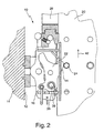
- Fig. 2 shows a snapshot of the climbing rail 20, as it is moved over the climbing cylinder 20 along a wall 12 of the concreting section 14 in the direction of arrow 42 upwards.
- the piston of the climbing cylinder 26 is extended, which also has a pawl at its free end, which engage under the support pin 24 of the climbing rail 20 and can wear.
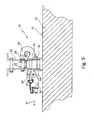
- Fig. 3 shows the climbing shoe 10 of Fig. 1 and 2 on the wall 12 of the concreting section 14, as the pawl 22 penetrateverschwenkt about the pivot point 36 under the pressure of the spring 38 to its original position.
- the climbing rail 20 was moved on the climbing cylinder 26 in the direction of arrow 42 on, so that the support pin 24 has released the pawl 22 again and this could swing back to its original position.
- Fig. 4 shows in plan view a climbing shoe 10, which is composed of a Gleitschuhteil 16 and a wall shoe part 18, as it is fixedly attached to the wall 12 of the concreting section 14.
- the sliding shoe 16 is pivotally connected to the wall shoe part 18.
- the claws 50 engage around the legs of the U-shaped profile of the climbing rail 20 and hold the climbing rail 20 guided on the wall 12.
- pawls 22 of the Gleitschuhteils 16 engage under the support pin 24 on one side of the climbing rail 20.
- the propeller shaft 30 to Placing a climbing cylinder arranged.
- One half of the jaws 50 is pivotable about an axis 54, provided that a Absteckbolzen 56 is pulled out of its holder, which prevents a possible pivotal movement of the left jaw 50.
- Fig. 5 shows the climbing shoe 10 of Fig. 4 with a claw 50 swung open on one side.
- a claw 50 of the shoe part 16 can be pivoted when the Absteckbolzen 56 brought out of engagement by a rigid wall portion of the Gleitschuhteils 16 is pulled out of a breakthrough in the claw 50. If the unlocking is released, the claw 50 can be pivoted about the axis 54. When the claw 50 is swung open, the locking pin 56 can be inserted again into its position locking the claw 50, and it is then ensured that the claw 50 remains in the state shown in the figure.
- the plug-in shaft 34 between the sliding-shoe part 16 and the wall-shoe part 18 is subsequently removed by pulling it out of the common mounting in the direction of the arrow 57, the sliding-shoe part 16 can be removed from the climbing rail 20 become. Subsequently, if necessary, even the wall shoe part 18 can be released from the anchor point in the wall 12 and removed.
- Fig. 6 shows a side view of a gimbal mounted climbing shoe 10 on the wall 12 of the concreting section 14.
- the sliding shoe 16 is hingedly connected via the stub shaft 34 with the wall shoe part 18 in the horizontal direction.
- the wall shoe part 18 has a vertically oriented axis 58 around which the wall shoe part 18 can be deflected with the sliding shoe part 16 as required.
- the tab 52 is formed, which carries the propeller shaft 30.
- the claws 50 hide the pawls 50 arranged between the claws.
- Fig. 7 shows the gimbal mounted climbing shoe 10 of Fig. 6 in plan view.
- the climbing shoe 10 is held stationary on the wall 12 of the concreting section 14 and can pivot about the vertically oriented axis 58 and about the horizontally oriented axis formed by the stub shaft 34.
- the sliding shoe part 16 is pivotably held on the wall shoe part 18 via the stub shaft 34, and the wall shoe part 18 can pivot over the axle 58 in itself.
- a claw 50 is pivotally mounted about the axis 54, wherein the Absteckbolzen 56 produces a rigid jaw connection between the Gleitschuhteil 16 and the pivoting jaw 50 in the set state. Between the claws 50, the pivotable pawls 22 are arranged in the sliding shoe 16.
- Fig. 8 shows a plan view of a concreting section 14 which is rounded.
- Anchor points provided on the concreting section 14 fasten the climbing shoes 10, which each guide a climbing rail 20 between the claws 50, and the climbing rails 20 are held in position via the lugs 20 provided in the climbing rails 20 via the latches arranged in the climbing shoes 10.
- consoles or rails 60 are attached, which via the gimbal mounted climbing shoes 10 always aligned parallel to the concreting section 14. If the brackets or rails 60 are always aligned parallel even with very different curvatures of the concreting section 14, 60 shuttering carriages can be moved toward the concreting section 14 or away from the concreting section 14 via the rails 60.
- About the vertically oriented axes 58 climbing shoes 10 are always aligned with the climbing rails 20 so that the brackets 60 and rails parallel to each other, and this regardless of the radius of curvature of a concreting section 14th
- a climbing shoe 10 of a climbing formwork for attachment to a concreting section 14 of a building has a sliding shoe part 16 on which claws 50 are provided. At least one claw 50 is pivotally and / or telescopically provided on the sliding shoe part 16.
Landscapes
- Engineering & Computer Science (AREA)
- Architecture (AREA)
- Structural Engineering (AREA)
- Mechanical Engineering (AREA)
- Civil Engineering (AREA)
- Life Sciences & Earth Sciences (AREA)
- Geology (AREA)
- Forms Removed On Construction Sites Or Auxiliary Members Thereof (AREA)
- Load-Engaging Elements For Cranes (AREA)
Description
- Die Erfindung betrifft einen Kletterschuh für eine Kletterschalung, welcher ein Wandschuhteil zur Befestigung des Kletterschuhs an einer Wandung eines Betonierabschnitts eines Bauwerks aufweist, wobei der Kletterschuh des Weiteren ein Gleitschuhteil aufweist, an dem Klauen vorgesehen sind, die derart ausgebildet sind, dass eine Kletterschiene zwischen den Klauen entlang der Wandung verschiebbar anordenbar ist und von den Klauen geführt gehalten werden kann, indem die Klauen derart ausgebildet sind, dass die Klauen Teilabschnitte einer Kletterschiene umgreifen können.
- Bekannt sind Kletterschuhe, die eine Kletterschiene umgreifen, derart, dass sie einerseits in den Kletterschuhen verschiebbar sind und andererseits die Kletterschienen an der Wandung eines Bauwerks geführt halten. Sollen die Kletterschuhe von einer Wandung abgenommen werden, so müssen die Kletterschienen aus den Kletterschuhen herausgefahren werden und anschließend ist es möglich, die an vorgesehenen Ankerstellen eines Betonierabschnitts befestigten Kletterschuhe abzubauen.
- Die
US 2003/052249 A1 beschreibt eine Kletterschalung mit Kletterschuhen. Eine Gerüsteinheit wird an Kletterschienen entlang einer Wandung eines Betonierabschnitts geführt. Die Kletterschienen sind ihrerseits verschiebbar in Kletterschuhen entlang der Wandung geführt. - Des Weiteren ist ein Kletterschuh z. B. durch die
Kr 1020020062259 A -
KR 20020047071 A - Aufgabe der Erfindung ist es, Kletterschuhe bereitzustellen, die von einer ortsfesten Befestigung an einem Betonierabschnitt einer Wandung auch dann abgenommen werden können, wenn sie von einer Kletterschiene durchgriffen sind.
- Gelöst wird die Aufgabe durch einen Kletterschuh mit den Merkmalen von Patentanspruch 1. Erfindungsgemäß weist der Kletterschuh ein Gleitschuhteil mit einer verschwenk- und/oder teleskopierbaren Klaue auf und das Gleitschuhteil ist mit dem Wandschuhteil, der an einer vertikal ausgerichteten Wandung befestigbar ist, des Kletterschuhs über eine horizontale und parallel zu der vertikalen Wandung ausgerichteten Steckwelle lösbar verbunden. Auf diese Weise ist der Abbau eines Kletterschuhs in einfacher Weise möglich, weil er neben der verschwenk- und/oder teleskopierbaren Klaue auch noch zusätzlich geteilt werden kann.
- Der erfindungsgemäße Kletterschuh kann unter mehreren an einem Bauwerk angebrachten Kletterschuhen immer schon dann von einer Wandung abgenommen werden, wenn er im Einsatz für die vorgesehene Kletterschalung nicht mehr benötigt wird. Dies ist immer dann der Fall, wenn ein Betonierabschnitt abgeschlossen ist und ein neuer Betonierabschnitt erstellt werden soll. Die für eine Kletterschalung verwendeten Kletterschienen weisen eine Länge auf, die größer ist als die Höhe von zwei zu erstellenden Betonierabschnitten. Somit müssen die untersten Kletterschuhe immer so lange an einer zu erstellenden Wandung verbleiben, bis die Kletterschienen soweit hochgeklettert sind, dass sie die untersten Kletterschuhe vollkommen freigeben. Sind die Kletterschienen außer Eingriff mit den Kletterschuhen, so können diese Kletterschuhe abgebaut werden. Zum Abbau dieser aus dem Stand der Technik bekannten Kletterschuhe sind in der Regel Hilfsbühnen bzw. Nachlaufbühnen notwendig und für das funktionsgerechte Betreiben einer aus dem Stand der Technik bekannten Kletterschalung ist eine größere Bevorratung von Kletterschuhen notwendig, damit die bekannten Kletterschalungen betrieben werden können.
- Werden erfindungsgemäße Kletterschuhe eingesetzt, so erübrigen sich zusätzliche Nachlaufbühnen zum Abbau nicht mehr benötigter Kletterschuhe, weil diese Kletterschuhe schon von einer Wandung abgebaut werden können, während sie noch im Eingriff mit den Kletterschienen stehen. Bei Bedarf kann der erfindungsgemäße Kletterschuh auch an einer beliebigen Stelle an eine Kletterschiene angebaut werden. Alle Vorteile, die sich beim Abbau eines Kletterschuhs von einer Kletterschiene ergeben, lassen sich auch auf den Einbau eines Kletterschuhs an eine Kletterschiene übertragen.
- Eine besondere Ausgestaltung eines Kletterschuhs ermöglicht den Ausbau des Kletterschuhs dann, wenn zwei Klauen eines Kletterschuhs die Kletterschiene in Teilabschnitten umgreifen und eine Klaue verschwenkbar am Gleitschuhteil vorgesehen ist. Ein verschwenkbares Lager ist einfach und kostengünstig an einer Klaue des Gleitschuhs auszubilden und die Schwenkbewegung kann einfachst über einen Absteckbolzen arretiert werden. Wird der Absteckbolzen entfernt, so kann die Klaue aufgeschwenkt werden und von der Kletterschiene abgenommen werden. Ist die Klaue aufgeschwenkt, so kann sie ebenfalls über den gleichen Absteckbolzen blockiert werden, so dass sichergestellt ist, dass beim Ausbau der verschwenkbaren Klaue diese nicht unkontrolliert verschwenkt.
- In weiterer Ausgestaltung der Erfindung weist der Kletterschuh im Wandschuhteil eine vertikal ausgerichtete Achse auf. Dies hat den Vorteil, dass sich der Kletterschuh auch an gerundeten Wandungen von Betonierabschnitten derart ausrichten kann, dass benachbarte Kletterschuhe in den Kletterschuhen gehaltene Kletterschienen und damit verbundene Konsolen immer parallel zueinander verlaufend ausrichten. Dies hat den Vorteil, dass auf den Konsolen bzw. Schienen Fahrwagen, die beispielsweise Schalungswände aufnehmen, an die Wandung herangefahren oder von der Wandung weggefahren werden können.
- In den nachfolgenden Fign. wird in einem Ausführungsbeispiel der erfindungsgemäße Kletterschuh gezeigt und beschrieben.
- Es zeigt:
- Fig. 1
- einen Schnitt durch einen erfindungsgemäßen Kletterschuh, wie er an einer betonierten Wandung ortsfest angebracht ist, und eine Kletterschiene unverrückbar führt und hält;
- Fig. 2
- einen Schnitt durch einen erfindungsgemäßen Kletterschuh mit in den Kletterschuh eingeschwenkter Klinke;
- Fig. 3
- einen Schnitt durch einen erfindungsgemäßen Kletterschuh gemäß
Fig. 1 und2 mit aus dem Kletterschuh ausgeschwenkter Klinke und frei von einem Eingriff mit einem Tragbolzen; - Fig. 4
- einen Kletterschuh in Draufsicht, wie er an einem Betonierabschnitt befestigt ist und mit Klauen eine Kletterschiene umgreift;
- Fig. 5
- einen Kletterschuh in Draufsicht, wie er an einem Betonierabschnitt einer Wandung befestigt ist mit einseitig geöffneter Klaue zum Abnehmen von einer Kletterschiene;
- Fig. 6
- eine Seitenansicht eines Kletterschuhs, wie er an der Wandung eines Betonierabschnitts ortsfest befestigt ist, mit einer kardanischen Lagerung um eine horizontal und vertikal ausgerichtete Achse;
- Fig. 7
- eine Draufsicht auf einen Kletterschuh gemäß
Fig. 6 ; und - Fig. 8
- kardanisch gelagerte und ortsfest befestigte Kletterschuhe an einer konvex ausgebildeten Wandung eines Betonierabschnitts mit Kletterschienen, die Konsolen bzw. Schienenelemente parallel ausgerichtet halten.
- Die Figuren zeigen die erfindungsgemäßen Ausbildungen stark schematisiert und sind nicht maßstäblich zu verstehen.
- Gleiche Funktionselemente sind in den nachfolgend beschriebenen Figuren weitestgehend mit den gleichen Bezugszeichen gekennzeichnet. Diese Funktionselemente können gegenständlich unterschiedlichst ausgestaltet sein.
Fig. 1 zeigt in einer Seitenansicht und teilweise geschnitten einen Kletterschuh 10, wie er an einer Wandung 12 eines Betonierabschnitts 14 ortsfest an einer Ankerstelle angebracht ist. Der Kletterschuh 10 setzt sich aus einem Gleitschuhteil 16 und aus einem Wandschuhteil 18 zusammen. Eine Kletterschiene 20 wird über eine Klinke 22 des Gleitschuhteils 16 getragen und seitlich geführt, indem die Klinke 22 einen Tragbolzen 24 der Kletterschiene 20 untergreift. Die Klinke 22 ist in ihrer maximal möglichen Auslenkung gezeigt und gegenständlich ausgebildete Gegenlager innerhalb des Gleitschuhteils 16 verhindern eine weitere Auslenkung der Klinke 22 im Uhrzeigersinn. - Auf das Gleitschuhteil 16 des Kletterschuhs 10 ist ein Kletterzylinder 26 aufgesetzt. Von dem Kletterzylinder 26 ist nur der unterste Teil des Zylinders zu sehen, an den sich ein Gehäuse 28 anschließt, über das der Kletterzylinder 26 auf eine Gelenkwelle 30 des Kletterschuhs 10 aufgesteckt ist. Ein Sicherheitsbolzen 32 fixiert das Gehäuse 28 an der Gelenkwelle 30 ohne den Verschwenkbereich des Kletterzylinders 26 um die Gelenkwelle 30 zu behindern. Wird der Sicherheitsbolzen 32 gegen eine Federkraft aus dem Eingriff zur Gelenkwelle 30 gezogen, kann der Kletterzylinder 26 von der Gelenkwelle 30 abgezogen werden. Das Gehäuse 28 des Kletterzylinders 26 stützt sich über ein gummi- oder zähelastisches Element 33 auf einer Gehäusewandung des Gleitschuhteils 16 ab.
- Das Gleitschuhteil 16 ist über eine Steckwelle 34, die horizontal ausgerichtet ist, mit dem Wandschuhteil 18 gelenkig verbunden. Um die Steckwelle 34 kann das Gleitschuhteil 16 gegenüber dem Wandschuhteil 18 verschwenkt werden.
- Innerhalb des Gleitschuhteils 16 ist die Klinke 22 um einen Drehpunkt 36 gegen den Druck einer Feder 38 entgegen dem Uhrzeigersinn verschwenkbar.
- Wird die Klinke 22 nicht über Tragbolzen 24 der Kletterschiene 20 gewichtsbelastet, so kann die Klinke 22 gegen den Druck der Feder 38 von Hand über den Hebel 40 in das Gleitschuhteil 16 verschwenkt werden. Dies ist immer dann notwendig, wenn die Kletterschiene 20 gegenüber dem ortsfest angeordneten Kletterschuh 10 nach unten verfahren werden soll.
- Von dem Betonierabschnitt 14, der Kletterschiene 20 und dem Kletterzylinder 26 sind in der Figur nur kleine Ausschnitte gezeigt.
-
Fig. 2 zeigt eine Momentaufnahme der Kletterschiene 20, wie sie über den Kletterzylinder 20 entlang einer Wandung 12 des Betonierabschnitts 14 in Pfeilrichtung 42 nach oben verschoben wird. Für diesen Klettervorgang der Kletterschiene 20 in Pfeilrichtung 42 wird der Kolben des Kletterzylinders 26 ausgefahren, der an seinem freien Ende ebenfalls eine Klinke aufweist, die den Tragbolzen 24 der Kletterschiene 20 untergreifen und tragen kann. - Wird die Kletterschiene 20 über den Kletterzylinder 26 in Pfeilrichtung 42 verfahren, so drückt ein Tragbolzen 24 der Kletterschiene 20 auf eine Auflaufschräge 44 der Klinke 22 und verschwenkt die Klinke 22 um den Drehpunkt 36 gegen den Druck der Feder 38. Die Klinke 22 verschwenkt dabei in das Gleitschuhteil 16 des Kletterschuhs 10.
-
Fig. 3 zeigt den Kletterschuh 10 derFig. 1 und2 an der Wandung 12 des Betonierabschnitts 14, wie die Klinke 22 um den Drehpunkt 36 unter dem Druck der Feder 38 in ihre Ausgangslage zurückverschwenkt. Die Kletterschiene 20 wurde über den Kletterzylinder 26 in Pfeilrichtung 42 weiter verfahren, so dass der Tragbolzen 24 die Klinke 22 wieder freigegeben hat und diese in ihre Ausgangsstellung zurückschwenken konnte. - Wird der Kletterzylinder 26 eingefahren, so setzt sich der Tragbolzen 24 auf der Klinke 22 ab und der Kletterschuh 10 hält die Kletterschiene 20 in der in der Figur gezeigten Position an der Wandung 12 des Betonierabschnitts 14.
-
Fig. 4 zeigt in Draufsicht einen Kletterschuh 10, der sich aus einem Gleitschuhteil 16 und einem Wandschuhteil 18 zusammensetzt, wie er ortsfest an der Wandung 12 des Betonierabschnitts 14 befestigt ist. Über die Steckwelle 34 ist das Gleitschuhteil 16 gelenkig mit dem Wandschuhteil 18 verbunden. Die Klauen 50 umgreifen die Schenkel des U-förmigen Profils der Kletterschiene 20 und halten die Kletterschiene 20 geführt an der Wandung 12. Klinken 22 des Gleitschuhteils 16 untergreifen den Tragbolzen 24 auf einer Seite der Kletterschiene 20. Auf dem Gleitschuhteil 16 ist die Gelenkwelle 30 zum Aufstecken eines Kletterzylinders angeordnet. Eine Hälfte der Klauen 50 ist um eine Achse 54 verschwenkbar, sofern ein Absteckbolzen 56 aus seiner Halterung herausgezogen wird, der eine mögliche Schwenkbewegung der linken Klaue 50 verhindert. -
Fig. 5 zeigt den Kletterschuh 10 vonFig. 4 mit auf einer Seite aufgeschwenkter Klaue 50. - Soll ein Kletterschuh 10 an einer Wandung 12 des Betonierabschnitts 14 auch bei Anwesenheit der Kletterschiene 20 aus- bzw. abgebaut werden, so kann eine Klaue 50 des Gleitschuhteils 16 aufgeschwenkt werden, wenn der Absteckbolzen 56 aus dem Eingriff von einem starren Wandabschnitt des Gleitschuhteils 16 gebracht wird und aus einem Durchbruch in der Klaue 50 herausgezogen wird. Ist die Entriegelung gelöst, so kann die Klaue 50 um die Achse 54 verschwenkt werden. Ist die Klaue 50 aufgeschwenkt, so kann der Absteckbolzen 56 wieder in seine die Klaue 50 verriegelnde Position eingesteckt werden, und es ist dann gewährleistet, dass die Klaue 50 im in der Figur gezeigten Zustand verbleibt. Wird anschließend noch die Steckwelle 34 zwischen dem Gleitschuhteil 16 und dem Wandschuhteil 18 entfernt, indem man sie in Pfeilrichtung 57 aus der gemeinsamen Lagerung herauszieht, so kann das Gleitschuhteil 16 von der Kletterschiene 20 entfernt werden. Anschließend kann bei Bedarf auch noch das Wandschuhteil 18 von der Ankerstelle in der Wandung 12 gelöst und abgenommen werden.
-
Fig. 6 zeigt eine Seitenansicht eines kardanisch gelagerten Kletterschuhs 10 an der Wandung 12 des Betonierabschnitts 14. Das Gleitschuhteil 16 ist über die Steckwelle 34 mit dem Wandschuhteil 18 in horizontaler Richtung gelenkig verbunden. Zusätzlich zu den Kletterschuhen aus denFig. 1 bis 5 weist das Wandschuhteil 18 eine vertikal ausgerichtete Achse 58 auf, um die das Wandschuhteil 18 mit dem Gleitschuhteil 16 bei Bedarf ausgelenkt werden kann. Am Gleitschuhteil 16 ist die Lasche 52 ausgebildet, die die Gelenkwelle 30 trägt. Die Klauen 50 verdecken die zwischen den Klauen 50 angeordneten Klinken. -
Fig. 7 zeigt den kardanisch gelagerten Kletterschuh 10 derFig. 6 in Draufsicht. Der Kletterschuh 10 ist an der Wandung 12 des Betonierabschnitts 14 ortsfest gehalten und kann um die vertikal ausgerichtete Achse 58 und um die horizontal ausgerichtete Achse, die von der Steckwelle 34 gebildet wird, verschwenken. Das Gleitschuhteil 16 ist verschwenkbar am Wandschuhteil 18 über die Steckwelle 34 gehalten und über die Achse 58 kann das Wandschuhteil 18 in sich verschwenken. Eine Klaue 50 ist um die Achse 54 verschwenkbar gelagert, wobei der Absteckbolzen 56 im gesetzten Zustand eine starre Klauenverbindung zwischen dem Gleitschuhteil 16 und der verschwenkbaren Klaue 50 herstellt. Zwischen den Klauen 50 sind die verschwenkbaren Klinken 22 im Gleitschuhteil 16 angeordnet. -
Fig. 8 zeigt in einer Draufsicht einen Betonierabschnitt 14, der gerundet ausgebildet ist. An am Betonierabschnitt 14 vorgesehenen Ankerstellen sind die Kletterschuhe 10 befestigt, die jeweils zwischen den Klauen 50 eine Kletterschiene 20 führen, und über die in den Kletterschuhen 10 angeordneten Klinken werden die Kletterschienen 20 über die in den Kletterschienen 20 vorgesehenen Tragbolzen 24 in Position gehalten. An den Kletterschienen 20 sind Konsolen bzw. Schienen 60 befestigt, die über die kardanisch gelagerten Kletterschuhe 10 immer parallel ausgerichtet am Betonierabschnitt 14 verlaufen. Sind die Konsolen bzw. Schienen 60 auch bei unterschiedlichsten Krümmungen des Betonierabschnitts 14 stets parallel ausgerichtet, so können über die Schienen 60 Schalungswagen an den Betonierabschnitt 14 heran- bzw. von dem Betonierabschnitt 14 weg verfahren werden. Über die vertikal ausgerichteten Achsen 58 werden die Kletterschuhe 10 mit den Kletterschienen 20 stets so ausgerichtet, dass die Konsolen 60 bzw. Schienen parallel zueinander verlaufen, und dies unabhängig vom Krümmungsradius eines Betonierabschnitts 14. - Ein Kletterschuh 10 einer Kletterschalung zur Befestigung an einem Betonierabschnitt 14 eines Bauwerks weist ein Gleitschuhteil 16 auf, an dem Klauen 50 vorgesehen sind. Mindestens eine Klaue 50 ist schwenkbar und/oder teleskopierbar am Gleitschuhteil 16 vorgesehen.
Claims (4)
- Kletterschuh für eine Kletterschalung, mit einem Wandschuhteil (18) und einem Gleitschuhteil (16), wobei der Wandschuhteil (18) zur Befestigung an einer vertikal ausgerichteten Wandung (12) eines Betonierabschnitts (14) eines Bauwerks ausgebildet ist, wobei am Gleitschuhteil (16) Klauen (50) vorgesehen sind, die derart ausgebildet sind, dass eine Kletterschiene (20) zwischen den Klauen (50) verschiebbar anordenbar ist und von den Klauen (50) geführt gehalten werden kann, indem die Klauen (50) derart ausgebildet sind, dass die Klauen (50) Teilabschnitte einer Kletterschiene (20) umgreifen können, und wobei mindestens eine Klaue (50) verschwenk- und/oder teleskopierbar am Gleitschuhteil (16) vorgesehen ist, welcher mit dem Wandschuhteil (18) über eine horizontale und parallel zu der vertikalen Wandung ausgerichteten Steckwelle (34) lösbar verbunden ist.
- Kletterschuh nach Anspruch 1, dadurch gekennzeichnet, dass zwei Klauen (50) des Kletterschuhs (10) derart ausgebildet sind, dass die Klauen (50) Teilabschnitte einer Kletterschiene (20) umgreifen können, und dass eine Klaue (50) verschwenkbar am Gleitschuhteil (16) befestigt ist.
- Kletterschuh nach Anspruch 2, dadurch gekennzeichnet, dass die Schwenkbewegung sowohl im geschlossenen als auch im aufgeschwenkten Zustand der Klaue (50) über einen Absteckbolzen (56) blockierbar ist.
- Kletterschuh nach einem der Ansprüche 1 bis 3, dadurch gekennzeichnet, dass das Wandschuhteil (18) des Kletterschuhs (10) eine vertikal ausgerichtete Achse (58) aufweist.
Priority Applications (1)
| Application Number | Priority Date | Filing Date | Title |
|---|---|---|---|
| PL06761666T PL1899548T3 (pl) | 2005-06-29 | 2006-06-20 | Dzielony ślizg przesuwny dla deskowania przesuwnego |
Applications Claiming Priority (2)
| Application Number | Priority Date | Filing Date | Title |
|---|---|---|---|
| DE102005030333.1A DE102005030333C5 (de) | 2005-06-29 | 2005-06-29 | Teilbarer Kletterschuh einer Kletterschalung |
| PCT/DE2006/001045 WO2007000136A1 (de) | 2005-06-29 | 2006-06-20 | Teilbarer kletterschuh einer kletterschalung |
Publications (2)
| Publication Number | Publication Date |
|---|---|
| EP1899548A1 EP1899548A1 (de) | 2008-03-19 |
| EP1899548B1 true EP1899548B1 (de) | 2015-01-28 |
Family
ID=37106477
Family Applications (1)
| Application Number | Title | Priority Date | Filing Date |
|---|---|---|---|
| EP06761666.4A Active EP1899548B1 (de) | 2005-06-29 | 2006-06-20 | Teilbarer kletterschuh einer kletterschalung |
Country Status (11)
| Country | Link |
|---|---|
| US (1) | US8714512B2 (de) |
| EP (1) | EP1899548B1 (de) |
| JP (1) | JP4809891B2 (de) |
| KR (1) | KR100707547B1 (de) |
| AU (1) | AU2006264099B9 (de) |
| CA (1) | CA2613151C (de) |
| DE (1) | DE102005030333C5 (de) |
| ES (1) | ES2532911T3 (de) |
| PL (1) | PL1899548T3 (de) |
| RU (1) | RU2369703C1 (de) |
| WO (1) | WO2007000136A1 (de) |
Cited By (2)
| Publication number | Priority date | Publication date | Assignee | Title |
|---|---|---|---|---|
| CN104695693A (zh) * | 2015-03-02 | 2015-06-10 | 赵金海 | 一种液压爬升式外墙脚手架 |
| DE102022214177A1 (de) | 2022-07-20 | 2024-01-25 | Hünnebeck GmbH | Kletterschuh, Klinkenvorrichtung, Befestigungsteil und Verfahren |
Families Citing this family (36)
| Publication number | Priority date | Publication date | Assignee | Title |
|---|---|---|---|---|
| DE102006026201B4 (de) * | 2006-06-06 | 2008-04-10 | Doka Industrie Gmbh | Selbstklettersystem |
| DE102007018851A1 (de) * | 2007-04-20 | 2008-10-30 | Doka Industrie Gmbh | Führungsschuh und Kombination eines Führungsschuhs mit einem Kletterprofil |
| KR100927258B1 (ko) | 2007-11-07 | 2009-11-16 | 금강공업 주식회사 | 가설대 승강장치 |
| KR100927259B1 (ko) | 2007-11-07 | 2009-11-16 | 금강공업 주식회사 | 가설대 승강장치 |
| DE102008015682A1 (de) | 2008-03-25 | 2009-10-08 | Peri Gmbh | Schienengeführtes Selbstkletterschalungssystem mit Kletterschienen-Verlängerungsstücken |
| KR100895614B1 (ko) * | 2008-06-16 | 2009-05-06 | 이송복 | 건축물 시공방법 |
| AT510500B1 (de) * | 2009-07-21 | 2013-07-15 | Tms Tuefekcioglu Muehendislik Sanayi Ve Ticaret Anonim Sirketi | Trägerkopf mit bolzenmechanismus für mit kolben angetriebene klettersysteme |
| PL2365159T3 (pl) | 2010-03-05 | 2013-07-31 | Ulma C Y E S Coop | Samowznoszący, obwodowy system zabezpieczania dla prac budowlanych w budynkach |
| KR101297572B1 (ko) * | 2011-02-25 | 2013-08-20 | 한국산업안전보건공단 | Rcs 안전봉 |
| ES2568578T3 (es) | 2011-04-28 | 2016-04-29 | Ulma C Y E, S. Coop. | Cabezal trepador para elevar un sistema de protección autotrepante para trabajos de construcción en edificios |
| CN102352685A (zh) * | 2011-07-29 | 2012-02-15 | 中国葛洲坝集团股份有限公司 | 液压升降式施工平台 |
| US8757593B2 (en) | 2012-05-10 | 2014-06-24 | Commonwealth Dynamics, Inc. | Ratchet pawl system, device and method |
| AU2014224104B2 (en) * | 2013-09-10 | 2020-04-23 | Evan Zannis | Construction Site Safety Screen System |
| US9963889B2 (en) * | 2013-12-17 | 2018-05-08 | Shenzhen Techen Technology Co., Ltd | Sealed and integrated climbing scaffold and method for using the same |
| CN104563501B (zh) * | 2014-05-14 | 2018-10-09 | 山东国兴模板脚手架有限公司 | 建筑设施附墙挂座的使用方法 |
| ES2834884T3 (es) | 2014-08-27 | 2021-06-21 | Doka Gmbh | Dispositivo y procedimiento para guiar un soporte para un elemento de encofrado o de protección |
| GB2533142B (en) * | 2014-12-11 | 2019-08-14 | Ischebeck Titan Ltd | Hook arrangement |
| US10465401B2 (en) * | 2015-04-15 | 2019-11-05 | Ronald A. Bullock | Construction safety net support apparatus |
| DE102016205956A1 (de) * | 2016-04-08 | 2017-10-12 | Peri Gmbh | Selbstklettersystem, Selbstklettereinheit sowie Verfahren zum Umsetzen einer solchen Selbstklettereinheit an einem Betonbaukörper |
| CN105780728A (zh) * | 2016-04-26 | 2016-07-20 | 南通铁军机械有限公司 | 一种航道墙体式护岸整体自动震捣滑模装置 |
| ES2705718T3 (es) | 2016-05-04 | 2019-03-26 | Ulma C Y E S Coop | Cabeza trepante para fijar un andamio trepante a una sección de hormigón de un edificio en construcción |
| DE102016220051A1 (de) * | 2016-10-14 | 2018-04-19 | Peri Gmbh | Konsolgerüst |
| DE102017202264A1 (de) | 2017-02-13 | 2018-08-16 | Peri Gmbh | Klettervorrichtung zum Absenken einer Kletterschiene und Verfahren zum Absenken einer Kletterschiene |
| US11053699B2 (en) * | 2017-10-27 | 2021-07-06 | Doka Gmbh | Climbing shoe, safety screen support system and safety screen system |
| IL257315B (en) * | 2018-02-01 | 2022-08-01 | Sba Metal Works Ltd | Mechanism for climbing scaffolding |
| DE102018202097A1 (de) | 2018-02-12 | 2019-08-14 | Peri Gmbh | Klettersystem und Verfahren zum Betrieb eines Klettersystems |
| DE102018204961A1 (de) | 2018-04-03 | 2019-10-10 | Peri Gmbh | Selbstklettersystem mit Antrieb über ein umlaufendes Antriebsmittel und Verfahren zum Betrieb eines Selbstklettersystems |
| KR102069702B1 (ko) * | 2018-09-14 | 2020-01-23 | 주식회사 선진알씨에스 | 건물 벽체 공사용 클라이밍 장치 |
| DE102019104548A1 (de) * | 2019-02-22 | 2020-08-27 | Peri Gmbh | Hubantrieb für ein schienengeführtes freivorbaugerät |
| DE102019115346A1 (de) * | 2019-06-06 | 2020-12-10 | Peri Gmbh | Anordnung von einer kletterschiene und einer kletterhubschiene für ein schienengeführtes klettersystem |
| US11655641B2 (en) * | 2019-12-29 | 2023-05-23 | The Third Construction Co., Ltd Of China Construction Third Engneering Bureau | Construction building equipment and construction method thereof |
| CN112144402B (zh) * | 2020-09-03 | 2022-04-15 | 浙江精工钢结构集团有限公司 | 一种旋转顶升方法 |
| DE102020214455A1 (de) | 2020-11-17 | 2022-05-19 | Doka Gmbh | Klettergerüst |
| DE102020134813A1 (de) | 2020-12-23 | 2022-06-23 | Peri Se | Kletterschuh für ein schienengeführtes Klettersystem |
| DE102020134812A1 (de) | 2020-12-23 | 2022-06-23 | Peri Se | Kletterschuhvorrichtung für ein schienengeführtes Klettersystem |
| CN113147939B (zh) * | 2021-03-23 | 2022-06-07 | 中建三局集团有限公司 | 行程可调间歇式顶模爬升系统及其爬升框和爬升方法 |
Citations (2)
| Publication number | Priority date | Publication date | Assignee | Title |
|---|---|---|---|---|
| KR20020047071A (ko) * | 2002-05-11 | 2002-06-21 | 손경식 | 건축장의 레일난간(비계) 협지장치. |
| KR20020062259A (ko) * | 2002-05-06 | 2002-07-25 | 웨이 펀 츄 | 레일 브래킷 조립체 및 이를 이용한 수직 이동형 비계 |
Family Cites Families (15)
| Publication number | Priority date | Publication date | Assignee | Title |
|---|---|---|---|---|
| FR2298662A1 (fr) | 1975-01-27 | 1976-08-20 | St Amand Outinord | Coffrage auto-relevable |
| DE2814930C2 (de) | 1978-04-06 | 1986-07-03 | Peri-Werk Artur Schwörer GmbH & Co KG, 7912 Weißenhorn | Klettergerüst |
| DE3006491C2 (de) | 1980-02-21 | 1983-01-05 | Streif AG, 5461 Vettelschoß | Versetzbares, an einem Bauwerk verankertes Gerüst |
| FR2487410A1 (fr) * | 1980-07-24 | 1982-01-29 | Bouygues Sa | Coffrage grimpant pour la coulee de parois en beton |
| FR2487892A1 (fr) * | 1980-08-01 | 1982-02-05 | Huennebeck Gmbh | Appareil a dispositif elevateur pour grimper le long d'une paroi, notamment pour echafaudage grimpant |
| SU968262A1 (ru) | 1981-03-11 | 1982-10-23 | Проектный и научно-исследовательский институт "Донецкий ПромстройНИИпроект" | Подъемно-переставна опалубка |
| DE3844977C2 (de) | 1988-12-14 | 1997-10-23 | Peri Werk Schwoerer Kg Artur | Kletterschalungs-Verschiebebühne und Verfahren zu deren Betrieb |
| US4892169A (en) * | 1989-02-21 | 1990-01-09 | Sinco, Inc. | Perimeter debris net lifting system |
| DE4302197A1 (de) | 1993-01-27 | 1994-07-28 | Peri Gmbh | Klettervorrichtung, insbesondere für ein Klettergerüst |
| RU2078884C1 (ru) | 1993-03-01 | 1997-05-10 | Нижегородский архитектурно-строительный институт | Способ возведения монолитного здания и подвижная опалубка для его осуществления |
| US6557817B2 (en) * | 2000-01-18 | 2003-05-06 | Wilian Holding Company | Wall climbing form hoist |
| AU2002951070A0 (en) | 2002-08-29 | 2002-09-12 | Formula One Self Driving Screens Pty Ltd | A lifting or transporting means using a reciprocating jack |
| KR200355424Y1 (ko) | 2004-04-23 | 2004-07-06 | 금강공업 주식회사 | 상승식 가설대용 안내장치 |
| KR200393396Y1 (ko) | 2005-04-11 | 2005-08-22 | 금강공업 주식회사 | 상승식 가설대용 안내장치의 안내 걸림 슈 |
| KR200391342Y1 (ko) | 2005-04-30 | 2005-08-02 | 삼목정공주식회사 | 건축용 갱폼의 가이드레일 고정장치 |
-
2005
- 2005-06-29 DE DE102005030333.1A patent/DE102005030333C5/de not_active Expired - Fee Related
-
2006
- 2006-06-20 EP EP06761666.4A patent/EP1899548B1/de active Active
- 2006-06-20 CA CA2613151A patent/CA2613151C/en not_active Expired - Fee Related
- 2006-06-20 US US11/993,024 patent/US8714512B2/en active Active
- 2006-06-20 WO PCT/DE2006/001045 patent/WO2007000136A1/de not_active Ceased
- 2006-06-20 ES ES06761666.4T patent/ES2532911T3/es active Active
- 2006-06-20 JP JP2008518612A patent/JP4809891B2/ja not_active Expired - Fee Related
- 2006-06-20 RU RU2008103263/03A patent/RU2369703C1/ru active
- 2006-06-20 PL PL06761666T patent/PL1899548T3/pl unknown
- 2006-06-20 AU AU2006264099A patent/AU2006264099B9/en not_active Ceased
- 2006-06-28 KR KR1020060058914A patent/KR100707547B1/ko active Active
Patent Citations (2)
| Publication number | Priority date | Publication date | Assignee | Title |
|---|---|---|---|---|
| KR20020062259A (ko) * | 2002-05-06 | 2002-07-25 | 웨이 펀 츄 | 레일 브래킷 조립체 및 이를 이용한 수직 이동형 비계 |
| KR20020047071A (ko) * | 2002-05-11 | 2002-06-21 | 손경식 | 건축장의 레일난간(비계) 협지장치. |
Cited By (2)
| Publication number | Priority date | Publication date | Assignee | Title |
|---|---|---|---|---|
| CN104695693A (zh) * | 2015-03-02 | 2015-06-10 | 赵金海 | 一种液压爬升式外墙脚手架 |
| DE102022214177A1 (de) | 2022-07-20 | 2024-01-25 | Hünnebeck GmbH | Kletterschuh, Klinkenvorrichtung, Befestigungsteil und Verfahren |
Also Published As
| Publication number | Publication date |
|---|---|
| RU2369703C1 (ru) | 2009-10-10 |
| AU2006264099A1 (en) | 2007-01-04 |
| AU2006264099B2 (en) | 2009-12-17 |
| US20090146041A1 (en) | 2009-06-11 |
| WO2007000136A1 (de) | 2007-01-04 |
| US8714512B2 (en) | 2014-05-06 |
| CA2613151C (en) | 2011-03-01 |
| AU2006264099B9 (en) | 2010-03-18 |
| EP1899548A1 (de) | 2008-03-19 |
| RU2008103263A (ru) | 2009-08-10 |
| DE102005030333C5 (de) | 2017-09-28 |
| DE102005030333B4 (de) | 2010-04-22 |
| PL1899548T3 (pl) | 2015-06-30 |
| JP2008545073A (ja) | 2008-12-11 |
| JP4809891B2 (ja) | 2011-11-09 |
| KR20060087483A (ko) | 2006-08-02 |
| ES2532911T3 (es) | 2015-04-01 |
| KR100707547B1 (ko) | 2007-04-13 |
| CA2613151A1 (en) | 2007-01-04 |
| DE102005030333A1 (de) | 2007-01-04 |
Similar Documents
| Publication | Publication Date | Title |
|---|---|---|
| DE102005030333B4 (de) | Teilbarer Kletterschuh einer Kletterschalung | |
| EP1902185B2 (de) | Kletterschalung mit angelenktem kletterschuh | |
| EP3337752B1 (de) | Mobilkran und verfahren zum abwinkeln einer hauptauslegerverlängerung relativ zu einem hauptausleger eines mobilkrans | |
| WO2007000134A1 (de) | Kletterzylinder einer selbstkletterschalung | |
| EP4267816B1 (de) | Kletterschuh für ein schienengeführtes klettersytem | |
| EP3580407B1 (de) | Klettervorrichtung zum absenken einer kletterschiene und verfahren zum absenken einer kletterschiene | |
| EP3527428A1 (de) | Dachträger | |
| DE102018203612A1 (de) | Absenkeinrichtung sowie Stützvorrichtung und Deckenschalung mit einer solchen Absenkeinrichtung | |
| DE102017110586A1 (de) | Schnellwechsler und Schnellwechselsystem mit einem derartigen Schnellwechsler | |
| DE102016106533A1 (de) | Sicherungssäule | |
| EP2137365B1 (de) | Führungsschuh und kombination eines führungsschuhs mit einem kletterprofil | |
| EP0042608B1 (de) | Abstützeinrichtung für ein von einem Traktor abbaubares Arbeitsgerät | |
| WO2007000135A1 (de) | Bewegliches auflager eines kletterschuhs einer kletterschalung | |
| EP3032002B2 (de) | Combination von kletterkonsole und verschalungsteil | |
| DE2846819C2 (de) | ||
| DE102004039470B4 (de) | Betonschalungsschloss und Betonschalelement | |
| DE202013104849U1 (de) | Wandschalung mit Parkposition für ein Keilschloss | |
| EP4069919A1 (de) | Schalung | |
| DE19625613A1 (de) | Hebevorrichtung, insbesondere zum Heben von Deckeln von Unterflurhydranten | |
| EP4267815B1 (de) | Schienengeführtes klettersystem | |
| DE102010042954A1 (de) | Klapptisch | |
| DE10351255B4 (de) | Absenkvorrichtung für eine Tragkonstruktion | |
| DE102023004148A1 (de) | Greifvorrichtung zum Versetzen eines Flächenelements | |
| DE102024130866A1 (de) | Demontagevorrichtung für ein Geländer eines Arbeitsgerüsts | |
| DE20218531U1 (de) | Arbeitsplattformeinrichtung |
Legal Events
| Date | Code | Title | Description |
|---|---|---|---|
| PUAI | Public reference made under article 153(3) epc to a published international application that has entered the european phase |
Free format text: ORIGINAL CODE: 0009012 |
|
| 17P | Request for examination filed |
Effective date: 20080129 |
|
| AK | Designated contracting states |
Kind code of ref document: A1 Designated state(s): AT BE BG CH CY CZ DE DK EE ES FI FR GB GR HU IE IS IT LI LT LU LV MC NL PL PT RO SE SI SK TR |
|
| DAX | Request for extension of the european patent (deleted) | ||
| DAX | Request for extension of the european patent (deleted) | ||
| TPAC | Observations filed by third parties |
Free format text: ORIGINAL CODE: EPIDOSNTIPA |
|
| TPAC | Observations filed by third parties |
Free format text: ORIGINAL CODE: EPIDOSNTIPA |
|
| TPAC | Observations filed by third parties |
Free format text: ORIGINAL CODE: EPIDOSNTIPA |
|
| 17Q | First examination report despatched |
Effective date: 20140217 |
|
| GRAP | Despatch of communication of intention to grant a patent |
Free format text: ORIGINAL CODE: EPIDOSNIGR1 |
|
| INTG | Intention to grant announced |
Effective date: 20140908 |
|
| GRAS | Grant fee paid |
Free format text: ORIGINAL CODE: EPIDOSNIGR3 |
|
| GRAA | (expected) grant |
Free format text: ORIGINAL CODE: 0009210 |
|
| AK | Designated contracting states |
Kind code of ref document: B1 Designated state(s): AT BE BG CH CY CZ DE DK EE ES FI FR GB GR HU IE IS IT LI LT LU LV MC NL PL PT RO SE SI SK TR |
|
| REG | Reference to a national code |
Ref country code: GB Ref legal event code: FG4D Free format text: NOT ENGLISH |
|
| REG | Reference to a national code |
Ref country code: CH Ref legal event code: NV Representative=s name: RIEDERER HASLER AND PARTNER PATENTANWAELTE AG, LI Ref country code: CH Ref legal event code: EP |
|
| REG | Reference to a national code |
Ref country code: IE Ref legal event code: FG4D Free format text: LANGUAGE OF EP DOCUMENT: GERMAN |
|
| REG | Reference to a national code |
Ref country code: DE Ref legal event code: R096 Ref document number: 502006014184 Country of ref document: DE Effective date: 20150312 |
|
| REG | Reference to a national code |
Ref country code: AT Ref legal event code: REF Ref document number: 708325 Country of ref document: AT Kind code of ref document: T Effective date: 20150315 |
|
| REG | Reference to a national code |
Ref country code: ES Ref legal event code: FG2A Ref document number: 2532911 Country of ref document: ES Kind code of ref document: T3 Effective date: 20150401 |
|
| REG | Reference to a national code |
Ref country code: SE Ref legal event code: TRGR |
|
| REG | Reference to a national code |
Ref country code: FR Ref legal event code: PLFP Year of fee payment: 10 |
|
| REG | Reference to a national code |
Ref country code: LT Ref legal event code: MG4D |
|
| REG | Reference to a national code |
Ref country code: HU Ref legal event code: AG4A Ref document number: E022686 Country of ref document: HU |
|
| REG | Reference to a national code |
Ref country code: PL Ref legal event code: T3 |
|
| PG25 | Lapsed in a contracting state [announced via postgrant information from national office to epo] |
Ref country code: FI Free format text: LAPSE BECAUSE OF FAILURE TO SUBMIT A TRANSLATION OF THE DESCRIPTION OR TO PAY THE FEE WITHIN THE PRESCRIBED TIME-LIMIT Effective date: 20150128 Ref country code: LT Free format text: LAPSE BECAUSE OF FAILURE TO SUBMIT A TRANSLATION OF THE DESCRIPTION OR TO PAY THE FEE WITHIN THE PRESCRIBED TIME-LIMIT Effective date: 20150128 Ref country code: BG Free format text: LAPSE BECAUSE OF FAILURE TO SUBMIT A TRANSLATION OF THE DESCRIPTION OR TO PAY THE FEE WITHIN THE PRESCRIBED TIME-LIMIT Effective date: 20150428 |
|
| REG | Reference to a national code |
Ref country code: SK Ref legal event code: T3 Ref document number: E 18513 Country of ref document: SK |
|
| PG25 | Lapsed in a contracting state [announced via postgrant information from national office to epo] |
Ref country code: IS Free format text: LAPSE BECAUSE OF FAILURE TO SUBMIT A TRANSLATION OF THE DESCRIPTION OR TO PAY THE FEE WITHIN THE PRESCRIBED TIME-LIMIT Effective date: 20150528 Ref country code: LV Free format text: LAPSE BECAUSE OF FAILURE TO SUBMIT A TRANSLATION OF THE DESCRIPTION OR TO PAY THE FEE WITHIN THE PRESCRIBED TIME-LIMIT Effective date: 20150128 Ref country code: GR Free format text: LAPSE BECAUSE OF FAILURE TO SUBMIT A TRANSLATION OF THE DESCRIPTION OR TO PAY THE FEE WITHIN THE PRESCRIBED TIME-LIMIT Effective date: 20150429 |
|
| REG | Reference to a national code |
Ref country code: DE Ref legal event code: R026 Ref document number: 502006014184 Country of ref document: DE |
|
| PG25 | Lapsed in a contracting state [announced via postgrant information from national office to epo] |
Ref country code: DK Free format text: LAPSE BECAUSE OF FAILURE TO SUBMIT A TRANSLATION OF THE DESCRIPTION OR TO PAY THE FEE WITHIN THE PRESCRIBED TIME-LIMIT Effective date: 20150128 Ref country code: EE Free format text: LAPSE BECAUSE OF FAILURE TO SUBMIT A TRANSLATION OF THE DESCRIPTION OR TO PAY THE FEE WITHIN THE PRESCRIBED TIME-LIMIT Effective date: 20150128 Ref country code: RO Free format text: LAPSE BECAUSE OF FAILURE TO SUBMIT A TRANSLATION OF THE DESCRIPTION OR TO PAY THE FEE WITHIN THE PRESCRIBED TIME-LIMIT Effective date: 20150128 |
|
| PLBI | Opposition filed |
Free format text: ORIGINAL CODE: 0009260 |
|
| 26 | Opposition filed |
Opponent name: ULMA C Y E, S. COOP. Effective date: 20151028 |
|
| PLAX | Notice of opposition and request to file observation + time limit sent |
Free format text: ORIGINAL CODE: EPIDOSNOBS2 |
|
| PG25 | Lapsed in a contracting state [announced via postgrant information from national office to epo] |
Ref country code: MC Free format text: LAPSE BECAUSE OF FAILURE TO SUBMIT A TRANSLATION OF THE DESCRIPTION OR TO PAY THE FEE WITHIN THE PRESCRIBED TIME-LIMIT Effective date: 20150128 |
|
| PG25 | Lapsed in a contracting state [announced via postgrant information from national office to epo] |
Ref country code: LU Free format text: LAPSE BECAUSE OF FAILURE TO SUBMIT A TRANSLATION OF THE DESCRIPTION OR TO PAY THE FEE WITHIN THE PRESCRIBED TIME-LIMIT Effective date: 20150620 Ref country code: SI Free format text: LAPSE BECAUSE OF FAILURE TO SUBMIT A TRANSLATION OF THE DESCRIPTION OR TO PAY THE FEE WITHIN THE PRESCRIBED TIME-LIMIT Effective date: 20150128 |
|
| REG | Reference to a national code |
Ref country code: IE Ref legal event code: MM4A |
|
| PLAF | Information modified related to communication of a notice of opposition and request to file observations + time limit |
Free format text: ORIGINAL CODE: EPIDOSCOBS2 |
|
| PG25 | Lapsed in a contracting state [announced via postgrant information from national office to epo] |
Ref country code: IE Free format text: LAPSE BECAUSE OF NON-PAYMENT OF DUE FEES Effective date: 20150620 |
|
| PLBB | Reply of patent proprietor to notice(s) of opposition received |
Free format text: ORIGINAL CODE: EPIDOSNOBS3 |
|
| REG | Reference to a national code |
Ref country code: FR Ref legal event code: PLFP Year of fee payment: 11 |
|
| REG | Reference to a national code |
Ref country code: FR Ref legal event code: PLFP Year of fee payment: 12 |
|
| PG25 | Lapsed in a contracting state [announced via postgrant information from national office to epo] |
Ref country code: CY Free format text: LAPSE BECAUSE OF FAILURE TO SUBMIT A TRANSLATION OF THE DESCRIPTION OR TO PAY THE FEE WITHIN THE PRESCRIBED TIME-LIMIT Effective date: 20150128 |
|
| RDAF | Communication despatched that patent is revoked |
Free format text: ORIGINAL CODE: EPIDOSNREV1 |
|
| STAA | Information on the status of an ep patent application or granted ep patent |
Free format text: STATUS: THE PATENT HAS BEEN GRANTED |
|
| APBM | Appeal reference recorded |
Free format text: ORIGINAL CODE: EPIDOSNREFNO |
|
| APBP | Date of receipt of notice of appeal recorded |
Free format text: ORIGINAL CODE: EPIDOSNNOA2O |
|
| APAH | Appeal reference modified |
Free format text: ORIGINAL CODE: EPIDOSCREFNO |
|
| REG | Reference to a national code |
Ref country code: FR Ref legal event code: PLFP Year of fee payment: 13 |
|
| PG25 | Lapsed in a contracting state [announced via postgrant information from national office to epo] |
Ref country code: PT Free format text: LAPSE BECAUSE OF FAILURE TO SUBMIT A TRANSLATION OF THE DESCRIPTION OR TO PAY THE FEE WITHIN THE PRESCRIBED TIME-LIMIT Effective date: 20150128 |
|
| PGFP | Annual fee paid to national office [announced via postgrant information from national office to epo] |
Ref country code: CH Payment date: 20200525 Year of fee payment: 15 Ref country code: CZ Payment date: 20200527 Year of fee payment: 15 |
|
| PGFP | Annual fee paid to national office [announced via postgrant information from national office to epo] |
Ref country code: NL Payment date: 20200605 Year of fee payment: 15 Ref country code: BE Payment date: 20200605 Year of fee payment: 15 Ref country code: SK Payment date: 20200528 Year of fee payment: 15 Ref country code: SE Payment date: 20200605 Year of fee payment: 15 Ref country code: HU Payment date: 20200525 Year of fee payment: 15 |
|
| REG | Reference to a national code |
Ref country code: DE Ref legal event code: R100 Ref document number: 502006014184 Country of ref document: DE |
|
| APBU | Appeal procedure closed |
Free format text: ORIGINAL CODE: EPIDOSNNOA9O |
|
| PLCK | Communication despatched that opposition was rejected |
Free format text: ORIGINAL CODE: EPIDOSNREJ1 |
|
| STAA | Information on the status of an ep patent application or granted ep patent |
Free format text: STATUS: OPPOSITION REJECTED |
|
| PLBN | Opposition rejected |
Free format text: ORIGINAL CODE: 0009273 |
|
| PGFP | Annual fee paid to national office [announced via postgrant information from national office to epo] |
Ref country code: FR Payment date: 20210622 Year of fee payment: 16 |
|
| 27O | Opposition rejected |
Effective date: 20210422 |
|
| REG | Reference to a national code |
Ref country code: SE Ref legal event code: EUG |
|
| PG25 | Lapsed in a contracting state [announced via postgrant information from national office to epo] |
Ref country code: CZ Free format text: LAPSE BECAUSE OF NON-PAYMENT OF DUE FEES Effective date: 20210620 |
|
| REG | Reference to a national code |
Ref country code: CH Ref legal event code: PL |
|
| REG | Reference to a national code |
Ref country code: NL Ref legal event code: MM Effective date: 20210701 |
|
| REG | Reference to a national code |
Ref country code: SK Ref legal event code: MM4A Ref document number: E 18513 Country of ref document: SK Effective date: 20210620 |
|
| REG | Reference to a national code |
Ref country code: BE Ref legal event code: MM Effective date: 20210630 |
|
| PG25 | Lapsed in a contracting state [announced via postgrant information from national office to epo] |
Ref country code: LI Free format text: LAPSE BECAUSE OF NON-PAYMENT OF DUE FEES Effective date: 20210630 Ref country code: HU Free format text: LAPSE BECAUSE OF NON-PAYMENT OF DUE FEES Effective date: 20210621 Ref country code: CH Free format text: LAPSE BECAUSE OF NON-PAYMENT OF DUE FEES Effective date: 20210630 |
|
| PG25 | Lapsed in a contracting state [announced via postgrant information from national office to epo] |
Ref country code: SK Free format text: LAPSE BECAUSE OF NON-PAYMENT OF DUE FEES Effective date: 20210620 Ref country code: SE Free format text: LAPSE BECAUSE OF NON-PAYMENT OF DUE FEES Effective date: 20210621 Ref country code: NL Free format text: LAPSE BECAUSE OF NON-PAYMENT OF DUE FEES Effective date: 20210701 |
|
| PG25 | Lapsed in a contracting state [announced via postgrant information from national office to epo] |
Ref country code: BE Free format text: LAPSE BECAUSE OF NON-PAYMENT OF DUE FEES Effective date: 20210630 |
|
| REG | Reference to a national code |
Ref country code: AT Ref legal event code: HC Ref document number: 708325 Country of ref document: AT Kind code of ref document: T Owner name: PERI SE, DE Effective date: 20220930 |
|
| PG25 | Lapsed in a contracting state [announced via postgrant information from national office to epo] |
Ref country code: FR Free format text: LAPSE BECAUSE OF NON-PAYMENT OF DUE FEES Effective date: 20220630 |
|
| P01 | Opt-out of the competence of the unified patent court (upc) registered |
Effective date: 20230602 |
|
| REG | Reference to a national code |
Ref country code: ES Ref legal event code: PC2A Owner name: PERI SE. Effective date: 20240624 |
|
| PGFP | Annual fee paid to national office [announced via postgrant information from national office to epo] |
Ref country code: AT Payment date: 20240618 Year of fee payment: 19 |
|
| PGFP | Annual fee paid to national office [announced via postgrant information from national office to epo] |
Ref country code: IT Payment date: 20240503 Year of fee payment: 19 |
|
| PGFP | Annual fee paid to national office [announced via postgrant information from national office to epo] |
Ref country code: PL Payment date: 20240507 Year of fee payment: 19 |
|
| PGFP | Annual fee paid to national office [announced via postgrant information from national office to epo] |
Ref country code: TR Payment date: 20240516 Year of fee payment: 19 |
|
| PGFP | Annual fee paid to national office [announced via postgrant information from national office to epo] |
Ref country code: ES Payment date: 20240704 Year of fee payment: 19 |
|
| PGFP | Annual fee paid to national office [announced via postgrant information from national office to epo] |
Ref country code: DE Payment date: 20250623 Year of fee payment: 20 |
|
| PGFP | Annual fee paid to national office [announced via postgrant information from national office to epo] |
Ref country code: GB Payment date: 20250627 Year of fee payment: 20 |
|
| REG | Reference to a national code |
Ref country code: AT Ref legal event code: MM01 Ref document number: 708325 Country of ref document: AT Kind code of ref document: T Effective date: 20250620 |
|
| PG25 | Lapsed in a contracting state [announced via postgrant information from national office to epo] |
Ref country code: AT Free format text: LAPSE BECAUSE OF NON-PAYMENT OF DUE FEES Effective date: 20250620 |
|
| PG25 | Lapsed in a contracting state [announced via postgrant information from national office to epo] |
Ref country code: IT Free format text: LAPSE BECAUSE OF NON-PAYMENT OF DUE FEES Effective date: 20250620 |