EP1895246B3 - Circuit frigorifique et procédé de fonctionnement d'un circuit frigorifique - Google Patents
Circuit frigorifique et procédé de fonctionnement d'un circuit frigorifique Download PDFInfo
- Publication number
- EP1895246B3 EP1895246B3 EP07020311.2A EP07020311A EP1895246B3 EP 1895246 B3 EP1895246 B3 EP 1895246B3 EP 07020311 A EP07020311 A EP 07020311A EP 1895246 B3 EP1895246 B3 EP 1895246B3
- Authority
- EP
- European Patent Office
- Prior art keywords
- refrigerant
- collecting container
- compressor unit
- line
- refrigeration circuit
- Prior art date
- Legal status (The legal status is an assumption and is not a legal conclusion. Google has not performed a legal analysis and makes no representation as to the accuracy of the status listed.)
- Active
Links
- 238000005057 refrigeration Methods 0.000 title claims abstract description 62
- 238000000034 method Methods 0.000 title claims description 21
- 239000003507 refrigerant Substances 0.000 claims abstract description 97
- 238000001816 cooling Methods 0.000 claims description 11
- 238000011144 upstream manufacturing Methods 0.000 claims description 8
- 238000001704 evaporation Methods 0.000 claims description 7
- 238000007710 freezing Methods 0.000 claims description 7
- 230000008020 evaporation Effects 0.000 claims description 5
- 230000001105 regulatory effect Effects 0.000 claims 2
- 238000010079 rubber tapping Methods 0.000 abstract 2
- 238000011017 operating method Methods 0.000 abstract 1
- 239000007788 liquid Substances 0.000 description 17
- CURLTUGMZLYLDI-UHFFFAOYSA-N Carbon dioxide Chemical compound O=C=O CURLTUGMZLYLDI-UHFFFAOYSA-N 0.000 description 6
- 229910002092 carbon dioxide Inorganic materials 0.000 description 3
- 239000002131 composite material Substances 0.000 description 3
- 230000008014 freezing Effects 0.000 description 3
- 239000003990 capacitor Substances 0.000 description 2
- 239000001569 carbon dioxide Substances 0.000 description 2
- 239000007791 liquid phase Substances 0.000 description 2
- 239000000463 material Substances 0.000 description 2
- 239000000203 mixture Substances 0.000 description 2
- 238000013021 overheating Methods 0.000 description 2
- 238000004781 supercooling Methods 0.000 description 2
- 230000015572 biosynthetic process Effects 0.000 description 1
- 239000003638 chemical reducing agent Substances 0.000 description 1
- 230000006835 compression Effects 0.000 description 1
- 238000007906 compression Methods 0.000 description 1
- 238000005516 engineering process Methods 0.000 description 1
- 238000004519 manufacturing process Methods 0.000 description 1
- 239000012071 phase Substances 0.000 description 1
- 230000005855 radiation Effects 0.000 description 1
- 238000003860 storage Methods 0.000 description 1
Images

Classifications
-
- F—MECHANICAL ENGINEERING; LIGHTING; HEATING; WEAPONS; BLASTING
- F25—REFRIGERATION OR COOLING; COMBINED HEATING AND REFRIGERATION SYSTEMS; HEAT PUMP SYSTEMS; MANUFACTURE OR STORAGE OF ICE; LIQUEFACTION SOLIDIFICATION OF GASES
- F25B—REFRIGERATION MACHINES, PLANTS OR SYSTEMS; COMBINED HEATING AND REFRIGERATION SYSTEMS; HEAT PUMP SYSTEMS
- F25B9/00—Compression machines, plants or systems, in which the refrigerant is air or other gas of low boiling point
- F25B9/002—Compression machines, plants or systems, in which the refrigerant is air or other gas of low boiling point characterised by the refrigerant
- F25B9/008—Compression machines, plants or systems, in which the refrigerant is air or other gas of low boiling point characterised by the refrigerant the refrigerant being carbon dioxide
-
- F—MECHANICAL ENGINEERING; LIGHTING; HEATING; WEAPONS; BLASTING
- F25—REFRIGERATION OR COOLING; COMBINED HEATING AND REFRIGERATION SYSTEMS; HEAT PUMP SYSTEMS; MANUFACTURE OR STORAGE OF ICE; LIQUEFACTION SOLIDIFICATION OF GASES
- F25B—REFRIGERATION MACHINES, PLANTS OR SYSTEMS; COMBINED HEATING AND REFRIGERATION SYSTEMS; HEAT PUMP SYSTEMS
- F25B1/00—Compression machines, plants or systems with non-reversible cycle
- F25B1/10—Compression machines, plants or systems with non-reversible cycle with multi-stage compression
-
- F—MECHANICAL ENGINEERING; LIGHTING; HEATING; WEAPONS; BLASTING
- F25—REFRIGERATION OR COOLING; COMBINED HEATING AND REFRIGERATION SYSTEMS; HEAT PUMP SYSTEMS; MANUFACTURE OR STORAGE OF ICE; LIQUEFACTION SOLIDIFICATION OF GASES
- F25B—REFRIGERATION MACHINES, PLANTS OR SYSTEMS; COMBINED HEATING AND REFRIGERATION SYSTEMS; HEAT PUMP SYSTEMS
- F25B40/00—Subcoolers, desuperheaters or superheaters
- F25B40/06—Superheaters
-
- F—MECHANICAL ENGINEERING; LIGHTING; HEATING; WEAPONS; BLASTING
- F25—REFRIGERATION OR COOLING; COMBINED HEATING AND REFRIGERATION SYSTEMS; HEAT PUMP SYSTEMS; MANUFACTURE OR STORAGE OF ICE; LIQUEFACTION SOLIDIFICATION OF GASES
- F25B—REFRIGERATION MACHINES, PLANTS OR SYSTEMS; COMBINED HEATING AND REFRIGERATION SYSTEMS; HEAT PUMP SYSTEMS
- F25B41/00—Fluid-circulation arrangements
- F25B41/20—Disposition of valves, e.g. of on-off valves or flow control valves
-
- F—MECHANICAL ENGINEERING; LIGHTING; HEATING; WEAPONS; BLASTING
- F25—REFRIGERATION OR COOLING; COMBINED HEATING AND REFRIGERATION SYSTEMS; HEAT PUMP SYSTEMS; MANUFACTURE OR STORAGE OF ICE; LIQUEFACTION SOLIDIFICATION OF GASES
- F25B—REFRIGERATION MACHINES, PLANTS OR SYSTEMS; COMBINED HEATING AND REFRIGERATION SYSTEMS; HEAT PUMP SYSTEMS
- F25B9/00—Compression machines, plants or systems, in which the refrigerant is air or other gas of low boiling point
-
- F—MECHANICAL ENGINEERING; LIGHTING; HEATING; WEAPONS; BLASTING
- F25—REFRIGERATION OR COOLING; COMBINED HEATING AND REFRIGERATION SYSTEMS; HEAT PUMP SYSTEMS; MANUFACTURE OR STORAGE OF ICE; LIQUEFACTION SOLIDIFICATION OF GASES
- F25B—REFRIGERATION MACHINES, PLANTS OR SYSTEMS; COMBINED HEATING AND REFRIGERATION SYSTEMS; HEAT PUMP SYSTEMS
- F25B2309/00—Gas cycle refrigeration machines
- F25B2309/06—Compression machines, plants or systems characterised by the refrigerant being carbon dioxide
- F25B2309/061—Compression machines, plants or systems characterised by the refrigerant being carbon dioxide with cycle highest pressure above the supercritical pressure
-
- F—MECHANICAL ENGINEERING; LIGHTING; HEATING; WEAPONS; BLASTING
- F25—REFRIGERATION OR COOLING; COMBINED HEATING AND REFRIGERATION SYSTEMS; HEAT PUMP SYSTEMS; MANUFACTURE OR STORAGE OF ICE; LIQUEFACTION SOLIDIFICATION OF GASES
- F25B—REFRIGERATION MACHINES, PLANTS OR SYSTEMS; COMBINED HEATING AND REFRIGERATION SYSTEMS; HEAT PUMP SYSTEMS
- F25B2400/00—General features or devices for refrigeration machines, plants or systems, combined heating and refrigeration systems or heat-pump systems, i.e. not limited to a particular subgroup of F25B
- F25B2400/07—Details of compressors or related parts
- F25B2400/075—Details of compressors or related parts with parallel compressors
-
- F—MECHANICAL ENGINEERING; LIGHTING; HEATING; WEAPONS; BLASTING
- F25—REFRIGERATION OR COOLING; COMBINED HEATING AND REFRIGERATION SYSTEMS; HEAT PUMP SYSTEMS; MANUFACTURE OR STORAGE OF ICE; LIQUEFACTION SOLIDIFICATION OF GASES
- F25B—REFRIGERATION MACHINES, PLANTS OR SYSTEMS; COMBINED HEATING AND REFRIGERATION SYSTEMS; HEAT PUMP SYSTEMS
- F25B2400/00—General features or devices for refrigeration machines, plants or systems, combined heating and refrigeration systems or heat-pump systems, i.e. not limited to a particular subgroup of F25B
- F25B2400/13—Economisers
-
- F—MECHANICAL ENGINEERING; LIGHTING; HEATING; WEAPONS; BLASTING
- F25—REFRIGERATION OR COOLING; COMBINED HEATING AND REFRIGERATION SYSTEMS; HEAT PUMP SYSTEMS; MANUFACTURE OR STORAGE OF ICE; LIQUEFACTION SOLIDIFICATION OF GASES
- F25B—REFRIGERATION MACHINES, PLANTS OR SYSTEMS; COMBINED HEATING AND REFRIGERATION SYSTEMS; HEAT PUMP SYSTEMS
- F25B2400/00—General features or devices for refrigeration machines, plants or systems, combined heating and refrigeration systems or heat-pump systems, i.e. not limited to a particular subgroup of F25B
- F25B2400/22—Refrigeration systems for supermarkets
-
- F—MECHANICAL ENGINEERING; LIGHTING; HEATING; WEAPONS; BLASTING
- F25—REFRIGERATION OR COOLING; COMBINED HEATING AND REFRIGERATION SYSTEMS; HEAT PUMP SYSTEMS; MANUFACTURE OR STORAGE OF ICE; LIQUEFACTION SOLIDIFICATION OF GASES
- F25B—REFRIGERATION MACHINES, PLANTS OR SYSTEMS; COMBINED HEATING AND REFRIGERATION SYSTEMS; HEAT PUMP SYSTEMS
- F25B2400/00—General features or devices for refrigeration machines, plants or systems, combined heating and refrigeration systems or heat-pump systems, i.e. not limited to a particular subgroup of F25B
- F25B2400/23—Separators
-
- F—MECHANICAL ENGINEERING; LIGHTING; HEATING; WEAPONS; BLASTING
- F25—REFRIGERATION OR COOLING; COMBINED HEATING AND REFRIGERATION SYSTEMS; HEAT PUMP SYSTEMS; MANUFACTURE OR STORAGE OF ICE; LIQUEFACTION SOLIDIFICATION OF GASES
- F25B—REFRIGERATION MACHINES, PLANTS OR SYSTEMS; COMBINED HEATING AND REFRIGERATION SYSTEMS; HEAT PUMP SYSTEMS
- F25B40/00—Subcoolers, desuperheaters or superheaters
- F25B40/02—Subcoolers
-
- F—MECHANICAL ENGINEERING; LIGHTING; HEATING; WEAPONS; BLASTING
- F25—REFRIGERATION OR COOLING; COMBINED HEATING AND REFRIGERATION SYSTEMS; HEAT PUMP SYSTEMS; MANUFACTURE OR STORAGE OF ICE; LIQUEFACTION SOLIDIFICATION OF GASES
- F25B—REFRIGERATION MACHINES, PLANTS OR SYSTEMS; COMBINED HEATING AND REFRIGERATION SYSTEMS; HEAT PUMP SYSTEMS
- F25B40/00—Subcoolers, desuperheaters or superheaters
- F25B40/04—Desuperheaters
-
- F—MECHANICAL ENGINEERING; LIGHTING; HEATING; WEAPONS; BLASTING
- F25—REFRIGERATION OR COOLING; COMBINED HEATING AND REFRIGERATION SYSTEMS; HEAT PUMP SYSTEMS; MANUFACTURE OR STORAGE OF ICE; LIQUEFACTION SOLIDIFICATION OF GASES
- F25B—REFRIGERATION MACHINES, PLANTS OR SYSTEMS; COMBINED HEATING AND REFRIGERATION SYSTEMS; HEAT PUMP SYSTEMS
- F25B49/00—Arrangement or mounting of control or safety devices
- F25B49/02—Arrangement or mounting of control or safety devices for compression type machines, plants or systems
- F25B49/022—Compressor control arrangements
-
- F—MECHANICAL ENGINEERING; LIGHTING; HEATING; WEAPONS; BLASTING
- F25—REFRIGERATION OR COOLING; COMBINED HEATING AND REFRIGERATION SYSTEMS; HEAT PUMP SYSTEMS; MANUFACTURE OR STORAGE OF ICE; LIQUEFACTION SOLIDIFICATION OF GASES
- F25B—REFRIGERATION MACHINES, PLANTS OR SYSTEMS; COMBINED HEATING AND REFRIGERATION SYSTEMS; HEAT PUMP SYSTEMS
- F25B5/00—Compression machines, plants or systems, with several evaporator circuits, e.g. for varying refrigerating capacity
- F25B5/02—Compression machines, plants or systems, with several evaporator circuits, e.g. for varying refrigerating capacity arranged in parallel
Definitions
- the invention relates to a refrigeration cycle in which a one- or multi-component refrigerant circulates, comprising in the flow direction a condenser, a collecting container, an expansion device upstream of an evaporator, an evaporator and a single-stage compressing compressor unit. Furthermore, the invention relates to a method for operating a refrigeration cycle.
- liquefier should be understood to mean both liquefier and gas cooler.
- Generic refrigeration cycles are well known. They are for example in refrigeration systems, so-called composite refrigeration systems, such as those used in supermarkets, implemented. Composite refrigeration systems generally supply a variety of refrigerants, such asderäüme, refrigerators and freezers.
- the liquid refrigerant from the condenser A is fed via line B to a (refrigerant) collector C.
- the refrigerant passes through the liquid line D to the cold consumers of the so-called normal cooling circuit.
- the in the FIG. 1 represented consumers F and F 'for any number of consumers of the normal refrigeration cycle.
- Each of the aforementioned refrigeration consumers is preceded by an expansion valve E or E ', in which the refrigerant flowing into the refrigeration appliance or the evaporator or the evaporator of the refrigeration consumer is expanded.
- the so-relaxed refrigerant is evaporated in the evaporators of the refrigerant consumers F and F 'and thus cools the corresponding refrigeration cabinets and rooms.
- the vaporized in the Kälte Tootem F and F 'of the normal cooling circuit refrigerant is then fed via the suction line G of the compressor unit H and compressed in this to the desired pressure between 10 and 25 bar usually the compressor unit H is formed only one stage and has a plurality of parallel connected compressor on.
- the compressed in the compressor unit H refrigerant is then fed via the pressure line I in turn to the aforementioned condenser A.
- a second liquid line D ' is the condenser C refrigerant supplied to the condenser K and evaporated in this heat exchange with the refrigerant of the still to be explained Tiefkühlniklaufes before it is fed via the line G' of the compressor unit H.
- the liquefied in the condenser K refrigerant of Tiefkühlniklaufes is supplied via line L to the collector M of the freezing circuit From this is via the line N, the refrigerant to the consumer P - this is for any number of consumers - which is preceded by a relaxation device O, respectively and evaporated in this.
- the vaporized refrigerant is fed to the single-stage or multi-stage compressor unit R, in this pressure compressed between 25 and 40 bar and then fed via the pressure line S to the aforementioned capacitor K.
- R 404A As a refrigerant of the normal refrigeration cycle, for example, R 404A is used, while for the freezing cycle carbon dioxide is used.
- compressor units H and R, the collector C and M and the capacitor K are usually arranged in a separate machine room.
- about 80 to 90% of the entire pipeline network is located in the sales rooms, the storage areas or other areas of a supermarket accessible to employees and customers.
- this line network operates at pressures of no more than 35 to 40 bar, this is acceptable to the supermarket operators both from a psychological point of view and for cost reasons.
- a refrigeration system includes a condenser for releasing heat into the environment, a refrigerant tank receiving refrigerant and allowing a mixture of the gas-phase and liquid-phase refrigerant, the liquid-phase refrigerant collecting in the lower portion of the container, means for refrigerating from the outlet side of the condenser to the tank, at least a first compressor that passes the refrigerant through the condenser, at least one evaporator operating in a low temperature environment, at least one second compressor that draws refrigerant through the low temperature evaporator, and a heat exchange line the lower portion of the container, which is normally immersed in liquid refrigerant, wherein the outlet of the second compressor is connected to the inlet end of the heat exchange line.
- a cooling device for a motor vehicle is known.
- the refrigerant is sucked into the inner part of a first compression chamber, which is the ninth cylinder of a compressor consisting of ten cylinders, from a suction port for cooling, and the refrigerant is sucked into a chamber having an inclined plate from an intake port, with a higher pressure than the refrigerant sucked into the inner part of the second compressor, which is a first cylinder, from a suction port to the refrigerant flow into the inner parts of the first and second compressors by the differences in pressure when a piston reached a connection hole.
- the pressure for the refrigerant within the two compressors is raised before being compressed by a compressor, and the same amount of refrigerant suction can be obtained by a more compact compressor.
- a refrigeration cycle which comprises a two-stage compressor on the high pressure side, an internal heat exchanger between the gas withdrawn at low pressure by the high pressure compressor and the gas expelled from the gas cooler, and a receiver having carbon dioxide in the liquid / gaseous state , From the collecting tank, a pump pumps the liquid CO 2 to the normal cooling refrigeration consumer, from where it flows back to the collecting tank.
- the liquid CO 2 passes from the sump via a thermostatic valve to the direct expansion evaporator of a refrigerated refrigeration consumer, and after evaporation therein, the CO 2 is withdrawn by a low pressure compressor, vaporized and returned to the sump in the gaseous state where the gas is deprived and then withdrawn through the two-stage high-pressure compressor at the same pressure level, without a valve being arranged in the line leading from the collecting container to the two-stage high-pressure compressor.
- the JP 1 318860 A shows a refrigeration cycle with a compressor having a normal refrigerant compressor section 4 and a freezer compressor section 3, with a sump 8, with a normal refrigerant evaporator 12 and a cryogenic evaporator 10.
- Liquid refrigerant is from the bottom of the sump 8 via a line 8a to the normal cooling evaporator 12 and a separate line, in which a pressure reducer 9 is arranged, fed to a deep-freeze evaporator 10. From the deep-freeze evaporator 10, the refrigerant evaporated there then reaches the deep-freeze compressor section 3, and the refrigerant evaporated in the normal-temperature evaporator 12 enters the normal-length refrigerant compressor section 4. Gaseous refrigerant passes from the upper section of the sump 8 to the normal-low-pressure section 4 at the same pressure level in this line, a valve is provided.
- Object of the present invention is to provide a generic refrigeration cycle and a method for operating a refrigeration cycle, which avoids the disadvantages mentioned.
- an intermediate expansion device is arranged between the condenser and the collecting container.
- inventive refrigeration cycle the inventive method for operating a refrigeration cycle and other embodiments thereof are described below with reference to in the FIGS. 2 to 4 shown embodiments explained in more detail.
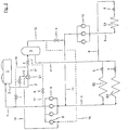
- FIG. 2 its composite refrigeration system in which a possible embodiment of the refrigeration cycle according to the invention is realized.
- a procedure is described in which as a refrigerant HFC (s), HFC (s) or CO 2 can be used.
- the compressed in the compressor unit 6 to a pressure between 10 and 120 bar refrigerant is fed via the pressure line 7 to the condenser or gas cooler 1 and condensed in this against external flow or deprived.
- the refrigerant is supplied to the refrigerant collector 3 via the lines 2, 2 'and 2 ", but according to the invention it is expanded in the intermediate expansion device a to an intermediate pressure of 5 to 40 bar and the collector 3 must be designed only to a lower pressure.
- the pressure to which the refrigerant is expanded in the mentioned intermediate relaxation device a is hereby preferably selected so that it is still below the lowest expected condensing pressure.
- the pressure line 7 with the sump 3. preferably with the gas space, connected or connectable.
- This connection between the pressure line 7 and the collecting container 3 can take place, for example, via a connecting line 17, in which an expansion valve h is arranged.
- the pressure line 7 is connected or connectable to the line or line sections 2 or 2 ', 2 "connecting the liquefier 1 and the collecting container 3.
- the collecting container 3 preferably the gas space, connected to the input of the compressor unit 6 or connectable.
- This connection between the collecting container 3 and the input of the compressor unit 6 can, for example, via a connecting line 12, as in the FIG. 2 shown, in the suction line 11 opens, done.
- the selected intermediate pressure can now be kept constant for all operating conditions.
- a scheme such that a constant difference value to the suction pressure exists. This ensures that the throttle steam fraction at the evaporators is comparatively small, with the result that the liquid and suction lines can be dimensioned correspondingly smaller.
- This also applies to the condensate line, since now no gaseous components have to flow through them back into the condenser 1.
- refrigerant is withdrawn from the collector 3 and the refrigerant consumers or their heat exchangers E2 and E3 supplied. This is preceded by a respective expansion valve b and c, in which the refrigerant flowing into the refrigeration consumer is expanded.
- the refrigerant evaporated in the refrigeration consumers E2 and E3 is then fed back to the compressor unit 6 via the suction line 5 or sucked out of the evaporators E2 and E3 by the latter.
- a portion of the withdrawn from the collector 3 via line 4 refrigerant is fed via line 8 one or more frozen consumers - represented by the heat exchanger E4-, which is also preceded by a relaxation valve d supplied.
- this partial refrigerant flow is fed to the compressor unit 10 via the suction line 9 and compressed thereinto to the inlet pressure of the compressor unit 6.
- the refrigerant partial stream thus compressed is then fed via line 11 to the inlet side of the compressor unit 6.
- a heat exchanger E1 can be connected upstream.
- the heat exchanger E1 is preferably connected on the input side to the output of the condenser 1 or connectable.
- the refrigerant stream to be expanded in the intermediate expansion device a is preferably cooled to such an extent that the throttled vapor portion of the expanded refrigerant is minimized.
- the resulting in the collector 3 throttle steam fractions can be sucked off via the line 12 and the dashed line 15 by means of the compressor 6 'at a higher pressure level.
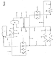
- FIG. 3 1 shows an embodiment of the refrigeration cycle according to the invention or of the method according to the invention for operating a refrigeration cycle, in which the refrigerant drawn off from the collecting container 3 via the line 4 is subjected to supercooling in the heat exchanger E5
- the subcooling takes place - in accordance with an advantageous embodiment of the invention - in heat exchange with the withdrawn from the reservoir 3 via line flash gas.
- Liquid lines such as those in the Figures 2 and 3 shown line 4, with a temperature level below the ambient temperature are exposed to heat radiation. This has the consequence that the refrigerant flowing inside the liquid line partially evaporates, thus resulting in the formation of undesirable vapor contents. To prevent this, refrigerant so far either by an expansion of a partial flow of the refrigerant and subsequent evaporation or by an internal heat transfer to a suction gas stream, which is thereby overheated, undercooled
- the temperature interval between the suction and liquid line or the circulating refrigerant therein may be too low to realize an internal heat transfer for the required supercooling of the refrigerant flowing in the liquid line.
- the procedure described thus has the additional advantage that the reliability of the compressor or compressor unit 6 is increased due to a safe overheating of the flash gas stream.
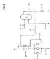
- FIG. 4 shows a further, Aunosti the refrigeration cycle of the invention or the inventive method for operating a Käftekrelsmoores.
- Aunosti the refrigeration cycle of the invention or the inventive method for operating a Käftekrelsmoores For the sake of clarity is in the FIG. 4 only a part of the in the FIG. 2 and 3 illustrated refrigeration circuit according to the invention shown
- the method according to the invention for operating a refrigeration cycle further develops that at least a partial flow of the flash gas withdrawn from the collecting container is at least temporarily overheated against at least a partial flow of the compressed refrigerant.
- FIG. 4 shows a possible embodiment of the method according to the invention, in which at least temporarily a partial flow of the withdrawn from the reservoir 3 via line 12 flash gas via line 16 to a heat exchanger E6 and superheated in this against the compressed in the compressor unit 6 refrigerant.
- the flash gas stream After passing through the heat exchanger / superheater E6, the flash gas stream is supplied via line 16 'to the inlet of the compressor 6' of the compressor unit 6.
Landscapes
- Engineering & Computer Science (AREA)
- Physics & Mathematics (AREA)
- Mechanical Engineering (AREA)
- Thermal Sciences (AREA)
- General Engineering & Computer Science (AREA)
- Chemical & Material Sciences (AREA)
- Chemical Kinetics & Catalysis (AREA)
- Devices That Are Associated With Refrigeration Equipment (AREA)
- Compression-Type Refrigeration Machines With Reversible Cycles (AREA)
- Air Conditioning Control Device (AREA)
- Air-Conditioning For Vehicles (AREA)
- Filling Or Discharging Of Gas Storage Vessels (AREA)
- Separation By Low-Temperature Treatments (AREA)
- Details Of Measuring And Other Instruments (AREA)
- Transmitters (AREA)
- Cold Air Circulating Systems And Constructional Details In Refrigerators (AREA)
Claims (16)
- Circuit frigorifique, présentant, dans le sens d'écoulement, un condenseur/refroidisseur de gaz (1), un dispositif de détente intermédiaire (a), un récipient collecteur (3), un dispositif de détente (b, c) installé en amont d'un évaporateur (E2, E3), un évaporateur (E2, E3) et un groupe compresseur (6), un autre groupe compresseur (10) ainsi qu'au moins un consommateur congélateur (E4) étant prévus avec une soupape de détente (d) installée en amont, un réfrigérant étant prélevé du récipient collecteur (3) lors du fonctionnement par l'intermédiaire d'un conduit d'aspiration (4), étant détendu dans le dispositif de détente (b, c) et étant amené aux évaporateurs (E2, E3) et puis, après l'évaporation dans les évaporateurs (E2, E3), étant amené au groupe compresseur (6) par l'intermédiaire d'un conduit d'aspiration (5) et un flux partiel de réfrigérant provenant du récipient collecteur (3) également étant amené à l'au moins un consommateur congélateur (E4) par l'intermédiaire du conduit d'aspiration (4) et d'un conduit (8) déviant de ce dernier et étant amené, après l'évaporation s'y déroulant, à l'autre groupe compresseur (10), le circuit frigorifique permettant un fonctionnement surcritique, l'autre groupe compresseur (10) compressant, lors du fonctionnement, le flux partiel de réfrigérant à la pression d'entrée du groupe compresseur (6) et l'amenant, par l'intermédiaire d'un conduit d'aspiration (11), qui débouche dans le conduit d'aspiration (5) avant le groupe compresseur (6), au côté d'entrée du groupe compresseur (6), et le compartiment à gaz du récipient collecteur (3) étant relié ou pouvant être relié à l'entrée du groupe compresseur (6), et une soupape de détente (e) étant prévue dans le conduit de liaison (11, 12) entre le compartiment à gaz du récipient colleteur (3) et l'entrée du groupe compresseur (6).
- Circuit frigorifique selon la revendication 1, un échangeur de chaleur (E1) étant installé en amont du récipient collecteur (3).
- Circuit frigorifique selon la revendication 2, l'échangeur de chaleur (E1) étant relié ou pouvant être relié côté entrée à la sortie du condenseur (1).
- Circuit frigorifique selon la revendication 2 ou 3, l'échangeur de chaleur (E1) étant relié ou pouvant être relié côté sortie à l'entrée d'un compresseur (6') du groupe compresseur (6).
- Circuit frigorifique selon l'une quelconque des revendications précédentes, le compartiment à gaz du récipient collecteur (3) étant relié ou pouvant être relié à l'entrée du groupe compresseur (6).
- Circuit frigorifique selon l'une quelconque des revendications précédentes, le compartiment à gaz du récipient collecteur (3) étant relié ou pouvant être relié à l'entrée d'un compresseur (6') du groupe compresseur (6).
- Circuit frigorifique selon l'une quelconque des revendications précédentes, le conduit de pression (7) étant relié ou pouvant être relié au récipient collecteur (3), de préférence au compartiment à gaz de ce dernier, ou au conduit (2, 2', 2") reliant le condenseur/refroidisseur de gaz (1) et le récipient collecteur (3).
- Circuit frigorifique selon l'une quelconque des revendications précédentes, un échangeur de chaleur/ sous-refroidisseur (E5) étant disposé entre le récipient collecteur (3) et le dispositif de détente (c, b, d) installé en amont d'un évaporateur.
- Circuit frigorifique selon l'une quelconque des revendications précédentes, l'échangeur de chaleur/sous-refroidisseur (E5) étant relié ou pouvant être relié côté entrée au compartiment à gaz du récipient collecteur (3).
- Procédé servant à faire fonctionner un circuit frigorifique selon l'une quelconque des revendications précédentes, présentant les étapes suivantes consistant à :détendre le réfrigérant dans le dispositif de détente intermédiaire (a) disposé entre le condenseur/refroidisseur de gaz (1) et le récipient collecteur (3) à une pression intermédiaire allant de 5 à 40 bar,prélever le réfrigérant du récipient collecteur (3) et l'amener aux évaporateurs (E2, E3) par l'intermédiaire d'un conduit d'aspiration (4),détendre le réfrigérant dans les soupapes de détente (b, c) installées en amont des évaporateurs (E2, E3),évaporer le réfrigérant dans les évaporateurs (E2, E3) et amener le réfrigérant évaporé au groupe compresseur (6) par l'intermédiaire d'un conduit d'aspiration (5),amener un flux partiel de réfrigérant provenant du récipient collecteur (3) à l'au moins un consommateur congélateur (E4) par l'intermédiaire du conduit d'aspiration (4) et d'un conduit (8) déviant de ce dernier,évaporer le flux partiel de réfrigérant dans l'au moins un consommateur congélateur (E4),amener le flux partiel de réfrigérant évaporé à l'autre groupe compresseur (10);un fonctionnement supercritique devenant possible,l'autre groupe compresseur (10) compressant le flux partiel de réfrigérant à la pression d'entrée du groupe compresseur (6) et l'amenant, par l'intermédiaire d'un conduit d'aspiration (11), qui débouche dans le conduit d'aspiration (5) avant le groupe compresseur (6); au côté d'entrée du groupe compresseur (6), et la pression intermédiaire étant régulée à une valeur constante au moyen d'une soupape de détente (e) prévue dans le conduit de liaison (11, 12) entre le compartiment à gaz du récipient collecteur (3) et l'entrée du groupe compresseur (6).
- Procédé selon la revendication 10, le réfrigérant (2) étant refroidi avant sa détente intermédiaire (a).
- Procédé selon la revendication 11, le refroidissement (E1) du réfrigérant (2) se déroulant contrairement à un flux partiel du réfrigérant (13).
- Procédé selon l'une quelconque des revendications 10 à 12, le réfrigérant (4) prélevé du récipient collecteur (3) étant sous-refroidi.
- Procédé selon la revendication 13, le sous-refroidissement (E5) du réfrigérant (4) prélevé du récipient collecteur (3) se déroulant contrairement au gaz de vaporisation éclair (12) prélevé du récipient collecteur (3).
- Procédé selon l'une quelconque des revendications 10 à 14, au moins un flux partiel du gaz de vaporisation éclair (12) prélevé du récipient collecteur (3) étant surchauffé au moins de manière temporaire contrairement au réfrigérant (7) condensé.
- Procédé selon l'une quelconque des revendications 10 à 15, la pression intermédiaire étant régulée à une valeur constante au moyen au moins d'une soupape (e, h, j) et/ou à une différence constante par rapport à la pression d'aspiration.
Applications Claiming Priority (2)
| Application Number | Priority Date | Filing Date | Title |
|---|---|---|---|
| DE102004038640A DE102004038640A1 (de) | 2004-08-09 | 2004-08-09 | Kältekreislauf und Verfahen zum Betreiben eines Kältekreislaufes |
| EP05775838A EP1789732B1 (fr) | 2004-08-09 | 2005-07-29 | Circuit frigorifique et procede de fonctionnement d'un circuit frigorifique |
Related Parent Applications (1)
| Application Number | Title | Priority Date | Filing Date |
|---|---|---|---|
| EP05775838A Division EP1789732B1 (fr) | 2004-08-09 | 2005-07-29 | Circuit frigorifique et procede de fonctionnement d'un circuit frigorifique |
Publications (4)
| Publication Number | Publication Date |
|---|---|
| EP1895246A2 EP1895246A2 (fr) | 2008-03-05 |
| EP1895246A3 EP1895246A3 (fr) | 2009-02-11 |
| EP1895246B1 EP1895246B1 (fr) | 2016-11-23 |
| EP1895246B3 true EP1895246B3 (fr) | 2018-05-02 |
Family
ID=34961069
Family Applications (6)
| Application Number | Title | Priority Date | Filing Date |
|---|---|---|---|
| EP05715407.2A Active EP1782001B1 (fr) | 2004-08-09 | 2005-02-18 | Vidange de vapeur instantanée du réservoir d'un circuit refrigérant |
| EP05723393A Not-in-force EP1794510B1 (fr) | 2004-08-09 | 2005-02-18 | Circuit de réfrigération à co2 avec sous-refroidissement de l'agent réfrigérant liquide contre la vapeur instantanée de la bouteille accumulatrice et méthode pour exploiter celui-ci |
| EP10181303.8A Active EP2264385B1 (fr) | 2004-08-09 | 2005-07-29 | Cycle frigorifique et procédé d'operation d'un cycle frigorifique |
| EP05775838A Active EP1789732B1 (fr) | 2004-08-09 | 2005-07-29 | Circuit frigorifique et procede de fonctionnement d'un circuit frigorifique |
| EP10167202.0A Active EP2244040B1 (fr) | 2004-08-09 | 2005-07-29 | Vidange de vapeur instantanée du réservoir d'un circuit refrigérant |
| EP07020311.2A Active EP1895246B3 (fr) | 2004-08-09 | 2005-07-29 | Circuit frigorifique et procédé de fonctionnement d'un circuit frigorifique |
Family Applications Before (5)
| Application Number | Title | Priority Date | Filing Date |
|---|---|---|---|
| EP05715407.2A Active EP1782001B1 (fr) | 2004-08-09 | 2005-02-18 | Vidange de vapeur instantanée du réservoir d'un circuit refrigérant |
| EP05723393A Not-in-force EP1794510B1 (fr) | 2004-08-09 | 2005-02-18 | Circuit de réfrigération à co2 avec sous-refroidissement de l'agent réfrigérant liquide contre la vapeur instantanée de la bouteille accumulatrice et méthode pour exploiter celui-ci |
| EP10181303.8A Active EP2264385B1 (fr) | 2004-08-09 | 2005-07-29 | Cycle frigorifique et procédé d'operation d'un cycle frigorifique |
| EP05775838A Active EP1789732B1 (fr) | 2004-08-09 | 2005-07-29 | Circuit frigorifique et procede de fonctionnement d'un circuit frigorifique |
| EP10167202.0A Active EP2244040B1 (fr) | 2004-08-09 | 2005-07-29 | Vidange de vapeur instantanée du réservoir d'un circuit refrigérant |
Country Status (11)
| Country | Link |
|---|---|
| US (2) | US7644593B2 (fr) |
| EP (6) | EP1782001B1 (fr) |
| KR (2) | KR20070050046A (fr) |
| CN (3) | CN100507402C (fr) |
| AT (1) | ATE544992T1 (fr) |
| AU (2) | AU2005278162A1 (fr) |
| DK (4) | DK1794510T3 (fr) |
| HK (2) | HK1101199A1 (fr) |
| NO (1) | NO343330B1 (fr) |
| RU (1) | RU2362096C2 (fr) |
| WO (1) | WO2006022829A1 (fr) |
Families Citing this family (56)
| Publication number | Priority date | Publication date | Assignee | Title |
|---|---|---|---|---|
| DK1782001T3 (en) * | 2004-08-09 | 2017-03-13 | Carrier Corp | FLASH GAS REMOVAL FROM A RECEIVER IN A COOLING CIRCUIT |
| US8322150B2 (en) | 2006-03-27 | 2012-12-04 | Carrier Corporation | Refrigerating system with parallel staged economizer circuits discharging to interstage pressures of a main compressor |
| EP2008036B1 (fr) * | 2006-03-27 | 2015-12-02 | Carrier Corporation | Système réfrigérant avec circuits économiseurs étagés parallèles employant une compression multi-étage |
| DK2005079T3 (en) * | 2006-03-27 | 2017-02-06 | Carrier Corp | COOLING SYSTEM WITH PARALLEL STEP ECONOMIZER CIRCUIT AND ONE OR 2-STEP HEAD COMPRESSOR |
| CN101460789B (zh) * | 2006-06-01 | 2011-01-26 | 开利公司 | 适于制冷系统的多级压缩机单元 |
| US8196421B2 (en) * | 2006-06-01 | 2012-06-12 | Carrier Corporation | System and method for controlled expansion valve adjustment |
| WO2008019689A2 (fr) * | 2006-08-18 | 2008-02-21 | Knudsen Køling A/S | Système de réfrigération transcritique doté d'un surpresseur |
| DE102006050232B9 (de) * | 2006-10-17 | 2008-09-18 | Bitzer Kühlmaschinenbau Gmbh | Kälteanlage |
| US20080289350A1 (en) * | 2006-11-13 | 2008-11-27 | Hussmann Corporation | Two stage transcritical refrigeration system |
| CN101413738A (zh) | 2007-10-17 | 2009-04-22 | 开利公司 | 一种中低温集成式冷藏/冷冻系统 |
| JP2009139037A (ja) * | 2007-12-07 | 2009-06-25 | Mitsubishi Heavy Ind Ltd | 冷媒回路 |
| DK2318782T3 (en) * | 2008-07-07 | 2019-04-23 | Carrier Corp | COOLING CIRCUIT |
| WO2010003555A1 (fr) * | 2008-07-07 | 2010-01-14 | Carrier Corporation | Circuit de réfrigération |
| US8631666B2 (en) * | 2008-08-07 | 2014-01-21 | Hill Phoenix, Inc. | Modular CO2 refrigeration system |
| WO2010045743A1 (fr) | 2008-10-23 | 2010-04-29 | Dube Serge | Système frigorifique par co2 |
| ITTV20080140A1 (it) * | 2008-11-04 | 2010-05-05 | Enex Srl | Sistema frigorifero con compressore alternativo ed economizzatore. |
| US20100281914A1 (en) * | 2009-05-07 | 2010-11-11 | Dew Point Control, Llc | Chilled water skid for natural gas processing |
| BR112012010481A2 (pt) * | 2009-11-03 | 2016-03-15 | Du Pont | sistema de refrigeração em cascata e metodo de troca de calor entre pelo menos dois ciclos de refrigeração |
| JP5595025B2 (ja) * | 2009-12-10 | 2014-09-24 | 三菱重工業株式会社 | 空気調和機および空気調和機の冷媒量検出方法 |
| CA2724255C (fr) * | 2010-09-28 | 2011-09-13 | Serge Dube | Systeme de refrigeration au co2 pour surfaces de sports sur glace |
| CN102589217B (zh) * | 2011-01-10 | 2016-02-03 | 珠海格力电器股份有限公司 | 冷媒量控制装置和方法及具有该控制装置的空调机组 |
| WO2012095186A1 (fr) * | 2011-01-14 | 2012-07-19 | Carrier Corporation | Système de réfrigération et procédé de fonctionnement d'un système de réfrigération |
| DK177329B1 (en) | 2011-06-16 | 2013-01-14 | Advansor As | Refrigeration system |
| US8863494B2 (en) | 2011-10-06 | 2014-10-21 | Hamilton Sundstrand Space Systems International, Inc. | Turbine outlet frozen gas capture apparatus and method |
| CA2807643C (fr) * | 2012-02-23 | 2017-01-03 | Systemes Lmp Inc. | Sous-refroidissement mecanique de systemes de refrigeration r-744 transcritiques avec recuperation de chaleur et pression de tete flottante de pompe a chaleur |
| RU2614417C2 (ru) * | 2012-04-27 | 2017-03-28 | Кэрриер Корпорейшн | Система охлаждения |
| WO2013174379A1 (fr) | 2012-05-22 | 2013-11-28 | Danfoss A/S | Procédé pour actionner une machine frigorifique à compression dans un climat chaud |
| WO2014068967A1 (fr) * | 2012-10-31 | 2014-05-08 | パナソニック株式会社 | Dispositif de réfrigération |
| US9194615B2 (en) | 2013-04-05 | 2015-11-24 | Marc-Andre Lesmerises | CO2 cooling system and method for operating same |
| BR112015027590B1 (pt) | 2013-05-03 | 2022-05-31 | Hill Phoenix, Inc | Sistema e método para o controle da pressão de um sistema de refrigeração de co2 |
| JP6091399B2 (ja) * | 2013-10-17 | 2017-03-08 | 三菱電機株式会社 | 空気調和装置 |
| EP2889558B1 (fr) | 2013-12-30 | 2019-05-08 | Rolls-Royce Corporation | Système de refroidissement avec machine à expansion et éjecteur |
| US9739200B2 (en) | 2013-12-30 | 2017-08-22 | Rolls-Royce Corporation | Cooling systems for high mach applications |
| US9696074B2 (en) * | 2014-01-03 | 2017-07-04 | Woodward, Inc. | Controlling refrigeration compression systems |
| US9726411B2 (en) * | 2015-03-04 | 2017-08-08 | Heatcraft Refrigeration Products L.L.C. | Modulated oversized compressors configuration for flash gas bypass in a carbon dioxide refrigeration system |
| CA2928553C (fr) | 2015-04-29 | 2023-09-26 | Marc-Andre Lesmerises | Appareil de refroidissement de co2 et methode d'exploitation dudit appareil |
| US10543737B2 (en) | 2015-12-28 | 2020-01-28 | Thermo King Corporation | Cascade heat transfer system |
| US11125483B2 (en) | 2016-06-21 | 2021-09-21 | Hill Phoenix, Inc. | Refrigeration system with condenser temperature differential setpoint control |
| DE102016116028B4 (de) | 2016-07-18 | 2019-12-12 | imbut GmbH | Verfahren zum Fixieren von elektronischen Bauelementen auf einem flexiblen, insbesondere textilen Flächengebilde |
| US10352604B2 (en) * | 2016-12-06 | 2019-07-16 | Heatcraft Refrigeration Products Llc | System for controlling a refrigeration system with a parallel compressor |
| CN106766297B (zh) * | 2016-12-22 | 2019-08-16 | 广州协义自动化科技有限公司 | 一种能快速恢复平衡压力的超低温水汽捕集泵系统 |
| KR101891993B1 (ko) * | 2017-01-19 | 2018-08-28 | 주식회사 신진에너텍 | 급냉실 냉동실 냉장실의 3단계 냉각 시스템 |
| US10830499B2 (en) * | 2017-03-21 | 2020-11-10 | Heatcraft Refrigeration Products Llc | Transcritical system with enhanced subcooling for high ambient temperature |
| US10648701B2 (en) | 2018-02-06 | 2020-05-12 | Thermo Fisher Scientific (Asheville) Llc | Refrigeration systems and methods using water-cooled condenser and additional water cooling |
| US11022382B2 (en) | 2018-03-08 | 2021-06-01 | Johnson Controls Technology Company | System and method for heat exchanger of an HVAC and R system |
| US10907869B2 (en) | 2018-05-24 | 2021-02-02 | Honeywell International Inc. | Integrated vapor cycle and pumped two-phase cooling system with latent thermal storage of refrigerants for transient thermal management |
| US11796227B2 (en) | 2018-05-24 | 2023-10-24 | Hill Phoenix, Inc. | Refrigeration system with oil control system |
| US11397032B2 (en) | 2018-06-05 | 2022-07-26 | Hill Phoenix, Inc. | CO2 refrigeration system with magnetic refrigeration system cooling |
| US11187445B2 (en) * | 2018-07-02 | 2021-11-30 | Heatcraft Refrigeration Products Llc | Cooling system |
| US10663201B2 (en) | 2018-10-23 | 2020-05-26 | Hill Phoenix, Inc. | CO2 refrigeration system with supercritical subcooling control |
| CN110332635B (zh) * | 2019-07-09 | 2024-03-19 | 珠海格力节能环保制冷技术研究中心有限公司 | 一种双级压缩多补气制冷热泵系统、控制方法和空调器 |
| CN110319613B (zh) * | 2019-07-22 | 2023-05-26 | 北京市京科伦冷冻设备有限公司 | 单级二氧化碳制冷系统 |
| CN114375382B (zh) * | 2019-09-18 | 2023-10-24 | 株式会社日立产机系统 | 热回收装置 |
| US11686513B2 (en) | 2021-02-23 | 2023-06-27 | Johnson Controls Tyco IP Holdings LLP | Flash gas bypass systems and methods for an HVAC system |
| CN114459179B (zh) * | 2021-12-27 | 2023-05-12 | 华北理工大学 | 人工冰场二氧化碳直接蒸发式制冰系统及其使用方法 |
| CN115077114A (zh) * | 2022-06-08 | 2022-09-20 | 松下冷机系统(大连)有限公司 | Co2跨临界船用碳捕集制冷机组 |
Family Cites Families (50)
| Publication number | Priority date | Publication date | Assignee | Title |
|---|---|---|---|---|
| US933682A (en) * | 1908-07-03 | 1909-09-07 | Gardner Tufts Voorhees | Multiple-effect receiver. |
| US1860447A (en) * | 1928-07-21 | 1932-05-31 | York Ice Machinery Corp | Refrigeration |
| US2585908A (en) * | 1944-12-19 | 1952-02-19 | Electrolux Ab | Multiple temperature refrigeration system |
| US2680956A (en) * | 1951-12-19 | 1954-06-15 | Haskris Co | Plural stage refrigeration system |
| US3150498A (en) * | 1962-03-08 | 1964-09-29 | Ray Winther Company | Method and apparatus for defrosting refrigeration systems |
| US4151724A (en) * | 1977-06-13 | 1979-05-01 | Frick Company | Pressurized refrigerant feed with recirculation for compound compression refrigeration systems |
| JPS5523859A (en) * | 1978-08-08 | 1980-02-20 | Tokyo Shibaura Electric Co | Pluralltemperature refrigeration cycle |
| FR2513747A1 (fr) * | 1981-09-25 | 1983-04-01 | Satam Brandt Froid | Installation frigorifique a multimotocompresseurs |
| US4430866A (en) * | 1982-09-07 | 1984-02-14 | Emhart Industries, Inc. | Pressure control means for refrigeration systems of the energy conservation type |
| JPS60262A (ja) * | 1983-06-17 | 1985-01-05 | 株式会社日立製作所 | 冷凍サイクル |
| US4947655A (en) * | 1984-01-11 | 1990-08-14 | Copeland Corporation | Refrigeration system |
| US4599873A (en) * | 1984-01-31 | 1986-07-15 | Hyde Robert E | Apparatus for maximizing refrigeration capacity |
| JPS6164526A (ja) * | 1984-09-06 | 1986-04-02 | Nippon Denso Co Ltd | 車両用冷房冷凍装置 |
| DE3440253A1 (de) | 1984-11-03 | 1986-05-15 | Bitzer Kühlmaschinenbau GmbH & Co KG, 7032 Sindelfingen | Kuehlvorrichtung |
| US4621505A (en) * | 1985-08-01 | 1986-11-11 | Hussmann Corporation | Flow-through surge receiver |
| US4742694A (en) * | 1987-04-17 | 1988-05-10 | Nippondenso Co., Ltd. | Refrigerant apparatus |
| FR2620205A1 (fr) * | 1987-09-04 | 1989-03-10 | Zimmern Bernard | Compresseur hermetique pour refrigeration avec moteur refroidi par gaz d'economiseur |
| US4779427A (en) * | 1988-01-22 | 1988-10-25 | E. Squared Incorporated | Heat actuated heat pump |
| US4831835A (en) * | 1988-04-21 | 1989-05-23 | Tyler Refrigeration Corporation | Refrigeration system |
| JPH01318860A (ja) * | 1988-06-20 | 1989-12-25 | Toshiba Corp | 冷凍サイクル装置 |
| US5042268A (en) | 1989-11-22 | 1991-08-27 | Labrecque James C | Refrigeration |
| US5042262A (en) * | 1990-05-08 | 1991-08-27 | Liquid Carbonic Corporation | Food freezer |
| US5103650A (en) * | 1991-03-29 | 1992-04-14 | General Electric Company | Refrigeration systems with multiple evaporators |
| GB2258298B (en) * | 1991-07-31 | 1995-05-17 | Star Refrigeration | Cooling method and apparatus |
| JPH0545007A (ja) * | 1991-08-09 | 1993-02-23 | Nippondenso Co Ltd | 冷凍サイクル |
| US5174123A (en) | 1991-08-23 | 1992-12-29 | Thermo King Corporation | Methods and apparatus for operating a refrigeration system |
| US5191776A (en) * | 1991-11-04 | 1993-03-09 | General Electric Company | Household refrigerator with improved circuit |
| JPH06159826A (ja) * | 1992-11-24 | 1994-06-07 | Hitachi Ltd | 多段圧縮冷凍装置 |
| DE4309137A1 (de) * | 1993-02-02 | 1994-08-04 | Otfried Dipl Ing Knappe | Verfahren für einen Kälteprozeß und Vorrichtung zur Durchführung desselben |
| EP0658730B1 (fr) * | 1993-12-14 | 1998-10-21 | Carrier Corporation | Commande d'économiseur pour des systèmes à compresseur à deux étages |
| JPH07225059A (ja) * | 1994-02-14 | 1995-08-22 | Teruo Kinoshita | 多機能冷凍サイクルシステム |
| JPH085163A (ja) | 1994-06-16 | 1996-01-12 | Mitsubishi Heavy Ind Ltd | 冷凍サイクル装置 |
| US5522233A (en) * | 1994-12-21 | 1996-06-04 | Carrier Corporation | Makeup oil system for first stage oil separation in booster system |
| DE19522884A1 (de) | 1995-06-23 | 1997-01-02 | Inst Luft Kaeltetech Gem Gmbh | Verfahren zum Betrieb einer Kompressionskälteanlage |
| FR2738331B1 (fr) * | 1995-09-01 | 1997-11-21 | Profroid Ind Sa | Dispositif d'optimisation energetique d'un ensemble de refrigeration a compression et a detente directe |
| NO970066D0 (no) * | 1997-01-08 | 1997-01-08 | Norild As | Kuldeanlegg med lukket sirkulasjonskrets |
| JPH1163694A (ja) * | 1997-08-21 | 1999-03-05 | Zexel Corp | 冷却サイクル |
| JP2000154941A (ja) * | 1998-11-19 | 2000-06-06 | Matsushita Electric Ind Co Ltd | 冷凍装置 |
| WO2000049346A1 (fr) | 1999-02-17 | 2000-08-24 | Yanmar Diesel Engine Co., Ltd. | Circuit de refroidissement a refrigerant |
| EP1046869B1 (fr) | 1999-04-20 | 2005-02-02 | Sanden Corporation | Système de réfrigération et d'air conditionné |
| DE19920726A1 (de) * | 1999-05-05 | 2000-11-09 | Linde Ag | Kälteanlage |
| US6276148B1 (en) * | 2000-02-16 | 2001-08-21 | David N. Shaw | Boosted air source heat pump |
| AU2001293280A1 (en) * | 2000-09-15 | 2002-03-26 | Mile High Equipment Company | Quiet ice making apparatus |
| JP2002156161A (ja) * | 2000-11-16 | 2002-05-31 | Mitsubishi Heavy Ind Ltd | 空気調和装置 |
| US6470693B1 (en) * | 2001-07-11 | 2002-10-29 | Ingersoll-Rand Company | Compressed air refrigeration system |
| JP3603848B2 (ja) * | 2001-10-23 | 2004-12-22 | ダイキン工業株式会社 | 冷凍装置 |
| US6981377B2 (en) * | 2002-02-25 | 2006-01-03 | Outfitter Energy Inc | System and method for generation of electricity and power from waste heat and solar sources |
| JP2003254661A (ja) * | 2002-02-27 | 2003-09-10 | Toshiba Corp | 冷蔵庫 |
| US6694763B2 (en) * | 2002-05-30 | 2004-02-24 | Praxair Technology, Inc. | Method for operating a transcritical refrigeration system |
| DE10258524A1 (de) * | 2002-12-14 | 2004-07-15 | Volkswagen Ag | Kältemittelkreislauf für eine Kfz-Klimaanlage |
-
2005
- 2005-02-18 AU AU2005278162A patent/AU2005278162A1/en not_active Abandoned
- 2005-02-18 EP EP05715407.2A patent/EP1782001B1/fr active Active
- 2005-02-18 US US11/659,925 patent/US7644593B2/en not_active Expired - Fee Related
- 2005-02-18 EP EP05723393A patent/EP1794510B1/fr not_active Not-in-force
- 2005-02-18 AT AT05723393T patent/ATE544992T1/de active
- 2005-02-18 KR KR1020077003139A patent/KR20070050046A/ko not_active Application Discontinuation
- 2005-02-18 WO PCT/US2005/005413 patent/WO2006022829A1/fr active Application Filing
- 2005-02-18 RU RU2007107807/06A patent/RU2362096C2/ru not_active IP Right Cessation
- 2005-02-18 CN CNB2005800267473A patent/CN100507402C/zh not_active Expired - Fee Related
- 2005-02-18 DK DK05723393.4T patent/DK1794510T3/da active
- 2005-07-29 EP EP10181303.8A patent/EP2264385B1/fr active Active
- 2005-07-29 CN CN200580026836A patent/CN100582603C/zh active Active
- 2005-07-29 EP EP05775838A patent/EP1789732B1/fr active Active
- 2005-07-29 EP EP10167202.0A patent/EP2244040B1/fr active Active
- 2005-07-29 DK DK10181303.8T patent/DK2264385T3/en active
- 2005-07-29 KR KR1020077003141A patent/KR20070046847A/ko not_active Application Discontinuation
- 2005-07-29 AU AU2005270472A patent/AU2005270472B2/en not_active Ceased
- 2005-07-29 EP EP07020311.2A patent/EP1895246B3/fr active Active
- 2005-07-29 US US11/659,926 patent/US8113008B2/en active Active
- 2005-07-29 DK DK10167202T patent/DK2244040T3/da active
- 2005-07-29 CN CN2009102463806A patent/CN101713596B/zh active Active
- 2005-07-29 DK DK07020311.2T patent/DK1895246T6/da active
-
2007
- 2007-03-06 NO NO20071229A patent/NO343330B1/no unknown
- 2007-08-23 HK HK07109213.5A patent/HK1101199A1/xx not_active IP Right Cessation
-
2010
- 2010-11-04 HK HK10110346.8A patent/HK1144011A1/xx not_active IP Right Cessation
Also Published As
Similar Documents
| Publication | Publication Date | Title |
|---|---|---|
| EP1895246B3 (fr) | Circuit frigorifique et procédé de fonctionnement d'un circuit frigorifique | |
| WO2006015741A1 (fr) | Circuit frigorifique et procede de fonctionnement d'un circuit frigorifique | |
| DE69930732T2 (de) | Kälteanlage | |
| DE112015004059T5 (de) | Zentrifugalkühler | |
| DE102019201427A1 (de) | Verfahren zum Betreiben eines Kältemittelkreislaufs einer Kälteanlage eines Fahrzeugs | |
| EP3099985B1 (fr) | Système de réfrigération | |
| EP1050726B1 (fr) | Système frigorifique | |
| DE3440253A1 (de) | Kuehlvorrichtung | |
| DE102011012644A1 (de) | Kälteanlage | |
| DE10001470A1 (de) | Verfahren zum Betreiben einer Klimatisierungseinrichtung für Fahrzeuge und Ausführung des erforderlichen Abscheidesammlers | |
| EP1050723B1 (fr) | Système frigorifique et procédé de fonctionnement d'un système frigorifique | |
| EP1498673B1 (fr) | Système de dégivrage par gaz chaud pour installations de réfrigération | |
| DE19533755C2 (de) | Vorrichtung und Verfahren zur Erzeugung von Wärme und Kälte | |
| DE19832682C2 (de) | Abtaueinrichtung für einen Verdampfer einer Wärmepumpe oder eines Klimageräts | |
| DE102019111309A1 (de) | Ejektor-basiertes Kühlungssystem und Kühlungsverfahren | |
| EP1714094A1 (fr) | Installation frigorifique et procede pour faire fonctionner une installation frigorifique | |
| DE3322474A1 (de) | Verfahren zum betreiben eines kaeltemittelkreislaufs und kaeltemittelkreislauf zur durchfuehrung des verfahrens | |
| EP1050724A2 (fr) | Système frigorifique | |
| DE19826291A1 (de) | Verfahren zum Betreiben einer Pumpe zur Förderung siedender Kältemittel oder Kälteträger | |
| DE102021125108A1 (de) | Expansions-Kompressionsmaschine für Kältekreisläufe | |
| WO2005075904A1 (fr) | Meuble frigorifique, y compris congelateur, a mode de circulation naturelle | |
| WO2011097748A2 (fr) | Pompe à chaleur | |
| DE102008013373B4 (de) | Kaskadenkühlvorrichtung und Kaskadenkühlverfahren | |
| DE10131473A1 (de) | Kälteanlage und Verfahren zum Betreiben einer Kälteanlage |
Legal Events
| Date | Code | Title | Description |
|---|---|---|---|
| PUAI | Public reference made under article 153(3) epc to a published international application that has entered the european phase |
Free format text: ORIGINAL CODE: 0009012 |
|
| AC | Divisional application: reference to earlier application |
Ref document number: 1789732 Country of ref document: EP Kind code of ref document: P |
|
| AK | Designated contracting states |
Kind code of ref document: A2 Designated state(s): AT BE BG CH CY CZ DE DK EE ES FI FR GB GR HU IE IS IT LI LT LU LV MC NL PL PT RO SE SI SK TR |
|
| PUAL | Search report despatched |
Free format text: ORIGINAL CODE: 0009013 |
|
| AK | Designated contracting states |
Kind code of ref document: A3 Designated state(s): AT BE BG CH CY CZ DE DK EE ES FI FR GB GR HU IE IS IT LI LT LU LV MC NL PL PT RO SE SI SK TR |
|
| RIC1 | Information provided on ipc code assigned before grant |
Ipc: F25B 41/04 20060101ALI20090108BHEP Ipc: F25B 1/10 20060101ALI20090108BHEP Ipc: F25B 9/00 20060101AFI20080129BHEP |
|
| 17P | Request for examination filed |
Effective date: 20090807 |
|
| AKX | Designation fees paid |
Designated state(s): AT BE BG CH CY CZ DE DK EE ES FI FR GB GR HU IE IS IT LI LT LU LV MC NL PL PT RO SE SI SK TR |
|
| 17Q | First examination report despatched |
Effective date: 20091001 |
|
| RAP1 | Party data changed (applicant data changed or rights of an application transferred) |
Owner name: CARRIER CORPORATION |
|
| GRAP | Despatch of communication of intention to grant a patent |
Free format text: ORIGINAL CODE: EPIDOSNIGR1 |
|
| INTG | Intention to grant announced |
Effective date: 20160718 |
|
| GRAS | Grant fee paid |
Free format text: ORIGINAL CODE: EPIDOSNIGR3 |
|
| GRAA | (expected) grant |
Free format text: ORIGINAL CODE: 0009210 |
|
| AC | Divisional application: reference to earlier application |
Ref document number: 1789732 Country of ref document: EP Kind code of ref document: P |
|
| AK | Designated contracting states |
Kind code of ref document: B1 Designated state(s): AT BE BG CH CY CZ DE DK EE ES FI FR GB GR HU IE IS IT LI LT LU LV MC NL PL PT RO SE SI SK TR |
|
| REG | Reference to a national code |
Ref country code: GB Ref legal event code: FG4D Free format text: NOT ENGLISH |
|
| REG | Reference to a national code |
Ref country code: CH Ref legal event code: EP |
|
| REG | Reference to a national code |
Ref country code: IE Ref legal event code: FG4D Free format text: LANGUAGE OF EP DOCUMENT: GERMAN |
|
| REG | Reference to a national code |
Ref country code: AT Ref legal event code: REF Ref document number: 848290 Country of ref document: AT Kind code of ref document: T Effective date: 20161215 |
|
| REG | Reference to a national code |
Ref country code: DE Ref legal event code: R055 Ref document number: 502005015435 Country of ref document: DE |
|
| PLCP | Request for limitation filed |
Free format text: ORIGINAL CODE: EPIDOSNLIM1 |
|
| REG | Reference to a national code |
Ref country code: DE Ref legal event code: R096 Ref document number: 502005015435 Country of ref document: DE |
|
| PLCQ | Request for limitation of patent found admissible |
Free format text: ORIGINAL CODE: 0009231 |
|
| PG25 | Lapsed in a contracting state [announced via postgrant information from national office to epo] |
Ref country code: LV Free format text: LAPSE BECAUSE OF FAILURE TO SUBMIT A TRANSLATION OF THE DESCRIPTION OR TO PAY THE FEE WITHIN THE PRESCRIBED TIME-LIMIT Effective date: 20161123 |
|
| PLBV | Information modified related to decision on request for limitation of patent |
Free format text: ORIGINAL CODE: 0009299LIMP |
|
| REG | Reference to a national code |
Ref country code: DK Ref legal event code: T3 Effective date: 20170228 |
|
| LIM1 | Request for limitation found admissible |
Free format text: SEQUENCE NO: 1; FILED DURING OPPOSITION PERIOD Filing date: 20161216 Effective date: 20161216 |
|
| REG | Reference to a national code |
Ref country code: SE Ref legal event code: TRGR |
|
| REG | Reference to a national code |
Ref country code: LT Ref legal event code: MG4D |
|
| REG | Reference to a national code |
Ref country code: NL Ref legal event code: MP Effective date: 20161123 |
|
| PG25 | Lapsed in a contracting state [announced via postgrant information from national office to epo] |
Ref country code: GR Free format text: LAPSE BECAUSE OF FAILURE TO SUBMIT A TRANSLATION OF THE DESCRIPTION OR TO PAY THE FEE WITHIN THE PRESCRIBED TIME-LIMIT Effective date: 20170224 Ref country code: LT Free format text: LAPSE BECAUSE OF FAILURE TO SUBMIT A TRANSLATION OF THE DESCRIPTION OR TO PAY THE FEE WITHIN THE PRESCRIBED TIME-LIMIT Effective date: 20161123 Ref country code: NL Free format text: LAPSE BECAUSE OF FAILURE TO SUBMIT A TRANSLATION OF THE DESCRIPTION OR TO PAY THE FEE WITHIN THE PRESCRIBED TIME-LIMIT Effective date: 20161123 |
|
| PG25 | Lapsed in a contracting state [announced via postgrant information from national office to epo] |
Ref country code: FI Free format text: LAPSE BECAUSE OF FAILURE TO SUBMIT A TRANSLATION OF THE DESCRIPTION OR TO PAY THE FEE WITHIN THE PRESCRIBED TIME-LIMIT Effective date: 20161123 Ref country code: PL Free format text: LAPSE BECAUSE OF FAILURE TO SUBMIT A TRANSLATION OF THE DESCRIPTION OR TO PAY THE FEE WITHIN THE PRESCRIBED TIME-LIMIT Effective date: 20161123 Ref country code: PT Free format text: LAPSE BECAUSE OF FAILURE TO SUBMIT A TRANSLATION OF THE DESCRIPTION OR TO PAY THE FEE WITHIN THE PRESCRIBED TIME-LIMIT Effective date: 20170323 Ref country code: ES Free format text: LAPSE BECAUSE OF FAILURE TO SUBMIT A TRANSLATION OF THE DESCRIPTION OR TO PAY THE FEE WITHIN THE PRESCRIBED TIME-LIMIT Effective date: 20161123 |
|
| PLBV | Information modified related to decision on request for limitation of patent |
Free format text: ORIGINAL CODE: 0009299LIMP |
|
| PLCR | Communication despatched that request for limitation of patent was allowed |
Free format text: ORIGINAL CODE: 0009245 |
|
| REG | Reference to a national code |
Ref country code: DE Ref legal event code: R056 Ref document number: 502005015435 Country of ref document: DE |
|
| REG | Reference to a national code |
Ref country code: DE Ref legal event code: R082 Ref document number: 502005015435 Country of ref document: DE Representative=s name: SCHMITT-NILSON SCHRAUD WAIBEL WOHLFROM PATENTA, DE |
|
| LIM1 | Request for limitation found admissible |
Free format text: SEQUENCE NO: 1; FILED DURING OPPOSITION PERIOD; CHANGE OF DECISION ON REQUEST FOR LIMITATION OF PATENT Filing date: 20161216 Effective date: 20161216 |
|
| REG | Reference to a national code |
Ref country code: FR Ref legal event code: PLFP Year of fee payment: 13 |
|
| PG25 | Lapsed in a contracting state [announced via postgrant information from national office to epo] |
Ref country code: CZ Free format text: LAPSE BECAUSE OF FAILURE TO SUBMIT A TRANSLATION OF THE DESCRIPTION OR TO PAY THE FEE WITHIN THE PRESCRIBED TIME-LIMIT Effective date: 20161123 Ref country code: EE Free format text: LAPSE BECAUSE OF FAILURE TO SUBMIT A TRANSLATION OF THE DESCRIPTION OR TO PAY THE FEE WITHIN THE PRESCRIBED TIME-LIMIT Effective date: 20161123 Ref country code: SK Free format text: LAPSE BECAUSE OF FAILURE TO SUBMIT A TRANSLATION OF THE DESCRIPTION OR TO PAY THE FEE WITHIN THE PRESCRIBED TIME-LIMIT Effective date: 20161123 Ref country code: RO Free format text: LAPSE BECAUSE OF FAILURE TO SUBMIT A TRANSLATION OF THE DESCRIPTION OR TO PAY THE FEE WITHIN THE PRESCRIBED TIME-LIMIT Effective date: 20161123 |
|
| REG | Reference to a national code |
Ref country code: DE Ref legal event code: R097 Ref document number: 502005015435 Country of ref document: DE |
|
| PLBV | Information modified related to decision on request for limitation of patent |
Free format text: ORIGINAL CODE: 0009299LIMP |
|
| PG25 | Lapsed in a contracting state [announced via postgrant information from national office to epo] |
Ref country code: BG Free format text: LAPSE BECAUSE OF FAILURE TO SUBMIT A TRANSLATION OF THE DESCRIPTION OR TO PAY THE FEE WITHIN THE PRESCRIBED TIME-LIMIT Effective date: 20170223 Ref country code: IT Free format text: LAPSE BECAUSE OF FAILURE TO SUBMIT A TRANSLATION OF THE DESCRIPTION OR TO PAY THE FEE WITHIN THE PRESCRIBED TIME-LIMIT Effective date: 20161123 |
|
| REG | Reference to a national code |
Ref country code: DE Ref legal event code: R055 Ref document number: 502005015435 Country of ref document: DE |
|
| PLCJ | Information related to filing of request for limitation deleted |
Free format text: ORIGINAL CODE: EPIDOSDLIM1 |
|
| PLCP | Request for limitation filed |
Free format text: ORIGINAL CODE: EPIDOSNLIM1 |
|
| PLCQ | Request for limitation of patent found admissible |
Free format text: ORIGINAL CODE: 0009231 |
|
| LIM5 | Request for limitation withdrawn |
Free format text: SEQUENCE NO: 1; FILED DURING OPPOSITION PERIOD; CHANGE OF DECISION ON REQUEST FOR LIMITATION OF PATENT Filing date: 20161216 Effective date: 20161216 |
|
| PLBE | No opposition filed within time limit |
Free format text: ORIGINAL CODE: 0009261 |
|
| REG | Reference to a national code |
Ref country code: CH Ref legal event code: AEN Free format text: BESCHRAENKUNGANTRAG OHNE RECHTSFOLGE ABGESCHLOSSEN:DER ANTRAG AUF BESCHRAENKUNG WURDE ZURUECKGENOMMEN |
|
| LIM1 | Request for limitation found admissible |
Free format text: SEQUENCE NO: 1; FILED AFTER OPPOSITION PERIOD Filing date: 20170907 Effective date: 20170907 |
|
| 26N | No opposition filed |
Effective date: 20170824 |
|
| PG25 | Lapsed in a contracting state [announced via postgrant information from national office to epo] |
Ref country code: SI Free format text: LAPSE BECAUSE OF FAILURE TO SUBMIT A TRANSLATION OF THE DESCRIPTION OR TO PAY THE FEE WITHIN THE PRESCRIBED TIME-LIMIT Effective date: 20161123 |
|
| PLCJ | Information related to filing of request for limitation deleted |
Free format text: ORIGINAL CODE: EPIDOSDLIM1 |
|
| PLCP | Request for limitation filed |
Free format text: ORIGINAL CODE: EPIDOSNLIM1 |
|
| PLCW | Request for limitation of patent withdrawn |
Free format text: ORIGINAL CODE: 0009235 |
|
| PLCP | Request for limitation filed |
Free format text: ORIGINAL CODE: EPIDOSNLIM1 |
|
| PLCQ | Request for limitation of patent found admissible |
Free format text: ORIGINAL CODE: 0009231 |
|
| PLCR | Communication despatched that request for limitation of patent was allowed |
Free format text: ORIGINAL CODE: 0009245 |
|
| REG | Reference to a national code |
Ref country code: DE Ref legal event code: R056 Ref document number: 502005015435 Country of ref document: DE |
|
| REG | Reference to a national code |
Ref country code: CH Ref legal event code: PL |
|
| LIM5 | Request for limitation withdrawn |
Free format text: SEQUENCE NO: 1; FILED DURING OPPOSITION PERIOD Filing date: 20161216 Effective date: 20161216 |
|
| LIM1 | Request for limitation found admissible |
Free format text: SEQUENCE NO: 2; FILED DURING OPPOSITION PERIOD Filing date: 20170907 Effective date: 20170907 |
|
| PLCN | Payment of fee for limitation of patent |
Free format text: ORIGINAL CODE: EPIDOSNRAL3 |
|
| PUAM | (expected) publication of b3 document |
Free format text: ORIGINAL CODE: 0009410 |
|
| STAA | Information on the status of an ep patent application or granted ep patent |
Free format text: STATUS: THE PATENT HAS BEEN LIMITED |
|
| PG25 | Lapsed in a contracting state [announced via postgrant information from national office to epo] |
Ref country code: CH Free format text: LAPSE BECAUSE OF NON-PAYMENT OF DUE FEES Effective date: 20170731 Ref country code: LI Free format text: LAPSE BECAUSE OF NON-PAYMENT OF DUE FEES Effective date: 20170731 |
|
| REG | Reference to a national code |
Ref country code: IE Ref legal event code: MM4A |
|
| REG | Reference to a national code |
Ref country code: CH Ref legal event code: AELM |
|
| REG | Reference to a national code |
Ref country code: BE Ref legal event code: MM Effective date: 20170731 |
|
| REG | Reference to a national code |
Ref country code: FR Ref legal event code: PLFP Year of fee payment: 14 |
|
| PG25 | Lapsed in a contracting state [announced via postgrant information from national office to epo] |
Ref country code: LU Free format text: LAPSE BECAUSE OF NON-PAYMENT OF DUE FEES Effective date: 20170729 |
|
| PG25 | Lapsed in a contracting state [announced via postgrant information from national office to epo] |
Ref country code: IE Free format text: LAPSE BECAUSE OF NON-PAYMENT OF DUE FEES Effective date: 20170729 |
|
| PG25 | Lapsed in a contracting state [announced via postgrant information from national office to epo] |
Ref country code: BE Free format text: LAPSE BECAUSE OF NON-PAYMENT OF DUE FEES Effective date: 20170731 |
|
| REG | Reference to a national code |
Ref country code: AT Ref legal event code: MM01 Ref document number: 848290 Country of ref document: AT Kind code of ref document: T Effective date: 20170729 |
|
| PG25 | Lapsed in a contracting state [announced via postgrant information from national office to epo] |
Ref country code: AT Free format text: LAPSE BECAUSE OF NON-PAYMENT OF DUE FEES Effective date: 20170729 |
|
| REG | Reference to a national code |
Ref country code: SE Ref legal event code: REB3 Effective date: 20180502 Ref country code: SE Ref legal event code: RINS Effective date: 20190117 |
|
| REG | Reference to a national code |
Ref country code: DK Ref legal event code: EGE Effective date: 20190607 |
|
| PG25 | Lapsed in a contracting state [announced via postgrant information from national office to epo] |
Ref country code: MC Free format text: LAPSE BECAUSE OF FAILURE TO SUBMIT A TRANSLATION OF THE DESCRIPTION OR TO PAY THE FEE WITHIN THE PRESCRIBED TIME-LIMIT Effective date: 20161123 Ref country code: HU Free format text: LAPSE BECAUSE OF FAILURE TO SUBMIT A TRANSLATION OF THE DESCRIPTION OR TO PAY THE FEE WITHIN THE PRESCRIBED TIME-LIMIT; INVALID AB INITIO Effective date: 20050729 |
|
| PG25 | Lapsed in a contracting state [announced via postgrant information from national office to epo] |
Ref country code: CY Free format text: LAPSE BECAUSE OF NON-PAYMENT OF DUE FEES Effective date: 20161123 |
|
| PG25 | Lapsed in a contracting state [announced via postgrant information from national office to epo] |
Ref country code: TR Free format text: LAPSE BECAUSE OF FAILURE TO SUBMIT A TRANSLATION OF THE DESCRIPTION OR TO PAY THE FEE WITHIN THE PRESCRIBED TIME-LIMIT Effective date: 20161123 |
|
| PG25 | Lapsed in a contracting state [announced via postgrant information from national office to epo] |
Ref country code: IS Free format text: LAPSE BECAUSE OF FAILURE TO SUBMIT A TRANSLATION OF THE DESCRIPTION OR TO PAY THE FEE WITHIN THE PRESCRIBED TIME-LIMIT Effective date: 20170323 |
|
| PGFP | Annual fee paid to national office [announced via postgrant information from national office to epo] |
Ref country code: SE Payment date: 20210623 Year of fee payment: 17 |
|
| REG | Reference to a national code |
Ref country code: SE Ref legal event code: EUG |
|
| PG25 | Lapsed in a contracting state [announced via postgrant information from national office to epo] |
Ref country code: SE Free format text: LAPSE BECAUSE OF NON-PAYMENT OF DUE FEES Effective date: 20220730 |
|
| P01 | Opt-out of the competence of the unified patent court (upc) registered |
Effective date: 20230527 |
|
| PGFP | Annual fee paid to national office [announced via postgrant information from national office to epo] |
Ref country code: DK Payment date: 20230622 Year of fee payment: 19 |
|
| PGFP | Annual fee paid to national office [announced via postgrant information from national office to epo] |
Ref country code: GB Payment date: 20230620 Year of fee payment: 19 |
|
| PGFP | Annual fee paid to national office [announced via postgrant information from national office to epo] |
Ref country code: FR Payment date: 20230724 Year of fee payment: 19 Ref country code: DE Payment date: 20230620 Year of fee payment: 19 |