EP1885590B1 - Pneumatisches oder hydraulisches teleskopsystem für türme und stationen von sesselliften, gondelbahnen und andere - Google Patents
Pneumatisches oder hydraulisches teleskopsystem für türme und stationen von sesselliften, gondelbahnen und andere Download PDFInfo
- Publication number
- EP1885590B1 EP1885590B1 EP05782727A EP05782727A EP1885590B1 EP 1885590 B1 EP1885590 B1 EP 1885590B1 EP 05782727 A EP05782727 A EP 05782727A EP 05782727 A EP05782727 A EP 05782727A EP 1885590 B1 EP1885590 B1 EP 1885590B1
- Authority
- EP
- European Patent Office
- Prior art keywords
- vehicles
- telescopic system
- cable
- transport installation
- installation according
- Prior art date
- Legal status (The legal status is an assumption and is not a legal conclusion. Google has not performed a legal analysis and makes no representation as to the accuracy of the status listed.)
- Not-in-force
Links
Images


Classifications
-
- B—PERFORMING OPERATIONS; TRANSPORTING
- B61—RAILWAYS
- B61B—RAILWAY SYSTEMS; EQUIPMENT THEREFOR NOT OTHERWISE PROVIDED FOR
- B61B12/00—Component parts, details or accessories not provided for in groups B61B7/00 - B61B11/00
- B61B12/02—Suspension of the load; Guiding means, e.g. wheels; Attaching traction cables
- B61B12/026—Guiding means for deflecting the direction of the cables between the stations
-
- B—PERFORMING OPERATIONS; TRANSPORTING
- B61—RAILWAYS
- B61B—RAILWAY SYSTEMS; EQUIPMENT THEREFOR NOT OTHERWISE PROVIDED FOR
- B61B10/00—Power and free systems
- B61B10/02—Power and free systems with suspended vehicles
-
- B—PERFORMING OPERATIONS; TRANSPORTING
- B61—RAILWAYS
- B61B—RAILWAY SYSTEMS; EQUIPMENT THEREFOR NOT OTHERWISE PROVIDED FOR
- B61B12/00—Component parts, details or accessories not provided for in groups B61B7/00 - B61B11/00
- B61B12/02—Suspension of the load; Guiding means, e.g. wheels; Attaching traction cables
- B61B12/022—Vehicle receiving and dispatching devices
Definitions
- the invention relates to a cable air transport installation for passengers: chairlifts, gondolas and others.
- such a transport facility comprises at least one carrier and tractor cable forming a loop between a departure station and an arrival station, an undetermined number of seats or cabins able to be attached to said cable removably and at a predetermined distance from each other, a drive device driving the rotating cable and several towers for supporting the cable along the path.
- the support pylons generally comprise a concrete footing buried in the ground, a vertical structure attached to the said concrete footing and a horizontal structure carrying pulleys where the cable scrolls dragging the seats or cabins.
- the stations include at least one concrete pillar where the station vessel is fixed, a driving wheel in the power station, which is normally the departure station, and a reversing wheel in the direction of the cable in the return station , which is normally the arrival station.
- the said transport facility operates at a constant distance relative to the ground, generally considerable heights along the entire route.
- the seats or cabins are more exposed to their effects, which reduces the safety of the passengers.
- the object of the invention is to solve the problems reported above.
- This system makes it possible to adjust the vehicles to several levels relative to the ground, since the whole installation can accompany the morphology of the ground, so as to cancel the risks of the strong winds and to increase the safety of the users.
- This system also makes it easier to rescue users when necessary, once with the pneumatic or hydraulic telescopic system vehicles can be placed at ground level at any point of the route.
- Another advantage of the invention derives from the fact that no one can currently guarantee, at the beginning of each day, the required levels of safety in the whole of the course, a situation that is quite often found in ski resorts.
- the invention allows the installation to operate up to where the safety can be guaranteed, creating a platform of snow and lowering the installation to the desired levels. In this way the loss of revenue for the exploiting company becomes lower.
- One of the key elements of the invention is a pneumatic or hydraulic telescopic system that moves the support towers and the stations up and down as required.
- the cylinders that compose it must be made of steel and a protective fuselage must wrap the system. This fuselage will necessarily telescopic itself to accompany the movements of the system that is in its interior.
- the other key element of the invention are the detectors to be placed in the seats or cabins.
- Each seat or cab must carry two detectors, one on the left and the other on the right side of the vehicle, both facing the direction of movement of the installation.
- the reading angle of the two detectors must include the full width of the seats or cabins.
- These detectors are intended to analyze the ground levels along the route when the installation operates at a reduced distance from the ground, to have the support towers adjusted to the appropriate level and, consequently, to ensure that the vehicles do not collide with each other. possible obstacles.
- the mechanism of interaction between these two elements is as follows: the detectors detect an obstacle, send the information to the central unit and the latter, in turn, actuates the support pylons, according to the programmed guidelines, with the cable and the vehicles that it supports.
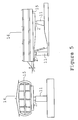
- the figure 1 represents the vertical structure 1 of the support tower 10 of a cable transport installation 20.
- the vertical structure 1 comprises several cylinders 2A to 2F with different diameters.
- the cylinder of the base 2A having the largest diameter is fixed, the next cylinder 2B has a smaller diameter to be able to operate in the cylinder of the base 2A and so on.
- the fixed base 2A of the vertical structure 1 is fixed to the concrete base (3) by a fastener 4 by means of screws.
- the pneumatic or hydraulic telescopic system 2 receives at its end the horizontal support structure 8 which, in turn, holds the pulleys 7 for the running of the cable 6, the seats 17 or the cabins 19.
- the horizontal support structure 8 is attached to the pneumatic or hydraulic telescopic system 2 of the vertical structure 1 by means of an interlocking attachment 9 and fixing screws to increase the resistance.
- This horizontal structure 8 undergoes a modification as regards the pulleys 7, presenting two rows of pulleys 7 instead of one, an upper row and a lower row. aligned so that the cable 6 scrolls between them.
- the cable 6, which runs between the two rows of pulleys 7, undergoes a certain pressure, either by the lower pulleys 7 or by the upper pulleys 7, accompanying the movement of the towers 10. Consequently the probability of the cable 6 coming off is practically nil.
- the pneumatic or hydraulic telescopic system 2 must be wrapped by a protective fuselage.
- This fuselage 5, itself also telescopic, will also be steel having a cylindrical and hollow shape.
- the cylinder 5A operates outside the fixed base 2A and the cylinder 5B operates outside the cylinder 5A. However the cylinder 5C operates inside the cylinder 5B and so on.
- the whole fuselage operates in a rail.
- the entire transport installation 20 must function as a unit, as a whole, either in the upward direction or in the downward direction or with the flexibility that the tension of the cable 6 allows it.
- the tension of the cable 6 can be compensated with the insertion of the pneumatic or hydraulic telescopic system 2 in the stations 14, 16, although other methods of compensation can be applied.
- the pneumatic or hydraulic telescopic system 2 is fixed between the pillar or the concrete pillars 11 and the structure 12 which supports the vessel 15 of the station 14, 16 by means of an attachment U and screws 13 with the dimensions required by the structure. It is attached to the upper part of the concrete pillar 11 by the same technical process used for attaching the pneumatic or hydraulic telescopic system 2 to the concrete footing 3.
- the pneumatic or hydraulic telescopic system 2 does not need dimensions such as those it has in the support pylons 10, once the function of the telescopic system 2 in the stations 14, 16 is to compensate for the voltage cable 6 up or down as needed.
- the pneumatic or hydraulic telescopic system 2 is always inserted between the concrete pillar 11 and the vessel 15 of the station, independently of the type of station 14,16.
- the detectors 18 are applied in the seats 17 or cabins 19 in a shielded box to protect them. Two detectors 18 must be applied in each vehicle 17,19, one on the left and one on the right side of the vehicle, both facing the direction of movement. The reading angle of the detectors must include the entire width of the seats 17 or cabins 19.
Claims (10)
- Hochkabeltransportanlage (20) fur Passagieren, mit Sessellifte oder Gondelbahnen ähnlichen Vehikeln, umfassend- mindestens einen Trag- und Zugkabel (6), das einen Ring zwischen einen Abfahrt- (14) und einen Ankunftbahnsteig (16) bildet;- mehrere an den obengenannte Kabel (6) befestigten Vehikeln (17, 19), mit einem vorbestimmten Abstand dazwischen;- eine motorisierte Antriebvorrichtung um das Kabel (6) in Kreisbewegung zu bringen, und mehrere Tragtürme (10) die das Kabel (6) während der gesamten Strecke halten;dadurch gekennzeichnet, daß ein teleskopisches System (2) der Abstand zwischen den Vehikeln und den Grund einstellen erlaubt, welches mehreren konzentrische Zylindern (2A bis 2F) mit unterschiedlichen Durchmessern umfaßt, die an den Tragtürme (10) und an den Abfahrt- (14) und Ankünftbahnsteigen (16) einngebracht sind, und über Detektoren (18) an den Vehikeln (17, 19) vefügen, die das Relief des Grundes bestimmen, um der Zusammenstoßen der Vehikeln (17, 19) mit Hindernissen zu vermeiden.
- Hochkabeltransportanlage nach Anspruch 1, dadurch gekennzeichnet, daß das teleskopisches System (2) an den Tragtürme (10) mit einem zylindrischen hohlen teleskopisch schützenden Rumpf ausgerüstet ist, welcher in seinem höher Ende eine horizontal stützende Struktur (8) mit zwei Reihen Rolle (7) und einem Kabel (6), das zwischen die Rolle (7) durchläuft, dadurch aufnimmt, daß das Kabel (6) dazwischen befestigen wird und kann nicht los werden wenn die Tragtürme (10) in aufsteigender und absteigender Bewegung gebracht werden.
- Hochkabeltransportanlage nach Ansprüche 1 und 2, dadurch gekennzeichnet, daß der Zylinder der Basis (2A) des teleskopisches System (2) unbeweglich und an einer Betonunterlage (3) mittels Befestigungsschrauben (4) befestig ist, und die horizontale stützende Struktur (8) ist an dem teleskopischen System (2) durch eine einfügende Fixierung (9) und mit Befestigungsschrauben befestigt, um die Festigkeit zu erhöhen.
- Hochkabeltransportanlage nach Anspruch 1, dadurch gekennzeichnet, daß in den Abfahrt- (14) und Ankünftbahnsteigen (16) das teleskopisches System (2) zwischen der oder den Betonstützen (11) und die Struktur (12) die das Schiff (15) des Bahnsteigs (14, 16) stutzt, eingefügt wird, und das System (2) an der genannten Struktur (12) durch eine U-förmige Fixierung und mit dazu passenden Befestigungsschrauben (13) befestigt wird.
- Hochkabeltransportanlage nach Ansprüche 3 und 4, dadurch gekennzeichnet, daß das teleskopische System (2) an der oberen Lage der Betonstütze (11) und an der Betonunterlage (3) mittels demselben teschiscen Mettode befestigt wird.
- Hochkabeltransportanlage nach Anspruch 1, dadurch gekennzeichnet, daß sie eine teleskopisches System (2) in den Tragtürme (10) und in den Abfahrt- (14) und Ankünftbahnsteigen (16) eingefügtes umfaßt, um die Tragtürme (10) hoch und runter, sofern notwendig, in Bewegung bringen.
- Hochkabeltransportanlage nach Anspruch 1, dadurch gekennzeichnet, daß sie Detektoren (18) umfaßt, die an den Vehikeln (17, 19) eingebracht sind, die das Relief des Grundes oder eventuelle Hindernissen während der gesamten Strecke und wenn die Installation auf eine niedrige Höhe funktioniert, feststellen, und die Tragtürmn (10) auf die erforderliche Höhe anpassen.
- Hochkabeltransportanlage nach Anspruch 1, dadurch gekennzeichnet, daß zwei Detektoren (18) auf jeden Vehikel (17, 19), der ein an der linken Seite und der andere an der rechten Seite, beide die Richtung der Bewegung zugewandt, eingebracht werden.
- Hochkabeltransportanlage nach Ansprüche 1 und 8, dadurch gekennzeichnet, daß der Leserwinkel der Detektoren (18) die gesamte Breite der Vehikeln (17, 19) umfaßt.
- Hochkabeltransportanlage nach Ansprüche 1 bis 9, dadurch gekennzeichnet, daß die Detektoren (18), bei der Erfassung eines Hindernissen, eine Information an eine Zentrale senden und diese die Tragtürme (10) wiederum in Bewegung setzt, und die Tragtürmen (10) mit dem Kabel (6) und die von ihm getragenen Vehikeln (17, 19) gemäß programmierte Richtlinie anpasst.
Applications Claiming Priority (2)
| Application Number | Priority Date | Filing Date | Title |
|---|---|---|---|
| PT1004705 | 2005-06-01 | ||
| PCT/PT2005/000015 WO2006130030A1 (fr) | 2005-06-01 | 2005-09-15 | Systeme telescopique pneumatique ou hydraulique pour les pylones et les gares des telesieges, telecabines et autres |
Publications (2)
| Publication Number | Publication Date |
|---|---|
| EP1885590A1 EP1885590A1 (de) | 2008-02-13 |
| EP1885590B1 true EP1885590B1 (de) | 2009-10-28 |
Family
ID=35559372
Family Applications (1)
| Application Number | Title | Priority Date | Filing Date |
|---|---|---|---|
| EP05782727A Not-in-force EP1885590B1 (de) | 2005-06-01 | 2005-09-15 | Pneumatisches oder hydraulisches teleskopsystem für türme und stationen von sesselliften, gondelbahnen und andere |
Country Status (6)
| Country | Link |
|---|---|
| US (1) | US20080121133A1 (de) |
| EP (1) | EP1885590B1 (de) |
| AT (1) | ATE446888T1 (de) |
| CA (1) | CA2606566A1 (de) |
| DE (1) | DE602005017433D1 (de) |
| WO (1) | WO2006130030A1 (de) |
Families Citing this family (7)
| Publication number | Priority date | Publication date | Assignee | Title |
|---|---|---|---|---|
| US8066200B2 (en) * | 2008-03-12 | 2011-11-29 | Hilltrac, Inc. | Hollow structural members, a rail system and methods of manufacturing |
| ITMI20080757A1 (it) * | 2008-04-24 | 2009-10-25 | Rolic Invest Sarl | Impianto di trasporto a fune |
| US8365471B2 (en) * | 2010-02-01 | 2013-02-05 | Aluma Tower Company, Inc. | Automated telescoping tower |
| JP6184752B2 (ja) * | 2013-05-29 | 2017-08-23 | 日本ケーブル株式会社 | 空中・水上両用索道設備 |
| NL2019395B1 (nl) * | 2017-08-04 | 2019-02-19 | Vermolen Amusement Nederland B V | Kabelbaansamenstel voor het over lange afstanden transporteren van passagiers. |
| USD898323S1 (en) * | 2018-01-08 | 2020-10-06 | Devi-Group Bv | Stair track rail |
| CN117897321A (zh) * | 2021-04-22 | 2024-04-16 | 杰弗里·洛雷施·斯特伦克 | 自推进式高架运输系统 |
Family Cites Families (16)
| Publication number | Priority date | Publication date | Assignee | Title |
|---|---|---|---|---|
| US3457876A (en) * | 1966-07-20 | 1969-07-29 | William Darwin Holden | Suspended railway system |
| CH488473A (fr) * | 1967-12-21 | 1970-04-15 | Mattel Inc | Jeu |
| DE2140244A1 (de) * | 1971-02-20 | 1973-02-22 | Egon Gelhard | Einrichtung zum transport von fluessigem, stueckigem oder staubfoermigem gut in gebieten mit arktischen verhaeltnissen |
| US3783792A (en) * | 1972-01-20 | 1974-01-08 | J Cullom | Repair facility for overhead crane |
| US3903807A (en) * | 1973-01-12 | 1975-09-09 | Averette T Lee | Mass rapid system |
| US4221170A (en) * | 1978-05-30 | 1980-09-09 | Slavos Koudelka | Monorail mountain slide |
| US4329926A (en) * | 1980-05-13 | 1982-05-18 | Sowder Tony R | Biased sheave frame for aerial tram |
| US4821647A (en) * | 1988-03-16 | 1989-04-18 | Powell Tyrone E | Downhill tubular guideway having an air suspension system for passenger car |
| JPH08531B2 (ja) * | 1991-07-23 | 1996-01-10 | 日本ケーブル株式会社 | 索道における救助装置 |
| US5193463A (en) * | 1992-04-10 | 1993-03-16 | Zygmunt Alexander Kunczynski And Alexander Jan Kunczynski | Rope tow apparatus and method |
| CH693091A5 (de) * | 1994-11-02 | 2003-02-28 | Garaventa Holding Ag | Bergungsfahrzeug für eine Seilbahn. |
| DE19850598A1 (de) * | 1997-11-25 | 1999-06-02 | Johann Wolf | Holzbringvorrichtung |
| US6393995B1 (en) * | 2000-07-03 | 2002-05-28 | Poma Of America, Inc. | Apparatus and method for use in aerial ropeways |
| ES2182687B1 (es) * | 2001-03-29 | 2004-04-01 | Domingo Bengoa Saez De Cortazar | Tren elevado. |
| FR2843928B1 (fr) * | 2002-09-04 | 2004-12-10 | Pomagalski Sa | Dispositif d'entrainement d'une poulie de renvoi d'un telesiege mono cable a pinces fixes. |
| FR2911314B1 (fr) * | 2007-01-16 | 2009-03-27 | Pomagalski Sa | Systeme de balanciers multiples a galets de compression et de support d'un cable d'une installation de transport a cable aerien. |
-
2005
- 2005-09-15 DE DE602005017433T patent/DE602005017433D1/de active Active
- 2005-09-15 US US11/885,319 patent/US20080121133A1/en not_active Abandoned
- 2005-09-15 AT AT05782727T patent/ATE446888T1/de not_active IP Right Cessation
- 2005-09-15 EP EP05782727A patent/EP1885590B1/de not_active Not-in-force
- 2005-09-15 WO PCT/PT2005/000015 patent/WO2006130030A1/fr active Application Filing
- 2005-09-15 CA CA002606566A patent/CA2606566A1/fr not_active Abandoned
Also Published As
| Publication number | Publication date |
|---|---|
| DE602005017433D1 (de) | 2009-12-10 |
| CA2606566A1 (fr) | 2006-12-07 |
| EP1885590A1 (de) | 2008-02-13 |
| WO2006130030A1 (fr) | 2006-12-07 |
| ATE446888T1 (de) | 2009-11-15 |
| US20080121133A1 (en) | 2008-05-29 |
Similar Documents
| Publication | Publication Date | Title |
|---|---|---|
| EP1885590B1 (de) | Pneumatisches oder hydraulisches teleskopsystem für türme und stationen von sesselliften, gondelbahnen und andere | |
| EP2585349B1 (de) | Installation mit oberleitungskabeln und damit versorgte fahrzeuge ohne aufhänger | |
| US8166885B2 (en) | Suspended cable amusement ride | |
| EP1858755A1 (de) | In einem turm eingeschlossener beweglicher ballon | |
| CN102740938B (zh) | 常平的乘客车厢的游乐乘载装置的固定轨道 | |
| US20090038499A1 (en) | Cable suspended, self leveling tram with self-propelled tractor bogie | |
| EP2810842B1 (de) | Wartungsvorrichtung und Seilschwebe-Transportanlage, insbesondere Sessellift oder Gondelbahn, die eine solche Vorrichtung umfasst | |
| EP2745895B1 (de) | Mobile plattform in einer zylindrischen struktur | |
| CA1284123C (fr) | Installation de transport a cables aeriens | |
| EP0263035B1 (de) | Schwebebahntransportsystem mit zwei Trage- und Zugkabeln, sowie versetzten Endstationsscheibenrädern | |
| EP3300488B1 (de) | Über ein freiluftkabel zu ziehendes transportfahrzeug und system mit einem fahrzueg solch eines typs | |
| EP0184476A1 (de) | Seilbahn mit mehreren Seilen | |
| FR2882985A1 (fr) | Ballon captif mobile dans une tour | |
| KR20200094414A (ko) | 와이어를 따라 이동하는 페달형 공중 놀이기구 | |
| EP0227540B1 (de) | Seilschwebebahn mit Wagen mit mindestens zwei Seilkupplungen | |
| US20070261589A1 (en) | Amusement ride | |
| FR2762292A1 (fr) | Systeme et procede d'assistance au decollage d'aeronefs et porte-avions equipe de ce systeme | |
| WO2011114023A2 (fr) | Installation aerienne de transport urbain | |
| EP4208380B1 (de) | Transporteinrichtung | |
| US20040187429A1 (en) | Drag reducing rotatable fairing usable on poles, posts and other structures | |
| EP0734930B1 (de) | Schwebebahn-Transportsystem mit Schienen | |
| EP0360710B1 (de) | Standseilbahn mit zylinderförmigen Wagen | |
| US20230242162A1 (en) | Cableway Vehicle Having Crossing Apparatus | |
| CH689115A5 (fr) | Installation de transport aérien par câbles. | |
| JP2784735B2 (ja) | リフト装置 |
Legal Events
| Date | Code | Title | Description |
|---|---|---|---|
| PUAI | Public reference made under article 153(3) epc to a published international application that has entered the european phase |
Free format text: ORIGINAL CODE: 0009012 |
|
| 17P | Request for examination filed |
Effective date: 20071220 |
|
| AK | Designated contracting states |
Kind code of ref document: A1 Designated state(s): AT BE BG CH CY CZ DE DK EE ES FI FR GB GR HU IE IS IT LI LT LU LV MC NL PL PT RO SE SI SK TR |
|
| DAX | Request for extension of the european patent (deleted) | ||
| GRAP | Despatch of communication of intention to grant a patent |
Free format text: ORIGINAL CODE: EPIDOSNIGR1 |
|
| GRAS | Grant fee paid |
Free format text: ORIGINAL CODE: EPIDOSNIGR3 |
|
| GRAA | (expected) grant |
Free format text: ORIGINAL CODE: 0009210 |
|
| AK | Designated contracting states |
Kind code of ref document: B1 Designated state(s): AT BE BG CH CY CZ DE DK EE ES FI FR GB GR HU IE IS IT LI LT LU LV MC NL PL PT RO SE SI SK TR |
|
| REG | Reference to a national code |
Ref country code: GB Ref legal event code: FG4D Free format text: NOT ENGLISH |
|
| REG | Reference to a national code |
Ref country code: CH Ref legal event code: EP |
|
| REG | Reference to a national code |
Ref country code: IE Ref legal event code: FG4D |
|
| REF | Corresponds to: |
Ref document number: 602005017433 Country of ref document: DE Date of ref document: 20091210 Kind code of ref document: P |
|
| LTIE | Lt: invalidation of european patent or patent extension |
Effective date: 20091028 |
|
| NLV1 | Nl: lapsed or annulled due to failure to fulfill the requirements of art. 29p and 29m of the patents act | ||
| PG25 | Lapsed in a contracting state [announced via postgrant information from national office to epo] |
Ref country code: FI Free format text: LAPSE BECAUSE OF FAILURE TO SUBMIT A TRANSLATION OF THE DESCRIPTION OR TO PAY THE FEE WITHIN THE PRESCRIBED TIME-LIMIT Effective date: 20091028 Ref country code: LT Free format text: LAPSE BECAUSE OF FAILURE TO SUBMIT A TRANSLATION OF THE DESCRIPTION OR TO PAY THE FEE WITHIN THE PRESCRIBED TIME-LIMIT Effective date: 20091028 Ref country code: IS Free format text: LAPSE BECAUSE OF FAILURE TO SUBMIT A TRANSLATION OF THE DESCRIPTION OR TO PAY THE FEE WITHIN THE PRESCRIBED TIME-LIMIT Effective date: 20100228 Ref country code: ES Free format text: LAPSE BECAUSE OF FAILURE TO SUBMIT A TRANSLATION OF THE DESCRIPTION OR TO PAY THE FEE WITHIN THE PRESCRIBED TIME-LIMIT Effective date: 20100208 Ref country code: PT Free format text: LAPSE BECAUSE OF FAILURE TO SUBMIT A TRANSLATION OF THE DESCRIPTION OR TO PAY THE FEE WITHIN THE PRESCRIBED TIME-LIMIT Effective date: 20100301 Ref country code: SE Free format text: LAPSE BECAUSE OF FAILURE TO SUBMIT A TRANSLATION OF THE DESCRIPTION OR TO PAY THE FEE WITHIN THE PRESCRIBED TIME-LIMIT Effective date: 20091028 |
|
| REG | Reference to a national code |
Ref country code: IE Ref legal event code: FD4D |
|
| PG25 | Lapsed in a contracting state [announced via postgrant information from national office to epo] |
Ref country code: LV Free format text: LAPSE BECAUSE OF FAILURE TO SUBMIT A TRANSLATION OF THE DESCRIPTION OR TO PAY THE FEE WITHIN THE PRESCRIBED TIME-LIMIT Effective date: 20091028 Ref country code: CY Free format text: LAPSE BECAUSE OF FAILURE TO SUBMIT A TRANSLATION OF THE DESCRIPTION OR TO PAY THE FEE WITHIN THE PRESCRIBED TIME-LIMIT Effective date: 20091028 Ref country code: PL Free format text: LAPSE BECAUSE OF FAILURE TO SUBMIT A TRANSLATION OF THE DESCRIPTION OR TO PAY THE FEE WITHIN THE PRESCRIBED TIME-LIMIT Effective date: 20091028 Ref country code: SI Free format text: LAPSE BECAUSE OF FAILURE TO SUBMIT A TRANSLATION OF THE DESCRIPTION OR TO PAY THE FEE WITHIN THE PRESCRIBED TIME-LIMIT Effective date: 20091028 |
|
| PG25 | Lapsed in a contracting state [announced via postgrant information from national office to epo] |
Ref country code: AT Free format text: LAPSE BECAUSE OF FAILURE TO SUBMIT A TRANSLATION OF THE DESCRIPTION OR TO PAY THE FEE WITHIN THE PRESCRIBED TIME-LIMIT Effective date: 20091028 |
|
| PG25 | Lapsed in a contracting state [announced via postgrant information from national office to epo] |
Ref country code: BG Free format text: LAPSE BECAUSE OF FAILURE TO SUBMIT A TRANSLATION OF THE DESCRIPTION OR TO PAY THE FEE WITHIN THE PRESCRIBED TIME-LIMIT Effective date: 20100128 Ref country code: DK Free format text: LAPSE BECAUSE OF FAILURE TO SUBMIT A TRANSLATION OF THE DESCRIPTION OR TO PAY THE FEE WITHIN THE PRESCRIBED TIME-LIMIT Effective date: 20091028 Ref country code: EE Free format text: LAPSE BECAUSE OF FAILURE TO SUBMIT A TRANSLATION OF THE DESCRIPTION OR TO PAY THE FEE WITHIN THE PRESCRIBED TIME-LIMIT Effective date: 20091028 Ref country code: RO Free format text: LAPSE BECAUSE OF FAILURE TO SUBMIT A TRANSLATION OF THE DESCRIPTION OR TO PAY THE FEE WITHIN THE PRESCRIBED TIME-LIMIT Effective date: 20091028 Ref country code: IE Free format text: LAPSE BECAUSE OF FAILURE TO SUBMIT A TRANSLATION OF THE DESCRIPTION OR TO PAY THE FEE WITHIN THE PRESCRIBED TIME-LIMIT Effective date: 20091028 |
|
| PG25 | Lapsed in a contracting state [announced via postgrant information from national office to epo] |
Ref country code: SK Free format text: LAPSE BECAUSE OF FAILURE TO SUBMIT A TRANSLATION OF THE DESCRIPTION OR TO PAY THE FEE WITHIN THE PRESCRIBED TIME-LIMIT Effective date: 20091028 Ref country code: CZ Free format text: LAPSE BECAUSE OF FAILURE TO SUBMIT A TRANSLATION OF THE DESCRIPTION OR TO PAY THE FEE WITHIN THE PRESCRIBED TIME-LIMIT Effective date: 20091028 |
|
| PLBE | No opposition filed within time limit |
Free format text: ORIGINAL CODE: 0009261 |
|
| STAA | Information on the status of an ep patent application or granted ep patent |
Free format text: STATUS: NO OPPOSITION FILED WITHIN TIME LIMIT |
|
| 26N | No opposition filed |
Effective date: 20100729 |
|
| PG25 | Lapsed in a contracting state [announced via postgrant information from national office to epo] |
Ref country code: GR Free format text: LAPSE BECAUSE OF FAILURE TO SUBMIT A TRANSLATION OF THE DESCRIPTION OR TO PAY THE FEE WITHIN THE PRESCRIBED TIME-LIMIT Effective date: 20100129 |
|
| BERE | Be: lapsed |
Owner name: AMERICO CESAR, SOUSA JAQUES Effective date: 20100930 |
|
| PG25 | Lapsed in a contracting state [announced via postgrant information from national office to epo] |
Ref country code: IT Free format text: LAPSE BECAUSE OF FAILURE TO SUBMIT A TRANSLATION OF THE DESCRIPTION OR TO PAY THE FEE WITHIN THE PRESCRIBED TIME-LIMIT Effective date: 20091028 |
|
| PG25 | Lapsed in a contracting state [announced via postgrant information from national office to epo] |
Ref country code: MC Free format text: LAPSE BECAUSE OF NON-PAYMENT OF DUE FEES Effective date: 20100930 |
|
| REG | Reference to a national code |
Ref country code: CH Ref legal event code: PL |
|
| GBPC | Gb: european patent ceased through non-payment of renewal fee |
Effective date: 20100915 |
|
| REG | Reference to a national code |
Ref country code: FR Ref legal event code: ST Effective date: 20110531 |
|
| REG | Reference to a national code |
Ref country code: DE Ref legal event code: R119 Ref document number: 602005017433 Country of ref document: DE Effective date: 20110401 |
|
| PG25 | Lapsed in a contracting state [announced via postgrant information from national office to epo] |
Ref country code: DE Free format text: LAPSE BECAUSE OF NON-PAYMENT OF DUE FEES Effective date: 20110401 Ref country code: FR Free format text: LAPSE BECAUSE OF NON-PAYMENT OF DUE FEES Effective date: 20100930 Ref country code: LI Free format text: LAPSE BECAUSE OF NON-PAYMENT OF DUE FEES Effective date: 20100930 Ref country code: BE Free format text: LAPSE BECAUSE OF NON-PAYMENT OF DUE FEES Effective date: 20100930 Ref country code: CH Free format text: LAPSE BECAUSE OF NON-PAYMENT OF DUE FEES Effective date: 20100930 |
|
| PG25 | Lapsed in a contracting state [announced via postgrant information from national office to epo] |
Ref country code: GB Free format text: LAPSE BECAUSE OF NON-PAYMENT OF DUE FEES Effective date: 20100915 |
|
| PG25 | Lapsed in a contracting state [announced via postgrant information from national office to epo] |
Ref country code: LU Free format text: LAPSE BECAUSE OF NON-PAYMENT OF DUE FEES Effective date: 20100915 Ref country code: HU Free format text: LAPSE BECAUSE OF FAILURE TO SUBMIT A TRANSLATION OF THE DESCRIPTION OR TO PAY THE FEE WITHIN THE PRESCRIBED TIME-LIMIT Effective date: 20100429 Ref country code: NL Free format text: LAPSE BECAUSE OF FAILURE TO SUBMIT A TRANSLATION OF THE DESCRIPTION OR TO PAY THE FEE WITHIN THE PRESCRIBED TIME-LIMIT Effective date: 20091028 |
|
| PG25 | Lapsed in a contracting state [announced via postgrant information from national office to epo] |
Ref country code: TR Free format text: LAPSE BECAUSE OF FAILURE TO SUBMIT A TRANSLATION OF THE DESCRIPTION OR TO PAY THE FEE WITHIN THE PRESCRIBED TIME-LIMIT Effective date: 20091028 |