EP2745895B1 - Mobile plattform in einer zylindrischen struktur - Google Patents
Mobile plattform in einer zylindrischen struktur Download PDFInfo
- Publication number
- EP2745895B1 EP2745895B1 EP13198598.8A EP13198598A EP2745895B1 EP 2745895 B1 EP2745895 B1 EP 2745895B1 EP 13198598 A EP13198598 A EP 13198598A EP 2745895 B1 EP2745895 B1 EP 2745895B1
- Authority
- EP
- European Patent Office
- Prior art keywords
- platform
- cable
- assembly
- passengers
- cylindrical structure
- Prior art date
- Legal status (The legal status is an assumption and is not a legal conclusion. Google has not performed a legal analysis and makes no representation as to the accuracy of the status listed.)
- Active
Links
Images

Classifications
-
- B—PERFORMING OPERATIONS; TRANSPORTING
- B66—HOISTING; LIFTING; HAULING
- B66B—ELEVATORS; ESCALATORS OR MOVING WALKWAYS
- B66B11/00—Main component parts of lifts in, or associated with, buildings or other structures
-
- E—FIXED CONSTRUCTIONS
- E04—BUILDING
- E04H—BUILDINGS OR LIKE STRUCTURES FOR PARTICULAR PURPOSES; SWIMMING OR SPLASH BATHS OR POOLS; MASTS; FENCING; TENTS OR CANOPIES, IN GENERAL
- E04H12/00—Towers; Masts or poles; Chimney stacks; Water-towers; Methods of erecting such structures
- E04H12/18—Towers; Masts or poles; Chimney stacks; Water-towers; Methods of erecting such structures movable or with movable sections, e.g. rotatable or telescopic
-
- A—HUMAN NECESSITIES
- A63—SPORTS; GAMES; AMUSEMENTS
- A63G—MERRY-GO-ROUNDS; SWINGS; ROCKING-HORSES; CHUTES; SWITCHBACKS; SIMILAR DEVICES FOR PUBLIC AMUSEMENT
- A63G1/00—Roundabouts
- A63G1/44—Roundabouts with turntables moved up and down
-
- A—HUMAN NECESSITIES
- A63—SPORTS; GAMES; AMUSEMENTS
- A63G—MERRY-GO-ROUNDS; SWINGS; ROCKING-HORSES; CHUTES; SWITCHBACKS; SIMILAR DEVICES FOR PUBLIC AMUSEMENT
- A63G31/00—Amusement arrangements
- A63G31/02—Amusement arrangements with moving substructures
- A63G31/10—Amusement arrangements with moving substructures with escalators or similar moving substructures
-
- A—HUMAN NECESSITIES
- A63—SPORTS; GAMES; AMUSEMENTS
- A63G—MERRY-GO-ROUNDS; SWINGS; ROCKING-HORSES; CHUTES; SWITCHBACKS; SIMILAR DEVICES FOR PUBLIC AMUSEMENT
- A63G31/00—Amusement arrangements
- A63G31/02—Amusement arrangements with moving substructures
-
- B—PERFORMING OPERATIONS; TRANSPORTING
- B81—MICROSTRUCTURAL TECHNOLOGY
- B81C—PROCESSES OR APPARATUS SPECIALLY ADAPTED FOR THE MANUFACTURE OR TREATMENT OF MICROSTRUCTURAL DEVICES OR SYSTEMS
- B81C1/00—Manufacture or treatment of devices or systems in or on a substrate
Definitions
- the invention relates to a mobile platform in a cylindrical structure.
- a mobile platform is designed to receive passengers and is intended to be installed for example in amusement parks and tourist sites.
- the US patent US 7,926,787 describes for example a platform designed to receive passengers and a lifting mechanism of the platform by means of inflatable pockets for moving up and down the platform.
- a platform suspended by a cable to the boom of a crane is for example used to receive diners and organize a dinner or an event at altitude combining catering and attraction (see the description on the so-called internet www.dinnerinthesky.com ).
- the published patent FR 2882986 in the name of the applicant describes a basket system suspended from a balloon itself moving in a tower, the basket being able to receive passengers.
- the suspended systems cited, however, have difficulty balancing the platform or the platform once the passengers on board and the disadvantage of presenting elements above the passengers.
- elevators allow passengers to be carried inside a cabin.
- the cabin is either suspended at a central fixed point, or pushed by a system located at the bottom, for example a cylinder, reducing the feeling felt by passengers.
- the proximity of the supporting structure ensuring the In addition, for obvious safety reasons, cabin guidance requires that passengers be secured inside a closed cabin that can, at best, be glazed.
- lifting platform systems are composed of a fixed mast (tower) and a lateral or annular nacelle surrounding the mast and being able to translate along the mast.
- the tower has a size and proximity with the basket that prohibits a 360 ° open view.
- the height of elevation of such a platform is also limited because of stability constraints.
- US 1,034,864 describes a device consisting of a tower comprising uprights, reinforcements and platforms. Between the uprights, is mounted a spiral track. In the center of the tower is mounted a vertical tree with channels. Around the vertical shaft is mounted a structure comprising transport cars, said structure being connected to the channels and disposed on the spiral track by wheels.
- the present invention has an ascension platform for receiving passengers that allows a very high stability while offering passengers sensations of elevation in the open air, with minimal obstruction for a panoramic view.
- the invention relates to an assembly comprising a platform for receiving passengers, a cylindrical structure, the platform being movable in the cylindrical structure.
- the cylindrical structure comprises, in a variant, at least three vertical columns. The three columns can be connected by braces.
- the cylindrical structure is for example circular base with curved braces helical; or more simply cylindrical triangular base.
- the assembly comprises at least three carriages integral with the platform and adapted to be hooked to drive cables housed in guide rails of at least three of the columns of the cylindrical structure.
- the assembly comprises, for each carriage, a fall arrest mechanism.
- the fall arrest mechanism comprises a finger secured to the carriage and a rack attached to the guide rail, the finger being intended to abut against a tooth of the rack in the event of loss of tension in the cable.
- the platform comprises a central plate and beams extending from the central plate and at the ends of which the carriages are fixed.
- the assembly includes a motor associated with each drive cable for controlling the cable drive movement in one direction or the other.
- the assembly comprises a control unit adapted to synchronize the drive motors of the cables.
- the assembly comprises a cover element for the protection of passengers against the weather, fixed above the platform.
- the covering element is for example an inflatable element of ellipsoidal shape.
- FIGS. 1A and 1B illustrate an assembly formed of a platform 100 and a cylindrical structure, or tower, 200, in one embodiment of the invention, respectively with the platform on the ground and with the elevated platform.
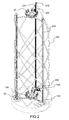
- the figure 2 illustrates in greater detail an exemplary embodiment of the assembly illustrated on the Figures 1A and 1B .
- the tower 200 comprises a vertical structure with at least three posts 250, two of which are visible on the Figures 1A and 1B .
- the tower may also comprise walls between the vertical posts or braces connecting the vertical posts to ensure the rigidity of the structure, for example braces 260 forming sleepers or crossed propellers, as illustrated in FIG. figure 2 .
- Posts and braces are for example metal, tube or profiles.
- the platform 100 for receiving passengers is mobile in the tower 200. It is for example driven upward in the tower by cables 220 of a drive system.
- the tower is substantially cylindrical circular base and the circular platform is provided with arms or beams to distance it from the tower.
- the section of the cylindrical structure forming the tower may be any, for example hexagonal, triangular, or square.
- platform 100 optionally includes seats 150 for embarking passengers.
- the seats are for example distributed around a central platform 110 of the platform, itself connected to the drive system by beams or arm 120.
- the seats can be turned inward or outward of the tower.
- passengers benefit from a greater user-friendliness; in the second case, they have a direct view of the panorama.
- the seats can also rotate on their own, giving passengers a 360 ° view.
- the platform may also include a roof element, or roof 400, to protect the passengers from bad weather.
- the platform is not suspended but directly connected to the drive system, the stability is significantly improved and a large number of passengers can be distributed around the central plateau, even irregularly.
- Passengers are for example distributed on a circle which must have a diameter sufficient to comfortably seat all passengers.
- the tower can have a height between 30 m and 80 m to allow a good panoramic view when passengers are raised by means of the platform. Furthermore, since the platform is directly connected to the drive system, it is possible for passengers in the high position ( Figure 1B ) of the platform, to have a completely unobstructed view, including of the structure itself.
- the posts 250 comprise for example guide rails in which are placed the drive cables 220, for example cables of the type used for lifts.
- the guide rails are adapted to respectively accommodate three carriages 300 integral with each of the ends of the beams 120 of the platform.
- Each cable can extend from a winch 160 located at the base of the tower to a return pulley 210 located at the top of the tower and has a return run from the pulley 210 to the winch 160.
- the winch can be of the type used for elevator installations; it can be associated with a control unit to control the direction of rotation of the cable 220 and regulate its speed; the control unit also receives the synchronization of the movement of the three carriages so that the platform goes up straight in the tower, that is by keeping the central plateau 110 horizontal.
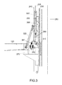
- the figure 3 shows a detailed view of the drive system of the platform according to an exemplary embodiment.
- the figure 3 shows a portion of a pole 250 of the tower and a portion of a beam 120 connected to the central platform of the platform.
- the figure 3 watch also a carriage 300 housed in guide rails of the pole 250 and attached to a drive cable 220.
- the cable 220 has two cable strands on either side of the return pulley 210 ( Figure 1A, 1B ); a first strand of cable on which is hung the carriage defining a drive path and a second cable strand defining a return path to the winding winch of the cable 160.
- Each winch can be associated with a motor to control the movement cable in one direction or the other.
- the figure 3 also shows a side sectional view of a carriage 300 of substantially parallelepiped shape adapted to a C-shaped profile (240) inside which it slides.
- the C-section is hooked to a post 250 of the cylindrical supporting structure.
- the carriage is towed by the cable 220.
- Lateral rollers 350 for example four in number, rest on the right and left sides of the C-profile.
- the transverse rollers 360 are supported on the bottom of the C-section or on these returns.
- Arms or beams 120 of the platform rests on the carriage of the shoe through a flexible damping element 370 ® rubber mount type which provides a flexible interface.
- a sling 320 suspends the arm to the carriage.
- Its length is adjustable so as to adjust the distribution of forces between the sling (traction) and the silentbloc (compression) and obtain an optimized behavior of the platform. Stronger traction in the slings will result in greater freedom of movement of the platform. A stronger compression of the silentbloc will result in a more restrictive refocusing of the platform.
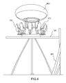
- the figure 4 illustrates an exemplary embodiment of a platform, comprising a central plate 110 connected to the cylindrical structure by beams 120.
- the central plate is for example equipped with seats 150 for passengers, distributed around a structure forming a bar.
- the entire bar and passengers is protected by a cover element 400.
- the cover element can be any and may include for example an advertising sign. It may be for example an inflatable element.
- this inflatable element may have an ellipsoidal shape, as shown in FIG. figure 4 to provide minimum wind resistance when the platform is in a raised position and the cover element protrudes from the top edge of the tower.
- the assembly formed of the mobile platform and the cylindrical structure in which the platform is intended to elevate comprises various variants, modifications and improvements which will be apparent to the user. Those skilled in the art, it being understood that these various variants, modifications and improvements fall within the scope of the invention, as defined by the following claims.
Landscapes
- Engineering & Computer Science (AREA)
- Architecture (AREA)
- Civil Engineering (AREA)
- Structural Engineering (AREA)
- Mechanical Engineering (AREA)
- Refuge Islands, Traffic Blockers, Or Guard Fence (AREA)
- Platform Screen Doors And Railroad Systems (AREA)
- Types And Forms Of Lifts (AREA)
- Forklifts And Lifting Vehicles (AREA)
Claims (7)
- Einheit, bestehend aus:- einer Plattform (100), zur Aufnahme von Passagieren bestimmt,- einer zylindrischen Struktur (200), die mindestens drei vertikale Pfosten (250) umfasst, wobei die Plattform in der zylindrischen Struktur mobil ist,wobei die Einheit dadurch charakterisiert ist, dass sie mindestens drei Wagen (300) umfasst, die fest mit der Plattform verbunden sind und geeignet sind, an Antriebskabeln (220) aufgehängt zu werden, die in Führungsschienen von mindestens drei der Pfosten der zylindrischen Struktur untergebracht sind.
- Einheit nach Anspruch 1, die unter anderem für jeden Wagen einen Auffang-Mechanismus umfasst, der einen Finger (310) aufweist, der fest mit dem Wagen verbunden ist, und eine Zahnstange (230), die an der Führungsschiene befestigt ist, wobei der Finger dazu bestimmt ist, gegen einen Zahn der Zahnstange anzuliegen, falls es im Kabel zu einem Spannungsverlust kommt.
- Einheit nach einem der Ansprüche 1 oder 2, dadurch gekennzeichnet, dass die Plattform (100) ein Mittelplateau (110) und Träger (120) umfasst, die vom Mittelplateau aus abgehen, wobei die Wagen an den Enden der Träger befestigt sind.
- Einheit nach einem der Ansprüche 1 bis 3, dadurch gekennzeichnet, dass sie einen mit jedem Antriebskabel verbundenen Motor umfasst, um die Antriebsbewegung des Kabels in die eine Richtung oder in die andere zu steuern.
- Einheit nach Anspruch 4, dadurch gekennzeichnet, dass sie eine Kontrollanlage umfasst, die geeignet ist, die Antriebsmotoren der Kabel zu synchronisieren.
- Einheit nach einem der Ansprüche 1 bis 5, dadurch gekennzeichnet, dass sie ein Abdeckelement (400) für den Schutz der Passagiere vor schlechter Witterung umfasst, das über der Plattform befestigt ist.
- Einheit nach Anspruch 6, dadurch gekennzeichnet, dass das Abdeckelement ein aufblasbares Element von elliptischer Form ist.
Priority Applications (1)
| Application Number | Priority Date | Filing Date | Title |
|---|---|---|---|
| PL13198598T PL2745895T3 (pl) | 2012-12-20 | 2013-12-19 | Platforma mobilna w strukturze cylindrycznej |
Applications Claiming Priority (1)
| Application Number | Priority Date | Filing Date | Title |
|---|---|---|---|
| FR1262501A FR2999948B1 (fr) | 2012-12-20 | 2012-12-20 | Plateforme mobile dans une structure cylindrique |
Publications (2)
| Publication Number | Publication Date |
|---|---|
| EP2745895A1 EP2745895A1 (de) | 2014-06-25 |
| EP2745895B1 true EP2745895B1 (de) | 2016-09-28 |
Family
ID=48083258
Family Applications (1)
| Application Number | Title | Priority Date | Filing Date |
|---|---|---|---|
| EP13198598.8A Active EP2745895B1 (de) | 2012-12-20 | 2013-12-19 | Mobile plattform in einer zylindrischen struktur |
Country Status (8)
| Country | Link |
|---|---|
| US (1) | US9133642B2 (de) |
| EP (1) | EP2745895B1 (de) |
| CN (1) | CN103877729B (de) |
| BR (1) | BR102013033156B1 (de) |
| ES (1) | ES2608658T3 (de) |
| FR (1) | FR2999948B1 (de) |
| PL (1) | PL2745895T3 (de) |
| PT (1) | PT2745895T (de) |
Families Citing this family (6)
| Publication number | Priority date | Publication date | Assignee | Title |
|---|---|---|---|---|
| CN105749555B (zh) * | 2016-03-29 | 2017-12-01 | 温州联科知识产权服务有限公司 | 一种娱乐用模拟高空升降体验装置 |
| GB201619701D0 (en) | 2016-11-22 | 2017-01-04 | Tower Visions Ltd Liability Partnership | Observation tower assembly |
| CN107420422B (zh) * | 2017-05-27 | 2023-08-11 | 广东金马游乐股份有限公司 | 一种滑行架的旋转机构 |
| US11058959B2 (en) * | 2019-03-14 | 2021-07-13 | Universal City Studios Llc | Vertical motion drive system for a ride system |
| FR3110565B1 (fr) | 2020-05-19 | 2022-10-07 | Aerogroupe | Ensemble avec plateforme mobile pour passagers |
| CN114538338A (zh) * | 2022-02-24 | 2022-05-27 | 上海送变电工程有限公司 | 一种抱杆提升驱动装置和落地摇臂抱杆提升架 |
Family Cites Families (15)
| Publication number | Priority date | Publication date | Assignee | Title |
|---|---|---|---|---|
| US989821A (en) * | 1910-03-21 | 1911-04-18 | Joseph J Stoetzel | Pneumatic observation-tower. |
| US1034864A (en) * | 1912-04-29 | 1912-08-06 | Alfred Best | Amusement device. |
| US1207914A (en) * | 1916-05-02 | 1916-12-12 | John Low Kerr | Amusement apparatus. |
| JPS5227571B2 (de) * | 1972-04-14 | 1977-07-21 | ||
| FR2697227A1 (fr) * | 1992-07-20 | 1994-04-29 | Beuret Patrice | Ascenseur à ballon. |
| US5421783A (en) * | 1993-07-16 | 1995-06-06 | Bungee Adventures | Human slingshot machine |
| US5649866A (en) * | 1996-03-22 | 1997-07-22 | Balwanz; C. Grant | Amusement ride system |
| CN2605044Y (zh) * | 2003-03-18 | 2004-03-03 | 滕桂龙 | 蹦极旋风游乐装置 |
| DE102005004878B4 (de) | 2005-02-03 | 2015-01-08 | Robert Bosch Gmbh | Mikromechanischer kapazitiver Drucksensor und entsprechendes Herstellungsverfahren |
| FR2882985A1 (fr) * | 2005-03-08 | 2006-09-15 | Aerogroupe S A R L | Ballon captif mobile dans une tour |
| FR2882986B1 (fr) | 2005-03-08 | 2010-03-12 | Aerogroupe S A R L | Ballon captif mobile dans une tour |
| US7926787B2 (en) | 2006-11-21 | 2011-04-19 | Blue Sky Decks, Llc | Elevated platform and method of elevating the same |
| DE102008005859B4 (de) * | 2008-01-14 | 2018-10-18 | Robocoaster Ltd. | Fahrgeschäft |
| CN201768352U (zh) * | 2010-05-24 | 2011-03-23 | 温州南方游乐设备工程有限公司 | 高空飞翔游艺机 |
| CN202201600U (zh) * | 2011-08-29 | 2012-04-25 | 深圳市远望淦拓科技有限公司 | 一种升降游乐设备的安全制动装置 |
-
2012
- 2012-12-20 FR FR1262501A patent/FR2999948B1/fr not_active Expired - Fee Related
-
2013
- 2013-12-19 PT PT131985988T patent/PT2745895T/pt unknown
- 2013-12-19 PL PL13198598T patent/PL2745895T3/pl unknown
- 2013-12-19 EP EP13198598.8A patent/EP2745895B1/de active Active
- 2013-12-19 ES ES13198598.8T patent/ES2608658T3/es active Active
- 2013-12-20 BR BR102013033156-2A patent/BR102013033156B1/pt active IP Right Grant
- 2013-12-20 CN CN201310712945.1A patent/CN103877729B/zh active Active
- 2013-12-20 US US14/135,767 patent/US9133642B2/en active Active
Also Published As
| Publication number | Publication date |
|---|---|
| ES2608658T3 (es) | 2017-04-12 |
| BR102013033156A2 (pt) | 2020-09-01 |
| FR2999948A1 (fr) | 2014-06-27 |
| FR2999948B1 (fr) | 2016-04-29 |
| EP2745895A1 (de) | 2014-06-25 |
| US20140174854A1 (en) | 2014-06-26 |
| US9133642B2 (en) | 2015-09-15 |
| HK1197207A1 (en) | 2015-01-09 |
| CN103877729B (zh) | 2017-11-14 |
| CN103877729A (zh) | 2014-06-25 |
| PT2745895T (pt) | 2016-12-27 |
| PL2745895T3 (pl) | 2017-08-31 |
| BR102013033156B1 (pt) | 2021-10-05 |
Similar Documents
| Publication | Publication Date | Title |
|---|---|---|
| WO2006095082A1 (fr) | Ballon captif mobile dans une tour | |
| EP2745895B1 (de) | Mobile plattform in einer zylindrischen struktur | |
| US8683925B2 (en) | Zip line transport trolley system | |
| EP3300488B1 (de) | Über ein freiluftkabel zu ziehendes transportfahrzeug und system mit einem fahrzueg solch eines typs | |
| FR2577510A1 (fr) | Bateau de transbordement vertical et horizontal | |
| US20160304101A1 (en) | Zip line attraction and methods | |
| CA2539347C (fr) | Pont destine a franchir notamment une passe d'une voie de navigation | |
| FR2882985A1 (fr) | Ballon captif mobile dans une tour | |
| US7927223B2 (en) | Amusement ride | |
| EP0803466B1 (de) | Verfahren und Vorrichtung zum sicheren Besteigen einer Kabine, insbesondere auf einem Turmkran | |
| EP2541536B1 (de) | Anzeigevorrichtung | |
| KR101886261B1 (ko) | 전망대식 서비스 제공장치 | |
| FR2622332A1 (fr) | Panneau publicitaire protege par basculement ou pivotement contre la deterioration due au vent ou a la tempete | |
| EP1885590B1 (de) | Pneumatisches oder hydraulisches teleskopsystem für türme und stationen von sesselliften, gondelbahnen und andere | |
| FR3110565A1 (fr) | Ensemble avec plateforme mobile pour passagers | |
| BE1031957B1 (fr) | Dispositif de protection contre chute de roches pour plate-forme de route d'excavation profonde | |
| FR2584300A1 (fr) | But de basket-ball relevable avec panneau reglable en hauteur | |
| WO2017203167A1 (fr) | Véhicule de transport destiné à être tracté par un câble aérien et installation comprenant un tel véhicule | |
| FR2970718A1 (fr) | Portique a levage elastique | |
| CA1303543C (fr) | Remonte-pente | |
| FR2795375A1 (fr) | Dispositif de securite pour une station d'arrivee d'une installation de convoyage | |
| FR2743732A1 (fr) | Tourniquet aerien pour etre humain | |
| FR2707098A1 (fr) | Dispositif mobile d'accès à des produits stockés en hauteur, notamment aux fûts d'un chai de stockage. | |
| EP0787509A2 (de) | Stützvorrichtung für ein Basketballzielbrett, Spielfeld und Sporthalle mit einer solchen Stützvorrichtung versehen | |
| EP2990083A1 (de) | Vorrichtung, die ein tor für ballsportarten mit einem höhenregulierbaren querbalken bildet |
Legal Events
| Date | Code | Title | Description |
|---|---|---|---|
| PUAI | Public reference made under article 153(3) epc to a published international application that has entered the european phase |
Free format text: ORIGINAL CODE: 0009012 |
|
| 17P | Request for examination filed |
Effective date: 20131219 |
|
| AK | Designated contracting states |
Kind code of ref document: A1 Designated state(s): AL AT BE BG CH CY CZ DE DK EE ES FI FR GB GR HR HU IE IS IT LI LT LU LV MC MK MT NL NO PL PT RO RS SE SI SK SM TR |
|
| AX | Request for extension of the european patent |
Extension state: BA ME |
|
| R17P | Request for examination filed (corrected) |
Effective date: 20141128 |
|
| RBV | Designated contracting states (corrected) |
Designated state(s): AL AT BE BG CH CY CZ DE DK EE ES FI FR GB GR HR HU IE IS IT LI LT LU LV MC MK MT NL NO PL PT RO RS SE SI SK SM TR |
|
| GRAP | Despatch of communication of intention to grant a patent |
Free format text: ORIGINAL CODE: EPIDOSNIGR1 |
|
| INTG | Intention to grant announced |
Effective date: 20160419 |
|
| GRAS | Grant fee paid |
Free format text: ORIGINAL CODE: EPIDOSNIGR3 |
|
| GRAA | (expected) grant |
Free format text: ORIGINAL CODE: 0009210 |
|
| AK | Designated contracting states |
Kind code of ref document: B1 Designated state(s): AL AT BE BG CH CY CZ DE DK EE ES FI FR GB GR HR HU IE IS IT LI LT LU LV MC MK MT NL NO PL PT RO RS SE SI SK SM TR |
|
| REG | Reference to a national code |
Ref country code: GB Ref legal event code: FG4D Free format text: NOT ENGLISH |
|
| REG | Reference to a national code |
Ref country code: CH Ref legal event code: EP |
|
| REG | Reference to a national code |
Ref country code: AT Ref legal event code: REF Ref document number: 832249 Country of ref document: AT Kind code of ref document: T Effective date: 20161015 |
|
| REG | Reference to a national code |
Ref country code: IE Ref legal event code: FG4D Free format text: LANGUAGE OF EP DOCUMENT: FRENCH |
|
| REG | Reference to a national code |
Ref country code: DE Ref legal event code: R096 Ref document number: 602013012122 Country of ref document: DE |
|
| REG | Reference to a national code |
Ref country code: FR Ref legal event code: PLFP Year of fee payment: 4 |
|
| REG | Reference to a national code |
Ref country code: PT Ref legal event code: SC4A Ref document number: 2745895 Country of ref document: PT Date of ref document: 20161227 Kind code of ref document: T Free format text: AVAILABILITY OF NATIONAL TRANSLATION Effective date: 20161220 |
|
| REG | Reference to a national code |
Ref country code: NL Ref legal event code: FP |
|
| REG | Reference to a national code |
Ref country code: LT Ref legal event code: MG4D |
|
| PG25 | Lapsed in a contracting state [announced via postgrant information from national office to epo] |
Ref country code: HR Free format text: LAPSE BECAUSE OF FAILURE TO SUBMIT A TRANSLATION OF THE DESCRIPTION OR TO PAY THE FEE WITHIN THE PRESCRIBED TIME-LIMIT Effective date: 20160928 Ref country code: LT Free format text: LAPSE BECAUSE OF FAILURE TO SUBMIT A TRANSLATION OF THE DESCRIPTION OR TO PAY THE FEE WITHIN THE PRESCRIBED TIME-LIMIT Effective date: 20160928 Ref country code: NO Free format text: LAPSE BECAUSE OF FAILURE TO SUBMIT A TRANSLATION OF THE DESCRIPTION OR TO PAY THE FEE WITHIN THE PRESCRIBED TIME-LIMIT Effective date: 20161228 Ref country code: RS Free format text: LAPSE BECAUSE OF FAILURE TO SUBMIT A TRANSLATION OF THE DESCRIPTION OR TO PAY THE FEE WITHIN THE PRESCRIBED TIME-LIMIT Effective date: 20160928 Ref country code: FI Free format text: LAPSE BECAUSE OF FAILURE TO SUBMIT A TRANSLATION OF THE DESCRIPTION OR TO PAY THE FEE WITHIN THE PRESCRIBED TIME-LIMIT Effective date: 20160928 |
|
| REG | Reference to a national code |
Ref country code: AT Ref legal event code: MK05 Ref document number: 832249 Country of ref document: AT Kind code of ref document: T Effective date: 20160928 |
|
| PG25 | Lapsed in a contracting state [announced via postgrant information from national office to epo] |
Ref country code: GR Free format text: LAPSE BECAUSE OF FAILURE TO SUBMIT A TRANSLATION OF THE DESCRIPTION OR TO PAY THE FEE WITHIN THE PRESCRIBED TIME-LIMIT Effective date: 20161229 Ref country code: SE Free format text: LAPSE BECAUSE OF FAILURE TO SUBMIT A TRANSLATION OF THE DESCRIPTION OR TO PAY THE FEE WITHIN THE PRESCRIBED TIME-LIMIT Effective date: 20160928 Ref country code: LV Free format text: LAPSE BECAUSE OF FAILURE TO SUBMIT A TRANSLATION OF THE DESCRIPTION OR TO PAY THE FEE WITHIN THE PRESCRIBED TIME-LIMIT Effective date: 20160928 |
|
| REG | Reference to a national code |
Ref country code: ES Ref legal event code: FG2A Ref document number: 2608658 Country of ref document: ES Kind code of ref document: T3 Effective date: 20170412 |
|
| PG25 | Lapsed in a contracting state [announced via postgrant information from national office to epo] |
Ref country code: RO Free format text: LAPSE BECAUSE OF FAILURE TO SUBMIT A TRANSLATION OF THE DESCRIPTION OR TO PAY THE FEE WITHIN THE PRESCRIBED TIME-LIMIT Effective date: 20160928 Ref country code: EE Free format text: LAPSE BECAUSE OF FAILURE TO SUBMIT A TRANSLATION OF THE DESCRIPTION OR TO PAY THE FEE WITHIN THE PRESCRIBED TIME-LIMIT Effective date: 20160928 |
|
| PG25 | Lapsed in a contracting state [announced via postgrant information from national office to epo] |
Ref country code: CZ Free format text: LAPSE BECAUSE OF FAILURE TO SUBMIT A TRANSLATION OF THE DESCRIPTION OR TO PAY THE FEE WITHIN THE PRESCRIBED TIME-LIMIT Effective date: 20160928 Ref country code: SK Free format text: LAPSE BECAUSE OF FAILURE TO SUBMIT A TRANSLATION OF THE DESCRIPTION OR TO PAY THE FEE WITHIN THE PRESCRIBED TIME-LIMIT Effective date: 20160928 Ref country code: SM Free format text: LAPSE BECAUSE OF FAILURE TO SUBMIT A TRANSLATION OF THE DESCRIPTION OR TO PAY THE FEE WITHIN THE PRESCRIBED TIME-LIMIT Effective date: 20160928 Ref country code: IS Free format text: LAPSE BECAUSE OF FAILURE TO SUBMIT A TRANSLATION OF THE DESCRIPTION OR TO PAY THE FEE WITHIN THE PRESCRIBED TIME-LIMIT Effective date: 20170128 Ref country code: AT Free format text: LAPSE BECAUSE OF FAILURE TO SUBMIT A TRANSLATION OF THE DESCRIPTION OR TO PAY THE FEE WITHIN THE PRESCRIBED TIME-LIMIT Effective date: 20160928 Ref country code: BG Free format text: LAPSE BECAUSE OF FAILURE TO SUBMIT A TRANSLATION OF THE DESCRIPTION OR TO PAY THE FEE WITHIN THE PRESCRIBED TIME-LIMIT Effective date: 20161228 |
|
| REG | Reference to a national code |
Ref country code: DE Ref legal event code: R097 Ref document number: 602013012122 Country of ref document: DE |
|
| PG25 | Lapsed in a contracting state [announced via postgrant information from national office to epo] |
Ref country code: DK Free format text: LAPSE BECAUSE OF FAILURE TO SUBMIT A TRANSLATION OF THE DESCRIPTION OR TO PAY THE FEE WITHIN THE PRESCRIBED TIME-LIMIT Effective date: 20160928 |
|
| PLBE | No opposition filed within time limit |
Free format text: ORIGINAL CODE: 0009261 |
|
| STAA | Information on the status of an ep patent application or granted ep patent |
Free format text: STATUS: NO OPPOSITION FILED WITHIN TIME LIMIT |
|
| 26N | No opposition filed |
Effective date: 20170629 |
|
| PG25 | Lapsed in a contracting state [announced via postgrant information from national office to epo] |
Ref country code: MC Free format text: LAPSE BECAUSE OF FAILURE TO SUBMIT A TRANSLATION OF THE DESCRIPTION OR TO PAY THE FEE WITHIN THE PRESCRIBED TIME-LIMIT Effective date: 20160928 |
|
| REG | Reference to a national code |
Ref country code: IE Ref legal event code: MM4A |
|
| PG25 | Lapsed in a contracting state [announced via postgrant information from national office to epo] |
Ref country code: LU Free format text: LAPSE BECAUSE OF NON-PAYMENT OF DUE FEES Effective date: 20161219 |
|
| PG25 | Lapsed in a contracting state [announced via postgrant information from national office to epo] |
Ref country code: SI Free format text: LAPSE BECAUSE OF FAILURE TO SUBMIT A TRANSLATION OF THE DESCRIPTION OR TO PAY THE FEE WITHIN THE PRESCRIBED TIME-LIMIT Effective date: 20160928 Ref country code: IE Free format text: LAPSE BECAUSE OF NON-PAYMENT OF DUE FEES Effective date: 20161219 |
|
| REG | Reference to a national code |
Ref country code: FR Ref legal event code: PLFP Year of fee payment: 5 |
|
| PG25 | Lapsed in a contracting state [announced via postgrant information from national office to epo] |
Ref country code: HU Free format text: LAPSE BECAUSE OF FAILURE TO SUBMIT A TRANSLATION OF THE DESCRIPTION OR TO PAY THE FEE WITHIN THE PRESCRIBED TIME-LIMIT; INVALID AB INITIO Effective date: 20131219 |
|
| PG25 | Lapsed in a contracting state [announced via postgrant information from national office to epo] |
Ref country code: MK Free format text: LAPSE BECAUSE OF FAILURE TO SUBMIT A TRANSLATION OF THE DESCRIPTION OR TO PAY THE FEE WITHIN THE PRESCRIBED TIME-LIMIT Effective date: 20160928 Ref country code: CY Free format text: LAPSE BECAUSE OF FAILURE TO SUBMIT A TRANSLATION OF THE DESCRIPTION OR TO PAY THE FEE WITHIN THE PRESCRIBED TIME-LIMIT Effective date: 20160928 |
|
| PG25 | Lapsed in a contracting state [announced via postgrant information from national office to epo] |
Ref country code: MT Free format text: LAPSE BECAUSE OF FAILURE TO SUBMIT A TRANSLATION OF THE DESCRIPTION OR TO PAY THE FEE WITHIN THE PRESCRIBED TIME-LIMIT Effective date: 20160928 |
|
| PG25 | Lapsed in a contracting state [announced via postgrant information from national office to epo] |
Ref country code: AL Free format text: LAPSE BECAUSE OF FAILURE TO SUBMIT A TRANSLATION OF THE DESCRIPTION OR TO PAY THE FEE WITHIN THE PRESCRIBED TIME-LIMIT Effective date: 20160928 |
|
| PGFP | Annual fee paid to national office [announced via postgrant information from national office to epo] |
Ref country code: PL Payment date: 20240930 Year of fee payment: 12 |
|
| PGFP | Annual fee paid to national office [announced via postgrant information from national office to epo] |
Ref country code: ES Payment date: 20250115 Year of fee payment: 12 |
|
| PGFP | Annual fee paid to national office [announced via postgrant information from national office to epo] |
Ref country code: CH Payment date: 20250101 Year of fee payment: 12 |
|
| PGFP | Annual fee paid to national office [announced via postgrant information from national office to epo] |
Ref country code: NL Payment date: 20251003 Year of fee payment: 13 |
|
| REG | Reference to a national code |
Ref country code: CH Ref legal event code: U11 Free format text: ST27 STATUS EVENT CODE: U-0-0-U10-U11 (AS PROVIDED BY THE NATIONAL OFFICE) Effective date: 20260101 |
|
| PGFP | Annual fee paid to national office [announced via postgrant information from national office to epo] |
Ref country code: DE Payment date: 20250930 Year of fee payment: 13 |
|
| PGFP | Annual fee paid to national office [announced via postgrant information from national office to epo] |
Ref country code: GB Payment date: 20251001 Year of fee payment: 13 |
|
| PGFP | Annual fee paid to national office [announced via postgrant information from national office to epo] |
Ref country code: PT Payment date: 20251218 Year of fee payment: 13 |
|
| PGFP | Annual fee paid to national office [announced via postgrant information from national office to epo] |
Ref country code: IT Payment date: 20251121 Year of fee payment: 13 |
|
| PGFP | Annual fee paid to national office [announced via postgrant information from national office to epo] |
Ref country code: FR Payment date: 20251008 Year of fee payment: 13 |
|
| PGFP | Annual fee paid to national office [announced via postgrant information from national office to epo] |
Ref country code: TR Payment date: 20251212 Year of fee payment: 13 Ref country code: BE Payment date: 20251003 Year of fee payment: 13 |