EP1876552B1 - Méthode d' entrée/sortie d' informations utilisant un motif de points - Google Patents
Méthode d' entrée/sortie d' informations utilisant un motif de points Download PDFInfo
- Publication number
- EP1876552B1 EP1876552B1 EP05737287A EP05737287A EP1876552B1 EP 1876552 B1 EP1876552 B1 EP 1876552B1 EP 05737287 A EP05737287 A EP 05737287A EP 05737287 A EP05737287 A EP 05737287A EP 1876552 B1 EP1876552 B1 EP 1876552B1
- Authority
- EP
- European Patent Office
- Prior art keywords
- dot
- information
- dots
- virtual
- block
- Prior art date
- Legal status (The legal status is an assumption and is not a legal conclusion. Google has not performed a legal analysis and makes no representation as to the accuracy of the status listed.)
- Revoked
Links
Images


Classifications
-
- G—PHYSICS
- G06—COMPUTING OR CALCULATING; COUNTING
- G06K—GRAPHICAL DATA READING; PRESENTATION OF DATA; RECORD CARRIERS; HANDLING RECORD CARRIERS
- G06K7/00—Methods or arrangements for sensing record carriers, e.g. for reading patterns
- G06K7/10—Methods or arrangements for sensing record carriers, e.g. for reading patterns by electromagnetic radiation, e.g. optical sensing; by corpuscular radiation
- G06K7/14—Methods or arrangements for sensing record carriers, e.g. for reading patterns by electromagnetic radiation, e.g. optical sensing; by corpuscular radiation using light without selection of wavelength, e.g. sensing reflected white light
- G06K7/1404—Methods for optical code recognition
- G06K7/1408—Methods for optical code recognition the method being specifically adapted for the type of code
- G06K7/1417—2D bar codes
-
- G—PHYSICS
- G06—COMPUTING OR CALCULATING; COUNTING
- G06K—GRAPHICAL DATA READING; PRESENTATION OF DATA; RECORD CARRIERS; HANDLING RECORD CARRIERS
- G06K19/00—Record carriers for use with machines and with at least a part designed to carry digital markings
- G06K19/06—Record carriers for use with machines and with at least a part designed to carry digital markings characterised by the kind of the digital marking, e.g. shape, nature, code
- G06K19/06009—Record carriers for use with machines and with at least a part designed to carry digital markings characterised by the kind of the digital marking, e.g. shape, nature, code with optically detectable marking
- G06K19/06037—Record carriers for use with machines and with at least a part designed to carry digital markings characterised by the kind of the digital marking, e.g. shape, nature, code with optically detectable marking multi-dimensional coding
-
- G—PHYSICS
- G06—COMPUTING OR CALCULATING; COUNTING
- G06K—GRAPHICAL DATA READING; PRESENTATION OF DATA; RECORD CARRIERS; HANDLING RECORD CARRIERS
- G06K19/00—Record carriers for use with machines and with at least a part designed to carry digital markings
- G06K19/06—Record carriers for use with machines and with at least a part designed to carry digital markings characterised by the kind of the digital marking, e.g. shape, nature, code
- G06K2019/06215—Aspects not covered by other subgroups
- G06K2019/06234—Aspects not covered by other subgroups miniature-code
Definitions
- the present invention relates to an information input/output method according to the preamble of claim 1.
- an information output method for reading a barcode printed on a printed matter or the like, and then, outputting information such as a voice For example, there has been a method for storing in advance information that is coincident with key information imparted to storage means, retrieving the information from a key read by means of a barcode reader, and then, outputting information or the like.
- the conventional method for outputting a voice or the like by mean of a barcode has entailed a problem that the barcode printed on a printed matter or the like is an eyesore.
- the above conventional method has entailed a problem that a barcode is large in size and occupies part of paper, and thus, if the barcode is thus large in size, it is impossible, on the aspect of layout, to clearly lay out a number of barcodes by partial paragraph or sentence or by character or object which has the significance appearing in images of photographs, pictures or graphics.
- a dot pattern is picked up as image data by means of a camera, and then, the image data is digitized in no-color 256 gradations. In order to easily recognize dots, the variation of the gradation is differentiated, and then, a dot edge is sharpened. Next, the data on the 256 gradations is binarized to white or black. By means of this binarization, when a dot is printed on paper, a dot print error occurs, the error being caused by a print shift or blurring and a shift when a pixel has been provided. Conventionally, such a print error has been error-checked by means of a parity check.
- WO 2004/084125 A discloses an information input/output method using dot patterns. Fine dots are placed on a medium surface by making use of a dot code generating algorithm. The fine dots are used for coding a variety of information. The dot pattern can be considered as image information so that the dot pattern can be read by an optical reader means. The read dot pattern is then converted into a numerical value which may be associated with output information.
- This prior art dot pattern includes an area having horizontal and vertical lines.
- the present invention has been achieved in order to solve such problems.
- information dots can be laid out by grid (first virtual grid point) formed in large amount in blocks, so that more information can be stored in blocks.
- grid first virtual grid point
- Preferred embodiments are defined by the dependent claims.
- the virtual reference grid point by predetermined direction used herein denotes a predetermined interval in a vertical or horizontal direction; however, this interval may be made different depending on the vertical direction and the horizontal direction.
- information dots can be laid out by virtual grid point that is a point of intersection between the grid lines in an oblique direction, so that further more information can be stored in blocks.
- the outer frame of a mask defining an area on a printing face can be expressed.
- the laid out dots can also be recognized as ordinary background information.
- a first algorithm for defining information in accordance with whether or not a dot exists on a virtual grid point and a second algorithm associated with an information dot that exists at a position shifted from a virtual grid point can be mixed with each other, and more information can be laid out.
- the present invention is directed to the information input/output method wherein a key dot defining orientation of the block is laid out at a position shifted from at least one virtual reference grid point on the reference grid line configuring the block.
- the orientation of the block can be defined by laying out the key dot.
- the tilting in a predetermined direction can be detected relative to a read axis of optical reader means, so that the read dot pattern can be corrected or the significance different depending on a tilt angle can be provided.
- an embodiment of the information input/output method wherein, with respect to an information dot of a predetermined position that is defined as a key dot in the block, the information dot being laid out in a respective one of rectangular areas that exists at a position at which the rectangular area to which the key dot belongs is turned by 90 degrees around the block center, information is defined by a direction or a distance that excludes a direction required to define the key dot.
- an information dot other than a block center is defined as a key dot
- the manner of imparting an information dot is made different from usual, thereby making it possible to discriminate the key dot and the information dot from each other.
- a key dot is laid out as a vector in only the vertical and horizontal directions from a virtual grid point and if information is defined in an oblique direction in another rectangular area that exists at a position turned by 90 degrees.
- a length of a vector is defined as a predetermined length
- information may be defined by means of a vector of a different length in another rectangular area that is exists at a position turned by 90 degrees.
- the manner of defining an information dot is determined in advance so as to be different from the manner of defining a key dot with respect to an area in which the key dot can be laid out, whereby an information dot can be laid out with respect to the corresponding area other than the key dot and a dot pattern without wastefulness can be achieved.
- the present invention is directed to the information input/output method wherein, in an information dot of the block, depending on a position in a block of the information dot, a distance and a direction from the virtual grid point are arbitrarily limited by information dot, and information is defined.
- Information can be defined while the distance and direction from the virtual grid point are arbitrarily limited. Therefore, for example, the manner of defining information, by information dot, can be varied by type of industrial field using the dot pattern (by manufacture, by service industrial field or by company using this dot pattern).
- the dot patterns of the present can be utilized discriminatively by limited usage, so that mutual securities can be laid out.
- the limited defined information can be provided so as to be readable by optical reader means corresponding thereto.
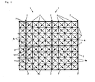
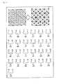
- Fig. 1 is an illustrative view depicting one example of a dot pattern of the present invention
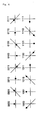
- Fig. 2 is an enlarged view showing one example of information dots of a dot pattern and bit representation of data defined therein;
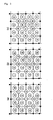
- Fig. 3 (a), Fig. 3 (b), and Fig. 3 (c) are illustrative views each depicting how key dots and information dots are laid out.
- the information input/output method using dot patterns is comprised of: recognition of a dot pattern 1; and means for outputting information and programs from this dot pattern 1.
- the dot pattern 1 is picked up as image data by means of a camera; a reference grid point dot 4 is first extracted, and then, the thus extracted dot is determined to be at a position of a virtual reference grid point 6; and a straight line connecting these virtual reference grid points 6 is defined as a reference grid line 7.
- the reference grid point dots 4 are not laid out at position of the virtual grid points 6 at which the dots should be, dots at the periphery of this virtual reference grid points 6 are extracted, and the extracted dots each are defined as a key dot 2 (rectangular parts at four corners of a block).
- a cross point of these oblique grid lines 8c is also defined as a virtual grid point 12 (second virtual grid point). Then, the dots at the periphery of this virtual grid point 12 are also retrieved, and then, the information dot 3 defined depending on the distance and direction from the virtual grid point 12 is extracted.
- the orientation of the block is determined depending on the direction from the virtual reference grid point 6 or virtual grid point 11 of a key dot 2.
- the information dot 3 in a block may be recognized while a vertical direction is defined as a forward direction.
- the information dot 3 in a block may be recognized while the direction in which the block has been rotated at 180 degrees around a block center is defined as a forward direction.
- the information dot in a block may be recognized while the direction in which the block has been rotated clockwise at an angle of 90 degrees around a block center is defined as a forward direction.
- the information dot 3 in a block may be recognized while the direction in which the block has been rotated counterclockwise at an angle of 90 degrees around a block center is defined as a forward direction.
- a central processing unit (CPU) of the optical reader means analyzes dots in the frame buffer, and then, decodes the numeric values defined by information dot 3 depending on the distance and direction from virtual grid points 11, 12 of information dots 3.
- these numeric values are crosschecked with information stored in the optical reader means or memory of a personal computer; and the voice, images, mobile images, and programs or the like corresponding to the xy coordinate or codes are read out, and then, are outputted from a voice/image output means or the like.
- the dot pattern 1 of the present invention in accordance with an algorithm for generating a dot code, in order to recognize information such as a voice, fine dots, i.e., the key dot 2, the information dot 3, and reference grid point dot 4 are arranged under a predetermined rule.
- a rectangular area such as a square or a rectangle, of a medium face such as a printed matter is defined as a block 1.
- straight lines in the vertical and horizontal directions configuring a frame of the block 1 each are defined as a reference grid line 7 (lines indicated by thick lines in Fig. 1 )
- virtual reference grid points 6 are provided at predetermined intervals on the reference grid line 7, and then, reference grid point dots 4 are laid out on the virtual reference grid points 6.
- straight lines connecting the virtual reference grid points 6 to each other and parallel to the reference grid line 7 are defined as grid lines 8a, 8b and a cross point between the grid lines 8a and 8b is defined as a virtual grid point 11 (first virtual grid point).
- an oblique grid line 8c connecting the virtual reference grid points 6 to each other in an oblique direction is set and a cross point between these oblique grid lines 8c is defined as a virtual grid point 12 (second virtual grid point).
- One or plurality of information dots 3 having a distance and a direction around the thus set grid point are laid out, respectively, to generate a dot pattern.
- this dot pattern 1 is picked up as image data by means of a camera, lens distortion of the camera or a distortion exerted at the time of oblique image pickup, paper expansion and contraction, medium surface curling, or printing can be corrected by means of the reference grid point dots 4.
- a correction function (X h Y n ) f (X' n Y' n ) is obtained for converting distorted four virtual grid points into an original square, information dots are corrected by the same function, and the vector of correct information dot 3 is obtained.
- the image data obtained by picking up this dot pattern 1 by means of a camera corrects the distortion caused by the camera, so that, when the image data on the dot pattern 1 is picked up by means of a general type camera having a lens with a high distortion rate mounted thereon as well, the image data can be precisely recognized. In addition, even if the camera is tilted relative to a face of the dot pattern 1, the dot pattern 1 can be precisely recognized.
- the key dot 2 serves as a dot laid out depending on a distance and a direction around one virtual grid point 11 that exists at a substantially central position of virtual grid points laid out in a rectangular shape.
- This key dot 2 serves as a representative point of the dot pattern 1 for one block representative of a group of information dots. For example, these dots are laid out at the positions shifted by 0.2 mm upwardly of a virtual grid point at the block center of the dot pattern 1. Therefore, in the case where the information dot 3 is defined by X, Y coordinate values from a virtual grid point, the position distant at a distance of 0.2 mm downwardly of the key dot 2 is defined as a virtual grid point (coordinate point). However, this numeric value 80.2 mm) can vary according to whether the block of the dot patterns 1 is large or small in size without being limitative thereto.
- the information dot 3 serves as a dot for recognizing a variety of information.
- the information dots 3 are laid out at the periphery thereof while the key dot is defined as a representative point and are laid out at end points expressed by means of a vector while the center surrounded by four virtual grid points 11 (first virtual grid points) is defined as a virtual grid point (second virtual grid point), and then, the defined grid point is defined as a start point.
- this information dot 3 is surrounded by means of virtual grid points 11, 12.
- the dots that are distant by 0.2 mm from the virtual point are laid out in eight directions while they are rotated clockwise by 45 degrees in order to provide the direction and length that are expressed by the vector, and then, three bits are-expressed.
- 3 bits x 16 48 bits can be expressed in a dot pattern 1 of one block.
- the dots layout is provided in the eight directions to express three bits
- the dot layout can be provided in 16 directions to express four bits and, of course, the dot layout can be variously changed.
- the diameter of the key dot 2, information dot, or reference grid point dot 4 be on the order of 0.1 mm in consideration of appearance, precision of printing relative to paper, camera resolution and optimal digitization.
- intervals of reference grid point dots 4 be on the order of 1 mm vertically and horizontally in consideration of incorrect recognition of a variety of dots 2, 3, 4. It is desirable that the distortion of the key dot 2 be on the order of 20% of the grid intervals.
- a gap between this information dot 3 and a virtual grid point 11, 12 be on the order of 15% to 30% of a distance between the virtual grid points 11 and 12 adjacent thereto.
- the reason therefor is set forth as follows. If the distance between the information dot and the virtual grid point 11, 12 is longer than this interval, dots are easily visually recognized as a large block, and the dot pattern 1 is eyesore. On the other hand, if the distance between the information dot 2 and the virtual grid point 11, 12 is shorter than the above interval, it becomes difficult to determine that the target dot is an information dot 3 having vector directivity around either of the virtual grid points 11, 12 adjacent thereto.
- Fig. 3 shows a sequential order of reading information dots 3 in a block, wherein the numbers circled in the figure denotes a layout area of the information dots laid out by virtual grid points 11, 12, respectively.
- Fig. 4 shows an example of an information dot 3 and bit representation of data defined therein and shows another aspect of the invention.
- a long dot (upper stage of Fig. 4 ) and a short dot (lower stage of Fig. 4 ) from the virtual grid points 11, 12 surrounded by the reference grip point dot 4 relative to the information dot 3
- four bits can be expressed.
- the long dot be on the order of 25% to 30% of a distance between the virtual grid points 11 and 12 adjacent thereto and that the short dot be on the order of 15% to 20% thereof.
- a central interval of the long and short be longer than the diameter of each of these dots.
- the information dot 3 surrounded by four virtual grid points 11, 12 be one dot in consideration of appearance.
- a large amount of information can be provided by assigning one bit, and then, expressing information dots 3 in plurality.
- information for 2 can be expressed by means of a information dot 3 and 2 128 is obtained by 16 information dots in one block.
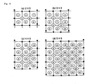
- Figs. 5 (a) to (f) each show an example of an information dot 3 and bit representation of data defined therein, wherein Fig. 5 (a) shows a case in which two dots are laid out; Fig. 5 (b) shows a case in which four dots are laid out; and Fig. 5 (c) to Fig. 5 (e) each show a case in which five dots are laid out; and Fig. 5 (f) shows a case in which seven dots are laid out.
- Figs. 6 (a) to (d) each show modification of a dot pattern, wherein Fig. 6 (a) shows a case in which eight information dots 3 are laid out in a block; Fig. 6 (b) shows a case in which 18 information dots are laid out therein; Fig. 6 (c) shows a case in which 13 information dots are laid out; and Fig. 6 (d) shows a case in which 41 information dots 3 are laid out.
- Each of the dot patterns 1 shown in Figs. 1 and 3 described previously also shows an example in which 25 information dots 3 are laid out in one block.
- these information dots 3 can be variously changed without being limitative thereto.
- eight information dots 3 may be laid out in one block ( Fig. 6 8a); 13 information dots may be laid out in one block ( Fig. 6 (b) ; 18 information dots 3 are laid out in one block ( Fig. 6 (c) ); or 41 information dots 3 are laid out in one block ( Fig. 6 (d) ).
- Fig. 7 is an illustrative view of a method for assigning "0" and "1" to the least significant bits and checking an information dot error.
- one information dot 3 is uniformly laid out and "0" and "1" are alternately assigned to the least significant bits so that they are used for checking an error, thereby making it possible to check an error of this information dot 3.
- information dots are generated alternately in the vertical, horizontal, and 45-degree tilt directions, making it possible to eliminate the regularity of a dot pattern.
- the information dots obtained by alternately assigning "0" and "1" to the least significant bits are always positioned in the vertical, horizontal, or 45-degree tilt direction around the virtual grid points 11, 12. Therefore, when the information dots 3 are positioned in a direction other than the horizontal or 45-degree tilt direction, these dots are determined as those displayed at their appropriate positions. In this way, an error inputted when the information dots 3 are shifted in a rotational direction around the virtual grid points 11, 12 can be reliably checked.
- the information dots 3 are determined as eight directions (45-degree intervals) and as long/short dots (refer to Fig. 4 ), if the least significant one bit is "0" or "1", among four bits, in the case where the above one bit is shifted to one of the positions of the adjacent three dots (concentric circle ⁇ two points at 45-degree rotation position + either one of long and short dots), it can be handled as an error and 100% error check can be made.
- Fig. 8 is an illustrative view depicting how information dots I 1 to I 16 are arranged in order to explain the security of information dots.
- a plurality of information dots are laid out in one column with a key dot 2 being a representative point and such one train is laid out in plurality of trains, and then, a difference in data between two trains adjacent to each other is handled as data on the information dot 3, whereby the information dots 3 each can be laid out so that regularity of the information dots 3 is eliminated.
- the security can be enhanced in order to disable visually reading the dot pattern 1 printed on a medium face.
- the information dots 3 are laid out in random, a pattern is eliminated, and the dot pattern can be made moderate.
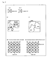
- Figs. 9 (a) to (d) show dummy dots, wherein Fig. 9 (a) is an illustrative view of dummy dots; Fig. 9 (b) shows one example of a printed matter; Fig. 9 (c) shows an area in a printed matter; and Fig. 9 (d) is an illustrative view depicting an example of laying out dot patterns that restrict the boundary of a mask by means of dummy dots.
- a dot is laid out at a central position (second virtual grid point) of four virtual grid points 11 (first virtual lattice points), and this dot is defined as a dummy dot 5 to which no information is imparted ( Fig. 9 (a) .
- This dummy dot 5 can be used for numeric data or areas in which X, Y coordinate values have been defined and the boundary between the areas, numeric data or an area in which the X, Y coordinate values are not defined.
- Fig. 9 (b) three types of patterns such as lesser bear, hippopotamus, or sun are printed on a printed matter, and then the areas corresponding to these three patterns are laid out as mask 1, mask 2, and mask 3, as shown in Fig. 9 (c) .
- Fig. 9 (d) the dummy dot 5 is laid out at the boundary of mask 1 and mask 2.
- the dummy dot 5 is used for the boundary, there is no need for defining all of the blocks of the corresponding positions as dummy dots 5, and it is sufficient if a minimum dot is defined as a dummy dot in order to indicate the boundary.
- a dummy dot is laid out in an area other than the masks, and an area in which no information is defined can be provided.
- the X, Y coordinate values are calculated at the positions of the key dot 2 that is a representative point of information, and thereafter, the coordinate values are compensated for by means of the increments of the X, Y coordinate values at the representative points adjacent to each other and a distance from an image pickup center to the key dot 2 on which the X, Y coordinate values have been calculated.
- the block of dot patterns 1 is picked up as image data by means of a camera
- information dots are sequentially read from the information dots that exist at the periphery of the image pickup center of the camera in an area in which identical data is defined in blocks or an area in which the X, Y coordinate values are defined, and then, information dots 3 equivalent to one block are read, whereby the dot pattern 1 is read in a minimum area from the image pickup center of the camera, and then, data at the image pickup central position is calculated.
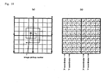
- Fig. 10 (b) is an illustrative view depicting a method for reading a dot pattern and calculating X, Y coordinate values.
- the X, Y coordinate values to be obtained are defined as X, Y coordinate values of a block having the camera image pickup center.
- the increment is defined as +1 in the X direction (right direction) and in the Y direction (upper direction) by block, there is a need for compensating for the information dots inputted from another block.
- K 8 K 7 K 6 K 5 i 16 i 15 i 14 i 13 i 12 i 11 i 10 i 9
- K 4 K 3 K 2 K 1 indicating the Y-coordinate value
- Other coordinate values K 16 to K 9 (i 32 to i 17 ) become identical in any block, and there is no need for compensation.
- 21 I 9 is a start point (camera image pickup center)
- X coordinate 11 K 8 21 K 7 • 21 K 6 • 21 K 5
- Y coordinate 12 K 4 • 12 K 3 • [ 22 K 2 • 22 K 1 + 1] - 1
- the dot pattern 1 When the dot pattern 1 is picked up as image data by means of the camera, if an error has occurred with the information dot 3, the closest information dot 3 equivalent to the information dot 3 is read, and then, the error is corrected, whereby the dot pattern 1 can be read in the minimum area from the image pickup center of the camera.
- a tablet or a digitizer that uses the XY coordinate and an input interface can be practiced.
- a transparent sheet on which the dot pattern 1 has been printed is superimposed on a target; an image is picked up by means of the camera; and then, the XY coordinate values of the dot pattern 1 are inputted.
- an image pickup element such as a CCD or a CMOS serving as optical image pickup means
- the image pickup data is expanded on a memory frame buffer.
- a central processing unit (CPU) of the optical image pickup means starts a search for the image data expanded on the frame buffer by means of a search program read out from the memory.
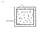
- reference grid point dots 4 configuring an outer frame of a block are linearly laid out at predetermined intervals, so that the central processing unit (CPU) determines whether or not a straight line is substantially obtained by connecting these linearly laid out dots to each other (refer to Fig. 11 ).
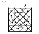
- the dots existing on the reference grid line 78 are laid out by predetermined length. At this time, if a distance between dots is equal to another distance, such dots are determined to be reference grid point dots 4. In the case where dots are laid out differently, these dots are determined to be key dots 2 ( Fig. 14 ).
- reference grid point dots 4 in the vertical and horizontal directions are connected to each other by means of straight lines (grid lines 8a, 8b), a cross point therebetween is defined as a virtual grid point 11 (first virtual grid point).
- virtual reference grid points 6 in the oblique direction are connected to each other, an oblique grid line 8c is defined, and a cross point between these oblique grid lines 8c is further defined as a virtual grid point 12 (second virtual grid point).
- an information dot 3 other than a block center is defined as a key dot 2 (in the case of Fig. 14 , where the position shifted in the upward direction by one virtual grid point from a block center is defined as the layout position of the key dot 2)
- the manner of imparting the information dot 3 in the corresponding rectangular area other than the key dot 2 is made different, whereby the key dot 2 and the information dot 3 can be discriminated from each other.
- the key dot 2 is laid out as a vector in only the vertical and horizontal directions from a virtual reference grid point 6 and if information is defined in an oblique direction in another rectangular area existing at a position turned by 90 degrees.
- length of a vector is defined as a predetermined length
- information may be defined by means of a vector different from another one in another rectangular area existing at a position turned by 90 degrees.
- information may be defined in any of the vertical, horizontal, and oblique directions.
- the dot pattern 1 of the present invention is printed on a printed matter such as a picture book or a text, and then, image data is picked by means of the camera. From the image data, a search is made for positions of information dots. From information on the positions, codes or XY coordinates are decoded. The voices, still pictures, motion pictures, characters, programs or the like corresponding to the codes or XY coordinates, are outputted from constituent elements such as a liquid crystal display device, s speaker, and a voice/image output terminal of equipment such as a personal computer, an information output device, a PDA (Personal Data Assistant), or a portable cellular phone.
- a liquid crystal display device such as a personal computer, an information output device, a PDA (Personal Data Assistant), or a portable cellular phone.
- PDA Personal Data Assistant
- information may be defined depending on a position that exists in the block of the information dot 3 while the distance and direction from the virtual grid points 11, 12 are arbitrarily limited by information dot 3.
- specification may be defined such that the distance and direction from the virtual grid points 11, 12 has been changed by type of industry using the dot pattern (by manufacturer, by service industrial field or by company using this dot pattern).
- the dot pattern of the present invention can be utilized discriminately by limited usage, making it possible to ensure the security against leakage such as information leakage or code system leakage between types of industries or between companies.
- the limited defined information can be provided so as to readable only by the optical reader means corresponding thereto.
- the present invention is not limitative to the embodiments of the invention described above. As long as a large amount of data is defined in a dot pattern by imparting different functions to dots 2, 3, 4 of a dot pattern 1, predetermined information or programs are outputted, and then, a variety of uses are enabled by recognizing directivity and speedily providing information, the present invention is not limitative to the embodiments described above. Of course, various modifications can occur without departing from the spirit of the present invention.
- the dots (information dots 3 or key dots 2), which are laid out around a cross point (virtual grid point 11) of grid lines 8a, 8b in the vertical and horizontal directions, may be shifted from the virtual grid point 11 onto the cross point.
- the dots at the cross point on an oblique grid line 8c may be laid out on the oblique grad line 8c similarly. In this way, dotes are always laid out on the grid lines 8a, 8b, 8c, whereby an algorithm of a reading program for making a search for the grid lines 8a, 8b, 8c can be simplified and reading efficiency can be remarkably improved.
- a dot pattern is picked up as image data by means of a camera, a reference grid point is first recognized and a key dot is extracted, directivity is recognized by means of the key dot, so that the direction can be used as a parameter.
- directivity is recognized by means of the key dot, so that the direction can be used as a parameter.
- a reference grid point dot is laid out in a dot pattern, so that, when this dot pattern is picked up as image data by means of the camera, a distortion can be corrected to a dot pattern picked up as an image due to a lens distortion of the camera or a distortion exerted at the time of oblique image pick, paper face expansion or contraction, medium surface curling, or printing.
- an error relative to a dot layout state can be checked, and security can be further enhanced.
Landscapes
- Engineering & Computer Science (AREA)
- Physics & Mathematics (AREA)
- Theoretical Computer Science (AREA)
- General Physics & Mathematics (AREA)
- General Health & Medical Sciences (AREA)
- Toxicology (AREA)
- Artificial Intelligence (AREA)
- Computer Vision & Pattern Recognition (AREA)
- Electromagnetism (AREA)
- Health & Medical Sciences (AREA)
- Editing Of Facsimile Originals (AREA)
- Image Processing (AREA)
- Printing Methods (AREA)
- Credit Cards Or The Like (AREA)
Claims (6)
- Procédé d'entrée/sortie d'informations utilisant des motifs de points, ledit procédé comprenant les étapes pour générer un motif de points (1) en agençant une pluralité de points fins sur une surface de support sur la base d'un l'algorithme de génération de code de points selon une règle prédéterminée, les points fins étant utilisés pour la reconnaissance de diverses informations, en lisant le motif de points (1) sous la forme d'informations d'image par un moyen de lecture optique, en convertissant le motif de points (1) en une valeur numérique, et en lisant et sortant des informations qui correspondent aux informations numériques provenant du moyen de stockage, caractérisé en ce que le motif de points est généré en :en définissant une zone rectangulaire d'un carré ou d'un rectangle sous la forme d'un bloc ;en définissant des lignes droites dans une direction verticale et une direction horizontale configurant une trame du bloc comme lignes de grille de référence (7) :en fournissant des points de grille de référence virtuels (6) en des intervalles prédéterminés sur les lignes de grille de référence (7) dans la direction verticale et la direction horizontale ;en plaçant des points de grille de référence (4) sur les points de grille de référence virtuels (6) ;en fournissant des lignes de grille (8a, 8b) en connectant les points de grille de référence virtuels (6) les uns aux autres, les lignes de grille étant des lignes droites parallèles aux lignes de grille de référence (7) ;en définissant un point d'intersection des lignes de grille comme point de grille virtuel (1), eten agençant un ou une pluralité de points d'informations (3), chacun de ceux-ci présentant une distance et une direction par référence avec le point de grille virtuel (11).
- Procédé d'entrée/sortie d'informations utilisant des motifs de points, selon la revendication 1, dans lequel dans le bloc, des lignes de grille obliques (8c), connectant les points de grille de référence virtuels (6) dans une direction oblique, sont en outre fournies ; un point d'intersection des lignes de grille obliques (8c) est défini comme point de grille virtuel supplémentaire (11), et un ou une pluralité de points d'informations (3) sont placés, chacun de ceux-ci présentant une distance et une direction par référence au point de grille virtuel supplémentaire.
- Procédé d'entrée/sortie d'informations utilisant des motifs de points, selon la revendication 1, dans lequel au niveau d'une frontière entre des zones définissant des informations différentes sur la surface de support, le motif de points (1) entraîne la reconnaissance de la frontière des zones en fonction de si oui ou non un point est agencé sur le point de grille virtuel (11), au lieu d'agencer le point d'informations (3).
- Procédé d'entrée/sortie d'informations utilisant des motifs de points, selon la revendication 1 ou 2, dans lequel le motif de points (1) présente une zone ne définissant aucune information sur la surface de support, et entraîne la reconnaissance de la zone ne définissant aucune information en fonction de si oui ou non un point est agencé sur le point de grille virtuel, au lieu d'agencer le point d'informations (3).
- Procédé d'entrée/sortie d'informations utilisant des motifs de points, selon la revendication 1 ou 2, dans lequel le motif de points définit des informations en fonction de si oui ou non un point est agencé sur le point de grille virtuel (11) comme le point d'information, en plus d'agencer le point d'information.
- Procédé d'entrée/sortie d'informations utilisant des motifs de points selon l'une quelconque des revendications 1 à 5, dans lequel un point clé (2) définissant l'orientation du bloc est placé en une position qui est décalée d'au moins un point de grille de référence virtuel sur la trame du bloc.
Priority Applications (1)
| Application Number | Priority Date | Filing Date | Title |
|---|---|---|---|
| EP12173995.7A EP2511853A3 (fr) | 2005-04-28 | 2005-04-28 | Motif de points |
Applications Claiming Priority (1)
| Application Number | Priority Date | Filing Date | Title |
|---|---|---|---|
| PCT/JP2005/008210 WO2006117869A1 (fr) | 2005-04-28 | 2005-04-28 | Méthode d’entrée/sortie d’informations utilisant un motif de points |
Related Child Applications (2)
| Application Number | Title | Priority Date | Filing Date |
|---|---|---|---|
| EP12173995.7A Division EP2511853A3 (fr) | 2005-04-28 | 2005-04-28 | Motif de points |
| EP12173995.7 Division-Into | 2012-06-28 |
Publications (3)
| Publication Number | Publication Date |
|---|---|
| EP1876552A1 EP1876552A1 (fr) | 2008-01-09 |
| EP1876552A4 EP1876552A4 (fr) | 2009-08-26 |
| EP1876552B1 true EP1876552B1 (fr) | 2012-10-31 |
Family
ID=37307676
Family Applications (2)
| Application Number | Title | Priority Date | Filing Date |
|---|---|---|---|
| EP12173995.7A Withdrawn EP2511853A3 (fr) | 2005-04-28 | 2005-04-28 | Motif de points |
| EP05737287A Revoked EP1876552B1 (fr) | 2005-04-28 | 2005-04-28 | Méthode d' entrée/sortie d' informations utilisant un motif de points |
Family Applications Before (1)
| Application Number | Title | Priority Date | Filing Date |
|---|---|---|---|
| EP12173995.7A Withdrawn EP2511853A3 (fr) | 2005-04-28 | 2005-04-28 | Motif de points |
Country Status (6)
| Country | Link |
|---|---|
| US (4) | US8031375B2 (fr) |
| EP (2) | EP2511853A3 (fr) |
| CN (1) | CN101167084B (fr) |
| AU (1) | AU2005331401B2 (fr) |
| CA (1) | CA2606135C (fr) |
| WO (1) | WO2006117869A1 (fr) |
Families Citing this family (31)
| Publication number | Priority date | Publication date | Assignee | Title |
|---|---|---|---|---|
| EP1959376B1 (fr) | 2002-09-26 | 2016-04-06 | Kenji Yoshida | Dispositif, procédé et programme traitant d'informations pour la lecture d'un code à points |
| WO2006070458A1 (fr) * | 2004-12-28 | 2006-07-06 | Kenji Yoshida | Procede d'entree/sortie d'informations utilisant une image tramee |
| EP2511853A3 (fr) * | 2005-04-28 | 2013-09-11 | YOSHIDA, Kenji | Motif de points |
| JP3771252B1 (ja) | 2005-07-01 | 2006-04-26 | 健治 吉田 | ドットパターン |
| CN101379460B (zh) * | 2006-01-31 | 2011-09-28 | 吉田健治 | 图像处理方法 |
| TWI370413B (en) * | 2006-04-14 | 2012-08-11 | Sonix Technology Co Ltd | Graphical indicator |
| JP4448156B2 (ja) | 2007-07-05 | 2010-04-07 | キヤノン株式会社 | 装置、方法およびプログラム |
| WO2009057314A1 (fr) * | 2007-10-30 | 2009-05-07 | Kenji Yoshida | Motif de code |
| AU2007254595B2 (en) * | 2007-12-20 | 2011-04-07 | Canon Kabushiki Kaisha | Constellation detection |
| DE102008017168A1 (de) * | 2008-04-02 | 2009-10-08 | Crossmedia Solution Gmbh & Co. Kg | Verfahren zum Speichern und Auslesen von Daten |
| TWI391862B (zh) * | 2008-06-06 | 2013-04-01 | Elan Microelectronics Corp | A two-dimensional dot code, a decoding apparatus, and a method thereof |
| TWI444906B (zh) * | 2008-06-17 | 2014-07-11 | Elan Microelectronics Corp | Method of Decoding Two - dimensional |
| TWI397013B (zh) * | 2008-09-26 | 2013-05-21 | Elan Microelectronics Corp | The dot code pattern and the dot code group pattern and the image processing circuit of the density coding type |
| TWI393055B (zh) * | 2008-09-26 | 2013-04-11 | Elan Microelectronics Corp | A dot pattern having a cross-shaped positioning pattern, and an image processing device for processing the dot pattern |
| JP2011010161A (ja) * | 2009-06-29 | 2011-01-13 | Canon Inc | 画像形成装置、画像形成方法、プログラム |
| JP5550481B2 (ja) * | 2009-08-12 | 2014-07-16 | キヤノン株式会社 | 画像形成装置、画像形成方法、及びプログラム |
| JP5604761B2 (ja) * | 2009-11-11 | 2014-10-15 | 健治 吉田 | 印刷媒体、情報処理方法、情報処理装置 |
| JP5489118B2 (ja) * | 2010-01-28 | 2014-05-14 | 健治 吉田 | 入出力装置、情報入出力システム |
| CN101794404A (zh) * | 2010-03-09 | 2010-08-04 | 刘建生 | 隐形二维码的编码与识读方法 |
| TWI439943B (zh) * | 2010-04-27 | 2014-06-01 | Shou Te Wei | 點圖像編碼結構、其解碼方法與電子裝置 |
| JP5744425B2 (ja) | 2010-06-25 | 2015-07-08 | キヤノン株式会社 | 出力禁止情報を抽出可能な装置、その制御方法、プログラム |
| JP5688516B2 (ja) * | 2012-01-21 | 2015-03-25 | 松翰科技股▲ふん▼有限公司 | ドットコードを用いたデータ入力/出力方法 |
| KR101453467B1 (ko) * | 2012-06-05 | 2014-10-22 | (주)펜제너레이션스 | 광학필름 및 이를 이용한 전자펜 시스템 |
| US9131076B2 (en) | 2013-02-05 | 2015-09-08 | Kelvin Patrick LeBeaux | System, method and computer program product for facilitating optical data transfer to a mobile device |
| EP3149096B1 (fr) * | 2014-05-30 | 2020-06-24 | Henkel AG & Co. KGaA | Procédé et appareil pour enlever un module d'affichage collé au moyen d'un adhésif liquide optiquement transparent |
| CN105335740B (zh) | 2015-10-19 | 2019-01-11 | 松翰科技股份有限公司 | 图像指标的读取方法、指标结构以及其电子装置 |
| JP2019012424A (ja) * | 2017-06-30 | 2019-01-24 | ブラザー工業株式会社 | 画像処理装置、および、コンピュータプログラム |
| EP3557481B1 (fr) | 2018-04-20 | 2023-02-22 | Nxp B.V. | Procédé pour fournir un motif de code |
| NL2024079B1 (en) * | 2019-10-22 | 2021-07-13 | Filimade Holding B V | Method of identifying an item, waste separation and item comprising a dot code |
| CN114861847B (zh) * | 2021-01-20 | 2023-04-14 | 上海驰亚信息技术有限公司 | 点阵码构建方法、生成读取方法及终端、点阵码系统 |
| CN115388708B (zh) | 2021-05-21 | 2024-07-09 | 信泰光学(深圳)有限公司 | 瞄准补正机构 |
Family Cites Families (92)
| Publication number | Priority date | Publication date | Assignee | Title |
|---|---|---|---|---|
| US4263504A (en) | 1979-08-01 | 1981-04-21 | Ncr Corporation | High density matrix code |
| US4604065A (en) | 1982-10-25 | 1986-08-05 | Price/Stern/Sloan Publishers, Inc. | Teaching or amusement apparatus |
| JPS6165213A (ja) | 1984-09-06 | 1986-04-03 | Canon Inc | オ−トフオ−カス用光学系 |
| US4627819A (en) | 1985-01-23 | 1986-12-09 | Price/Stern/Sloan Publishers, Inc. | Teaching or amusement apparatus |
| US4924078A (en) | 1987-11-25 | 1990-05-08 | Sant Anselmo Carl | Identification symbol, system and method |
| US4939354A (en) | 1988-05-05 | 1990-07-03 | Datacode International, Inc. | Dynamically variable machine readable binary code and method for reading and producing thereof |
| US5124536A (en) | 1988-05-05 | 1992-06-23 | International Data Matrix, Inc. | Dynamically variable machine readable binary code and method for reading and producing thereof |
| US5042079A (en) | 1988-08-12 | 1991-08-20 | Casio Computer Co., Ltd. | Method of recording/reproducing data of mesh pattern, and apparatus therefor |
| US5591957A (en) | 1988-08-12 | 1997-01-07 | Casio Computer Co., Ltd. | Apparatus for reading mesh pattern image data having bars along upper and lower sides of mesh pattern and a boundary line between horizontally adjacent dark and light area of mesh pattern |
| US5051736A (en) | 1989-06-28 | 1991-09-24 | International Business Machines Corporation | Optical stylus and passive digitizing tablet data input system |
| US5128528A (en) | 1990-10-15 | 1992-07-07 | Dittler Brothers, Inc. | Matrix encoding devices and methods |
| FR2684214B1 (fr) | 1991-11-22 | 1997-04-04 | Sepro Robotique | Carte a indexation pour systeme d'information geographique et systeme en comportant application. |
| US5852434A (en) | 1992-04-03 | 1998-12-22 | Sekendur; Oral F. | Absolute optical position determination |
| JPH10187907A (ja) | 1992-09-28 | 1998-07-21 | Olympus Optical Co Ltd | ドットコード |
| EP0996083B1 (fr) | 1992-09-28 | 2003-03-26 | Olympus Optical Co., Ltd. | Système de reproduction d'information pour la lecture de code à points d'un support d'enregistrement |
| US5416312A (en) | 1992-11-20 | 1995-05-16 | Cherloc | Document bearing an image or a text and provided with an indexing frame, and associated document analysis system |
| RU2126598C1 (ru) | 1993-11-16 | 1999-02-20 | Кузнецов Юрий Вениаминович | Способ и устройство адаптивного растрирования полутоновых изображений |
| JP3277052B2 (ja) | 1993-11-19 | 2002-04-22 | シャープ株式会社 | 座標入力装置、および座標入力方法 |
| JPH07178257A (ja) | 1993-12-24 | 1995-07-18 | Casio Comput Co Ltd | 音声出力装置 |
| JPH07296387A (ja) | 1994-04-22 | 1995-11-10 | Olympus Optical Co Ltd | 情報記録媒体 |
| JPH0837567A (ja) | 1994-07-26 | 1996-02-06 | Olympus Optical Co Ltd | 情報記録媒体及び情報再生装置 |
| JP2912831B2 (ja) | 1994-10-05 | 1999-06-28 | オリンパス光学工業株式会社 | 情報記録媒体及び情報再生装置 |
| JP3639328B2 (ja) | 1994-10-14 | 2005-04-20 | オリンパス株式会社 | 情報記録媒体、2次元コード、情報再生システム、及び情報再生方法 |
| US5661506A (en) | 1994-11-10 | 1997-08-26 | Sia Technology Corporation | Pen and paper information recording system using an imaging pen |
| JP2952170B2 (ja) | 1994-12-16 | 1999-09-20 | オリンパス光学工業株式会社 | 情報再生システム |
| JP3523710B2 (ja) | 1995-04-04 | 2004-04-26 | オリンパス株式会社 | 情報再生システム、記録媒体、記録装置及び記録方法 |
| GB9507098D0 (en) | 1995-04-06 | 1995-05-31 | Rolls Royce Plc | Process and apparatus for reading a dot matrix code marking of an article |
| JPH0944591A (ja) | 1995-08-03 | 1997-02-14 | Olympus Optical Co Ltd | コードシート及び情報再生装置 |
| JPH09114951A (ja) | 1995-10-23 | 1997-05-02 | Olympus Optical Co Ltd | 情報記録媒体 |
| JPH09185488A (ja) | 1995-12-27 | 1997-07-15 | Tetsuya Fuchiguchi | マルチメディア人形装置 |
| JP3956419B2 (ja) | 1997-03-06 | 2007-08-08 | 凸版印刷株式会社 | Idカード作成方法、idカードおよびidカードの情報読取方法 |
| JPH10326331A (ja) | 1997-03-24 | 1998-12-08 | Olympus Optical Co Ltd | ドットコードを有する記録媒体及びコード読取装置 |
| JPH10326323A (ja) | 1997-03-24 | 1998-12-08 | Olympus Optical Co Ltd | コードパターンイメージ記録装置 |
| US6012961A (en) | 1997-05-14 | 2000-01-11 | Design Lab, Llc | Electronic toy including a reprogrammable data storage device |
| JPH10320497A (ja) | 1997-05-16 | 1998-12-04 | Olympus Optical Co Ltd | コード読取記録装置 |
| JP3953144B2 (ja) | 1997-07-16 | 2007-08-08 | オリンパス株式会社 | コードイメージ品質検査装置 |
| EP0921675B1 (fr) | 1997-12-03 | 2006-07-05 | Kabushiki Kaisha Toshiba | Procédé de traitement d'information d'image et procédé d'empêchement de la falsification de certificats ou même |
| JP3959817B2 (ja) | 1998-01-07 | 2007-08-15 | 富士ゼロックス株式会社 | 画像形成装置 |
| JPH11219405A (ja) | 1998-02-02 | 1999-08-10 | Olympus Optical Co Ltd | 情報再生システム |
| WO1999050787A1 (fr) | 1998-04-01 | 1999-10-07 | Xerox Corporation | Fonctions interreseaux par liaison de documents imprimes et de documents electroniques |
| JP3458737B2 (ja) | 1998-11-27 | 2003-10-20 | 株式会社デンソー | 2次元コードの読取方法及び記録媒体 |
| JP2000285225A (ja) | 1999-03-30 | 2000-10-13 | Kiyoyuki Horii | コンピュータによる画像処理方法 |
| RU2166207C2 (ru) | 1999-04-08 | 2001-04-27 | Закрытое акционерное общество "Аби Программное обеспечение" | Способ использования вспомогательных массивов данных в процессе преобразования и/или верификации компьютерных кодов, выполненных в виде символов, и соответствующих им фрагментов изображения |
| GB2349836A (en) | 1999-04-23 | 2000-11-15 | Tri State | Talking doll with bar-code optical reader |
| JP2000325668A (ja) | 1999-05-14 | 2000-11-28 | T Shot:Kk | 反応式トーキング玩具システム |
| AUPQ363299A0 (en) | 1999-10-25 | 1999-11-18 | Silverbrook Research Pty Ltd | Paper based information inter face |
| US7055739B1 (en) | 1999-05-25 | 2006-06-06 | Silverbrook Research Pty Ltd | Identity-coded surface with reference points |
| US6987573B1 (en) | 1999-05-25 | 2006-01-17 | Silverbrook Research Pty Ltd | Interface surface printer |
| EP1188142A1 (fr) | 1999-05-28 | 2002-03-20 | Anoto AB | Enregistrement d'informations |
| JP3764100B2 (ja) | 1999-05-28 | 2006-04-05 | アノト アイ ピー リック エイチ ビー | カレンダー帳 |
| US6502756B1 (en) | 1999-05-28 | 2003-01-07 | Anoto Ab | Recording of information |
| SE516522C2 (sv) | 1999-05-28 | 2002-01-22 | Anoto Ab | Positionsbestämning |
| JP2001052104A (ja) * | 1999-08-05 | 2001-02-23 | Olympus Optical Co Ltd | データ記録方法及びデータ再生方法、並びにデータ記録媒体 |
| SE0000939L (sv) | 2000-02-18 | 2001-08-19 | Anoto Ab | Inenhetsarrangemang |
| EP1087330A3 (fr) | 1999-09-21 | 2002-04-10 | Omron Corporation | Code bidimensionnel par points et lecteur pour cela |
| SE517445C2 (sv) | 1999-10-01 | 2002-06-04 | Anoto Ab | Positionsbestämning på en yta försedd med ett positionskodningsmönster |
| WO2001048678A1 (fr) | 1999-12-23 | 2001-07-05 | Anoto Ab | Gestion d'information repartie |
| US6244764B1 (en) | 2000-01-21 | 2001-06-12 | Robotic Vision Systems, Inc. | Method for data matrix print quality verification |
| US6615109B1 (en) | 2000-02-10 | 2003-09-02 | Sony Corporation | System and method for generating an action of an automatic apparatus |
| US6586688B2 (en) | 2000-04-05 | 2003-07-01 | Anoto Ab | Information-related devices and methods |
| US7050653B2 (en) | 2000-04-05 | 2006-05-23 | Anoto Ab | Identification of virtual raster pattern |
| JP2001287330A (ja) | 2000-04-10 | 2001-10-16 | Olympus Optical Co Ltd | 光学的に読み取り可能なドットのイメージデータ作成方法及びイメージデータ作成装置、並びに記録媒体 |
| JP2001318926A (ja) | 2000-05-11 | 2001-11-16 | Yazaki Corp | 情報管理装置及び該装置を利用する情報管理システム |
| JP2002041199A (ja) | 2000-05-15 | 2002-02-08 | Pasukaru:Kk | ショートカットシンボルを用いたコンピュータ装置の操作処理方法、ショートカット処理システム |
| JP2001334012A (ja) | 2000-05-29 | 2001-12-04 | Creatures Inc | 遊戯カードを使用したゲームシステム、それに用いられる遊戯カード、及びそれに用いられるゲーム情報記憶媒体 |
| JP3837999B2 (ja) | 2000-06-05 | 2006-10-25 | 富士ゼロックス株式会社 | 画像生成方法および画像生成装置 |
| JP2002002024A (ja) | 2000-06-26 | 2002-01-08 | Olympus Optical Co Ltd | コード印字方法、コード印字装置、及び記録媒体 |
| JP4567860B2 (ja) | 2000-09-12 | 2010-10-20 | 任天堂株式会社 | コード読取装置、記録媒体、電子機器、データ送受信システム、及びデータ送受信方法 |
| WO2002023464A1 (fr) | 2000-09-12 | 2002-03-21 | Omron Corporation | Code a points et lecteur de code a points |
| JP2002205291A (ja) | 2000-10-23 | 2002-07-23 | Sony Corp | 脚式ロボット及び脚式ロボットの行動制御方法、並びに記憶媒体 |
| JP2002149331A (ja) | 2000-11-15 | 2002-05-24 | Canon Inc | 座標板、座標入力装置、座標入出力装置 |
| US6633008B2 (en) * | 2001-02-27 | 2003-10-14 | Weigh-Tronix, Inc. | Electronic force sensing shock resistant load cell |
| JP4763905B2 (ja) | 2001-03-06 | 2011-08-31 | オリンパス株式会社 | 符号化画像読取装置 |
| US7649637B2 (en) | 2001-04-05 | 2010-01-19 | Anoto Ab | Method for printing a global position-coding pattern |
| US6732927B2 (en) | 2001-06-26 | 2004-05-11 | Anoto Ab | Method and device for data decoding |
| SE520682C2 (sv) | 2001-12-06 | 2003-08-12 | Anoto Ab | Rekonstruering av ett virtuellt raster |
| TWI235926B (en) | 2002-01-11 | 2005-07-11 | Sonix Technology Co Ltd | A method for producing indicators and processing system, coordinate positioning system and electronic book system utilizing the indicators |
| EP1959376B1 (fr) * | 2002-09-26 | 2016-04-06 | Kenji Yoshida | Dispositif, procédé et programme traitant d'informations pour la lecture d'un code à points |
| SE0203853D0 (sv) | 2002-12-23 | 2002-12-23 | Anoto Ab | Informationskod |
| ES2309304T3 (es) * | 2003-03-17 | 2008-12-16 | Kenji Yoshida | Procedimiento de entrada/salida de informaciones utilizando una plantilla de puntos. |
| JP3902163B2 (ja) | 2003-07-11 | 2007-04-04 | 大日本印刷株式会社 | 関連帳票判定システム、電子ペン及びプログラム |
| JP4200106B2 (ja) | 2003-07-15 | 2008-12-24 | 株式会社リコー | 画像処理装置、画像処理方法、コンピュータプログラム、及びコンピュータプログラムを記憶する記憶媒体 |
| JP3766678B2 (ja) * | 2003-12-25 | 2006-04-12 | 健治 吉田 | ドットパターンを用いた情報入出力方法 |
| WO2006070458A1 (fr) | 2004-12-28 | 2006-07-06 | Kenji Yoshida | Procede d'entree/sortie d'informations utilisant une image tramee |
| US8189923B2 (en) | 2005-04-15 | 2012-05-29 | Kenji Yoshida | Information input output method using a dot pattern |
| EP2511853A3 (fr) * | 2005-04-28 | 2013-09-11 | YOSHIDA, Kenji | Motif de points |
| JP3771252B1 (ja) | 2005-07-01 | 2006-04-26 | 健治 吉田 | ドットパターン |
| JP4810918B2 (ja) | 2005-08-01 | 2011-11-09 | 富士ゼロックス株式会社 | コードパターン画像生成装置及び方法、コードパターン画像読取装置及び方法、及びコードパターン画像媒体 |
| AU2006252254B2 (en) | 2006-12-22 | 2009-03-05 | Canon Kabushiki Kaisha | Multiple barcode detection |
| AU2006252239B2 (en) | 2006-12-22 | 2010-04-01 | Canon Kabushiki Kaisha | Barcode pattern |
| US20080252916A1 (en) | 2007-04-13 | 2008-10-16 | Etoms Electronics Corp. | Information reproduction method and device using dot pattern and dot pattern thereof |
| TWI391862B (zh) | 2008-06-06 | 2013-04-01 | Elan Microelectronics Corp | A two-dimensional dot code, a decoding apparatus, and a method thereof |
-
2005
- 2005-04-28 EP EP12173995.7A patent/EP2511853A3/fr not_active Withdrawn
- 2005-04-28 EP EP05737287A patent/EP1876552B1/fr not_active Revoked
- 2005-04-28 US US11/912,597 patent/US8031375B2/en not_active Expired - Fee Related
- 2005-04-28 CA CA2606135A patent/CA2606135C/fr not_active Expired - Fee Related
- 2005-04-28 WO PCT/JP2005/008210 patent/WO2006117869A1/fr not_active Ceased
- 2005-04-28 AU AU2005331401A patent/AU2005331401B2/en not_active Ceased
- 2005-04-28 CN CN200580049625.6A patent/CN101167084B/zh not_active Ceased
-
2011
- 2011-10-03 US US13/251,903 patent/US8253982B2/en not_active Expired - Fee Related
-
2012
- 2012-08-20 US US13/589,767 patent/US8553284B2/en not_active Expired - Fee Related
-
2013
- 2013-10-07 US US14/047,759 patent/US9582701B2/en not_active Expired - Fee Related
Also Published As
| Publication number | Publication date |
|---|---|
| CN101167084B (zh) | 2010-05-12 |
| HK1115463A1 (zh) | 2008-11-28 |
| US20130050724A1 (en) | 2013-02-28 |
| CA2606135A1 (fr) | 2006-11-09 |
| AU2005331401B2 (en) | 2012-07-12 |
| CA2606135C (fr) | 2015-06-30 |
| EP2511853A2 (fr) | 2012-10-17 |
| US8253982B2 (en) | 2012-08-28 |
| US20140029062A1 (en) | 2014-01-30 |
| US9582701B2 (en) | 2017-02-28 |
| JPWO2006117869A1 (ja) | 2008-12-18 |
| US20090066977A1 (en) | 2009-03-12 |
| US8031375B2 (en) | 2011-10-04 |
| US20120074235A1 (en) | 2012-03-29 |
| EP1876552A1 (fr) | 2008-01-09 |
| AU2005331401A1 (en) | 2006-11-09 |
| EP1876552A4 (fr) | 2009-08-26 |
| CN101167084A (zh) | 2008-04-23 |
| US8553284B2 (en) | 2013-10-08 |
| WO2006117869A1 (fr) | 2006-11-09 |
| EP2511853A3 (fr) | 2013-09-11 |
| JP3858051B1 (ja) | 2006-12-13 |
Similar Documents
| Publication | Publication Date | Title |
|---|---|---|
| EP1876552B1 (fr) | Méthode d' entrée/sortie d' informations utilisant un motif de points | |
| JP5848464B2 (ja) | 二次元コード、二次元コードの作成システムおよび解析プログラム | |
| JP3706385B2 (ja) | ドットパターンを用いた情報入出力方法 | |
| KR100935345B1 (ko) | 도트 패턴 | |
| US20130020386A1 (en) | Information input output method using dot pattern | |
| JP5791826B2 (ja) | 二次元コード | |
| HK1200948A1 (en) | Code pattern | |
| CN101167090A (zh) | 使用了点图形的信息输入输出方法 | |
| KR100591300B1 (ko) | 도트 패턴을 이용한 정보 입출력 방법 | |
| AU2012241078A1 (en) | Printed Material Printed with a Dot Pattern | |
| AU2016200846A1 (en) | Printed Material Printed with a Dot Pattern | |
| JP3858051B6 (ja) | ドットパターンを用いた情報入出力方法 | |
| KR20060023602A (ko) | 도트 패턴을 이용한 정보 입출력 방법 | |
| RU2381552C2 (ru) | Способ ввода/вывода информации с использованием образа с точечными элементами | |
| CN101872411A (zh) | 微小码阵列的编码方法、解码方法以及编码和解码方法 | |
| HK1113419B (en) | Information input/output method using dot pattern |
Legal Events
| Date | Code | Title | Description |
|---|---|---|---|
| PUAI | Public reference made under article 153(3) epc to a published international application that has entered the european phase |
Free format text: ORIGINAL CODE: 0009012 |
|
| 17P | Request for examination filed |
Effective date: 20071108 |
|
| AK | Designated contracting states |
Kind code of ref document: A1 Designated state(s): AT BE BG CH CY CZ DE DK EE ES FI FR GB GR HU IE IS IT LI LT LU MC NL PL PT RO SE SI SK TR |
|
| DAX | Request for extension of the european patent (deleted) | ||
| A4 | Supplementary search report drawn up and despatched |
Effective date: 20090727 |
|
| 17Q | First examination report despatched |
Effective date: 20100618 |
|
| REG | Reference to a national code |
Ref country code: DE Ref legal event code: R079 Ref document number: 602005036802 Country of ref document: DE Free format text: PREVIOUS MAIN CLASS: G06K0007100000 Ipc: G06K0019060000 |
|
| GRAP | Despatch of communication of intention to grant a patent |
Free format text: ORIGINAL CODE: EPIDOSNIGR1 |
|
| RIC1 | Information provided on ipc code assigned before grant |
Ipc: G06K 19/06 20060101AFI20120315BHEP |
|
| GRAS | Grant fee paid |
Free format text: ORIGINAL CODE: EPIDOSNIGR3 |
|
| GRAA | (expected) grant |
Free format text: ORIGINAL CODE: 0009210 |
|
| AK | Designated contracting states |
Kind code of ref document: B1 Designated state(s): AT BE BG CH CY CZ DE DK EE ES FI FR GB GR HU IE IS IT LI LT LU MC NL PL PT RO SE SI SK TR |
|
| REG | Reference to a national code |
Ref country code: GB Ref legal event code: FG4D Ref country code: CH Ref legal event code: EP |
|
| REG | Reference to a national code |
Ref country code: AT Ref legal event code: REF Ref document number: 582365 Country of ref document: AT Kind code of ref document: T Effective date: 20121115 |
|
| REG | Reference to a national code |
Ref country code: IE Ref legal event code: FG4D |
|
| REG | Reference to a national code |
Ref country code: DE Ref legal event code: R096 Ref document number: 602005036802 Country of ref document: DE Effective date: 20121227 |
|
| REG | Reference to a national code |
Ref country code: AT Ref legal event code: MK05 Ref document number: 582365 Country of ref document: AT Kind code of ref document: T Effective date: 20121031 |
|
| REG | Reference to a national code |
Ref country code: LT Ref legal event code: MG4D |
|
| REG | Reference to a national code |
Ref country code: NL Ref legal event code: VDEP Effective date: 20121031 |
|
| PG25 | Lapsed in a contracting state [announced via postgrant information from national office to epo] |
Ref country code: FI Free format text: LAPSE BECAUSE OF FAILURE TO SUBMIT A TRANSLATION OF THE DESCRIPTION OR TO PAY THE FEE WITHIN THE PRESCRIBED TIME-LIMIT Effective date: 20121031 Ref country code: LT Free format text: LAPSE BECAUSE OF FAILURE TO SUBMIT A TRANSLATION OF THE DESCRIPTION OR TO PAY THE FEE WITHIN THE PRESCRIBED TIME-LIMIT Effective date: 20121031 Ref country code: SE Free format text: LAPSE BECAUSE OF FAILURE TO SUBMIT A TRANSLATION OF THE DESCRIPTION OR TO PAY THE FEE WITHIN THE PRESCRIBED TIME-LIMIT Effective date: 20121031 Ref country code: IS Free format text: LAPSE BECAUSE OF FAILURE TO SUBMIT A TRANSLATION OF THE DESCRIPTION OR TO PAY THE FEE WITHIN THE PRESCRIBED TIME-LIMIT Effective date: 20130228 Ref country code: ES Free format text: LAPSE BECAUSE OF FAILURE TO SUBMIT A TRANSLATION OF THE DESCRIPTION OR TO PAY THE FEE WITHIN THE PRESCRIBED TIME-LIMIT Effective date: 20130211 Ref country code: NL Free format text: LAPSE BECAUSE OF FAILURE TO SUBMIT A TRANSLATION OF THE DESCRIPTION OR TO PAY THE FEE WITHIN THE PRESCRIBED TIME-LIMIT Effective date: 20121031 |
|
| PG25 | Lapsed in a contracting state [announced via postgrant information from national office to epo] |
Ref country code: PL Free format text: LAPSE BECAUSE OF FAILURE TO SUBMIT A TRANSLATION OF THE DESCRIPTION OR TO PAY THE FEE WITHIN THE PRESCRIBED TIME-LIMIT Effective date: 20121031 Ref country code: SI Free format text: LAPSE BECAUSE OF FAILURE TO SUBMIT A TRANSLATION OF THE DESCRIPTION OR TO PAY THE FEE WITHIN THE PRESCRIBED TIME-LIMIT Effective date: 20121031 Ref country code: GR Free format text: LAPSE BECAUSE OF FAILURE TO SUBMIT A TRANSLATION OF THE DESCRIPTION OR TO PAY THE FEE WITHIN THE PRESCRIBED TIME-LIMIT Effective date: 20130201 Ref country code: BE Free format text: LAPSE BECAUSE OF FAILURE TO SUBMIT A TRANSLATION OF THE DESCRIPTION OR TO PAY THE FEE WITHIN THE PRESCRIBED TIME-LIMIT Effective date: 20121031 Ref country code: PT Free format text: LAPSE BECAUSE OF FAILURE TO SUBMIT A TRANSLATION OF THE DESCRIPTION OR TO PAY THE FEE WITHIN THE PRESCRIBED TIME-LIMIT Effective date: 20130228 Ref country code: CY Free format text: LAPSE BECAUSE OF FAILURE TO SUBMIT A TRANSLATION OF THE DESCRIPTION OR TO PAY THE FEE WITHIN THE PRESCRIBED TIME-LIMIT Effective date: 20121031 |
|
| PG25 | Lapsed in a contracting state [announced via postgrant information from national office to epo] |
Ref country code: AT Free format text: LAPSE BECAUSE OF FAILURE TO SUBMIT A TRANSLATION OF THE DESCRIPTION OR TO PAY THE FEE WITHIN THE PRESCRIBED TIME-LIMIT Effective date: 20121031 |
|
| PG25 | Lapsed in a contracting state [announced via postgrant information from national office to epo] |
Ref country code: BG Free format text: LAPSE BECAUSE OF FAILURE TO SUBMIT A TRANSLATION OF THE DESCRIPTION OR TO PAY THE FEE WITHIN THE PRESCRIBED TIME-LIMIT Effective date: 20130131 Ref country code: SK Free format text: LAPSE BECAUSE OF FAILURE TO SUBMIT A TRANSLATION OF THE DESCRIPTION OR TO PAY THE FEE WITHIN THE PRESCRIBED TIME-LIMIT Effective date: 20121031 Ref country code: EE Free format text: LAPSE BECAUSE OF FAILURE TO SUBMIT A TRANSLATION OF THE DESCRIPTION OR TO PAY THE FEE WITHIN THE PRESCRIBED TIME-LIMIT Effective date: 20121031 Ref country code: CZ Free format text: LAPSE BECAUSE OF FAILURE TO SUBMIT A TRANSLATION OF THE DESCRIPTION OR TO PAY THE FEE WITHIN THE PRESCRIBED TIME-LIMIT Effective date: 20121031 Ref country code: DK Free format text: LAPSE BECAUSE OF FAILURE TO SUBMIT A TRANSLATION OF THE DESCRIPTION OR TO PAY THE FEE WITHIN THE PRESCRIBED TIME-LIMIT Effective date: 20121031 |
|
| PLBI | Opposition filed |
Free format text: ORIGINAL CODE: 0009260 |
|
| PG25 | Lapsed in a contracting state [announced via postgrant information from national office to epo] |
Ref country code: RO Free format text: LAPSE BECAUSE OF FAILURE TO SUBMIT A TRANSLATION OF THE DESCRIPTION OR TO PAY THE FEE WITHIN THE PRESCRIBED TIME-LIMIT Effective date: 20121031 |
|
| PLAX | Notice of opposition and request to file observation + time limit sent |
Free format text: ORIGINAL CODE: EPIDOSNOBS2 |
|
| 26 | Opposition filed |
Opponent name: SONIX TECHNOLOGY CO., LTD. Effective date: 20130731 |
|
| REG | Reference to a national code |
Ref country code: DE Ref legal event code: R026 Ref document number: 602005036802 Country of ref document: DE Effective date: 20130731 |
|
| PG25 | Lapsed in a contracting state [announced via postgrant information from national office to epo] |
Ref country code: MC Free format text: LAPSE BECAUSE OF FAILURE TO SUBMIT A TRANSLATION OF THE DESCRIPTION OR TO PAY THE FEE WITHIN THE PRESCRIBED TIME-LIMIT Effective date: 20121031 |
|
| REG | Reference to a national code |
Ref country code: CH Ref legal event code: PL |
|
| PLBB | Reply of patent proprietor to notice(s) of opposition received |
Free format text: ORIGINAL CODE: EPIDOSNOBS3 |
|
| REG | Reference to a national code |
Ref country code: IE Ref legal event code: MM4A |
|
| PG25 | Lapsed in a contracting state [announced via postgrant information from national office to epo] |
Ref country code: LI Free format text: LAPSE BECAUSE OF NON-PAYMENT OF DUE FEES Effective date: 20130430 Ref country code: CH Free format text: LAPSE BECAUSE OF NON-PAYMENT OF DUE FEES Effective date: 20130430 |
|
| PLAB | Opposition data, opponent's data or that of the opponent's representative modified |
Free format text: ORIGINAL CODE: 0009299OPPO |
|
| R26 | Opposition filed (corrected) |
Opponent name: SONIX TECHNOLOGY CO., LTD. Effective date: 20130731 |
|
| PG25 | Lapsed in a contracting state [announced via postgrant information from national office to epo] |
Ref country code: IE Free format text: LAPSE BECAUSE OF NON-PAYMENT OF DUE FEES Effective date: 20130428 |
|
| REG | Reference to a national code |
Ref country code: FR Ref legal event code: PLFP Year of fee payment: 11 |
|
| RDAF | Communication despatched that patent is revoked |
Free format text: ORIGINAL CODE: EPIDOSNREV1 |
|
| PG25 | Lapsed in a contracting state [announced via postgrant information from national office to epo] |
Ref country code: LU Free format text: LAPSE BECAUSE OF NON-PAYMENT OF DUE FEES Effective date: 20130428 Ref country code: HU Free format text: LAPSE BECAUSE OF FAILURE TO SUBMIT A TRANSLATION OF THE DESCRIPTION OR TO PAY THE FEE WITHIN THE PRESCRIBED TIME-LIMIT; INVALID AB INITIO Effective date: 20050428 |
|
| APBM | Appeal reference recorded |
Free format text: ORIGINAL CODE: EPIDOSNREFNO |
|
| APBP | Date of receipt of notice of appeal recorded |
Free format text: ORIGINAL CODE: EPIDOSNNOA2O |
|
| APAH | Appeal reference modified |
Free format text: ORIGINAL CODE: EPIDOSCREFNO |
|
| REG | Reference to a national code |
Ref country code: FR Ref legal event code: PLFP Year of fee payment: 12 |
|
| APBQ | Date of receipt of statement of grounds of appeal recorded |
Free format text: ORIGINAL CODE: EPIDOSNNOA3O |
|
| REG | Reference to a national code |
Ref country code: FR Ref legal event code: PLFP Year of fee payment: 13 |
|
| REG | Reference to a national code |
Ref country code: DE Ref legal event code: R082 Ref document number: 602005036802 Country of ref document: DE Representative=s name: KLUNKER IP PATENTANWAELTE PARTG MBB, DE |
|
| REG | Reference to a national code |
Ref country code: FR Ref legal event code: PLFP Year of fee payment: 14 |
|
| PGFP | Annual fee paid to national office [announced via postgrant information from national office to epo] |
Ref country code: FR Payment date: 20180523 Year of fee payment: 14 Ref country code: IT Payment date: 20180518 Year of fee payment: 14 Ref country code: TR Payment date: 20180522 Year of fee payment: 14 |
|
| PGFP | Annual fee paid to national office [announced via postgrant information from national office to epo] |
Ref country code: DE Payment date: 20180627 Year of fee payment: 14 Ref country code: GB Payment date: 20180523 Year of fee payment: 14 |
|
| REG | Reference to a national code |
Ref country code: DE Ref legal event code: R119 Ref document number: 602005036802 Country of ref document: DE |
|
| GBPC | Gb: european patent ceased through non-payment of renewal fee |
Effective date: 20190428 |
|
| PG25 | Lapsed in a contracting state [announced via postgrant information from national office to epo] |
Ref country code: DE Free format text: LAPSE BECAUSE OF NON-PAYMENT OF DUE FEES Effective date: 20191101 Ref country code: GB Free format text: LAPSE BECAUSE OF NON-PAYMENT OF DUE FEES Effective date: 20190428 |
|
| PG25 | Lapsed in a contracting state [announced via postgrant information from national office to epo] |
Ref country code: FR Free format text: LAPSE BECAUSE OF NON-PAYMENT OF DUE FEES Effective date: 20190430 |
|
| PG25 | Lapsed in a contracting state [announced via postgrant information from national office to epo] |
Ref country code: IT Free format text: LAPSE BECAUSE OF NON-PAYMENT OF DUE FEES Effective date: 20190428 |
|
| REG | Reference to a national code |
Ref country code: DE Ref legal event code: R103 Ref document number: 602005036802 Country of ref document: DE Ref country code: DE Ref legal event code: R064 Ref document number: 602005036802 Country of ref document: DE |
|
| APBU | Appeal procedure closed |
Free format text: ORIGINAL CODE: EPIDOSNNOA9O |
|
| RDAG | Patent revoked |
Free format text: ORIGINAL CODE: 0009271 |
|
| STAA | Information on the status of an ep patent application or granted ep patent |
Free format text: STATUS: PATENT REVOKED |
|
| REG | Reference to a national code |
Ref country code: FI Ref legal event code: MGE |
|
| 27W | Patent revoked |
Effective date: 20210922 |
|
| PG25 | Lapsed in a contracting state [announced via postgrant information from national office to epo] |
Ref country code: TR Free format text: LAPSE BECAUSE OF NON-PAYMENT OF DUE FEES Effective date: 20190428 |