EP1872964A1 - Leimwerk für Buchblocks mit verstellbarer Rakel - Google Patents
Leimwerk für Buchblocks mit verstellbarer Rakel Download PDFInfo
- Publication number
- EP1872964A1 EP1872964A1 EP06405282A EP06405282A EP1872964A1 EP 1872964 A1 EP1872964 A1 EP 1872964A1 EP 06405282 A EP06405282 A EP 06405282A EP 06405282 A EP06405282 A EP 06405282A EP 1872964 A1 EP1872964 A1 EP 1872964A1
- Authority
- EP
- European Patent Office
- Prior art keywords
- book block
- glue
- guide rollers
- control cam
- cam
- Prior art date
- Legal status (The legal status is an assumption and is not a legal conclusion. Google has not performed a legal analysis and makes no representation as to the accuracy of the status listed.)
- Granted
Links
Images


Classifications
-
- B—PERFORMING OPERATIONS; TRANSPORTING
- B42—BOOKBINDING; ALBUMS; FILES; SPECIAL PRINTED MATTER
- B42C—BOOKBINDING
- B42C9/00—Applying glue or adhesive peculiar to bookbinding
- B42C9/0006—Applying glue or adhesive peculiar to bookbinding by applying adhesive to a stack of sheets
- B42C9/0012—Applying glue or adhesive peculiar to bookbinding by applying adhesive to a stack of sheets with a roller
- B42C9/0031—Applying glue or adhesive peculiar to bookbinding by applying adhesive to a stack of sheets with a roller with continuous flow of stacks of sheets
-
- Y—GENERAL TAGGING OF NEW TECHNOLOGICAL DEVELOPMENTS; GENERAL TAGGING OF CROSS-SECTIONAL TECHNOLOGIES SPANNING OVER SEVERAL SECTIONS OF THE IPC; TECHNICAL SUBJECTS COVERED BY FORMER USPC CROSS-REFERENCE ART COLLECTIONS [XRACs] AND DIGESTS
- Y10—TECHNICAL SUBJECTS COVERED BY FORMER USPC
- Y10S—TECHNICAL SUBJECTS COVERED BY FORMER USPC CROSS-REFERENCE ART COLLECTIONS [XRACs] AND DIGESTS
- Y10S412/00—Bookbinding: process and apparatus
- Y10S412/90—Activating previously applied adhesive
-
- Y—GENERAL TAGGING OF NEW TECHNOLOGICAL DEVELOPMENTS; GENERAL TAGGING OF CROSS-SECTIONAL TECHNOLOGIES SPANNING OVER SEVERAL SECTIONS OF THE IPC; TECHNICAL SUBJECTS COVERED BY FORMER USPC CROSS-REFERENCE ART COLLECTIONS [XRACs] AND DIGESTS
- Y10—TECHNICAL SUBJECTS COVERED BY FORMER USPC
- Y10S—TECHNICAL SUBJECTS COVERED BY FORMER USPC CROSS-REFERENCE ART COLLECTIONS [XRACs] AND DIGESTS
- Y10S412/00—Bookbinding: process and apparatus
- Y10S412/901—Pressure sensitive adhesive
Definitions
- the invention relates to a gluing unit for applying an adhesive to the book block spine or adjacent areas of a book block guided past a conveyor consisting of a liquid adhesive containing tub, in the at least one receiving the adhesive and transmitted to the book block back of the book block, in the same direction with the Book block driven glue applicator roller immerses, which is assigned to the glue level in the tub a by the variable distance from the glue applicator on the book block back to be transmitted adhesive film thickness determining, for adjustment with a driven on a motor driven shaft actuator squeegee.
- Glue works which apply the adhesive by means of glue rollers on the book block back.
- the loose sheets or sheets are first collected in a collator, then processed in the back area by milling tools or sewn together and finally connected using an adhesive each other and with an envelope or HurlzelstMail.
- adhesive application and merging with envelope or Desired the sheets are, while leaving the back and near area, laterally clamped in a conveyor, conveyed in the back longitudinal direction and passed to stationary processing stations.
- the glue application takes place by means of driven glue applicator rollers whose circumferential speed approximately corresponds to the conveying speed of the conveyor device.
- the glue application rollers dip into the adhesive stored in a tub and convey it in the direction of the surface to be glued. So-called doctor blades together with the glue application rollers form a conveying gap which determines the thickness of the glue film on the glue application rollers. If the gluing does not take place over the entire length of the book block spine, the doctor blades are moved up and down by means of drive devices perpendicular to the surface of the glue application rollers. After application to the book block spine, the adhesive film is leveled by a leveling device, for example a roller driven in opposite directions to the conveying direction.
- a gluing unit of the type mentioned is disclosed in [Industrielle Buchbinderei 2001 by Liebau / Heinze, Chapter 4.2.3.3.6 Technical Agents of Adhesive Application].
- the glue squeegee are opened and closed by means of control cams, which are driven in synchronism with the machine cycle.
- This solution has the disadvantage that for geometric reasons, the cams can not be designed with the required pitch, and thus the change in the glue film thickness on the applicator rolls is too flat.
- the adjustment of the glue film length and thickness must be done either by hand or by means of a complicated mechanism, which is driven by servomotors. As a result, the already high inertia of the system is additionally increased and limits the maximum achievable production speed accordingly.
- the accuracy of glue start and end of the book block back depends directly on the shape of the glue film on the glue rollers.
- the glue film would have to be bounded at the beginning and end by surfaces perpendicular to the roller. This is not possible for various physical reasons.
- the glue film will therefore always have more or less steep ramps at its beginning and end, the slope of the ramps being given by the ratio of the speed of the doctor blade perpendicular to the glue application roller and the circumferential speed of the glue application roller. Since the peripheral speed of the glue application rollers is given by the division from book to book and the production speed, the required steepness and accuracy of the ramps can be achieved only by correspondingly fast moving doctor blade.
- the gluing unit and the drive of the doctor blade should simply be mutually engageable and separable.
- the object is achieved by the fact that the actuator is positively connected to a drive-connected with a motor control cam.
- the gluing unit 1 shows a gluing unit 1 of an adhesive binder for gluing the spine 20 of book block 21.
- the book block 21 is shown transparently by means of dot-dashed side edges.
- the gluing unit 1 consists essentially of one, the adhesive 8 containing trough 3, are rotatably mounted on the glue applicator rollers 6, which dip into the adhesive 8.
- the glue rollers 6 are driven and rotated by a drive, not shown
- the adhering to the surface of the glue rollers 6 adhesive 8 is formed by means of squeegees 5 according to the distance s between the doctor blades 5 and glue rollers 6 to form a homogeneous glue film, wherein the thickness of the glue film corresponds to the distance s , Areas at the beginning and end of the book block 21 should remain free of adhesive 8. This is achieved by delivery of the doctor blade 5 against the glue rollers 6, whereby the distance s is reduced. In these areas, contact between the glue film surface and the book block spine 20 can no longer occur and the transfer of adhesive 8 to the book block spine 20 is avoided.
- the glue film on the book block back 20 is smoothed by means of a roller 7 driven in the opposite direction to the conveying direction 22, a so-called spinner, and excess adhesive 8 is removed and returned to the tub 3.
- the doctor blade 5 are on shafts 4, which are pivotally mounted in bearings 9 of the tub 3, attached.
- the adjustment of the doctor blade 5 is effected by arranged on the shafts 4 actuators 10 which are drivingly connected with cam plates 14 positively.
- the cams 14 are drive-connected with motors 2 and fixedly mounted on the machine frame 15.
- the actuator 10 has two rotatably mounted guide rollers 11,12, of which the first guide roller 11 abut the control cam 18 and the second guide roller on a complementary to the control cam 18 control cam 19.
- the actuator 10 is formed by one or two levers 13. It may be useful to use 8 different gluing units 1 for the processing of different adhesives. Glue plants 1 can be considered complete units in the direction of the axes of the Inserting and removing glue application rollers 6 into the machine.
- the separation of the doctor drive is preferably between the guide rollers 11,12 and the cams 18,19.
- the control cams 18,19 have inlet sections 23 which avoid contact between the guide rollers 11,12 and the cams when retracting the gluing unit 1.
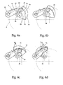
- the cam 14 must be in the corresponding angular position and the squeegee are closed, resp. the distance s is 0. This situation is shown in FIGS. 3a, 4a and 5a.
- each angular position of the cams 14 corresponds to an associated distance s between the doctor blades and glue application rollers.
- This situation is illustrated in FIGS. 3c, 4c and 5c.
- the cams 14 are drive-connected to controlled motors 2.
- the angular positions and rotational speeds of the cams 14 to be achieved are calculated on the basis of the product and production parameters by a control device 17 connected to the motors 2 and the motors 2 are correspondingly regulated via the lines 16.
- the variant cam 14 in FIGS. 3 a to 3 d has outer curves 25 both for the control cam 18 and for the complementary control cam 19.
- the variants of cams 14 according to FIGS. 4a to 4d and FIGS. 5a to 5d each have an outer curve 25 and an inner curve 26.
- Another, not shown, variant cam 14 has 2 inner curves 26. It is likewise conceivable to use the cams 18,19 mounted on a cam drum, wherein the axes of the shafts 4 and the cam drums are aligned perpendicular to each other.
Landscapes
- Coating Apparatus (AREA)
- Folding Of Thin Sheet-Like Materials, Special Discharging Devices, And Others (AREA)
Abstract
Description
- Die Erfindung betrifft ein Leimwerk zum Auftragen eines Klebstoffes auf den Buchblockrücken oder angrenzende Bereiche eines in einer Fördereinrichtung vorbeigeführten Buchblocks zusammengetragener Druckbogen, bestehend aus einer flüssigen Klebstoff enthaltenden Wanne, in die wenigstens eine den Klebstoff aufnehmende und an den Buchblockrücken des Buchblocks übertragende, gleichsinnig mit dem Buchblock angetriebene Leimauftragswalze eintaucht, welcher über dem Leimniveau in der Wanne ein durch den veränderbaren Abstand von der Leimauftragswalze die auf den Buchblockrücken zu übertragende Klebstofffilmdicke bestimmender, zur Verstellung mit einem an einer motorisch antreibbaren Welle angetriebenen Betätigungsorgan verbundener Rakel zugeordnet ist.
- Bei der Herstellung von Broschuren, Katalogen, Taschenbüchern, Büchern und Buchblocks durch Verkleben, werden meistens Leimwerke eingesetzt, die den Klebstoff mittels Leimauftragswalzen auf den Buchblockrücken auftragen. Dazu werden die losen Druckbogen oder Blätter zuerst in einer Zusammentrageinrichtung gesammelt, anschliessend im Rückenbereich durch Fräswerkzeuge bearbeitet oder miteinander vernäht und abschliessend unter Verwendung eines Klebstoffes gegenseitig und mit einem Umschlag oder Fälzelstreifen verbunden. Während Rückenbearbeitung, Klebstoffauftrag und Zusammenführung mit Umschlag oder Fälzelstreifen, werden die Druckbogen, unter Freilassung des Rückens und rückennahen Bereichs, seitlich in einer Fördereinrichtung eingespannt, in Rückenlängsrichtung gefördert und an stationären Bearbeitungsstationen vorbeigeführt. Der Leimauftrag erfolgt mittels angetriebenen Leimauftragswalzen, deren Umfangsgeschwindigkeit in etwa der Fördergeschwindigkeit der Fördereinrichtung entspricht. Die Leimauftragswalzen tauchen in den in einer Wanne bevorrateten Klebstoff und fördern diesen in Richtung der zu beleimenden Oberfläche. Sogenannte Rakel bilden mit den Leimauftragswalzen zusammen einen Förderspalt, der die Dicke des Leimfilms auf den Leimauftragswalzen bestimmt. Soll die Beleimung nicht auf der ganzen Länge des Buchblockrückens erfolgen, werden die Rakel mittels Antriebsvorrichtungen senkrecht zur Oberfläche der Leimauftragswalzen auf und zu bewegt. Nach dem Auftrag am Buchblockrücken wird der Klebstofffilm durch eine Egalisiereinrichtung, beispielsweise eine zur Förderrichtung gegenläufig angetriebene Walze, geebnet. Ein Leimwerk der genannten Art ist in [Industrielle Buchbinderei 2001 von Liebau/Heinze, Kapitel 4.2.3.3.6 Technische Mittel des Klebstoffauftrags] offenbart.
- Nach einem ersten Stand der Technik werden die Leimrakel mittels Steuerkurven, die winkelsynchron mit dem Maschinentakt angetrieben sind, geöffnet und geschlossen. Diese Lösung hat den Nachteil, dass aus geometrischen Gründen, die Steuerkurven nicht mit der erforderlichen Steigung gestaltet werden können, und somit die Veränderung der Leimfilmdicke auf den Auftragswalzen zu flach erfolgt. Die Verstellung der Leimfilmlänge und Dicke muss entweder von Hand vorgenommen werden oder mittels einer komplizierten Mechanik, die durch Stellmotoren angetrieben wird. Dadurch wird die ohnehin hohe Trägheit des Systems zusätzlich erhöht und die maximal erreichbare Produktionsgeschwindigkeit entsprechend begrenzt.
- Ein weiterer Stand der Technik wird durch die
EP 1 208 998 des Anmelders offenbart. Der Antrieb der Leimrakel erfolgt dabei mittels sehr direkt angekoppelten steuerbaren Elektromotoren. Diese Antriebe lassen sich einfach über die Maschinensteuerung bedienen und steuern. Direkte Eingriffe durch den Bediener sind nicht notwendig. Nachteilig ist der wegen der nötigen Auflösung grosse zurückzulegende Weg des Motors und die daraus resultierende Begrenzung der maximal erreichbaren Produktionsgeschwindigkeit. - Nach einem weiteren Stand der Technik wird in der
DE 102 42 259 vorgeschlagen, die Rakel mittels piezokeramischen Aktuatoren anzutreiben. Bedingt durch den relativ kleinen erreichbaren Hub der Piezokeramik, muss eine grosse Wegübersetzung zwischen Antrieb und Rakel gewählt werden, was zu einer hohen mechanischen Belastung des Piezokristalls führt. Die maximal mögliche Schaltgeschwindigkeit wird somit durch die mechanische Festigkeit des Piezokristalls stark limitiert. - Ein weiterer, in der
DE 102 42 260 offenbarte Stand der Technik, schlägt den Einsatz von über Druckluft steuerbare Kontraktionsschläuche als Aktuatoren für den Antrieb der Rakel vor. Es ist bekannt, dass durch die Kompressibilität der Druckluft Verzögerungen zwischen dem Schaltzeitpunkt der Druckluft und der Reaktion des Antriebs erfolgen, deren negative Auswirkungen mit steigender Maschinengeschwindigkeit zunehmen. Somit wird die maximal mögliche Produktionsgeschwindigkeit stark begrenzt. - Die Genauigkeit von Leimauftragsanfang und Ende am Buchblockrücken ist direkt von der Form des Leimfilms auf den Leimauftragswalzen abhängig. Idealerweise müsste der Leimfilm an Anfang und Ende durch senkrecht zur Walze stehende Flächen begrenzt sein. Dies ist aus verschiedenen physikalischen Gründen nicht möglich. Der Leimfilm wird deshalb an dessen Anfang und Ende stets mehr oder weniger steile Rampen aufweisen, wobei die Steilheit der Rampen durch das Verhältnis der Geschwindigkeit des Rakels senkrecht zur Leimauftragswalze und der Umfangsgeschwindigkeit der Leimauftragswalze gegeben ist. Da die Umfangsgeschwindigkeit der Leimauftragswalzen durch die Teilung von Buch zu Buch und die Produktionsgeschwindigkeit gegeben ist, lässt sich die erforderliche Steilheit und Genauigkeit der Rampen ausschliesslich durch entsprechend schnell bewegte Rakel erreichen.
- Es ist somit Aufgabe der Erfindung, an einem Leimwerk mit Leimauftragswalzen, die Geschwindigkeit des Rakelantriebs gegenüber den bekannten Vorrichtungen wesentlich zu erhöhen, unter Beibehaltung einer ausschliesslichen Bedienung über die Steuerung. Zusätzlich sollen das Leimwerk und der Antrieb der Rakel einfach gegenseitig in Eingriff bringbar und trennbar sein.
- Die Aufgabe wird erfindungsgemäss dadurch gelöst, dass das Betätigungsorgan mit einer mit einem Motor antriebsverbundenen Steuerkurve formschlüssig verbunden ist.
- Die Erfindung wird anschliessend unter Bezugnahme auf die Zeichnung, auf die bezüglich aller in der Beschreibung nicht näher erwähnten Einzelheiten verwiesen wird, anhand von Ausführungsbeispielen erläutert. In der Zeichnung zeigen:
- Fig. 1
- eine vereinfachte 3-D-Darstellung eines Leimwerks in Arbeitsposition,
- Fig. 2
- das Leimwerk nach Fig. 1 in entkoppelter Position,
- Fig. 3a - 3d
- eine Detailansicht eines Rakelantriebs in unterschiedlichen Winkelpositionen,
- Fig. 4a - 4d
- eine Detailansicht einer Variante eines Rakelantriebs in unterschiedlichen Winkelpositionen und
- Fig. 5a - 5d
- eine Detailansicht einer weiteren Variante eines Rakelantriebs in unterschiedlichen Winkelpositionen.
- Die Fig. 1 zeigt ein Leimwerk 1 eines Klebebinders zum Beleimen des Rückens 20 von Buchblocks 21. Aus Gründen der Übersichtlichkeit ist der Buchblock 21 durchsichtig dargestellt mittels strichpunktierten Seitenkanten. Das Leimwerk 1 besteht im Wesentlichen aus einer, den Klebstoff 8 enthaltenden Wanne 3, an der Leimauftragswalzen 6 drehbar gelagert sind, die in den Klebstoff 8 eintauchen. Die Leimauftragswalzen 6 werden durch einen nicht dargestellten Antrieb angetrieben und drehen gleichsinnig mit den in Förderrichtung 22 vorbeigeführten Buchblocks 21. Der an der Oberfläche der Leimauftragswalzen 6 haftende Klebstoff 8 wird mittels Rakeln 5 entsprechend dem Abstand s zwischen den Rakeln 5 und Leimauftragswalzen 6 zu einem homogenen Leimfilm geformt, wobei die Dicke des Leimfilms dem Abstand s entspricht. Bereiche am Anfang und Ende des Buchblocks 21 sollen dabei frei von Klebstoff 8 bleiben. Dies wird erreicht durch Zustellung der Rakel 5 gegen die Leimauftragswalzen 6 womit der Abstand s verringert wird. In diesen Bereichen kann kein Kontakt mehr zwischen Leimfilmoberfläche und Buchblockrücken 20 erfolgen und die Übertragung von Klebstoff 8 an den Buchblockrücken 20 wird vermieden. Nach dem Leimauftrag wird mittels einer gegenläufig zur Förderrichtung 22 angetriebenen Walze 7, einem sogenannten Spinner, der Leimfilm am Buchblockrücken 20 geglättet, überschüssiger Klebstoff 8 abgetragen und in die Wanne 3 zurückgeführt. Die Rakel 5 sind an Wellen 4, die schwenkbar in Lagerungen 9 der Wanne 3 gelagert sind, befestigt. Die Verstellung der Rakel 5 erfolgt durch an den Wellen 4 angeordnete Betätigungsorgane 10, die mit Kurvenscheiben 14 formschlüssig antriebsverbunden sind. Die Kurvenscheiben 14 sind mit Motoren 2 antriebsverbunden und am Maschinengestell 15 ortsfest befestigt. Vorteilhafterweise weist das Betätigungsorgan 10 zwei drehbar gelagerte Führungsrollen 11,12 auf, von denen die erste Führungsrolle 11 an der Steuerkurve 18 und die zweite Führungsrolle an einer zur Steuerkurve 18 komplementär wirkenden Steuerkurve 19 anliegen. Je nach Variante der Kurvenscheibe 14 wird das Betätigungsorgan 10 durch einen oder 2 Hebel 13 gebildet. Es kann sinnvoll sein, für die Verarbeitung verschiedener Klebstoffe 8 unterschiedliche Leimwerke 1 einzusetzen. Die Leimwerke 1 lassen sich als komplette Einheiten in der Richtung der Achsen der Leimauftragswalzen 6 in die Maschine ein- und ausfahren. Die Auftrennung des Rakelantriebs erfolgt vorzugsweise zwischen den Führungsrollen 11,12 und den Steuerkurven 18,19. Zu diesem Zweck verfügen die Steuerkurven 18,19 über Einlaufabschnitte 23, die beim Einfahren des Leimwerks 1 einen Kontakt zwischen den Führungsrollen 11,12 und den Steuerkurven vermeiden. Die Kurvenscheibe 14 muss sich dabei in der entsprechenden Winkelposition befinden und die Rakel sind geschlossen, resp. der Abstand s beträgt 0. Diese Situation ist in den Fig. 3a, Fig. 4a und Fig. 5a dargestellt. Anschliessend werden die Kurvenscheiben 14, in den Beispielen im Gegenuhrzeigersinn derart gedreht, dass sich die Anfänge der Arbeitsabschnitte 24 bei den Führungsrollen 11,12 befinden. Die Führungsrollen 11,12 haben somit Kontakt mit den Steuerkurven 18,19, wobei der Abstand s zwischen den Rakeln 5 und den Leimauftragswalzen 6 noch immer 0 beträgt. Diese Situation ist in den Fig. 3b, Fig. 4b und Fig. 5b dargestellt. Diese Winkelposition der Kurvenscheiben 14 entspricht dem Beginn des Arbeitshubes. In den Fig. 3d, Fig. 4d und Fig. 5d sind die Kurvenscheiben 14 in der Endlage dargestellt und der Abstand s hat sein Maximum erreicht. Durch Verdrehen der Kurvenscheiben 14 innerhalb der Arbeitsabschnitte 24 lässt sich somit der Abstand s einstellen, wobei jede Winkelposition der Kurvenscheiben 14 einem zugehörigen Abstand s zwischen den Rakeln und Leimauftragswalzen entspricht. Diese Situation ist in den Fig. 3c, Fig. 4c und Fig. 5c dargestellt. Die Kurvenscheiben 14 sind mit geregelten Motoren 2 antriebsverbunden. Die zu erreichenden Winkelpositionen und Drehgeschwindigkeiten der Kurvenscheiben 14 werden auf der Basis der Produkte- und Produktionsparameter durch eine mit den Motoren 2 verbundene Steuervorrichtung 17 berechnet und die Motoren 2 über die Leitungen 16 entsprechend geregelt.
- Die Gestaltung der Kurvenscheibe 14 mit den wesentlichen Merkmalen nach den Ansprüchen lässt mehrere Gestaltungsvarianten zu.
- Die Variante Kurvenscheibe 14 in den Fig. 3a bis 3d weist sowohl für die Steuerkurve 18, wie auch für die komplementäre Steuerkurve 19 Aussenkurven 25 auf. Die Varianten Kurvenscheiben 14 nach den Fig. 4a bis 4d und Fig. 5a bis 5d verfügen über je eine Aussenkurve 25 und eine Innenkurve 26. Eine weitere, nicht dargestellte Variante Kurvenscheibe 14, verfügt über 2 Innenkurven 26. Es ist ebenfalls denkbar, die Steuerkurven 18,19 an einer Kurventrommel anzubringen, wobei die Achsen der Wellen 4 und der Kurventrommeln senkrecht zueinander ausgerichtet sind.
Claims (9)
- Leimwerk (1) zum Auftragen eines Klebstoffes (8) auf den Buchblockrücken (20) oder angrenzende Bereiche eines in einer Fördereinrichtung vorbeigeführten Buchblocks (21) zusammengetragener Druckbogen, bestehend aus einer flüssigen Klebstoff (8) enthaltenden Wanne (3), in die wenigstens eine den Klebstoff (8) aufnehmende und an den Buchblockrücken (20) des Buchblocks (21) übertragende, gleichsinnig mit dem Buchblock (21) angetriebene Leimauftragswalze (6) eintaucht, welcher über dem Leimniveau in der Wanne (3) ein durch den veränderbaren Abstand (s) von der Leimauftragswalze (6) die auf den Buchblockrücken (20) zu übertragende Klebstofffilmdicke bestimmender, zur Verstellung mit einem an einer motorisch antreibbaren Welle (4) angetriebenen Betätigungsorgan (10) verbundener Rakel (5) zugeordnet ist, dadurch gekennzeichnet, dass das Betätigungsorgan (10) mit einer mit einem Motor (2) antriebsverbundenen Steuerkurve (14) formschlüssig verbunden ist.
- Vorrichtung nach Anspruch 1, dadurch gekennzeichnet, dass das Betätigungsorgan (10) zwei Führungsrollen (11,12) aufweist, die jeweils an der Steuerkurve (18) resp. an einer komplementär wirkenden Steuerkurve (19) anliegen.
- Vorrichtung nach Anspruch 1 oder 2, dadurch gekennzeichnet, dass die Steuerkurven (18,19) jeweils unterschiedlich ausgebildet sind.
- Vorrichtung nach einem der Ansprüche 1 bis 3, dadurch gekennzeichnet, dass die Steuerkurven (18,19) einen Einlauf- (23) und einen in Laufrichtung an letzteren anschliessenden Arbeitsabschnitt (24) aufweisen.
- Vorrichtung nach einem der Ansprüche 2 bis 4, dadurch gekennzeichnet, dass die Führungsrollen (11,12) jeweils an einer Aussenkurve (25) der Steuerkurve (18,19) anliegen.
- Vorrichtung nach einem der Ansprüche 2 bis 4, dadurch gekennzeichnet, dass die Führungsrollen (11,12) jeweils an einer Innenkurve (26) der Steuerkurve (18,19) anliegen.
- Vorrichtung nach einem der Ansprüche 2 bis 4, dadurch gekennzeichnet, dass die Führungsrollen (11,12) jeweils an einer Aussen- (25) und einer Innenkurve (26) anliegen.
- Vorrichtung nach einem der Ansprüche 1 bis 7, dadurch gekennzeichnet, dass das Betätigungsorgan (10) als Hebelwerk ausgebildet ist.
- Vorrichtung nach Anspruch 8, dadurch gekennzeichnet, dass die Führungsrollen (11,12) frei drehbar an dem Hebelwerk gelagert sind.
Priority Applications (4)
| Application Number | Priority Date | Filing Date | Title |
|---|---|---|---|
| AT06405282T ATE516966T1 (de) | 2006-06-30 | 2006-06-30 | Leimwerk für buchblocks mit verstellbarer rakel |
| EP06405282A EP1872964B1 (de) | 2006-06-30 | 2006-06-30 | Leimwerk für Buchblocks mit verstellbarer Rakel |
| JP2007141480A JP5063188B2 (ja) | 2006-06-30 | 2007-05-29 | 移送方向に案内される本の中身の背又はその隣接領域に接着剤を塗布するための糊付け装置 |
| US11/823,718 US7959394B2 (en) | 2006-06-30 | 2007-06-28 | Glue applicator for applying an adhesive to the spine or adjacent areas of a book block being conducted past the glue applicator in a transport direction |
Applications Claiming Priority (1)
| Application Number | Priority Date | Filing Date | Title |
|---|---|---|---|
| EP06405282A EP1872964B1 (de) | 2006-06-30 | 2006-06-30 | Leimwerk für Buchblocks mit verstellbarer Rakel |
Publications (2)
| Publication Number | Publication Date |
|---|---|
| EP1872964A1 true EP1872964A1 (de) | 2008-01-02 |
| EP1872964B1 EP1872964B1 (de) | 2011-07-20 |
Family
ID=37487890
Family Applications (1)
| Application Number | Title | Priority Date | Filing Date |
|---|---|---|---|
| EP06405282A Not-in-force EP1872964B1 (de) | 2006-06-30 | 2006-06-30 | Leimwerk für Buchblocks mit verstellbarer Rakel |
Country Status (4)
| Country | Link |
|---|---|
| US (1) | US7959394B2 (de) |
| EP (1) | EP1872964B1 (de) |
| JP (1) | JP5063188B2 (de) |
| AT (1) | ATE516966T1 (de) |
Cited By (4)
| Publication number | Priority date | Publication date | Assignee | Title |
|---|---|---|---|---|
| DE202008006314U1 (de) | 2008-05-08 | 2008-07-31 | Heidelberger Druckmaschinen Ag | Vorrichtung zum Auftragen von Klebstoff |
| CN103568489A (zh) * | 2013-11-25 | 2014-02-12 | 安徽华印机电股份有限公司 | 上背胶驱动装置 |
| CN103796842A (zh) * | 2011-09-16 | 2014-05-14 | 好利用国际株式会社 | 无线装订制书装置的涂胶单元 |
| CN114312096A (zh) * | 2022-01-06 | 2022-04-12 | 深圳市精密达机械有限公司 | 断胶凸轮组和胶订机 |
Families Citing this family (10)
| Publication number | Priority date | Publication date | Assignee | Title |
|---|---|---|---|---|
| US7963733B2 (en) * | 2008-10-01 | 2011-06-21 | Perfect Systems, Llc | Apparatus for and a method of binding of a perfect bound book |
| US20130170925A1 (en) * | 2011-12-28 | 2013-07-04 | Donnie Donselman | Book Binding Adhesive Application Controller |
| EP2634008B1 (de) * | 2012-02-29 | 2014-07-30 | Müller Martini Holding AG | Verfahren und Vorrichtung zum Auswechseln einer Klebstoff-Auftragswalze |
| ITMI20120747A1 (it) * | 2012-05-04 | 2013-11-05 | Meccanotecnica Spa | Applicatore di colla da legatoria a pressione con livellamento del velo di colla |
| KR101385060B1 (ko) | 2012-09-17 | 2014-04-15 | 김종구 | 제본기의 접착제 도포장치 |
| US8920096B2 (en) | 2012-12-27 | 2014-12-30 | Donnie Donselman | Book binding adhesive application controller |
| CN103434296B (zh) * | 2013-09-05 | 2015-02-11 | 浙江新华数码印务有限公司 | 一种厚型平装书胶订方法 |
| US9789645B2 (en) | 2016-01-26 | 2017-10-17 | Elum Inc. | Glue delivery system |
| JP6760740B2 (ja) * | 2016-02-26 | 2020-09-23 | 東芝テック株式会社 | レシートサーバー及びプログラム |
| CN113427926B (zh) * | 2021-06-01 | 2023-07-07 | 河南省中凌煜新材料科技有限公司 | 一种含有聚醋酸乙烯酯乳液胶液粘贴书籍外壳装置 |
Citations (8)
| Publication number | Priority date | Publication date | Assignee | Title |
|---|---|---|---|---|
| DE1002729B (de) * | 1954-09-16 | 1957-02-21 | Hans Mueller | Maschine zum Verleimen und Broschieren von Buechern |
| DE2635108A1 (de) * | 1975-08-04 | 1977-02-24 | Comstock & Wescott | Vorrichtung zur aufbringung von klebstoff auf die parallelen raender von blaettern |
| DE3026446A1 (de) | 1979-08-13 | 1981-03-26 | VEB Kombinat Polygraph "Werner Lamberz" Leipzig, 04318 Leipzig | Vorrichtung zum auftragen von schmelzklebstoff auf blockruecken |
| EP0769368A2 (de) * | 1995-10-13 | 1997-04-23 | Marquip, Inc. | Vorrichtung und Verfahren zum Auftragen einer viskosen Flüssigkeit auf eine Oberfläche |
| EP1084864A1 (de) * | 1999-09-17 | 2001-03-21 | Grapha-Holding Ag | Leimwerk zum Auftragen eines Klebstoffes auf den Rücken oder angrenzende Bereiche eines vorbeigefürten Buchblockes. |
| EP1208998A1 (de) | 2000-11-17 | 2002-05-29 | Grapha-Holding AG | Leimwerk zum Auftragen eines Klebstoffes |
| DE10242260A1 (de) | 2002-09-12 | 2004-03-25 | Kolbus Gmbh & Co. Kg | Vorrichtung zum Auftragen eines Klebstoffs auf den Rücken oder rückennahen Bereichen der Seitenflächen eines Buchblocks |
| DE10242259A1 (de) | 2002-09-12 | 2004-03-25 | Kolbus Gmbh & Co. Kg | Vorrichtung zum Auftragen eines Klebstoffs auf den Rücken oder rückennahen Seitenbereichen der Seitenflächen eines Buchblocks |
Family Cites Families (6)
| Publication number | Priority date | Publication date | Assignee | Title |
|---|---|---|---|---|
| JPS591824Y2 (ja) * | 1979-04-28 | 1984-01-19 | 小森印刷機械株式会社 | 製本機の糊付け装置における糊付け長さ調節装置 |
| JPS63113530U (de) * | 1987-01-13 | 1988-07-21 | ||
| JPH0658384A (ja) * | 1992-08-06 | 1994-03-01 | Elna Co Ltd | カム装置 |
| EP0628429B1 (de) * | 1993-06-11 | 1997-04-23 | Ferag AG | Verfahren und Vorrichtung zum Verbinden der Bogen eines mehrblättrigen Druckereiproduktes |
| JP4311823B2 (ja) * | 1999-09-01 | 2009-08-12 | ホリゾン・インターナショナル株式会社 | 製本用背糊付け装置 |
| JP2004100735A (ja) * | 2002-09-05 | 2004-04-02 | Japan Aviation Electronics Industry Ltd | 共役カムにおけるカムフォロアとカム面の隙間の調整機構 |
-
2006
- 2006-06-30 AT AT06405282T patent/ATE516966T1/de active
- 2006-06-30 EP EP06405282A patent/EP1872964B1/de not_active Not-in-force
-
2007
- 2007-05-29 JP JP2007141480A patent/JP5063188B2/ja not_active Expired - Fee Related
- 2007-06-28 US US11/823,718 patent/US7959394B2/en not_active Expired - Fee Related
Patent Citations (8)
| Publication number | Priority date | Publication date | Assignee | Title |
|---|---|---|---|---|
| DE1002729B (de) * | 1954-09-16 | 1957-02-21 | Hans Mueller | Maschine zum Verleimen und Broschieren von Buechern |
| DE2635108A1 (de) * | 1975-08-04 | 1977-02-24 | Comstock & Wescott | Vorrichtung zur aufbringung von klebstoff auf die parallelen raender von blaettern |
| DE3026446A1 (de) | 1979-08-13 | 1981-03-26 | VEB Kombinat Polygraph "Werner Lamberz" Leipzig, 04318 Leipzig | Vorrichtung zum auftragen von schmelzklebstoff auf blockruecken |
| EP0769368A2 (de) * | 1995-10-13 | 1997-04-23 | Marquip, Inc. | Vorrichtung und Verfahren zum Auftragen einer viskosen Flüssigkeit auf eine Oberfläche |
| EP1084864A1 (de) * | 1999-09-17 | 2001-03-21 | Grapha-Holding Ag | Leimwerk zum Auftragen eines Klebstoffes auf den Rücken oder angrenzende Bereiche eines vorbeigefürten Buchblockes. |
| EP1208998A1 (de) | 2000-11-17 | 2002-05-29 | Grapha-Holding AG | Leimwerk zum Auftragen eines Klebstoffes |
| DE10242260A1 (de) | 2002-09-12 | 2004-03-25 | Kolbus Gmbh & Co. Kg | Vorrichtung zum Auftragen eines Klebstoffs auf den Rücken oder rückennahen Bereichen der Seitenflächen eines Buchblocks |
| DE10242259A1 (de) | 2002-09-12 | 2004-03-25 | Kolbus Gmbh & Co. Kg | Vorrichtung zum Auftragen eines Klebstoffs auf den Rücken oder rückennahen Seitenbereichen der Seitenflächen eines Buchblocks |
Cited By (5)
| Publication number | Priority date | Publication date | Assignee | Title |
|---|---|---|---|---|
| DE202008006314U1 (de) | 2008-05-08 | 2008-07-31 | Heidelberger Druckmaschinen Ag | Vorrichtung zum Auftragen von Klebstoff |
| CN103796842A (zh) * | 2011-09-16 | 2014-05-14 | 好利用国际株式会社 | 无线装订制书装置的涂胶单元 |
| CN103796842B (zh) * | 2011-09-16 | 2015-11-25 | 好利用国际株式会社 | 无线装订制书装置的涂胶单元 |
| CN103568489A (zh) * | 2013-11-25 | 2014-02-12 | 安徽华印机电股份有限公司 | 上背胶驱动装置 |
| CN114312096A (zh) * | 2022-01-06 | 2022-04-12 | 深圳市精密达机械有限公司 | 断胶凸轮组和胶订机 |
Also Published As
| Publication number | Publication date |
|---|---|
| US20080003080A1 (en) | 2008-01-03 |
| EP1872964B1 (de) | 2011-07-20 |
| US7959394B2 (en) | 2011-06-14 |
| JP5063188B2 (ja) | 2012-10-31 |
| JP2008012913A (ja) | 2008-01-24 |
| ATE516966T1 (de) | 2011-08-15 |
Similar Documents
| Publication | Publication Date | Title |
|---|---|---|
| EP1872964B1 (de) | Leimwerk für Buchblocks mit verstellbarer Rakel | |
| EP1208998B1 (de) | Leimwerk zum Auftragen eines Klebstoffes | |
| DE102006012084B4 (de) | Vorrichtung und Verfahren zum Anpressen eines Umschlages an einen bewegten Bedruckstoffblock | |
| EP1780038B2 (de) | Einrichtung für das Anreiben einer Buchdecke an den beleimten Aussenflächen von Buchblocks mit separatem Antrieb | |
| DE102009031949A1 (de) | Vorrichtung zum Auftragen von Klebstoff auf einen Buchblock | |
| EP0981487B1 (de) | Verfahren und vorrichtung zum erfassen eines teiles einer äusseren lage einer materialbahn von einer vorratsrolle | |
| EP2738011B1 (de) | Klebebinder mit Kettenantrieb pro Klammer | |
| DE102007019963A1 (de) | Schneidvorrichtung | |
| CH644535A5 (de) | Selektiv konvertierbare vorrichtung zur beschichtung einer sich bewegenden materialbahn. | |
| EP1153872B1 (de) | Vorrichtung und Verfahren zur Vorbereitung eines Buchrückens zum Binden | |
| EP1780037B2 (de) | Einrichtung für das Beleimen der Aussenflächen von Buchblocks | |
| EP1683649A2 (de) | Einstellbare Rakel zum Auftragen von Klebstoff auf Buchblocks | |
| WO2008043748A1 (de) | Schwenkbare anlegewalze im wendewickler | |
| EP2468665B1 (de) | Vorrichtung zum Anlegen eines Umschlags | |
| DE2850740A1 (de) | Vorrichtung zum einschlagen von ueberzugsmaterial um pappen o.ae. flaechenfoermige werkstuecke, insbesondere zur herstellung von bucheinbanddecken | |
| EP2020305B2 (de) | Vorrichtung und Verfahren zum Anpressen eines Umschlages oder Fälzels an einen beleimten Rücken | |
| DE10242259B4 (de) | Vorrichtung zum Auftragen eines Klebstoffs auf den Rücken oder rückennahen Bereich der Seitenflächen eines Buchblocks | |
| DE102005051477A1 (de) | Verfahren und Vorrichtung zum Beziehen eines flach liegenden Zuschnittes mit einem Bezug | |
| CH696436A5 (de) | Vorrichtung zum Anlegen und Anpressen eines Umschlags an einen kontinuierlich in Förderrichtung transportierten Buchblock. | |
| DE1786641C2 (de) | Leimauftragsmaschine für die Herstellung von Wellpappe o.dgl | |
| EP1612306A1 (de) | Vliesleger | |
| DD236700A1 (de) | Leimwerk zur herstellung von buchblocks und mehrlagenbroschuren mit begrenztem leimauftrag | |
| EP0023985A1 (de) | Heftvorrichtung für Druckmaschinen | |
| EP2711192B1 (de) | Vorrichtung zum Anlegen eines Umschlags | |
| DE202008006314U1 (de) | Vorrichtung zum Auftragen von Klebstoff |
Legal Events
| Date | Code | Title | Description |
|---|---|---|---|
| PUAI | Public reference made under article 153(3) epc to a published international application that has entered the european phase |
Free format text: ORIGINAL CODE: 0009012 |
|
| AK | Designated contracting states |
Kind code of ref document: A1 Designated state(s): AT BE BG CH CY CZ DE DK EE ES FI FR GB GR HU IE IS IT LI LT LU LV MC NL PL PT RO SE SI SK TR |
|
| AX | Request for extension of the european patent |
Extension state: AL BA HR MK YU |
|
| 17P | Request for examination filed |
Effective date: 20080303 |
|
| 17Q | First examination report despatched |
Effective date: 20080516 |
|
| AKX | Designation fees paid |
Designated state(s): AT BE BG CH CY CZ DE DK EE ES FI FR GB GR HU IE IS IT LI LT LU LV MC NL PL PT RO SE SI SK TR |
|
| GRAP | Despatch of communication of intention to grant a patent |
Free format text: ORIGINAL CODE: EPIDOSNIGR1 |
|
| GRAS | Grant fee paid |
Free format text: ORIGINAL CODE: EPIDOSNIGR3 |
|
| GRAA | (expected) grant |
Free format text: ORIGINAL CODE: 0009210 |
|
| AK | Designated contracting states |
Kind code of ref document: B1 Designated state(s): AT BE BG CH CY CZ DE DK EE ES FI FR GB GR HU IE IS IT LI LT LU LV MC NL PL PT RO SE SI SK TR |
|
| REG | Reference to a national code |
Ref country code: GB Ref legal event code: FG4D Free format text: NOT ENGLISH |
|
| REG | Reference to a national code |
Ref country code: CH Ref legal event code: EP |
|
| REG | Reference to a national code |
Ref country code: DE Ref legal event code: R096 Ref document number: 502006009849 Country of ref document: DE Effective date: 20110915 |
|
| REG | Reference to a national code |
Ref country code: NL Ref legal event code: VDEP Effective date: 20110720 |
|
| PG25 | Lapsed in a contracting state [announced via postgrant information from national office to epo] |
Ref country code: SE Free format text: LAPSE BECAUSE OF FAILURE TO SUBMIT A TRANSLATION OF THE DESCRIPTION OR TO PAY THE FEE WITHIN THE PRESCRIBED TIME-LIMIT Effective date: 20110720 Ref country code: NL Free format text: LAPSE BECAUSE OF FAILURE TO SUBMIT A TRANSLATION OF THE DESCRIPTION OR TO PAY THE FEE WITHIN THE PRESCRIBED TIME-LIMIT Effective date: 20110720 Ref country code: LT Free format text: LAPSE BECAUSE OF FAILURE TO SUBMIT A TRANSLATION OF THE DESCRIPTION OR TO PAY THE FEE WITHIN THE PRESCRIBED TIME-LIMIT Effective date: 20110720 Ref country code: IS Free format text: LAPSE BECAUSE OF FAILURE TO SUBMIT A TRANSLATION OF THE DESCRIPTION OR TO PAY THE FEE WITHIN THE PRESCRIBED TIME-LIMIT Effective date: 20111120 Ref country code: PT Free format text: LAPSE BECAUSE OF FAILURE TO SUBMIT A TRANSLATION OF THE DESCRIPTION OR TO PAY THE FEE WITHIN THE PRESCRIBED TIME-LIMIT Effective date: 20111121 Ref country code: FI Free format text: LAPSE BECAUSE OF FAILURE TO SUBMIT A TRANSLATION OF THE DESCRIPTION OR TO PAY THE FEE WITHIN THE PRESCRIBED TIME-LIMIT Effective date: 20110720 |
|
| REG | Reference to a national code |
Ref country code: IE Ref legal event code: FD4D |
|
| PG25 | Lapsed in a contracting state [announced via postgrant information from national office to epo] |
Ref country code: SI Free format text: LAPSE BECAUSE OF FAILURE TO SUBMIT A TRANSLATION OF THE DESCRIPTION OR TO PAY THE FEE WITHIN THE PRESCRIBED TIME-LIMIT Effective date: 20110720 Ref country code: LV Free format text: LAPSE BECAUSE OF FAILURE TO SUBMIT A TRANSLATION OF THE DESCRIPTION OR TO PAY THE FEE WITHIN THE PRESCRIBED TIME-LIMIT Effective date: 20110720 Ref country code: GR Free format text: LAPSE BECAUSE OF FAILURE TO SUBMIT A TRANSLATION OF THE DESCRIPTION OR TO PAY THE FEE WITHIN THE PRESCRIBED TIME-LIMIT Effective date: 20111021 Ref country code: CY Free format text: LAPSE BECAUSE OF FAILURE TO SUBMIT A TRANSLATION OF THE DESCRIPTION OR TO PAY THE FEE WITHIN THE PRESCRIBED TIME-LIMIT Effective date: 20110720 Ref country code: PL Free format text: LAPSE BECAUSE OF FAILURE TO SUBMIT A TRANSLATION OF THE DESCRIPTION OR TO PAY THE FEE WITHIN THE PRESCRIBED TIME-LIMIT Effective date: 20110720 |
|
| PG25 | Lapsed in a contracting state [announced via postgrant information from national office to epo] |
Ref country code: CZ Free format text: LAPSE BECAUSE OF FAILURE TO SUBMIT A TRANSLATION OF THE DESCRIPTION OR TO PAY THE FEE WITHIN THE PRESCRIBED TIME-LIMIT Effective date: 20110720 Ref country code: SK Free format text: LAPSE BECAUSE OF FAILURE TO SUBMIT A TRANSLATION OF THE DESCRIPTION OR TO PAY THE FEE WITHIN THE PRESCRIBED TIME-LIMIT Effective date: 20110720 Ref country code: IE Free format text: LAPSE BECAUSE OF FAILURE TO SUBMIT A TRANSLATION OF THE DESCRIPTION OR TO PAY THE FEE WITHIN THE PRESCRIBED TIME-LIMIT Effective date: 20110720 |
|
| PLBE | No opposition filed within time limit |
Free format text: ORIGINAL CODE: 0009261 |
|
| STAA | Information on the status of an ep patent application or granted ep patent |
Free format text: STATUS: NO OPPOSITION FILED WITHIN TIME LIMIT |
|
| PG25 | Lapsed in a contracting state [announced via postgrant information from national office to epo] |
Ref country code: EE Free format text: LAPSE BECAUSE OF FAILURE TO SUBMIT A TRANSLATION OF THE DESCRIPTION OR TO PAY THE FEE WITHIN THE PRESCRIBED TIME-LIMIT Effective date: 20110720 Ref country code: RO Free format text: LAPSE BECAUSE OF FAILURE TO SUBMIT A TRANSLATION OF THE DESCRIPTION OR TO PAY THE FEE WITHIN THE PRESCRIBED TIME-LIMIT Effective date: 20110720 |
|
| 26N | No opposition filed |
Effective date: 20120423 |
|
| PG25 | Lapsed in a contracting state [announced via postgrant information from national office to epo] |
Ref country code: DK Free format text: LAPSE BECAUSE OF FAILURE TO SUBMIT A TRANSLATION OF THE DESCRIPTION OR TO PAY THE FEE WITHIN THE PRESCRIBED TIME-LIMIT Effective date: 20110720 |
|
| REG | Reference to a national code |
Ref country code: DE Ref legal event code: R097 Ref document number: 502006009849 Country of ref document: DE Effective date: 20120423 |
|
| BERE | Be: lapsed |
Owner name: MULLER MARTINI HOLDING A.G. Effective date: 20120630 |
|
| PG25 | Lapsed in a contracting state [announced via postgrant information from national office to epo] |
Ref country code: MC Free format text: LAPSE BECAUSE OF NON-PAYMENT OF DUE FEES Effective date: 20120630 |
|
| REG | Reference to a national code |
Ref country code: FR Ref legal event code: ST Effective date: 20130228 |
|
| PG25 | Lapsed in a contracting state [announced via postgrant information from national office to epo] |
Ref country code: ES Free format text: LAPSE BECAUSE OF FAILURE TO SUBMIT A TRANSLATION OF THE DESCRIPTION OR TO PAY THE FEE WITHIN THE PRESCRIBED TIME-LIMIT Effective date: 20111031 Ref country code: BE Free format text: LAPSE BECAUSE OF NON-PAYMENT OF DUE FEES Effective date: 20120630 Ref country code: FR Free format text: LAPSE BECAUSE OF NON-PAYMENT OF DUE FEES Effective date: 20120702 |
|
| PG25 | Lapsed in a contracting state [announced via postgrant information from national office to epo] |
Ref country code: BG Free format text: LAPSE BECAUSE OF FAILURE TO SUBMIT A TRANSLATION OF THE DESCRIPTION OR TO PAY THE FEE WITHIN THE PRESCRIBED TIME-LIMIT Effective date: 20111020 |
|
| REG | Reference to a national code |
Ref country code: AT Ref legal event code: MM01 Ref document number: 516966 Country of ref document: AT Kind code of ref document: T Effective date: 20120630 |
|
| PG25 | Lapsed in a contracting state [announced via postgrant information from national office to epo] |
Ref country code: AT Free format text: LAPSE BECAUSE OF NON-PAYMENT OF DUE FEES Effective date: 20120630 |
|
| PG25 | Lapsed in a contracting state [announced via postgrant information from national office to epo] |
Ref country code: TR Free format text: LAPSE BECAUSE OF FAILURE TO SUBMIT A TRANSLATION OF THE DESCRIPTION OR TO PAY THE FEE WITHIN THE PRESCRIBED TIME-LIMIT Effective date: 20110720 |
|
| PG25 | Lapsed in a contracting state [announced via postgrant information from national office to epo] |
Ref country code: LU Free format text: LAPSE BECAUSE OF NON-PAYMENT OF DUE FEES Effective date: 20120630 |
|
| PG25 | Lapsed in a contracting state [announced via postgrant information from national office to epo] |
Ref country code: HU Free format text: LAPSE BECAUSE OF FAILURE TO SUBMIT A TRANSLATION OF THE DESCRIPTION OR TO PAY THE FEE WITHIN THE PRESCRIBED TIME-LIMIT Effective date: 20060630 |
|
| PGFP | Annual fee paid to national office [announced via postgrant information from national office to epo] |
Ref country code: DE Payment date: 20150617 Year of fee payment: 10 Ref country code: GB Payment date: 20150622 Year of fee payment: 10 |
|
| PGFP | Annual fee paid to national office [announced via postgrant information from national office to epo] |
Ref country code: CH Payment date: 20150921 Year of fee payment: 10 |
|
| PGFP | Annual fee paid to national office [announced via postgrant information from national office to epo] |
Ref country code: IT Payment date: 20150630 Year of fee payment: 10 |
|
| REG | Reference to a national code |
Ref country code: DE Ref legal event code: R119 Ref document number: 502006009849 Country of ref document: DE |
|
| REG | Reference to a national code |
Ref country code: CH Ref legal event code: PL |
|
| GBPC | Gb: european patent ceased through non-payment of renewal fee |
Effective date: 20160630 |
|
| PG25 | Lapsed in a contracting state [announced via postgrant information from national office to epo] |
Ref country code: DE Free format text: LAPSE BECAUSE OF NON-PAYMENT OF DUE FEES Effective date: 20170103 Ref country code: CH Free format text: LAPSE BECAUSE OF NON-PAYMENT OF DUE FEES Effective date: 20160630 Ref country code: LI Free format text: LAPSE BECAUSE OF NON-PAYMENT OF DUE FEES Effective date: 20160630 |
|
| PG25 | Lapsed in a contracting state [announced via postgrant information from national office to epo] |
Ref country code: GB Free format text: LAPSE BECAUSE OF NON-PAYMENT OF DUE FEES Effective date: 20160630 |
|
| PG25 | Lapsed in a contracting state [announced via postgrant information from national office to epo] |
Ref country code: IT Free format text: LAPSE BECAUSE OF NON-PAYMENT OF DUE FEES Effective date: 20160630 |